P6421-BU120中文资料
P4221-FQ120中文资料

60PPR 96PPR 150PPR 180PPR 200PPR 240PPR 250PPR 256PPR 270PPR 300PPR 360PPR 480PPR 500PPR 512PPR
120PPR 192PPR 300PPR 360PPR 400PPR 480PPR 500PPR 512PPR 540PPR 600PPR 720PPR 960PPR 1000PPR 1024PPR
240PPR 384PPR 600PPR 720PPR 800PPR 960PPR 1000PPR 1024PPR 1080PPR 1200PPR 1440PPR 1920PPR 2000PPR 2048PPR
7
Programming of Switches: \CCW=set to left; | Cntr=set center; /CW=set to right Note: for SW5 (right hand column PPR x 4) Time Settings: CW=other columns; Cntr=5-10µsec; CCW=25-35µsec
H e r c u l e s
6000 Series
4000 Series
For the latest specifications visit our website
元器件交易网
Hercules Encoders “Value Added” Programmable Encoder
6
Series 4000 and 6000 Programmable Encoders
Standard Features • 4000 Series - Space-Saving Enclosure, 1-1/2"D x 3"H x 3"W, 25 to 4096 PPR. • 6000 Series - Internal Space for 3 Separate Encoders, 25 to 4096 PPR. • Built-In Anti-Jitter Circuitry. • Operating Voltage Flexibility - 8 to 28Vdc, 5Vdc with TTL Outputs and Line Drivers, etc. • Low Supply Current Requirements - Only 50 Milliamperes per Encoder • Extra Heavy Duty 1/2"D Shafts - Optional
PST 642U变压器保护测控装置技术说明书
PST 642U 变压器保护测控装置产品说明书版本修改记录表
10 9 8 7 6 5 4 3 2 1 序号 V1.22 V1.10 V1.00 说明书版本号 增加方向元件 改进版本 初始版本 修改摘要 PST 642UV1.22 PST 642UV1.10 PST 642UV1.00 软件版本号 2011.3 2009.04 2007.04 修改日期
序号 1 2 3 4 5 6 7 8 9 模件名称 交流模件 CPU 模件 面板模件 DIO 模件 TRIP 模件 电源模件 母板模件 通信模件 时钟同步模件 初始版本(2006-02) PST 640U-AC.A-A EDP 03-CPU.A-A EDP 03-PNL.A-A PSL 640U-DIO.A-A PSL 640U-TRIP.A-A EDP 03-PWR.A-A EDP 03-MB.A-A EDP 03-COM.B-A EDP 03-CLK.A-A E03-MB.A-B PSL 640U-TRIP.A-B EDP 03-CPU.B-A 第一次修改版本(2008-08) 第二次修改版本
*
技术支持
电话: (025)51183073 传真: (025)51183077
* * *
本说明书可能会被修改,请注意核对实际产品与说明书的版本是否相符 2007 年 4 月 第 2 版 第 1 次印刷 国电南自技术部监制
目
版本声明
录
1 概述 ............................................................................................................................................ 1 1.1 保护功能配置.........
6MBI225U-120中文资料
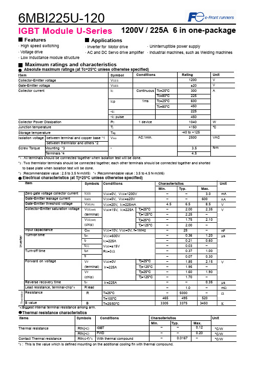
6MBI225U-1201200V / 225A 6 in one-packageFeatures· High speed switching· Voltage drive· Low inductance module structureApplications · Inverter for Motor drive· AC and DC Servo drive amplifierMaximum ratings and characteristicsThermal resistance characteristicsThermal resistanceContact Thermal resistance––0.12––0.20–0.0167 –IGBTFWDWith thermal compound°C/W°C/W°C/W*2 : Two thermistor terminals should be connected together, each other terminals should be connected together and shortedto base plate when isolation test will be done.*3 :Recommendable value : 2.5 to 3.5 N·m(M5) *4 :Recommendable value : 3.5 to 4.5 N·m(M6)Rth(j-c)Rth(j-c)Rth(c-f)*5IGBT Module U-Series*5 : This is the value which is defined mounting on the additional cooling fin with thermal compound.4Items Symbols Conditions Characteristics UnitMin.Typ. Max.· Uninterruptible power supply· Industrial machines, such as Welding machinesCharacteristics (Representative)VGE=0V, f= 1MHz, Tj= 25°CVcc=600V, I=225A, Tj= 25°CCollector current vs. Collector-Emitter voltage (typ.)Tj= 125°C / chipCapacitance vs. Collector-Emitter voltage (typ.)Dynamic Gate charge (typ.)Collector current vs. Collector-Emitter voltage (typ.)Tj= 25°C / chipCollector current vs. Collector-Emitter voltage (typ.)VGE=15V / chipTj=25°C / chipCollector-Emitter voltage vs. Gate-Emitter voltage (typ.)010020030040050060012345C o l l e c t o r c u r r e n t : I c [A ]VGE=20V15V12V10V8V010020030040050060012345C o l l e c t o r c u r r e n t : I c [A ]VGE=20V 15V12V10V8V010020030040050060001234C o l l e c t o r c u r r e n t : I c [A ]Tj=125°CTj=25°C246810510152025C o l l e c t o r - E m i t t e r v o l t a g e : V C E [ V ]Ic=450A Ic=225A Ic= 112.5A0.11.010.0100.0102030C a p a c i t a n c e : C i e s , C o e s , C r e s [ n F ]200400600800100012001400C o l l e c t o r -E m i t t e r v o l t a g e : V C E [ 200V /d i v ]G a t e - E m i t t e r v o l t a g e : V G E [ 5V /d i v]Vcc=600V, Ic=225A, VGE=±15V, Tj= 25°CStray inductance <= 100nHSwitching loss vs. Collector current (typ.)Vcc=600V, VGE=±15V, Rg=3ΩVcc=600V, Ic=225A, VGE=±15V, Tj= 125°C+VGE=15V,-VGE <= 15V, RG >= 3Ω ,Tj <= 125°CSwitching time vs. Collector current (typ.)Vcc=600V, VGE=±15V, Rg=3Ω, Tj=125°CSwitching time vs. Gate resistance (typ.)Switching time vs. Collector current (typ.)Vcc=600V, VGE=±15V, Rg=3Ω, Tj= 25°CReverse bias safe operating area (max.)Switching loss vs. Gate resistance (typ.)10100100010000100200300400S w i t c h i n g t i m e : t o n , t r , t o f f , t f [ n s e c ]Collector current : Ic [ A ]10100100010000100200300400S w i t c h i n g t i m e : t o n , t r , t o f f , t f [ n s e c ]Collector current : Ic [ A ]10100100010000110100S w i t c h i n g t i m e : t o n , t r , t o f f , t f [ n s e c ]Gate resistance : Rg [ Ω ]trtftoffton 01020304050100200300400500S w i t c h i n g l o s s : E o n , E o f f , E r r [ m J /p u l s e ]Collector current : Ic [ A ]Eon(125°C)Eon(25°C)Eoff(125°C)Err(125°C)Err(25°C)Eoff(25°C)0255075100125150110100S w i t c h i n g l o s s : E o n , E o f f , E r r [ m J /p u l s e ]Gate resistance : Rg [ Ω ]EoffErrEon0100200300400500600200400600800100012001400C o l l e c t o r c u r r e n t : I c [ A ]Collector - Emitter voltage : VCE [ V ]Transient thermal resistance (max.)Reverse recovery characteristics (typ.)Vcc=600V, VGE=±15V, Rg=3ΩForward current vs. Forward on voltage (typ.)chipTemperature characteristic (typ.)01002003004005006001234F o r w a r d c u r r e n t : I F [ A ]Forward on voltage : VF [ V ]Tj=125°CTj=25°C101001000100200300400500R e v e r s e r e c o v e r y c u r r e n t : I r r [ A ]R e v e r s e r e c o v e r y t i m e : t r r [ n s e c ]Forward current : IF [ A ]Irr (125°C)Irr (25°C)trr (125°C)trr (25°C)0.0010.0100.1001.0000.0010.0100.1001.000T h e r m a l r e s i s t a n s e : R t h (j -c ) [ °C /W ]Pulse width : Pw [ sec ]0.1110100-60-40-20020406080100120140160180Temperature [°C ]R e s i s t a n c e : R [ k Ω ]Outline Drawings, mmM6296MBI225U-120IGBT ModuleEquivalent Circuit Schematic[Thermister]135111210987246[Inverter]。
ADI ADuM6420A带DC/DC转换器的四道数字隔离器解决方案

ADI ADuM6420A带DC/DC转换器的四道数字隔离器解决方案ADI公司的ADuM6420A/ADuM6421A/ADuM6422A是采用isoPower®集成隔离式直流/直流转换器的四通道数字隔离器.基于ADI 公司的iCoupler®技术,可提供稳压隔离式电源,在配备铁氧体的2 层印刷电路板(PCB)上在满载时符合CISPR 32/EN 55032 B 级限制.100mA输出电流,满足AEC-Q100汽车应用规范, 在500 mW的隔离式设计中不再需要单独的隔离式直流/直流转换器.具有四路DC到100Mbps信号隔离通路,可提供外形小巧四个独立的完全隔离式解决方案.高温125C工作温度,共模瞬态免疫为100 kV/μs, VIORM = 566 V peak.主要用在RS-232 收发器,电源启动偏置和栅极驱动,隔离式传感器接口和工业可编程逻辑控制器(PLC)以及汽车车载充电器(OBC)和DC/DC转换器.本文介绍了ADuM6420A/ADuM6421A/ADuM6422A/ADuM6423A/ ADuM6424A主要特性,功能框图,.评估板EVAL-ADUM6421ARNZ/ EVAL-ADUM6421AURNZ主要特性,电路图,材料清单和PCB设计图.The ADuM6420A/ADuM6421A/ADuM6422A/ADuM6423A/ ADuM6424A1 are quad-channel digital isolators with an isoPower®, integrated, isolated dc-to-dc converter. Based on the Analog Devices, Inc., iCoupler® technology, the dc-to-dc converter provides regulated, isolated power that meets CISPR 32/EN 55032 Class B limits at a full load on a 2-layer printed circuit board (PCB) with ferrites. Popular voltage combinations and the associated output current levels are listed in Table 1.The ADuM6420A/ADuM6421A/ADuM6422A/ADuM6423A/ ADuM6424A eliminate the need for a separate, isolated dc-to-dc converter in 500 mW, isolated designs. The iCoupler chip scale transformer technology is used for isolated logic signals and for the magnetic components of the dc-to-dc converter. The result is a small form factor, total isolation solution.The ADuM6420A/ADuM6421A/ADuM6422A/ADuM6423A/ ADuM6424A isolators provide four independent isolation channels (see the Pin Configurations and Function Descriptions for additional information).ADuM6420A主要特性:isoPower integrated, isolated dc-to-dc converter100 mA output supplyAEC-Q100 qualified for automotive applicationsADuM6421AW (ADuM6423AW pending)Meets CISPR 32/EN55032 Class B emission limits up to 5 Mbps at a full load on a 2-layer PCBQuad dc to 100 Mbps signal isolation channels28-lead, fine pitch, SOIC with 8.3 mm minimum creepageHigh temperature operation: 125C maximumHigh common-mode transient immunity: 100 kV/μsSafety and regulatory approvals (pending)UL recognition (pending)5000 V rms for 1 minute per UL 1577CSA Component Acceptance Notice 5A (pending)VDE V 0884-11 certificate of conformity (pending)VIORM = 566 V peakCQC certification per GB4943.1-2011 (pending)ADuM6420A应用:RS-232 transceiversPower supply start-up bias and gate drivesIsolated sensor interfacesAutomotive on-board charger (OBC) and dc to dcIndustrial programmable logic controllers (PLCs)图1.ADuM6420A功能框图评估板EVAL-ADUM6421ARNZThe ADuM6420A/ADuM6421A/ADuM6422A/ADuM6423A/ ADuM6424A devices integrate fouriCoupler® on-off keying (OOK) digital isolation channels and iCoupler chip scale isoPower® transformer technology.This iCoupler transformer technology enables a small form factor integrated, reinforced isolated signal and power solution, in applications requiring up to 500 mW of isolated power.Available dc-to-dc converter supply configurations and maximum available power at the elevated ambient temperatures are specified in the ADuM6420A/ADuM6421A/ADuM6422A/ADuM6423A/ ADuM6424A data sheet.The ADuM6420A/ADuM6421A/ADuM6422A/ADuM6423A/ ADuM6424A devices provide regulated, isolated power that meets CISPR 32/EN 55032, Class B limits at full load on a 2-layer printed circuit board (PCB) with ferrite beads. Radiated emissions test plots of theEVAL-ADUM6421ARNZ/EVAL-ADUM6421AURNZ are provided in Figure 4 and Figure 5. All devices inthe family include the same isolated dc-to-dc converter and are differentiated by directional digital channel configurations.The EVAL-ADUM6421ARNZ includes the ADuM6421ABRNZ5 quad-channel digital isolator with integrated, isolated dc-to-dc converter. Alternatively, the EVAL-ADUM6421AURNZ leaves the isolator position unpopulated to support evaluation of the ADuM6420A, ADuM6421A, ADuM6422A, ADuM6423A, or ADuM6424A.Full specifications for the ADuM6420A/ADuM6421A/ ADuM6422A/ADuM6423A/ADuM6424A are available in the ADuM6420A/ADuM6421A/ADuM6422A/ADuM6423A/ ADuM6424A data sheet, which must be consulted in conjunction with this user guide when using the evaluation boards.评估板EVAL-ADUM6421ARNZ主要特性:isoPower integrated, isolated dc-to-dc converterMeets CISPR 32/EN 55032, Class B emission limitsOn-board 6 V to 9 V LDO power supply that provides 5 V to the VDDP pin5 V input operation and selectable 3.3 V or 5 V isolated dc-to-dc converter outputScrew terminal connectors for the followingLDO power supply5 V direct power supplyOff board PDIS controlIsolated output supplyEVALUATION KIT CONTENTSEVAL-ADUM6421ARNZ, includes the ADuM6421ABRNZ5EVAL-ADUM6421AURNZ, requires the ADuM6420A, ADuM6421A, ADuM6422A, ADuM6423A, or ADuM6424A to be ordered separately图2.评估板EVAL-ADUM6421ARNZ外形图图3.评估板EVAL-ADUM6421AURNZ外形图图4.评估板EVAL-ADUM6421ARNZ/EVAL-ADUM6421AURNZ电路图评估板EVAL-ADUM6421ARNZ/ EVAL-ADUM6421AURNZ材料清单:图5.评估板EVAL-ADUM6421ARNZ/ EVAL-ADUM6421AURNZ PCB设计图(顶层)图6.评估板EVAL-ADUM6421ARNZ/ EVAL-ADUM6421AURNZ PCB设计图(底层)。
AD421中文资料
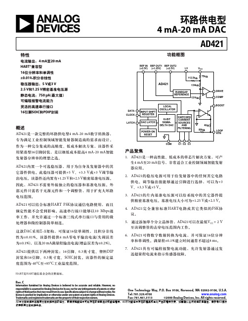
这款DAC采用Σ-Δ架构,可保证16位单调性,且积分非线 性为±0.01%。该器件提供4 mA零电平输出电流(失调误差 为±0.1%),以及20 mA满量程输出电流(增益误差为±0.2%)。
单位
条件/注释
精度 分辨率 单调性 积分非线性 失调(4 mA)(+25°C时)4 失调漂移 典型输出误差(20 mA) (+25°C时)4 总输出漂移 VCC电源灵敏度
16 16 ± 0.01 ± 0.1 ± 25 ± 0.2 ± 50 50
位 位(最小值) % FS(最大值) % FS(最大值) ppm FS/°C(最大值) % FS(最大值) ppm FS/°C(最大值) nA/mV(最大值)
FS = 满量程输出电流 VCC = 5 V 包括片内基准电压漂移 VCC = 5 V 包括片内基准电压漂移 25 nA/mV(典型值)
基准电压源 REF OUT2 输出电压 温漂
外部电流 VCC电源灵敏度 输出阻抗 噪声(0.1 Hz–10 Hz) REF OUT1
输出电压 温漂
外部电流 VCC电源灵敏度 输出阻抗 噪声(0.1 Hz–10 Hz) REF IN 输入电阻
7. AD421具有可编程报警电流功能,允许发射器通过发 送超量程电流来指示传感器故障。
HART是HART通信基金会的注册商标。
Rev. C
Information furnished by Analog Devices is believed to be accurate and reliable. However, no responsibility is assumed by Analog Devices for its use, nor for any infringements of patents or other rightsofthirdpartiesthatmayresultfromitsuse.Speci cationssubjecttochangewithoutnotice.No license is granted by implication or otherwise under any patent or patent rights of Analog Devices. Trademarks and registered trademarks are the property of their respective owners.
UE开关资料120series中文

120-B -03性能特点.Class I, Div.1 & 2, Groups B, C & D Class II, Div. 1 & 2,Groups E,F & G Class III.有一个或二个单刀双掷(SPDT)开关,可选双刀双掷(DPDT)开关 .双端电器接口输出,方便连线.焊接膜片或波纹管.端子连线方式.开关盖有锁定功能.有微压及微差压开关压力,真空,差压开关和温度开关U N I T E D E L E C T R I CC O N T R O L S120 Series120 Series120 Series2 w w w .u e o n l i n e .c o m 120-B -03在选择工业用压力或温度开关时,经常要考虑其安全性能。
120系列产品满足了UL、CSA、ATEX等标准,可用于爆炸区域及含有强腐蚀气体环境中对设备和人员安全的保护。
120系列可以提供不同的压力,差压,真空和温度范围,同样可以提供不同的连接方式,各种不同的材料以及感压元件类型,正是由于这种灵活的选择方式使的120系列可广泛应用于各种场所,如化工,石化,炼油,油田,钻井平台,输油管线以及制药等各种工业过程。
从1931年开始,作为检测和开关技术的创始者和改革者,UE公司始终坚持把对设备,过程系统和人员的安全保护放在首位。
概要• 符合ANSI标准的法兰可 选用哈氏合金,蒙乃尔 和钽等材料 • 可选带指示的差压开关• 大部分的产品可即时供 货120 S e r i e sUltra-low "wcmodel with welded stainless steel diaphragm Differential pressure model with Option M210, Indicating moduleRemote bulb and armored capillary temperature model Welded stainless steel diaphragm pressure model技术参数储存温度 -65 to 160℉(-54—71℃)环境温度 -58 to 160℉(-50 to 71℃);36-39型,520-525型,540-548型,701-705型:0 to 160℉(-17 to 71℃);820E型,822E型:-40 to 160℉(-40 to 71℃) 环境温度每变化50℉(28℃),设定点典型漂移值小于全量程的1%,E121和E122型,漂移值小于2%。
TPS64201中文资料

ORDERING INFORMATION PLASTIC SOT23-6V I = 3.8 V,V O = 1.2 V,R L = 1.2 Ω,T A = 25°CV OI (coil)I O = 1000 mAFigure 152 m s/DivFigure 16V OV IV I = 3.8 V to 5 V,V O = 1.2 V,R L = 1.2 Ω,T A = 25°C40 m s/DivFigure 17V OI OV I = 5 V,V O = 3.3 V,I L = 200 mA to 1800 mA,T A = 25°CTPS64203LOAD TRANSIENT RESPONSE50 m s/DivENV OI II(Inductor)V I = 3.8 V,V O = 3.3 V,R L = 1.66 Ω,T A = 25°C100 m s/DivFigure 18 DETAILED DESCRIPTIONIMPORTANT NOTICETexas Instruments Incorporated and its subsidiaries (TI) reserve the right to make corrections, modifications, enhancements, improvements, and other changes to its products and services at any time and to discontinue any product or service without notice. Customers should obtain the latest relevant information before placing orders and should verify that such information is current and complete. All products are sold subject to TI’s terms and conditions of sale supplied at the time of order acknowledgment.TI warrants performance of its hardware products to the specifications applicable at the time of sale in accordance with TI’s standard warranty. T esting and other quality control techniques are used to the extent TI deems necessary to support this warranty. Except where mandated by government requirements, testing of all parameters of each product is not necessarily performed.TI assumes no liability for applications assistance or customer product design. Customers are responsible for their products and applications using TI components. T o minimize the risks associated with customer products and applications, customers should provide adequate design and operating safeguards.TI does not warrant or represent that any license, either express or implied, is granted under any TI patent right, copyright, mask work right, or other TI intellectual property right relating to any combination, machine, or process in which TI products or services are used. Information published by TI regarding third-party products or services does not constitute a license from TI to use such products or services or a warranty or endorsement thereof. Use of such information may require a license from a third party under the patents or other intellectual property of the third party, or a license from TI under the patents or other intellectual property of TI.Reproduction of information in TI data books or data sheets is permissible only if reproduction is without alteration and is accompanied by all associated warranties, conditions, limitations, and notices. Reproduction of this information with alteration is an unfair and deceptive business practice. TI is not responsible or liable for such altered documentation.Resale of TI products or services with statements different from or beyond the parameters stated by TI for that product or service voids all express and any implied warranties for the associated TI product or service and is an unfair and deceptive business practice. TI is not responsible or liable for any such statements. Following are URLs where you can obtain information on other Texas Instruments products and application solutions:Products ApplicationsAmplifiers Audio /audioData Converters Automotive /automotiveDSP Broadband /broadbandInterface Digital Control /digitalcontrolLogic Military /militaryPower Mgmt Optical Networking /opticalnetwork Microcontrollers Security /securityTelephony /telephonyVideo & Imaging /videoWireless /wirelessMailing Address:Texas InstrumentsPost Office Box 655303 Dallas, Texas 75265Copyright 2004, Texas Instruments Incorporated。
P6421-FP120中文资料

Switch Positions Order PPR’s Model PPR’s Available With This Model
SW1 SW2 SW1 SW2 SW1 SW2 SW1 SW2
SW1
SW2
SW5
CCW
120 192 300 360 400 480 500 512 540 600 720 960 1000 1024 30, 60, 120, 240, 480 48, 96, 192, 384, 768 75, 150, 300, 600, 1200 90, 180, 360, 720, 1440 100, 200, 400, 800, 1600 120, 240, 480, 960, 1920 125, 250, 500, 1000, 2000 128, 256, 512, 1024, 2048 135, 270, 540, 1080, 2160 150, 300, 600, 1200, 2400 180, 360, 720, 1440, 2880 240, 480, 960, 1920, 3840 250, 500, 1000, 2000, 4000 256, 512, 1024, 2048, 4096
P 4 or 6 X X X — A X
Shaft Diameter Order Choice 1=1/4" diameter 2=5/16" diameter 3=3/8" diameter 4=1/2" diameter Shaft Extension Order Choice 1=Single extension 2=Double extension Mounting Type Order Choice 1=2.0" B.H.C. 2=Flanged base (mounting type can be changed by substituting bottom plate when programming) Channel Types Are: Q=Quadrature outputs* P=Separate UP & DOWN output channels U=Pulse train output with UP/DN direction output S=Single output channel Channel Types Programming Channel Outputs Order Choice A=NPN w/pullup res. B=NPN open collector F=5V NPN w/pullup res. G=5V NPN open collector H=PNP outputs K=5V line driver L=8-15V line driver Type SW3 Q S CCW CCW P Cntr U S CW CW Cntr SW4
- 1、下载文档前请自行甄别文档内容的完整性,平台不提供额外的编辑、内容补充、找答案等附加服务。
- 2、"仅部分预览"的文档,不可在线预览部分如存在完整性等问题,可反馈申请退款(可完整预览的文档不适用该条件!)。
- 3、如文档侵犯您的权益,请联系客服反馈,我们会尽快为您处理(人工客服工作时间:9:00-18:30)。
60PPR 96PPR 150PPR 180PPR 200PPR 240PPR 250PPR 256PPR 270PPR 300PPR 360PPR 480PPR 500PPR 512PPR
120PPR 192PPR 300PPR 360PPR 400PPR 480PPR 500PPR 512PPR 540PPR 600PPR 720PPR 960PPR 1000PPR 1024PPR
One Encoder Can Provide Over 20 Model Variations...
Select Pulse Width Select PPR’s
Select Channels
SW1
SW2
SW3
SW4
SW5 on bottom
Simply remove the bottom panel and set the switches for the functions desired.
240PPR 384PPR 600PPR 720PPR 800PPR 960PPR 1000PPR 1024PPR 1080PPR 1200PPR 1440PPR 1920PPR 2000PPR 2048PPR
7
Programming of Switches: \CCW=set to left; | Cntr=set center; /CW=set to right Note: for SW5 (right hand column PPR x 4) Time Settings: CW=other columns; Cntr=5-10µsec; CCW=25-35µsec
0600
Encoders to be shipped with the PPR as ordered & quadrature channel type with 50/50 duty cycle pulse. *Quadrature available for 1st three SW 1 & 2 columns (below).
P 4 or 6 X X X — A X
Shaft Diameter Order Choice 1=1/4" diameter 2=5/16" diameter 3=3/8" diameter 4=1/2" diameter Shaft Extension Order Choice 1=Single extension 2=Double extension Mounting Type Order Choice 1=2.0" B.H.C. 2=Flanged base (mounting type can be changed by substituting bottom plate when programming) Channel Types Are: Q=Quadrature outputs* P=Separate UP & DOWN output channels U=Pulse train output with UP/DN direction output S=Single output channel Channel Types Programming Channel Outputs Order Choice A=NPN w/pullup res. B=NPN open collector F=5V NPN w/pullup res. G=5V NPN open collector H=PNP outputs K=5V line driver L=8-15V line driver Type SW3 Q S CCW CCW P Cntr U S CW CW Cntr SW4
CCW
Cntr
CCW
CW
CCW
CW
Cntr
00PPR 1440PPR 1600PPR 1920PPR 2000PPR 2048PPR 2160PPR 2400PPR 2880PPR 3840PPR 4000PPR 4096PPR
CCW
30PPR 48PPR 75PPR 90PPR 100PPR 120PPR 125PPR 128PPR 135PPR 150PPR 180PPR 240PPR 250PPR 256PPR
H e r c u l e s
6000 Series
4000 Series
For the latest specifications visit our website
元器件交易网
Hercules Encoders “Value Added” Programmable Encoder
6
Series 4000 and 6000 Programmable Encoders
Standard Features • 4000 Series - Space-Saving Enclosure, 1-1/2"D x 3"H x 3"W, 25 to 4096 PPR. • 6000 Series - Internal Space for 3 Separate Encoders, 25 to 4096 PPR. • Built-In Anti-Jitter Circuitry. • Operating Voltage Flexibility - 8 to 28Vdc, 5Vdc with TTL Outputs and Line Drivers, etc. • Low Supply Current Requirements - Only 50 Milliamperes per Encoder • Extra Heavy Duty 1/2"D Shafts - Optional
Switch Positions Order PPR’s Model PPR’s Available With This Model
SW1 SW2 SW1 SW2 SW1 SW2 SW1 SW2
SW1
SW2
SW5
CCW
120 192 300 360 400 480 500 512 540 600 720 960 1000 1024 30, 60, 120, 240, 480 48, 96, 192, 384, 768 75, 150, 300, 600, 1200 90, 180, 360, 720, 1440 100, 200, 400, 800, 1600 120, 240, 480, 960, 1920 125, 250, 500, 1000, 2000 128, 256, 512, 1024, 2048 135, 270, 540, 1080, 2160 150, 300, 600, 1200, 2400 180, 360, 720, 1440, 2880 240, 480, 960, 1920, 3840 250, 500, 1000, 2000, 4000 256, 512, 1024, 2048, 4096
元器件交易网
Hercules Encoders
Programmable
Incremental Encoders
Select PPR’s Choice of 5 PPR’s Select Pulse Width 10µSecs, 30µSecs or Square Wave Select Channels •Single or quadrature channels •Count with up/down direction •Up count channel and down count channel Function Selection Switches SW1 SW2 SW3 SW4 SW5 on bottom