HLMP-KB45-F00DD中文资料
HLMP-345X中文资料
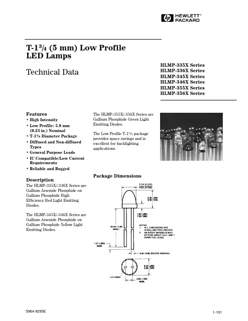
1-101HT-13/4 (5 mm) Low Profile LED Lamps Technical DataFeatures• High Intensity• Low Profile: 5.8 mm (0.23in.) Nominal• T-13/4 Diameter Package • Diffused and Non-diffused Types• General Purpose Leads• IC Compatible/Low Current Requirements• Reliable and RuggedDescriptionThe HLMP-335X/-336X Series are Gallium Arsenide Phosphide on Gallium Phosphide HighEfficiency Red Light Emitting Diodes.The HLMP-345X/-346X Series are Gallium Arsenide Phosphide on Gallium Phosphide Yellow Light Emitting Diodes.The HLMP-355X/-356X Series are Gallium Phosphide Green Light Emitting Diodes.The Low Profile T-13/4 package provides space savings and is excellent for backlighting applications.Package DimensionsHLMP-335X Series HLMP-336X Series HLMP-345X Series HLMP-346X Series HLMP-355X Series HLMP-356X Series5964-9295E1-1021-103Electrical Specifications at T A = 25°CDevice Test Symbol Description HLMP-Min.Typ.Max.Units Conditions I VAxial Luminous Intensity3350 2.1 3.5mcdI F = 10 mA 3351 5.47.0(Figure 8)33658.610.0336613.818.02θ1/2Including Angle Between Half 335050Deg.Note 1 (Figure 11)Luminous Intensity Points335150336545336645λPEAK Peak Wavelength 635nm Measurement at Peak (Figure 1)λd Dominant Wavelength 626nm Note 2∆λ1/2Spectral Line Halfwidth 40nm τs Speed of Response 90ns C Capacitance 11pF V F = 0; f = 1 MHz R θJ-PIN Thermal Resistance 260°C/W Junction to Cathode Lead V F Forward Voltage1.92.4V I F = 10 mA (Figure 7)V R Reverse Breakdown Voltage 5.0V I R = 100 µA ηVLuminous Efficacy145lm/WNote 3High Efficiency Red HLMP-335X/-336X Series Notes:1. θ1/2 is the off-axis angle at which the luminous intensity is half the axial luminous intensity.2. Dominant wavelength, λd , is derived from the CIE chromaticity diagram and represents the single wavelength which defines the color of the device.3. Radiant Intensity, I e , in watts/steradian may be found from the equation I e = I v /ηv , where I v is the luminous intensity in candelas and ηv is the luminous efficacy in lumens/watt.Figure 8. Relative Luminous Intensity vs. Forward Current.Figure 7. Forward Current vs.Forward Voltage.Figure 9. Relative Efficiency(Luminous Intensity per Unit Current)vs. Peak Current.1-104Figure 10. Maximum Tolerable Peak Current vs. Pulse Duration. (I DC MAX as per MAX Ratings).Figure 11. Relative Luminous Intensity vs. Angular Displacement.Electrical Specifications at T A = 25°CDevice Test Symbol Description HLMP-Min.Typ.Max.Units Conditions I VAxial Luminous Intensity3450 2.2 4.0mcdI F = 10 mA 34515.710.0(Figure 13)3465 5.712.034669.218.02θ1/2Including Angle Between Half 345050Deg.Note 1 (Figure 16)Luminous Intensity Points345150346545346645λPEAK Peak Wavelength 583nm Measurement at Peak (Figure 1)λd Dominant Wavelength 585nm Note 2∆λ1/2Spectral Line Halfwidth 36nm τs Speed of Response 90ns C Capacitance 15pF V F = 0; f = 1 MHz R θJ-PIN Thermal Resistance 260°C/W Junction to Cathode Lead V F Forward Voltage2.02.4V I F = 10 mA (Figure 12)V R Reverse Breakdown Voltage 5.0V I R = 100 µA ηVLuminous Efficacy500lm/WNote 3Yellow HLMP-345X/-346X SeriesNotes:1. θ1/2 is the off-axis angle at which the luminous intensity is half the axial luminous intensity.2. Dominant wavelength, λd , is derived from the CIE chromaticity diagram and represents the single wavelength which defines the color of the device.3. Radiant Intensity, I e , in watts/steradian may be found from the equation I e = I v /ηv , where I v is the luminous intensity in candelas and ηv is the luminous efficacy in lumens/watt.1-105Figure 15. Maximum Tolerable Peak Current vs. Pulse Duration. (I DC MAX as per MAX Ratings).Figure 16. Relative Luminous Intensity vs. Angular Displacement.Figure 13. Relative Luminous Intensity vs. Forward Current.Figure 14. Relative Efficiency(Luminous Intensity per Unit Current)vs. Peak Current.Figure 12. Forward Current vs.Forward Voltage.605040302010V – FORWARD VOLTAGE – V FI – F O R W A R D C U RRE N T – m AF1-106Electrical Specifications at T A = 25°CDevice Test Symbol Description HLMP-Min.Typ.Max.Units Conditions I VAxial Luminous Intensity3553 1.6 3.2mcdI F = 10 mA 3554 6.710.0(Figure 18)35674.27.0356810.615.02θ1/2Including Angle Between Half 355350Deg.Note 1 (Figure 21)Luminous Intensity Points355450356740356840λPEAK Peak Wavelength 565nm Measurement at Peak (Figure 1)λd Dominant Wavelength 569nm Note 2∆λ1/2Spectral Line Halfwidth 28nm τs Speed of Response 500ns C Capacitance 18pF V F = 0; f = 1 MHz R θJ-PIN Thermal Resistance 260°C/W Junction to Cathode Lead V F Forward Voltage2.12.7V I F = 10 mA (Figure 17)V R Reverse Breakdown Voltage 5.0V I R = 100 µA ηVLuminous Efficacy595lm/WNote 3Green HLMP-355X/-356X SeriesNotes:1. θ1/2 is the off-axis angle at which the luminous intensity is half the axial luminous intensity.2. Dominant wavelength, λd , is derived from the CIE chromaticity diagram and represents the single wavelength which defines the color of the device.3. Radiant Intensity, I e , in watts/steradian may be found from the equation I e = I v /ηv , where I v is the luminous intensity in candelas and ηv is the luminous efficacy in lumens/watt.Figure 17. Forward Current vs.Forward Voltage.Figure 19. Relative Efficiency (Luminous Intensity per Unit Current) vs. Peak Current.Figure 18. Relative Luminous Intensity vs. Forward Current.1-107Figure 20. Maximum Tolerable Peak Current vs. Pulse Duration. (I DC MAX as per MAX Ratings).Figure 21. Relative Luminous Intensity vs. Angular Displacement.。
HLMP-CM26-Q0DDD中文资料
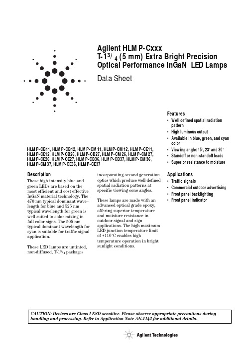
Agilent HLMP-CxxxT-13/4 (5mm) Extra Bright Precision Optical Performance InGaN LED Lamps Data SheetDescriptionThese high intensity blue and green LEDs are based on the most efficient and cost effective InGaN material technology. The 470 nm typical dominant wave–length for blue and 525 nm typical wavelength for green is well suited to color mixing in full color signs. The 505 nm typical dominant wavelength for cyan is suitable for traffic signal application.These LED lamps are untinted, non-diffused, T-13/4 packagesFeatures•Well defined spatial radiationpattern•High luminous output•Available in blue, green, and cyancolor•Viewing angle: 15°, 23°and 30°•Standoff or non-standoff leads•Superior resistance to moistureApplications•Traffic signals•Commercial outdoor advertising•Front panel backlighting•Front panel indicator incorporating second generationoptics which produce well-definedspatial radiation patterns atspecific viewing cone angles.These lamps are made with anadvanced optical grade epoxy,offering superior temperatureand moisture resistance inoutdoor signal and signapplications. The high maximumLED junction temperature limitof +110°C enables hightemperature operation in brightsunlight conditions.HLMP-CB11, HLMP-CB12, HLMP-CM11, HLMP-CM12, HLMP-CE11,HLMP-CE12, HLMP-CB26, HLMP-CB27, HLMP-CM26, HLMP-CM27,HLMP-CE26, HLMP-CE27, HLMP-CB36, HLMP-CB37, HLMP-CM36,HLMP-CM37, HLMP-CE36, HLMP-CE37CAUTION: Devices are Class I ESD sensitive. Please observe appropriate precautions during handling and processing. Refer to Application Note AN-1142 for additional details.Package DimensionsPackage APackage B5.80 ± 0.20(0.228 ±∅ CATHODEFLATMIN.SQ. TYP.NOTES:1. MEASURED JUST ABOVE FLANGE.2. ALL DIMENSIONS ARE IN MILLIMETERS (INCHES).3. EPOXY MENISCUS MAY EXTEND ABOUT 1 mm (0.040") DOWN THE LEADS.4. IF HEAT SINKING APPLICATION IS REQUIRED, THE TERMINAL FOR HEAT SINK IS ANODE.Device Selection GuideTypicalViewing Angle,Intensity (cd) at 20 mA PackagePart Number Color2q1/2 (Degree)Min.Max.Standoff Dimension Lens HLMP-CB11-TW0xx Blue15 2.57.2No A Clear HLMP-CB11-UVAxx Blue15 3.2 5.5No A Clear HLMP-CB12-TW0xx Blue15 2.57.2Yes B Clear HLMP-CM11-Y20xx Green159.327.0No A Clear HLMP-CM11-Z1Cxx Green1512.021.0No A Clear HLMP-CM12-Y20xx Green159.327.0Yes B Clear HLMP-CE11-X10xx Cyan157.221.0No A Clear HLMP-CE12-X10xx Cyan157.221.0Yes B Clear HLMP-CB26-SV0xx Blue23 1.9 5.5No A Clear HLMP-CB26-TUDxx Blue23 2.5 4.2No A Clear HLMP-CB27-SV0xx Blue23 1.9 5.5Yes B Clear HLMP-CM26-X10xx Green237.221.0No A Clear HLMP-CM26-YZCxx Green239.316.0No A Clear HLMP-CM27-X10xx Green237.221.0Yes B Clear HLMP-CE26-WZ0xx Cyan23 5.516.0No A Clear HLMP-CE27-WZ0xx Cyan23 5.516.0Yes B Clear HLMP-CB36-QT0xx Blue30 1.15 3.2No A Clear HLMP-CB36-RSAxx Blue30 1.5 2.5No A Clear HLMP-CB37-RU0xx Blue30 1.5 4.2Yes B Clear HLMP-CB37-RSDxx Blue30 1.5 2.5Yes B Clear HLMP-CM36-X10xx Green307.221.0No A Clear HLMP-CM36-XYCxx Green307.212.0No A Clear HLMP-CM37-X10xx Green307.221.0Yes B Clear HLMP-CM37-XYCxx Green307.212.0Yes B Clear HLMP-CM37-XYDxx Green307.212.0Yes B Clear HLMP-CE36-WZ0xx Cyan30 5.516.0No A Clear HLMP-CE37-WZ0xx Cyan30 5.516.0Yes B ClearNotes:1.Tolerance for luminous intensity measurement is ±15%.2.The luminous intensity is measured on the mechanical axis of the lamp package.3.The optical axis is closely aligned with the package mechanical axis.4.LED light output is bright enough to cause injuries to the eyes. Precautions must be taken to prevent looking directly at the LED without propersafety equipment.5. 2q1/2 is the off-axis angle where the luminous intensity is 1/2 the on-axis intensity.Part Numbering SystemHLMP-x x xx-x x x xxMechanical Options00: BulkDD: Ammo PackColor Bin Options0: Full Color Bin DistributionA: Color Bin 1 and 2C: Color Bin 3 and 4D: Color Bin 4 and 5Maximum Intensity Bin0: No Maximum Intensity Bin LimitationOthers: Refer to Device Selection GuideMinimum Intensity BinRefer to Device Selection GuideViewing Intensity Bin11: 15° Without Standoff12: 15°With Standoff26: 23°Without Standoff27: 23°With Standoff36: 30°Without standoff37: 30°With StandoffColorB: Blue 470 nmM: Green 525 nmE: Cyan 505 nmPackageC: T-13/4 (5 mm) Round LampAbsolute Maximum Rating at T A = 25°CParameters Value UnitDC Forward Current [1]30mAPeak Pulsed Forward Current[3]100mAAverage Forward Current30mAPower Dissipation120mWLED Junction Temperature110°COperating Temperature Range–40 to +85°CStorage Temperature Range–40 to +100°CWave Soldering Temperature[2]250 for 3 secs°CNotes:1.Derate linearly as shown in Figure2.2.1.59 mm (0.060 inch) below body.3.Duty factor 10%, frequency 1 KHz.Electrical/Optical CharacteristicsT A = 25o CBlue Green CyanParameters Symbol Min.Typ.Max.Min.Typ.Max.Min.Typ.Max.Units Test Condition Forward Voltage V F 3.5 4.0 3.6 4.0 3.5 4.0V I F = 20 mA Reverse Voltage[1]V R 5.0 5.0 5.0V I R = 10 µA Thermal Resistance R q J-PIN240240240o C/W LED Junction toAnode Lead Dominant l d460470480520525540490505510nm I F = 20 mA Wavelength[2]Peak Wavelength l PEAK464516501nm Peak of Wavelengthof Spectral Distribu-tion at I F = 20 mA Spectral Half Width Dl1/2233230nm Wavelength Widthat Spectral Distribu-tion Power Pointat I F = 20 mA Luminous Efficacy[3]h v74484319lm/W Emitted LuminousPower/EmittedRadiant Power Notes:1.The reverse voltage of the product is equivalent to the forward voltage of the protective chip at I R = 10 µA.2.The dominant wavelength, l d, is derived from the Chromaticity Diagram and represents the color of the lamp.3.The radiant intensity, Ie in watts/steradian, may be found from the equation Ie = Iv/h v, where Iv is the luminous intensity in candelas and h v is theluminous efficacy in lumens/watt.Figure 5. Relative intensity vs. DC forward current.Figure 4. Relative dominant wavelength vs. DC forward current.DC FORWARD CURRENT – mAR E L A T I V E D O M I N A N T W A V E L E N G T H (N O R M A L I Z E D A T 20 m A )1020301.0250.9901.0151.0201.0101.0051.0000.995GREENBLUER E L A T I V E I N T E N S I T Y (N O R M A L I Z E D A T 20 m A )FORWARD CURRENT – mAFigure 1. Relative intensity vs. wavelength.Figure 3. Forward current vs. forward voltage.Figure 2. Forward current vs. ambient temperature.WAVELENGTH – nmR E L A T I V E I N T E N S I T Y1.0000.800.600.400.20030103.0202.01.0F O R W A R D C U R R E N T – m AFORWARD VOLTAGE – V 4.0CYANGREENBLUEI F – F O R W A R D C U R R E N T – m AV F – FORWARD VOLTAGE – VOLTSFigure 6. Spatial radiation pattern for Cx11 and Cx12.R E L A T I V E L U M I N O U S I N T E N S I T Y10ANGULAR DISPLACEMENT – DEGREES0.5-90-600-30306090Figure 7. Spatial radiation pattern for Cx26 and Cx27.Figure 8. Spatial radiation pattern for Cx36 and Cx37.R E L A T I V E L U M I N O U S I N T E N S I T Y10ANGULAR DISPLACEMENT – DEGREES0.5-90-600-30306090R E L A T I V E L U M I N O U S I N T E N S I T Y10ANGULAR DISPLACEMENT – DEGREES0.5-90-600-30306090Intensity Bin Limit TableIntensity (mcd) at 20 mA Bin Min MaxN680880P8801150Q11501500R15001900S1*******T25003200U32004200V42005500W55007200X72009300Y930012000Z1200016000 11600021000 Tolerance for each bin limit is ±15%.Blue Color Bin TableBin Min Dom Max Dom Xmin Ymin Xmax Ymax 1460.0464.00.14400.02970.17660.09660.18180.09040.13740.0374 2464.0468.00.13740.03740.16990.10620.17660.09660.12910.0495 3468.0472.00.12910.04950.16160.12090.16990.10620.11870.0671 4472.0476.00.11870.06710.15170.14230.16160.12090.10630.0945 5476.0480.00.10630.09450.13970.17280.15170.14230.09130.1327 Tolerance for each bin limit is ±0.5 nm.Cyan Color Bin TableBin Min Dom Max Dom Xmin Ymin Xmax Ymax 1490.0495.00.04540.29450.11640.38890.13180.3060.02350.4127 2495.0500.00.03450.41270.10570.47690.11640.38890.00820.5384 3500.0505.00.00820.53840.10270.55840.10570.47690.00390.6548 4505.0510.00.00390.65480.10970.62510.10270.55840.01390.7502 7498.0503.00.01320.48820.10280.52730.10920.44170.00400.6104 8503.0508.00.00400.61040.10560.60070.10280.52730.00800.7153 Tolerance for each bin limit is ±0.5 nm.Green Color Bin TableBin Min Dom Max Dom Xmin Ymin Xmax Ymax 1520.0524.00.07430.83380.18560.65560.16500.65860.10600.8292 2524.0528.00.10600.82920.20680.64630.18560.65560.13870.8148 3528.0532.00.13870.81480.22730.63440.20680.64630.17020.7965 4532.0536.00.17020.79650.24690.62130.22730.63440.20030.7764 5536.0540.00.20030.77640.26590.60700.24690.62130.22960.7543 Tolerance for each bin limit is ±0.5 nm./semiconductors For product information and a complete list of distributors, please go to our web site.For technical assistance call:Americas/Canada: +1 (800) 235-0312 or (916) 788-6763Europe: +49 (0) 6441 92460China: 10800 650 0017Hong Kong: (+65) 6756 2394India, Australia, New Zealand: (+65) 6755 1939 Japan: (+81 3) 3335-8152(Domestic/Interna-tional), or 0120-61-1280(Domestic Only) Korea: (+65) 6755 1989Singapore, Malaysia, Vietnam, Thailand, Philippines, Indonesia: (+65) 6755 2044 Taiwan: (+65) 6755 1843Data subject to change.Copyright © 2004 Agilent Technologies, Inc. December 7, 20045989-1022EN。
海利普空压机变频器HLP-SK说明书
375 544 715 375
400 582 765 400
415 604 795 415
-6-
HLP-SK 空压机专用变频器使用说明书
HLP-SK系列
2、产品通用规格
项目名称
HLP-SK
控制方式
SVPWM
输入电源
380V电源:-20% - 10% (-20% 建议降档使用)
五位数码显示 及状态指示灯
HLP-AS系K系列列
4、故障及分析
72
十一、周边设施选用及配置
74
1、选件
74
2、配置
75
十二、附录
77
附录一 简单应用举例
77
附录二 外形及安装尺寸
81
附录三 键盘外形及安装尺寸
83
附录四 例HLP-SK变频器参数设置说明
84
附录五 使用者记录及反馈
85
SVPWM
ห้องสมุดไป่ตู้电压空间矢量
转矩控制
可设定转矩提升,最大10.0% ,启动转矩在1.0Hz时可 达150%
一 般
多功能输入端
6个多功能输入端,实现8段速控制、程序运行、4段加减 速切换、UP、DOWN机能、计数器、外部急停等功能
控 制
多功能输出端
有5个多功能输出端,实现运转中、零速、计数器、外部 异常、程序运行等指示及报警
● 在变频器输入前端接入接触器,控制变频器的起动或停止会影响 变频器的寿命,一般要求 通过 F OR或R E V端子来控制,在起、停 较为频繁场所,应特别注意使用。
● 变频器电源,请使用独立电源,绝对避免与电焊机等强干扰设备 共用同一电源,否则会引起变频器保护或变频器损坏。
2、送电中
HLMP-C615-M0000中文资料

DescriptionThese non-diffused lamps are designed to produce a bright light source and smooth radiationpattern. A slight tint is added to the lens for easy color identification.This lamp has been designed with aHLMP-C115, HLMP-C117, HLMP-C123, HLMP-C215, HLMP-C223,HLMP-C315, HLMP-C323, HLMP-C415, HLMP-C423, HLMP-C515,HLMP-C523, HLMP-C615, HLMP-C623Features•Very high intensity •Exceptional uniformity •Microtint lens for color identification•Consistent viewability All colors: AlGaAs RedHigh Efficiency Red Yellow Orange GreenEmerald Green •15° and 25° family•Tape and reel options available •Binned for color and intensity Applications•Ideal for backlighting front panels*•Used for lighting switches •Adapted for indoor and outdoor signsAgilentT-13/4 Super Ultra-Bright LED LampsData Sheet20mil lead frame, enhanced flange, and tight meniscus controls, making it compatible with radial lead automated insertion equipment.Selection GuidePart Number Luminous Intensity Iv (mcd) Color2θ1/2[1]Standoff Leads HLMP-Min.Max.DH AS AlGaAs15No C115290.0–C115-O00xx290.0–C115-OP0xx290.01000.0Yes C117-OP0xx290.01000.025No C12390.2–C123-L00xx90.2–Red15No C215138.0–C215-M00xx138.0–C215-MN0xx138.0400.025No C22390.2–C223-L00xx90.2–C223-MN0xx138.0400.0 Yellow15No C315147.0–C315-L00xx147.0–C315-LM0xx147.0424.025No C32396.2–C323-K00xx96.2–C323-KL0xx96.2294.0 Orange15No C415138.0–C415-M00xx138.0–C415-M0D0xx138.0–C415-MN0xx138.0400.025No C42390.2–C423-L00xx90.2–C423-LM0xx90.2276.0 Green15No C515170.0–C515-L00xx170.0C515-LM0xx170.0490.025No C52369.8–C523-J00xx69.8–C523-KL0xx111.7340.0 Emerald Green15No C61517.0–C615-G00xx17.0–25No C623 6.7–C623-E00xx 6.7–Part Numbering SystemHLMP - C x xx - x x x xxMechanical Options00: Bulk01: Tape & Reel, Crimped Leads02: Tape & Reel, Straight LeadsB2: Right Angle Housing, Even LeadsUQ: Ammo Pack, Horizontal LeadsColor Bin Options0: Full Color Bin DistributionD: Color Bins 4 & 5 onlyMaximum Iv Bin Options0: Open (No Maximum Limit)Others: Please refer to the Iv Bin TableMinimum Iv Bin OptionsPlease refer to the Iv Bin TableViewing Angle & Standoffs Options15: 15 Degree, without Standoffs17: 15 Degree, with Standoffs23: 25 Degree, without StandoffsColor Options1. AS AlGaAs Red2. High Efficiency Red3. Yellow4. Orange5. Green6. Emerald GreenPackage OptionsC: T-1 3/4 (5 mm)Absolute Maximum Ratings at T A = 25°CHighHighDH AS Efficiency Performance AlGaAs Red and Green and ParameterRed Orange Yellow Emerald Green Units DC Forward Current [1]30302030mA Transient Forward Current [2]500500500500mA (10 µsec Pulse)Reverse Voltage (Ir = 100 µA)5555V LED Junction Temperature 110110110110°C Operating Temperature Range –20 to +100–55 to +100–20 to +100°C Storage Temperature Range –55 to +100°CWave Soldering Temperature 250°C for 3 seconds [1.59 mm (0.063 in.) from body]Lead Solder Dipping Temperature 260°C for 5 seconds[1.59 mm (0.063 in.) from body]Notes:1. See Figure 5 for maximum current derating vs. ambient temperature.2. The transient current is the maximum nonrecurring peak current the device can withstand without damaging the LED die and wire bond.Package DimensionsHLMP-Cx15 and HLMP-Cx23HLMP-Cx17(0.039)NOTES:1. ALL DIMENSIONS ARE IN MILLIMETERS (INCHES).2. LEADS ARE MILD STEEL, SOLDER DIPPED.3. AN EPOXY MENISCUS MAY EXTEND ABOUT 0.5 mm (0.020 in.) DOWN THE LEADS.± 0.20± 0.008)Electrical Characteristics at T A = 25°CForward Reverse Capacitance Speed of ResponseVoltage Breakdown C (pF)Thermalτs (ns)Vf (Volts)Vr (Volts)Vf = 0Resistance Time Constant@ If = 20 mA@ Ir = 100 µA f = 1 MHz RθJ-PIN e-t/τsPart Number Typ.Max.Min.Typ.(°C/W)Typ.HLMP-C115 1.8 2.253021030HLMP-C117HLMP-C123HLMP-C215 1.9 2.651121090HLMP-C223HLMP-C315 2.1 2.651521090HLMP-C323HLMP-C415 1.9 2.654210280HLMP-C423HLMP-C515 2.2 3.0518210260HLMP-C523HLMP-C615 2.2 3.0518210260HLMP-C623Optical Characteristics at T A = 25°CLuminous Color,ViewingIntensity Peak Dominant Angle LuminousIv (mcd)Wavelength Wavelength2θ1/2Efficacy@ 20 mA[1]λpeak (nm)λd[2] (nm)(Degrees)[3]ηvPart Number Min.Typ.Typ.Typ.Typ.(lm/w) HLMP-C1152906006456371180HLMP-C117HLMP-C1239020026HLMP-C215138300635626171459017023HLMP-C315146300583585175009617025HLMP-C415138300600602173809017023HLMP-C515170300568570205956917028HLMP-C61517455585602065662728Notes:1. The luminous intensity, Iv, is measured at the mechanical axis of the lamp package. The actual peak of the spatial radiation pattern may not bealigned with this axis.2. The dominant wavelength, λd, is derived from the CIE Chromaticity Diagram and represents the color of the device.3. 2θ1/2 is the off-axis angle where the luminous intensity is 1/2 the on-axis intensity.Figure 1. Relative intensity vs. wavelength.Figure 2. Forward current vs. forward voltage (non-resistor lamp).Figure 3. Relative luminous intensity vs. forward current.WAVELENGTH – nmR E L A T I V E I N T E N S I T Y1.00.50I F – F O R W A R DC U R R E N T – m AV F – FORWARD VOLTAGE – VI F – F O R W A R D C U R R E N T – m AV F – FORWARD VOLTAGE – VHIGH EFFICIENCY RED, ORANGE,YELLOW, AND HIGH PERFORMANCEGREEN, EMERALD GREENR E L A T I V E L U M I N O U S I N TE N S I T Y (N O R M A L I Z E D A T 20 m A )I F – DC FORWARD CURRENT – mA R E L A T I V E L U M I N O U S I N T E N S I T Y (N O R M A L I Z E D A T 20 m A )0I DC – DC CURRENT PER LED – mA10201.60.80.4515301.2250.20.61.01.4HER, ORANGE, YELLOW, AND HIGH PERFORMANCE GREEN, EMERALD GREENFigure 5. Maximum forward dc current vs. ambient temperature. Derating based on T j MAX = 110°C.Figure 4. Relative efficiency (luminous intensity per unit current) vs. peak current.Figure 6. Relative luminous intensity vs. angular displacement. 15 degree family.R E L A T I V E E F F I C I E N C Y (N O R M A L I Z E D A T 20 m A )0I PEAK – PEAK FORWARD CURRENT – mA0.60.8300201001.21.00.20.45020010DH As AlGaAs REDηP E A K – R E L A T I V E E F F I C I E N C Y (N O R M A L I Z E D A T 20 m A )I PEAK – PEAK FORWARD CURRENT – mAHER, ORANGE, YELLOW, HIGHPERFORMANCE GREEN, EMERALD GREENI F – F O R W A R D C U R R E NT – m AT A – AMBIENT TEMPERATURE – °C DH As AlGaAs REDI F – F O R W A R D C U R R E N T – m AT A – AMBIENT TEMPERATURE – °CHER, ORANGE, YELLOW, AND HIGH PERFORMANCE GREEN, EMERALD GREEN N O R M A L I Z E D L U M I N O U S I N T E N S I T Y10ANGULAR DISPLACEMENT – DEGREES0.80.60.50.70.2450.10.30.4403530252010515-5-10-15-20-25-30-35-40-450.9Figure 7. Relative luminous intensity vs. angular displacement. 25 degree family.Intensity Bin Limits Intensity Range (mcd)ColorBin Min.Max.L 101.5162.4M 162.4234.6N 234.6340.0O 340.0540.0P 540.0850.0Q 850.01200.0R 1200.01700.0Red/OrangeS 1700.02400.0T 2400.03400.0U 3400.04900.0V 4900.07100.0W 7100.010200.0X 10200.014800.0Y 14800.021400.0Z 21400.030900.0L 173.2250.0M 250.0360.0N 360.0510.0O 510.0800.0P 800.01250.0YellowQ 1250.01800.0R 1800.02900.0S 2900.04700.0T 4700.07200.0U 7200.011700.0V 11700.018000.0W18000.027000.0N O R M A L I Z E D L U M I N O U S I N T E N S I T Y10ANGULAR DISPLACEMENT – DEGREES0.80.60.50.70.2450.10.30.4403530252010515-5-10-15-20-25-30-35-40-450.9Intensity Bin Limits, continuedIntensity Range (mcd) Color Bin Min.Max.E7.612.0F12.019.1G19.130.7H30.749.1I49.178.5J78.5125.7K125.7201.1L201.1289.0 Green/M289.0417.0 Emerald Green N417.0680.0O680.01100.0P1100.01800.0Q1800.02700.0R2700.04300.0S4300.06800.0T6800.010800.0U10800.016000.0V16000.025000.0W25000.040000.0 Maximum tolerance for each bin limit is ± 18%.Color CategoriesLambda (nm)Color Category #Min.Max.6561.5564.55564.5567.5 Green4567.5570.53570.5573.52573.5576.51582.0584.53584.5587.0 Yellow2587.0589.54589.5592.05592.0593.01597.0599.52599.5602.03602.0604.5 Orange4604.5607.55607.5610.56610.5613.57613.5616.58616.5619.5 Tolerance for each bin limit is ± 0.5 nm.Mechanical Option MatrixMechanical Option Code Definition00Bulk Packaging, minimum increment 500 pcs/bag01Tape & Reel, crimped leads, minimum increment 1300 pcs/bag02Tape & Reel, straight leads, minimum increment 1300 pcs/bagB2Right Angle Housing, even leads, minimum increment 500 pcs/bagUQ Ammo Pack, horizontal leads, in 1K minimum incrementNote:All categories are established for classification of products. Products may not be available in all categories. Please contact your local Agilent representative for further clarification/information./semiconductorsFor product information and a complete list ofdistributors, please go to our web site.For technical assistance call:Americas/Canada: +1 (800) 235-0312 or(916) 788-6763Europe: +49 (0) 6441 92460China: 10800 650 0017Hong Kong: (+65) 6756 2394India, Australia, New Zealand: (+65) 6755 1939Japan: (+81 3) 3335-8152 (Domestic/Interna-tional), or 0120-61-1280 (Domestic Only)Korea: (+65) 6755 1989Singapore, Malaysia, Vietnam, Thailand,Philippines, Indonesia: (+65) 6755 2044Taiwan: (+65) 6755 1843Data subject to change.Copyright © 2004 Agilent Technologies, Inc.Obsoletes 5965-6165ENovember 11, 20045988-2149EN。
45系列轴向柱塞泵
45系列轴向柱塞泵45系列开式轴向柱塞泵产品样本45系列开式轴向柱塞泵产品样本版本信息修订历史修订记录表日期 2012年10月 2012年9月 2012年9月 2012年8月 2012年7月 2012年6月 2012年3月 2012年1月 2011年12月 2011年10月页码多页多页多页 14-15, 62 多页 17,23,44,72,92 110 多页 75 多页多页 56 108 多页 45, 50 45 多页 22, 27, 31, 41, 43, 47 34, 28 多页多页 62, 65 58-62 78, 93, 94, 95 32, 74, 75, 92 76 52, 53 27, 50, 72, 89 76 4 多页多页 50 多页 51, 52, 53 修改项目增加电控根据原中文版本及英文版本GO大幅修改多处修正增加补油泵回路,增加S5轴输入轴及辅助安装法兰O型圈尺寸变更删除各排量泵的轴承寿命表删除工作盖板尺寸图添加系统稳定性,20页,型号代码多处更改修改 A2 轴描述多处改变及修改技术规格校订,选型代码校订示意图修改花键啮合尺寸修改通篇多处修改060B最高速度3120,安装法兰修改添加065C, 075C轴承寿命参数多处校订及改变-主要修改多处小修改,添加EJ, EA控制器尺寸去掉L和K型中T2轴选项修改对LS的X口接头深度的警告添加对LS的X口接头深度的警告添加 SAE-C 2螺栓壳体 J型尺寸修改多处小修改,去掉E型S5轴选项示意图修改S2花键宽度修改(仅英制尺寸)示意图修改添加RP 和BP控制的LS设定值必须为20bar 对S2轴-6级,长37.91mm的修改 TOC的修改针对每一型号添加了LS设定范围重新布置F和E型章节,添加排量限制器信息修改负载敏感设定值-增量 bar 去掉G型,添加F型,多处修改修改示意图信息去掉H型,添加J型添加E型添加H型和G型第一次印刷版本 GP GO GN GM GL GK GJ GI GHGG GF GE GD GC GB GA FO FN FM FL FK FJ FI FH FG FG FF FF FE FD FC FB FA E D C B A A45系列开式轴向柱塞泵2011年6月 2011年5月 2011年4月 2011年3月 2011年1月 2010年11月 2010年10月 2009年10月 2009年7月 2009年5月 2009年3月 2008年10月 2008年9月 2008年6月 2008年5月 2008年4月 2008年4月 2008年4月 2008年4月 2008年3月2008年2月2007年11月2007年11月2007年9月2006年11月 2005年8月 2003年4月 2001年5月 1999年5月2012 萨澳-丹佛斯版权所有萨澳-丹佛斯对于其产品样本,手册和其它出版物中可能出现的错误不负任何责任。
罗克韦尔自动化45CRM-4LHTx-D4颜色套传感器用户手册说明书
带 IO-Link 接口的颜色套准标记传感器
45CRM-4LHTx-D4
用户重要须知
在安装、配置、操作或维护设备之前,请仔细阅读本文档及 “ 其他资源” 部分列出的文档,了解设备的 安装、配置和操作信息。除所有适用规范、法规和标准的要求外,用户还应熟悉安装和接线说明。
安装、调整、投入使用、操作、组装、拆卸和维护等活动都应由经过适当培训的人员遵照适用的实施 规程执行。
注册 45CRM IODD . . . . . . . . . . . . . . . . . . . . . . . . . . . . . . . . . . . . . 36
检查 1734-4IOL IO-Link AOP. . . . . . . . . . . . . . . . . . . . . . . . . . . . 45
灼伤危险:位于设备 (例如,驱动器或电机) 表面或内部的标签,提醒人们表面可能存 在高温危险。 弧闪危险:标签可能位于设备上或设备内 (例如电机控制中心),提醒人们可能出 现弧闪。弧闪将造成严重的人身伤害或死亡。请穿戴适当的个人防护设备 (PPE)。遵循 所有安全工作惯例和个人防护设备 (PPE) 的规章要求。
目录
产品概述 . . . . . . . . . . . . . . . . . . . .. . . . . . . . 1
产品介绍 . . . . . . . . . . . . . . . . . . . . . . . . . . . . . . . . . . . . . . . . . . . . . . . . . . . . . . . . . . . . 1 工作模式 . . . . . . . . . . . . . . . . . . . . . . . . . . . . . . . . . . . . . . . . . . . . . . . . . . . . . . . . . . . . 1 特性. . . . . . . . . . . . . . . . . . . . . . . . . . . . . . . . . . . . . . . . . . . . . . . . . . . . . . . . . . . . . . . . . 2 技术参数 . . . . . . . . . . . . . . . . . . . . . . . . . . . . . . . . . . . . . . . . . . . . . . . . . . . . . . . . . . . . 3
HLMP-KB45-G0000中文资料
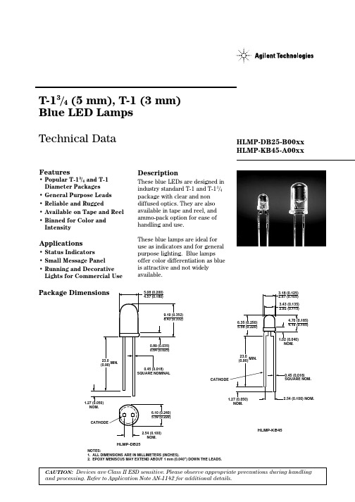
Selection GuideLuminous Intensity Iv (mcd) Part Number Package Viewing Angle Min.Max.HLMP-KB45-A00xx T-14030–HLMP-DB25-B00xx T-1 3/42540–Part Numbering SystemHLMP - x x xx - x x x xxMechanical Option00: Bulk02: Tape & Reel, Straight LeadsDD: Ammo PackColor Bin Options0: Full Color Bin DistributionMaximum Iv Bin Options0: Open (no max. limit)Minimum Iv Bin OptionsPlease refer to the Iv Bin TableViewing Angle25: 25 degrees45: 40 degreesColor OptionsB: Blue 462 nmPackage OptionsD: T-1 3/4 (5 mm)K: T-1 (3 mm)Absolute Maximum Ratings at T A = 25˚CParameter Blue UnitsPeak Forward Current70mADC Current[1]30mAReverse Voltage (I R = 100 µA)5VTransient Forward Current[2]350mA(10 µsec Pulse)LED Junction Temperature115˚COperating Temperature–20 to +80˚CStorage Temperature–30 to +100˚CLead Soldering Temperature 260°C for 5 seconds[1.6 mm (0.063 in.) from body]Notes:1.Derate linearly from 50 °C as shown in Figure 6.2.The transient peak current is the maximum non-recurring peak current that can beapplied to the device without damaging the LED die and wirebond. It is notrecommended that this device be operated at peak currents above the AbsoluteMaximum Peak Forward Current.Optical Characteristics at T A = 25˚CLuminous Color,Viewing Intensity Dominant Peak Angle I V (mcd)Wavelength Wavelength 2θ1/2[2]@ I F = 20 mAλd [1] (nm)λPEAK (nm)Degrees Part Number Typ.Typ.Typ.HLMP-DB25-B00xx 40 10046242625HLMP-KB45-A00xx 30 4546242640Min. Typ.Notes:1.The dominant wavelength, λd , is derived from the CIE chromaticity diagram and represents the single wavelength which defines the color of the device.2. θ1/2 is the off-axis angle at which the luminous intensity is half of the axial luminous intensity.Electrical Characteristics at T A = 25˚CThermal Forward Reverse ResistanceVoltage Breakdown Speed Capacitance R θJ-PIN (°C/W)V F (Volts)V R (Volts)Response C (pF), V F = 0,Junction to Part@ I F = 20 mA @ I R = 100 µA τs (ns) f = 1 MHz Cathode Lead Number Typ. Max. Min. Typ.Typ.Typ.Typ.HLMP-DB25-B00xx 4.0 5.0 5.0 3050097260HLMP-KB45-A00xx4.05.05.0 3050097290Figure 1. Relative Intensity vs.Wavelength.Figure 3. Relative Intensity vs. Peak Forward Current (300 µs pulse width, 10 ms period).Figure 2. Forward Current vs.Forward Voltage.605030200351040214I F – F O R W A R D C U R R E N T – m AV F – FORWARD VOLTAGE – V 1.01.61.2R E L A T I V E L U M I N O U S I N T E N S I T Y (N O R M A L I Z E D A T 20 m A )I P – PEAK FORWARD CURRENT – mA204060801.4305070WAVELENGTH – nmR E L A T I V E I N T E N S I T Y1.00.5350550700400600450500650Soldering/CleaningCleaning agents from the ketone family (acetone, methyl ethyl ketone, etc.) and from thechlorinated hydrocarbon family (methylene chloride,trichloroethylene, carbon tetrachloride, etc.) are notrecommended for cleaning LED parts. All of these varioussolvents attack or dissolve the encapsulating epoxies used to form the package of plastic LED parts.For information on soldering LEDs, please refer to Application Note 1027.Figure 8. Relative Luminous Intensity vs. Angular Displacement for HLMP-KB45.Figure 7. Relative Luminous Intensity vs. Angular Displacement for HLMP-DB25.Figure 6. Maximum DC Forward Current vs. Ambient Temperature.Derating Based on T J Max. = 115 °C.Figure 5. Relative Luminous Intensity vs. Forward Current.Figure 4. Forward Current vs.Forward Voltage.R A T I O O F P E A K C U R R E N T T O T E M P E R A T U R E D E R A T E D D C C U R R E N TPULSE WIDTH (SECONDS)1.20.4R E L A T I V E L U M I N O U S I N T E N S I T Y (N O R M A L I Z E D A T 20 m A )I F – DC FORWARD CURRENT – mA01020350.851525300.30.20.10.50.60.70.91.01.1I F – F O R W A R D C U R R E N T – m A D C0T A – AMBIENT TEMPERATURE – °C3070352010105030805152520406090Intensity Bin LimitsIntensity Range (mcd)Bin Min.Max.A30.040.0B40.050.0C50.065.0D65.085.0E85.0110.0F110.0140.0G140.0180.0H180.0240.0J240.0310.0K310.0400.0L400.0520.0M520.0680.0N680.0880.0Color Bin Limits(nm at 20 mA)Blue nm @ 20 mABin ID Min.Max.1460.0464.02464.0468.03468.0472.04472.0476.05476.0480.0Tolerance for each bin limit will be ±0.5nm.Mechanical Option MatrixMechanical Option Code Definition00Bulk Packaging, minimum increment 500 pcs/bag02Tape & Reel, straight leads, minimum increment 1300 pcs/bagDD Ammo Pack, straight leads with minimum incrementNote:All categories are established for classification of products. Products may not be available in all categories. Please contact your local Agilent representative for further clarification/information./semiconductors For product information and a complete list of distributors, please go to our web site.For technical assistance call:Americas/Canada: +1 (800) 235-0312 or (408) 654-8675Europe: +49 (0) 6441 92460China: 10800 650 0017Hong Kong: (+65) 6756 2394India, Australia, New Zealand: (+65) 6755 1939 Japan: (+81 3) 3335-8152 (Domestic/Interna-tional), or 0120-61-1280 (Domestic Only) Korea: (+65) 6755 1989Singapore, Malaysia, Vietnam, Thailand, Philippines, Indonesia: (+65) 6755 2044 Taiwan: (+65) 6755 1843Data subject to change.Copyright © 2003 Agilent Technologies, Inc. Obsoletes 5988-2226ENMay 12, 20035988-9507EN。
uprekb-45控制与保护开关说明书

uprekb-45控制与保护开关说明书摘要:I.引言- 控制与保护开关的简介- 控制与保护开关在电力系统中的应用II.产品概述- 控制与保护开关的型号和规格- 控制与保护开关的主要功能和特点III.工作原理- 控制与保护开关的工作原理- 控制与保护开关的保护功能IV.安装与使用- 控制与保护开关的安装要求- 控制与保护开关的使用方法V.维护与保养- 控制与保护开关的维护方法- 控制与保护开关的保养建议VI.结论- 控制与保护开关在电力系统中的重要性- 控制与保护开关的未来发展趋势正文:引言控制与保护开关是电力系统中一种重要的保护装置,主要用于接通、承载和分断正常条件下的电流或电压,同时也能够接通、承载一定时间和分断规定的非正常条件下的电流或电压。
在电力系统中,控制与保护开关能够有效地保护电力设备,防止电力系统的故障,确保电力系统的稳定运行。
产品概述控制与保护开关型号为uprekb-45,具有多种规格,能够满足不同电力系统的需求。
该型号的控制与保护开关具有以下几个主要功能和特点:1.短路保护:控制与保护开关能够在短路条件下迅速切断电流,保护电力设备不受损坏。
2.过载保护:控制与保护开关能够在过载条件下自动切断电流,防止电力设备过热损坏。
3.负载控制:控制与保护开关能够根据电力系统的负载情况,自动调节电流大小,保证电力系统的稳定运行。
4.操作简单:控制与保护开关操作简单,使用方便,能够大大提高电力系统的运行效率。
工作原理控制与保护开关的工作原理是,当电力系统中的电流或电压超过设定值时,控制与保护开关会自动切断电流或电压,防止电力设备受到损坏。
控制与保护开关的保护功能能够有效地保护电力系统的安全运行。
安装与使用控制与保护开关的安装要求如下:1.控制与保护开关应安装在干燥、通风、无腐蚀气体和无爆炸危险的环境中。
2.控制与保护开关的安装位置应便于操作和维护。
3.控制与保护开关的接线应正确、牢固,并符合相关标准。
- 1、下载文档前请自行甄别文档内容的完整性,平台不提供额外的编辑、内容补充、找答案等附加服务。
- 2、"仅部分预览"的文档,不可在线预览部分如存在完整性等问题,可反馈申请退款(可完整预览的文档不适用该条件!)。
- 3、如文档侵犯您的权益,请联系客服反馈,我们会尽快为您处理(人工客服工作时间:9:00-18:30)。
Selection GuideLuminous Intensity Iv (mcd) Part Number Package Viewing Angle Min.Max.HLMP-KB45-A00xx T-14030–HLMP-DB25-B00xx T-1 3/42540–Part Numbering SystemHLMP - x x xx - x x x xxMechanical Option00: Bulk02: Tape & Reel, Straight LeadsDD: Ammo PackColor Bin Options0: Full Color Bin DistributionMaximum Iv Bin Options0: Open (no max. limit)Minimum Iv Bin OptionsPlease refer to the Iv Bin TableViewing Angle25: 25 degrees45: 40 degreesColor OptionsB: Blue 462 nmPackage OptionsD: T-1 3/4 (5 mm)K: T-1 (3 mm)Absolute Maximum Ratings at T A = 25˚CParameter Blue UnitsPeak Forward Current70mADC Current[1]30mAReverse Voltage (I R = 100 µA)5VTransient Forward Current[2]350mA(10 µsec Pulse)LED Junction Temperature115˚COperating Temperature–20 to +80˚CStorage Temperature–30 to +100˚CLead Soldering Temperature 260°C for 5 seconds[1.6 mm (0.063 in.) from body]Notes:1.Derate linearly from 50 °C as shown in Figure 6.2.The transient peak current is the maximum non-recurring peak current that can beapplied to the device without damaging the LED die and wirebond. It is notrecommended that this device be operated at peak currents above the AbsoluteMaximum Peak Forward Current.Optical Characteristics at T A = 25˚CLuminous Color,Viewing Intensity Dominant Peak Angle I V (mcd)Wavelength Wavelength 2θ1/2[2]@ I F = 20 mAλd [1] (nm)λPEAK (nm)Degrees Part Number Typ.Typ.Typ.HLMP-DB25-B00xx 40 10046242625HLMP-KB45-A00xx 30 4546242640Min. Typ.Notes:1.The dominant wavelength, λd , is derived from the CIE chromaticity diagram and represents the single wavelength which defines the color of the device.2. θ1/2 is the off-axis angle at which the luminous intensity is half of the axial luminous intensity.Electrical Characteristics at T A = 25˚CThermal Forward Reverse ResistanceVoltage Breakdown Speed Capacitance R θJ-PIN (°C/W)V F (Volts)V R (Volts)Response C (pF), V F = 0,Junction to Part@ I F = 20 mA @ I R = 100 µA τs (ns) f = 1 MHz Cathode Lead Number Typ. Max. Min. Typ.Typ.Typ.Typ.HLMP-DB25-B00xx 4.0 5.0 5.0 3050097260HLMP-KB45-A00xx4.05.05.0 3050097290Figure 1. Relative Intensity vs.Wavelength.Figure 3. Relative Intensity vs. Peak Forward Current (300 µs pulse width, 10 ms period).Figure 2. Forward Current vs.Forward Voltage.605030200351040214I F – F O R W A R D C U R R E N T – m AV F – FORWARD VOLTAGE – V 1.01.61.2R E L A T I V E L U M I N O U S I N T E N S I T Y (N O R M A L I Z E D A T 20 m A )I P – PEAK FORWARD CURRENT – mA204060801.4305070WAVELENGTH – nmR E L A T I V E I N T E N S I T Y1.00.5350550700400600450500650Soldering/CleaningCleaning agents from the ketone family (acetone, methyl ethyl ketone, etc.) and from thechlorinated hydrocarbon family (methylene chloride,trichloroethylene, carbon tetrachloride, etc.) are notrecommended for cleaning LED parts. All of these varioussolvents attack or dissolve the encapsulating epoxies used to form the package of plastic LED parts.For information on soldering LEDs, please refer to Application Note 1027.Figure 8. Relative Luminous Intensity vs. Angular Displacement for HLMP-KB45.Figure 7. Relative Luminous Intensity vs. Angular Displacement for HLMP-DB25.Figure 6. Maximum DC Forward Current vs. Ambient Temperature.Derating Based on T J Max. = 115 °C.Figure 5. Relative Luminous Intensity vs. Forward Current.Figure 4. Forward Current vs.Forward Voltage.R A T I O O F P E A K C U R R E N T T O T E M P E R A T U R E D E R A T E D D C C U R R E N TPULSE WIDTH (SECONDS)1.20.4R E L A T I V E L U M I N O U S I N T E N S I T Y (N O R M A L I Z E D A T 20 m A )I F – DC FORWARD CURRENT – mA01020350.851525300.30.20.10.50.60.70.91.01.1I F – F O R W A R D C U R R E N T – m A D C0T A – AMBIENT TEMPERATURE – °C3070352010105030805152520406090Intensity Bin LimitsIntensity Range (mcd)Bin Min.Max.A30.040.0B40.050.0C50.065.0D65.085.0E85.0110.0F110.0140.0G140.0180.0H180.0240.0J240.0310.0K310.0400.0L400.0520.0M520.0680.0N680.0880.0Color Bin Limits(nm at 20 mA)Blue nm @ 20 mABin ID Min.Max.1460.0464.02464.0468.03468.0472.04472.0476.05476.0480.0Tolerance for each bin limit will be ±0.5nm.Mechanical Option MatrixMechanical Option Code Definition00Bulk Packaging, minimum increment 500 pcs/bag02Tape & Reel, straight leads, minimum increment 1300 pcs/bagDD Ammo Pack, straight leads with minimum incrementNote:All categories are established for classification of products. Products may not be available in all categories. Please contact your local Agilent representative for further clarification/information./semiconductors For product information and a complete list of distributors, please go to our web site.For technical assistance call:Americas/Canada: +1 (800) 235-0312 or (408) 654-8675Europe: +49 (0) 6441 92460China: 10800 650 0017Hong Kong: (+65) 6756 2394India, Australia, New Zealand: (+65) 6755 1939 Japan: (+81 3) 3335-8152 (Domestic/Interna-tional), or 0120-61-1280 (Domestic Only) Korea: (+65) 6755 1989Singapore, Malaysia, Vietnam, Thailand, Philippines, Indonesia: (+65) 6755 2044 Taiwan: (+65) 6755 1843Data subject to change.Copyright © 2003 Agilent Technologies, Inc. Obsoletes 5988-2226ENMay 12, 20035988-9507EN。