SolidWorks FloXpress 容积流量比报表
solidworks flow simulation 要点 -回复

solidworks flow simulation 要点-回复【Solidworks Flow Simulation 要点】Solidworks Flow Simulation是一款流体力学模拟软件,它可以帮助工程师对流体流动行为进行仿真和分析。
本文将深入探讨Solidworks Flow Simulation的要点,并逐步回答以下问题:它是如何工作的?有哪些应用领域?如何设置流体材料和边界条件?如何进行仿真和分析?以及如何优化设计。
一、Solidworks Flow Simulation是如何工作的?Solidworks Flow Simulation基于有限元和有限体积方法,通过对流场的连续方程进行离散求解,并结合各个特定条件和边界条件,模拟出流体的流动行为。
它采用了计算流体动力学(CFD)技术,可以模拟各种复杂的工程问题,如流体流动、热传导、质量传输等。
二、Solidworks Flow Simulation的应用领域有哪些?Solidworks Flow Simulation广泛应用于多个行业,包括机械、汽车、航空航天、能源等。
其应用领域涵盖了气体和液体的流动模拟,如风扇、泵、管道、喷嘴、飞机机翼等。
此外,它还可以用于热管理和热传导分析,比如散热器、冷却系统等。
三、如何设置流体材料和边界条件?在使用Solidworks Flow Simulation之前,我们需要设置流体的物理特性和边界条件。
首先,我们需要选择合适的流体模型,例如理想气体、液体等,并设置其初始和边界条件。
然后,我们可以定义流体的速度、压力、温度等参数,并设置边界条件,如入口和出口条件、壁面条件等。
四、如何进行仿真和分析?在设置完流体材料和边界条件后,我们可以开始进行仿真和分析。
首先,我们需要创建一个流体域并进行网格划分,以获得更准确的仿真结果。
然后,我们可以选择合适的求解器并设置计算精度。
接下来,我们可以进行初始条件的求解和迭代计算,直到收敛为止。
solidworks flow simulation工程实例详解 -回复

solidworks flow simulation工程实例详解-回复SolidWorks Flow Simulation是一种计算流体动力学(CFD)软件工具,用于分析和优化流体流动、传热和空气动力学的应用。
它是SolidWorks CAD软件系列的一部分,可以与SolidWorks CAD无缝集成,提供丰富的功能和工具,以帮助工程师进行流体流动仿真和分析。
在本文中,我们将详细介绍SolidWorks Flow Simulation的一个工程实例,并一步一步回答有关该工程实例的问题。
工程实例:流体流动和传热分析假设我们正在设计一个电子设备的外壳,该设备会产生大量热量。
我们需要分析电子设备的外壳内部的空气流动和传热情况,以保证设备在工作过程中的稳定性和可靠性。
为了达到这个目标,我们将使用SolidWorks Flow Simulation进行流体流动和传热分析。
步骤1:建立几何模型首先,我们需要在SolidWorks CAD中建立电子设备外壳的几何模型。
这可以通过绘制2D或3D几何体来实现。
我们需要包括设备外壳以及其他需要分析的部分,如散热片、风扇等。
确保几何模型的准确性和完整性非常重要,因为它会直接影响后续的仿真结果。
步骤2:定义流体和边界条件在这个工程实例中,我们的流体是空气。
我们需要定义空气的物理特性,如密度、粘度、热导率等。
除此之外,我们还需要定义流体的初始条件,如初始温度、初始速度等。
另外,我们还需要定义边界条件,如壁面条件、入口条件和出口条件。
壁面条件是指设备外壳的表面特性,如材料、热传导系数等。
入口条件是指空气进入设备外壳的速度、温度等。
出口条件是指空气离开设备外壳的速度、温度等。
步骤3:生成网格在进行流体流动和传热分析之前,我们需要生成网格。
网格是将三维几何模型离散化为小的计算单元的过程。
网格的细密程度会直接影响结果的准确性和计算的精度。
通常,我们需要在几何模型的关键区域生成更密集的网格,以捕捉更精细的流动和传热特性。
solidworks flow simulation 操作方法
solidworks flow simulation 操作方法(原创版3篇)篇1 目录一、solidworks flow simulation 操作方法简述1.solidworks flow simulation 简介2.操作方法的主要步骤3.操作方法的优点和局限性二、具体操作步骤1.打开 solidworks 软件并创建一个新文件2.导入模型并进行必要的修改3.添加流体仿真组件并进行设置4.进行仿真计算并分析结果5.保存文件并退出 solidworks篇1正文solidworks flow simulation 是一种用于模拟流体流动和传热过程的工具,它可以帮助工程师和设计师更好地理解他们的设计在实际应用中的性能。
下面是使用 solidworks flow simulation 进行操作的方法。
1.solidworks flow simulation 简介solidworks flow simulation 是 solidworks 软件中的一个附加模块,它可以帮助用户模拟各种不同类型流体的流动和传热过程。
通过模拟,用户可以了解设计在实际应用中的性能,并据此进行优化。
2.操作方法的主要步骤(1)打开 solidworks 软件并创建一个新文件。
(2)导入模型并进行必要的修改。
在导入模型之前,您需要确保模型已经被正确地网格划分。
在导入模型之后,您需要对模型进行必要的修改,以使其适合流体仿真。
(3)添加流体仿真组件并进行设置。
在 solidworks 中,您需要添加流体仿真组件,例如流体管路、阀门和散热器等。
然后,您需要设置仿真条件,例如流体的类型、压力和温度等。
(4)进行仿真计算并分析结果。
在完成组件的设置之后,您需要运行仿真计算。
在计算完成后,您将获得有关流体流动和传热的结果,例如流量、温度和压力等。
您可以使用这些结果来评估设计的性能并进行必要的优化。
(5)保存文件并退出 solidworks。
solidworks hands on 使用Flow Simulation开始您的流体分析

9 Fifth level
单击Next
项目向导
Click to edit Master text styles
9 Fifth level
打开SolidWorks模型
单击【文件】,【打开】 在打开对话框,浏览到装配体文件Catalyst.SLDASM
多孔催化剂
出口
入口
项目向导(Wizard)
Click to edit Master text styles
S点ec击onFdlolewveSlimulation,Project(项目),Wizard(向导)
z S点ec击ondNelexvtel接受默认的初始条件
Third level
¾ Fourth level 9 Fifth level
阀流量计算
Click to edit Master text styles
z S接ec受on默d 认lev的el Result Resolution
z
点 击ThFiridnliesvehl,现在Flow Simulation通过赋值数据的方式创建了一个新 的算¾例Fourth level
9 Fifth level
定义边界条件
Click to edit Master text styles
S选ec择ondFlleovwelopenings(流动入口) 和ThiIrdnlleevtelVelocity(入口速度)
¾ Fourth level 9 Fifth level
solidworks flow simulation工程实例详解
solidworks flow simulation工程实例详解1.引言1.1 概述概述部分的内容旨在简要介绍solidworks flow simulation工程实例详解这篇长文的主题和内容。
我们可以如下编写概述部分的内容:在当今工程领域,流体力学的分析和仿真已经成为设计和优化产品的不可或缺的一部分。
而solidworks flow simulation作为一种强大的流体力学分析工具,为工程师们提供了便利和精确的解决方案。
本文将详细介绍solidworks flow simulation的工程实例,旨在帮助读者更好地理解和应用这一工具。
本文将按照以下结构进行展开:引言、正文和结论。
引言部分首先会对整个文章的背景和目的进行概述,为读者提供一个整体的了解。
进一步,在正文部分,我们将通过两个工程实例的详细解析,展示solidworks flow simulation在实际工程问题中的应用。
每个工程实例将包含具体的问题描述、解决方案设计以及仿真结果分析,以便读者能够深入了解solidworks flow simulation的工作原理和功能。
最后,结论部分将对整篇文章进行总结,并展望solidworks flow simulation未来的发展和应用前景。
读者可以通过本文的内容,了解到solidworks flow simulation在工程实例中的应用价值,并对其在自己的工程项目中进行合理的选择和应用提供参考。
通过本文的阅读与理解,读者将能够更好地掌握并应用solidworks flow simulation,提升自己在工程领域的实际工作能力。
期望本文能够对有关solidworks flow simulation的工程专业人士提供一定的帮助和指导。
1.2 文章结构文章结构部分的内容可以包括以下内容:本文分为引言、正文和结论三部分。
引言部分包括概述、文章结构和目的三个小节。
在概述中,将介绍solidworks flow simulation工程实例的背景和重要性。
SOLIDWORKS Flow Simulation 产品说明书
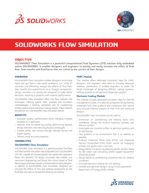
OBJECTIVESOLIDWORKS® Flow Simulation is a powerful Computational Fluid Dynamics (CFD) solution fully embedded within SOLIDWORKS. It enables designers and engineers to quickly and easily simulate the effect of fluid flow, heat transfer and fluid forces that are critical to the success of their designs.OVERVIEWSOLIDWORKS Flow Simulation enables designers to simulate liquid and gas flow in real-world conditions, run “what if” scenarios and efficiently analyze the effects of fluid flow, heat transfer and related forces on or through components. Design variations can quickly be compared to make better decisions, resulting in products with superior performance. SOL IDWORKS Flow Simulation offers two flow modules that encompass industry specific tools, practices and simulation methodologies—a Heating, Ventilation and Air Conditioning (HVAC) module and an Electronic Cooling module. These modules are add-ons to a SOLIDWORKS Flow Simulation license. BENEFITS• Evaluates product performance while changing multiple variables at a rapid pace.• Reduces time-to-market by quickly determining optimal design solutions and reducing physical prototypes.• Enables better cost control through reduced rework and higher quality.• Delivers more accurate proposals.CAPABILITIESSOLIDWORKS Flow SimulationSOLIDWORKS Flow Simulation is a general-purpose fluid flow and heat transfer simulation tool integrated with SOLIDWORKS 3D CAD. Capable of simulating both low-speed and supersonic flows, this powerful 3D design simulation tool enables true concurrent engineering and brings the critical impact of fluid flow analysis and heat transfer into the hands of every designer. In addition to SOL IDWORKS Flow Simulation, designers can simulate the effects of fans and rotating components on the fluid flow and well as component heating and cooling. HVAC ModuleThis module offers dedicated simulation tools for HVAC designers and engineers who need to simulate advanced radiation phenomena. It enables engineers to tackle the tough challenges of designing efficient cooling systems, lighting systems or contaminant dispersion systems. Electronic Cooling ModuleThis module includes dedicated simulation tools for thermal management studies. It is ideal for companies facing thermal challenges with their products and companies that require very accurate thermal analysis of their PCB and enclosure designs.SOLIDWORKS Flow Simulation can be used to:• Dimension air conditioning and heating ducts with confidence, taking into account materials, isolation and thermal comfort.• Investigate and visualize airflow to optimize systems and air distribution.• Test products in an environment that is as realistic as possible.• Produce Predicted Mean Vote (PMV) and Predicted Percent Dissatisfied (PPD) HVAC results for supplying schools and government institutes.• Design better incubators by keeping specific comfort levels for the infant and simulating where support equipment should be placed.• Design better air conditioning installation kits for medical customers.• Simulate electronic cooling for LED lighting.• Validate and optimize designs using a multi-parametric Department of Energy (DOE) method.SOLIDWORKS FLOW SIMULATIONOur 3D EXPERIENCE® platform powers our brand applications, serving 12 industries, and provides a rich portfolio of industry solution experiences.Dassault Syst èmes, t he 3D EXPERIENCE® Company, provides business and people wit h virt ual universes t o imagine sust ainable innovat ions. It s world-leading solutions transform the way products are designed, produced, and supported. Dassault Systèmes’ collaborative solutions foster social innovation, expanding possibilities for the virtual world to improve the real world. The group brings value to over 220,000 customers of all sizes in all industries in more than 140 countries. For more information, visit .Europe/Middle East/Africa Dassault Systèmes10, rue Marcel Dassault CS 4050178946 Vélizy-Villacoublay Cedex France AmericasDassault Systèmes 175 Wyman StreetWaltham, Massachusetts 02451-1223USA Asia-PacificDassault Systèmes K.K.ThinkPark Tower2-1-1 Osaki, Shinagawa-ku,Tokyo 141-6020Japan©2018 D a s s a u l t S y s t èm e s . A l l r i g h t s r e s e r v e d . 3D E X P E R I E N C E ®, t h e C o m p a s s i c o n , t h e 3D S l o g o , C A T I A , S O L I D W O R K S , E N O V I A , D E L M I A , S I M U L I A , G E O V I A , E X A L E A D , 3D V I A , B I O V I A , N E T V I B E S , I F W E a n d 3D E X C I T E a r e c o m m e r c i a l t r a d e m a r k s o r r e g i s t e r e d t r a d e m a r k s o f D a s s a u l t S y s t èm e s , a F r e n c h “s o c i ét é e u r o p ée n n e ” (V e r s a i l l e s C o m m e r c i a l R e g i s t e r # B 322 306 440), o r i t s s u b s i d i a r i e s i n t h e U n i t e d S t a t e s a n d /o r o t h e r c o u n t r i e s . A l l o t h e r t r a d e m a r k s a r e o w n e d b y t h e i r r e s p e c t i v e o w n e r s . U s e o f a n y D a s s a u l t S y s t èm e s o r i t s s u b s i d i a r i e s t r a d e m a r k s i s s u b j e c t t o t h e i r e x p r e s s w r i t t e n a p p r o v a l .• Free, forced and mixed convection• Fluid flows with boundary layers, including wall roughness effects• Laminar and turbulent fluid flows • Laminar only flow• Multi-species fluids and multi-component solids• Fluid flows in models with moving/rotating surfaces and/or parts• Heat conduction in fluid, solid and porous media with/without conjugate heat transfer and/or contact heat resistance between solids• Heat conduction in solids only • Gravitational effectsAdvanced Capabilities• Noise Prediction (Steady State and Transient)• Free Surface• Radiation Heat Transfer Between Solids • Heat sources due to Peltier effect• Radiant flux on surfaces of semi-transparent bodies• Joule heating due to direct electric current in electrically conducting solids• Various types of thermal conductivity in solid medium • Cavitation in incompressible water flows• Equilibrium volume condensation of water from steam and its influence on fluid flow and heat transfer• Relative humidity in gases and mixtures of gases • Two-phase (fluid + particles) flows • Periodic boundary conditions.• Tracer Study• Comfort Parameters • Heat Pipes • Thermal Joints• Two-resistor Components • PCBs•Thermoelectric Coolers• Test the heat exchange on AC and DC power converters.• Simulate internal temperature control to reduce overheating issues.• Better position fans and optimize air flux inside a design.• Predict noise generated by your designed system.Some capabilities above need the HVAC or Electronic Cooling Module.SOLIDWORK Design Support• Fully embedded in SOLIDWORKS 3D CAD• Support SOLIDWORKS configurations and materials • Help Documentation • Knowledge base• Engineering database• eDrawings ® of SOLIDWORKS Simulation results General Fluid Flow Analysis• 2D flow • 3D flow • Symmetry• Sector Periodicity • Internal fluid flows • External fluid flowsAnalysis Types• Steady state and transient fluid flows • Liquids • Gases• Non-Newtonian liquids • Mixed flows• Compressible gas and incompressible fluid flows •Subsonic, transonic and supersonic gas flowsMesher• Global Mesh Automatic and Manual settings • Local mesh refinementGeneral Capabilities• Fluid flows and heat transfer in porous media • Flows of non-Newtonian liquids • Flows of compressible liquids •Real gases。
solidworks flow simulation 要点 -回复
solidworks flow simulation 要点-回复【SolidWorks Flow Simulation要点】SolidWorks Flow Simulation是一种基于计算流体力学(CFD)技术的软件工具,可用于模拟和分析液体和气体流动行为。
它在设计过程中可以提供有关流体流动、传热和压力分布的重要信息,从而帮助工程师优化产品设计并解决与流体相关的问题。
本文将介绍SolidWorks Flow Simulation的一些基本要点,让读者了解如何使用它来进行流体力学仿真和分析。
一、基本概念1.1 计算流体力学(CFD):计算流体力学是一种通过数值方法来模拟和解析流体流动和传热问题的科学和工程领域。
CFD技术可以用于研究各种工程问题,如气流和水流的行为、热传导和对流传热以及流体力学力学等。
1.2 SolidWorks Flow Simulation:SolidWorks Flow Simulation是SolidWorks公司开发的一种CFD软件工具,它可以集成到SolidWorks CAD软件中,为用户提供流体力学仿真和分析功能。
它可以模拟和分析液体和气体在真实环境中的流动行为,并提供有关流速、压力、温度和浓度等参数的详细结果。
二、软件功能2.1 流体域建模:SolidWorks Flow Simulation可以在SolidWorks CAD 环境中创建和编辑流体域模型。
它支持多种复杂流体域的建模,如管道、通道、阀门和风扇等。
用户可以通过绘制几何形状、定义边界条件和材料属性等来进行流体域建模。
2.2 网格生成:在进行流体力学仿真之前,必须对流体域进行网格划分。
SolidWorks Flow Simulation内置了自动网格生成工具,可以根据用户的设置自动生成高质量的网格。
用户可以根据需要调整网格的精度和复杂程度,以获取准确的仿真结果。
2.3 边界条件设置:流体流动仿真需要给定适当的边界条件。
solidworks flow simulation 操作方法
solidworks flow simulation 操作方法摘要:1.SolidWorks Flow Simulation 简介2.操作方法概述3.具体操作步骤3.1 创建模型3.2 设置分析参数3.3 运行模拟3.4 查看结果4.注意事项与优化建议正文:SolidWorks Flow Simulation 是一款专业的流体模拟软件,可以帮助工程师在设计阶段预测流体流动情况,优化产品性能。
本篇文章将为您介绍SolidWorks Flow Simulation 的操作方法。
一、SolidWorks Flow Simulation 简介SolidWorks Flow Simulation 是SolidWorks 公司开发的一款基于计算机流体力学(CFD)的流体模拟软件。
通过该软件,用户可以在设计阶段预测流体流动、热传递等物理现象,从而优化产品性能。
SolidWorks Flow Simulation 具有操作简单、结果精确等优点,广泛应用于工程领域。
二、操作方法概述SolidWorks Flow Simulation 的操作方法分为以下几个步骤:1.创建模型:在SolidWorks 中绘制或导入模型。
2.设置分析参数:定义模拟的物理参数,如流体材料、流速等。
3.运行模拟:启动SolidWorks Flow Simulation 软件,进行模拟计算。
4.查看结果:观察并分析模拟结果,如速度云图、压力分布等。
三、具体操作步骤1.创建模型在SolidWorks 中绘制或导入模型,确保模型尺寸准确,以便进行准确的模拟。
如需导入模型,请将模型文件保存为SolidWorks 可以识别的格式(如.stp、.sldprt 等)。
2.设置分析参数创建一个新的SolidWorks Flow Simulation 文件,并设置以下分析参数:(1)流体材料:选择合适的流体材料,如空气、水等。
(2)流速:设置入口和出口的流速。