对新结构的高频间隙电感的设计和绕组损耗机理的分析
电感、变压器的高频特性与损耗、

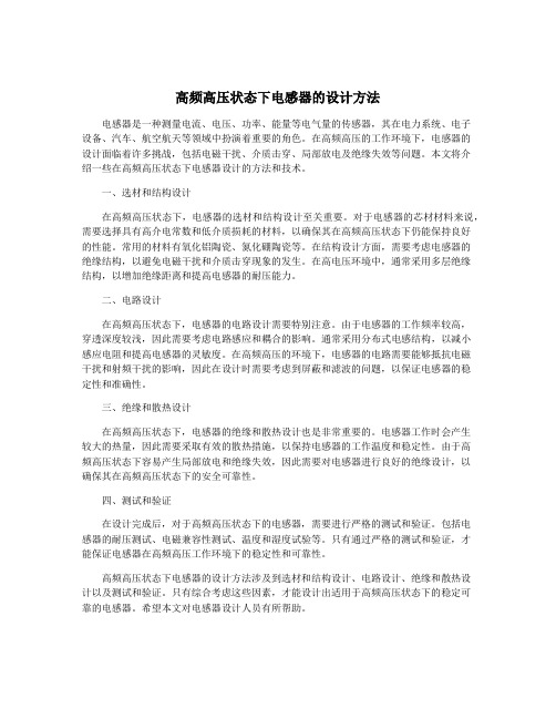
绕组高频效应及其对损耗的影响1.集肤效应1.1集肤效应的原理图1.1表示了集肤效应的产生过程。
图中给出的是载流导体纵向的剖面图,当导体流过电流(如图中箭头方向)时,由右手螺旋法则可知,产生的感应磁动势为逆时针方向,产生进入和离开剖面的磁力线。
如果导体中的电流增加,则由于电磁感应效应,导体中产生如图所示方向的涡流。
由图可知:涡流的方向加大了导体表面的电流,抵消了中心线电流,这样作用的结果是电流向导体表面聚集,故称为集肤效应。
在此引进一个集肤深度〈skin depth〉的概念,此深度的电流密度大小恰好为表面电流密度大小的1/e倍:一般用集肤深度Δ来表示集肤效应,其表达式为:(1.1)其中:γ为导体的电导率,μ为导体的磁导率,f为工作频率。
图1.1.集肤效应产生过程示意图图1.2.高频导体电路密度分布图高频时的导体电流密度分布情形,大致如图1.2所示,由表面向中心处的电流密度逐渐减小。
由上图及式1.1可知,当频率愈高时,临界深度将会愈小,结果造成等效阻值上升。
因此在高频时,电阻大小随着频率而变的情形,就必须加以考虑进去。
1.2影响及应用在高频电路中可以采用空心导线代替实心导线。
此外,为了削弱趋肤效应,在高频电路中也往往使用多股相互绝缘细导线编织成束来代替同样截面积的粗导线,这种多股线束称为辫线。
在工业应用方面,利用趋肤效应可以对金属进行表面淬火。
考虑到交流电的集肤效应,为了有效地利用导体材料和便于散热,发电厂的大电流母线常做成槽形或菱形母线;另外,在高压输配电线路中,利用钢芯铝绞线代替铝绞线,这样既节省了铝导线,又增加了导线的机械强度,这些都是利用了集肤效应这个原理。
集肤效应是在讯号线里最基本的失真作用过程之一,也有可能是最容意被忽略误解的。
与一般讯号线的夸大宣传所言,集肤效应并不会改变所有的高频讯号,并且不会造成任何相关动能的损失。
正好相反,集肤效应会因传导体的不同成分,在传递高频讯号时有不连贯的现象。
高频高压状态下电感器的设计方法

高频高压状态下电感器的设计方法
在高频高压状态下,电感器的设计方法需要考虑以下几个关键因素:频率响应、电流容量、绝缘性能和电感值。
频率响应是指电感器在高频环境下的响应能力。
在设计电感器时,需要选择合适的材料和结构来保证其在高频范围内有较好的信号传递和响应能力。
通常,采用微细绕线和分布电容等技术来解决高频响应问题。
电流容量是指电感器能够承受的最大电流。
在高频高压状态下,电感器往往会受到较大的电流冲击,因此需要选择合适的线径和材料来提高电流容量。
可以采用多层绕线或并联多个电感器的方式来提高整体的电流容量。
绝缘性能是指电感器在高压状态下的绝缘能力。
由于高频高压环境下电压梯度较大,电感器需要具备良好的绝缘性能,以防止电晕放电和击穿事故的发生。
在设计电感器时,可以通过增加绝缘层的厚度和表面涂层的方式来提高其绝缘性能。
电感值是电感器设计中的重要参数。
在高频高压状态下,电感器的电感值可能会发生变化,因此需要通过合理选择材料和结构来降低这种变化。
可以采用空心结构或高品质材料来提高电感器的电感值。
高频高压状态下电感器的设计方法7篇

高频高压状态下电感器的设计方法7篇第1篇示例:高频高压状态下电感器的设计方法概述随着科技的不断发展,高频高压电路在各个领域得到广泛应用,如通信、医疗、工业等。
在这些应用中,电感器作为重要的元器件之一,扮演着转换电类信号与磁性信号之间的重要角色。
在高频高压状态下,传统的电感器设计面临着诸多挑战,因此需要针对高频高压状态下的特殊要求,进行电感器的设计与优化。
本文将重点介绍高频高压状态下电感器的设计方法。
高频高压状态下电感器的特点在高频高压状态下,电感器的特点主要表现在以下几个方面:1. 电感器需要具有较高的耐压能力。
由于高频高压电路中会产生较大的电场和磁场,因此电感器需要具有较高的耐压能力,以避免击穿和漏电等问题。
3. 电感器需要具有较低的损耗。
在高频高压状态下,电感器会受到较大的电磁干扰,因此需要具有较低的损耗,以确保电感器具有较好的稳定性和可靠性。
设计方法1. 选用合适的材料。
在高频高压状态下,电感器需要选用具有较高绝缘强度和较低介电损耗的材料,如氧化锌陶瓷材料、石英等。
这些材料具有较高的绝缘强度和较低的介电损耗,能够满足高频高压状态下的要求。
2. 优化结构设计。
在设计电感器的结构时,需要尽可能减小电感器的损耗和温升。
可以采用多层绕组和分层绝缘的结构设计,以减小电感器的损耗和提高耐压能力。
3. 优化制造工艺。
在制造电感器时,需要采用合适的工艺,确保电感器能够具有较高的绝缘强度和较低的损耗。
可以采用自动化生产线,提高制造效率和产品质量。
4. 严格的测试和验证。
在设计完成后,需要对电感器进行严格的测试和验证,确保其能够满足高频高压状态下的要求。
可以采用高压击穿实验和高温老化实验等测试方法,对电感器进行全面的性能验证。
结论在高频高压状态下,电感器的设计方法需要针对其特殊的工作环境和要求,进行优化和改进。
通过选用合适的材料、优化结构设计、优化制造工艺和严格的测试和验证,可以设计出满足高频高压状态下要求的电感器。
高频开关变压器完成品电感衰减的原因

高频开关变压器完成品电感衰减的原因高频开关变压器是一种常用于高频电路中的电子设备,它通过快速开关操作来实现电能的转换和变压。
然而,在高频开关变压器工作过程中,我们常常会遇到电感衰减的问题。
本文将探讨高频开关变压器电感衰减的原因。
1. 频率效应在高频电路中,电感的电流和电压之间存在相位差,这是由于电感本身的特性所决定的。
在高频开关变压器中,由于频率较高,电感的电流和电压之间的相位差也较大。
这种相位差会导致电感的电压波形和电流波形不同步,从而造成电感的电能损耗和电感值的衰减。
2. 磁芯损耗高频开关变压器中常使用磁芯来提高磁场的传导效率。
然而,磁芯在高频工作条件下会产生磁滞损耗和涡流损耗。
磁滞损耗是指磁芯在磁场变化时,由于磁芯本身的磁导率和磁导特性而产生的能量损耗。
涡流损耗则是指磁场变化时,磁芯中的涡流产生的能量损耗。
这些损耗会导致磁芯的温升,进而影响磁芯的磁导率和电感值,从而引起电感的衰减。
3. 导线损耗高频开关变压器中,导线也会发生电阻损耗。
由于高频电流的特性,导线内部的电阻会导致电流的损耗,从而引起电感的电能损耗和电感值的衰减。
此外,导线的电阻还会产生热量,进一步加剧导线的温升和电感的衰减。
4. 电感元件质量高频开关变压器中使用的电感元件质量也会对电感衰减产生影响。
电感元件的质量直接影响着电感的性能和稳定性。
如果电感元件的制造工艺和材料选择不当,会导致电感元件的内阻增加和电感值的不稳定,从而引起电感的衰减。
为了减少高频开关变压器电感衰减的影响,我们可以采取以下措施:1. 选择合适的磁芯材料和尺寸,减少磁芯损耗;2. 优化导线设计,降低导线的电阻损耗;3. 优化电感元件的制造工艺和材料选择,提高电感元件的质量和稳定性。
总结起来,高频开关变压器电感衰减的原因主要包括频率效应、磁芯损耗、导线损耗和电感元件质量等。
为了减少电感衰减的影响,我们需要选择合适的磁芯材料和尺寸,优化导线设计,以及优化电感元件的制造工艺和材料选择。
MHz级平面变压器的设计及漏感与损耗的分析

MHz级平面变压器的设计及漏感与损耗的分析张杰;刘翠翠;赵运【摘要】基于反激变换器设计一款MHz级平面变压器.首先根据印制板平面变压器磁芯的最小结构常数初选了磁芯,利用磁芯损耗与温升的关系,初步选取了工作磁通密度,进一步计算了原副边匝数、线宽.在磁性元件设计软件Ansoft Pexprt中进一步完成平面变压器结构的设计,在有限元分析软件Maxwell2D中对平面变压器的漏感与损耗进行了仿真.根据仿真设计,对变压器的印制电路板进行了布局,制作实物对漏感损耗进行了测试与计算,验证了平面变压器设计的正确性.【期刊名称】《湖北工业大学学报》【年(卷),期】2018(033)005【总页数】4页(P21-24)【关键词】MHz级;平面变压器;有限元;漏感;损耗【作者】张杰;刘翠翠;赵运【作者单位】湖北工业大学太阳能高效利用湖北省协同创新中心,湖北武汉430068;珠海格力电器股份有限公司,广东珠海519070;国网湖北省电力有限公司沙洋县供电公司,湖北沙洋448200【正文语种】中文【中图分类】TM433高频变压器是开关电源的重要组成部分,传统的高频变压器由于骨架占用了大部分体积,不利于开关电源的高功率密度化,而平面变压器具有造型低、散热性好、漏感小等特点。
但在高频下,平面变压器也会受到高频效应的影响,增加了损耗,降低了电源的效率。
因此,考虑高频效应的影响,减小平面变压器的损耗与漏感,对平面变压器进行优化设计具有重要意义。
1 平面变压器的工程设计以反激平面变压器为例,基于反激变换器的电路参数:输入电压为直流24 V,输出电压为直流5 V,工作频率为1 MHz,最大输出功率为30 W,工作温度为25℃,最大温升不超过40℃。
对平面变压器进行初步设计,主要分为以下步骤。
1.1 初选磁芯根据印制板平面变压器磁芯的最小结构常数可初步选择满足磁芯窗口的磁芯,最小结构常数[1]:(1)其中kh为高度系数,考虑到板层之间的间隙,可取1.1~1.3,此处取1.2。
高频高压状态下电感器的设计方法
高频高压状态下电感器的设计方法电感器是一种测量电流、电压、功率、能量等电气量的传感器,其在电力系统、电子设备、汽车、航空航天等领域中扮演着重要的角色。
在高频高压的工作环境下,电感器的设计面临着许多挑战,包括电磁干扰、介质击穿、局部放电及绝缘失效等问题。
本文将介绍一些在高频高压状态下电感器设计的方法和技术。
一、选材和结构设计在高频高压状态下,电感器的选材和结构设计至关重要。
对于电感器的芯材材料来说,需要选择具有高介电常数和低介质损耗的材料,以确保其在高频高压状态下仍能保持良好的性能。
常用的材料有氧化铝陶瓷、氮化硼陶瓷等。
在结构设计方面,需要考虑电感器的绝缘结构,以避免电磁干扰和介质击穿现象的发生。
在高电压环境中,通常采用多层绝缘结构,以增加绝缘距离和提高电感器的耐压能力。
二、电路设计在高频高压状态下,电感器的电路设计需要特别注意。
由于电感器的工作频率较高,穿透深度较浅,因此需要考虑电路感应和耦合的影响。
通常采用分布式电感结构,以减小感应电阻和提高电感器的灵敏度。
在高频高压的环境下,电感器的电路需要能够抵抗电磁干扰和射频干扰的影响,因此在设计时需要考虑到屏蔽和滤波的问题,以保证电感器的稳定性和准确性。
三、绝缘和散热设计在高频高压状态下,电感器的绝缘和散热设计也是非常重要的。
电感器工作时会产生较大的热量,因此需要采取有效的散热措施,以保持电感器的工作温度和稳定性。
由于高频高压状态下容易产生局部放电和绝缘失效,因此需要对电感器进行良好的绝缘设计,以确保其在高频高压状态下的安全可靠性。
四、测试和验证在设计完成后,对于高频高压状态下的电感器,需要进行严格的测试和验证。
包括电感器的耐压测试、电磁兼容性测试、温度和湿度试验等。
只有通过严格的测试和验证,才能保证电感器在高频高压工作环境下的稳定性和可靠性。
高频高压状态下电感器的设计方法涉及到选材和结构设计、电路设计、绝缘和散热设计以及测试和验证。
只有综合考虑这些因素,才能设计出适用于高频高压状态下的稳定可靠的电感器。
高频电感器线圈损耗

2008.08 ·
99
技术与应用 · TECHNOLOGY
& APPLICATION
的温升。由于现有开发的粉芯磁材料高频损耗特性仍不尽 人意,因此研究高频电感器线圈设计技术和开发新型磁心 结构以减小电感器损耗(线圈损耗)具有重要意义,业界 对此已开展了广泛研究,如通过线圈形状和磁心窗口形状 的设计[1-5],通过引入准分布气隙(Quasi-distributed air- gap)[6,7]、分布气隙(Distributed air-gap)[6,8],或通过气隙的 交错布置 [9]以及采用低磁导率磁材料构造辅助磁路的分布 磁压结构
图2. EI型磁心电感器线圈窗口磁场 Fig.2 Simulation field in winding window of the inductor showed in Fig.1
图3. 简化的EI型磁心电感器线圈窗口磁场 Fig.3 Simplified field in winding window for the inductor showed in Fig.1
TECHNOLOGY & APPLICATION ·
技术与应用
设计磁压以减小高频电感器线圈损耗 技术的研究
毛行奎,陈 为 福州大学电气工程与自动化学院,福建 福州 350002
摘 要: 应用有限元仿真软件深入研究了高频开气隙功率电感器线圈窗口磁场特征及其引起原因,结果表明气隙(磁 压)位置对电感器线圈窗口磁场分布有重要影响,进而严重影响线圈涡流损耗。在此基础上,提出通过设计电 感器磁压以减小其线圈涡流损耗的设计方法。据此设计方法对一些采用标准化以及非标准化磁心的高频功率电 感器线圈涡流损耗进行了分析与设计,并给出设计准则。有限元仿真验证了所提出的设计方法可以有效、很方 便地指导减小高频电感器线圈涡流损耗的研究。 关键词:开关电源;高频功率电感器;线圈损耗;功率变换器
高频高压状态下电感器的设计方法

高频高压状态下电感器的设计方法在高频高压条件下,电感器的设计需要考虑以下几个关键因素:材料的选取、绝缘设计、电磁兼容性、匹配电路以及可靠性和稳定性等。
下面将逐一介绍这些关键因素,并探讨高频高压状态下电感器的设计方法。
1. 材料的选取对于高频高压电感器而言,材料的选取是非常重要的。
传统上,电感器的磁芯材料通常选用氧化铁、镍-锌铁氧体等。
但是在高频高压环境下,这些常规磁芯材料可能会遇到诸多问题,比如磁芯损耗过大、铁损过高、温升等。
在高频高压电感器的设计中,需要选择低损耗、低铁损的特种磁性材料,比如氧化铝陶瓷材料或者氮化硅材料等。
这些材料具有较好的高频特性和较低的损耗,能够在高频高压环境下保持较好的性能。
2. 绝缘设计在高频高压条件下,绝缘设计是非常关键的。
由于高频高压下会产生较大的电磁场和电压梯度,因此电感器的绝缘要求较高。
一般来说,高频高压电感器的绝缘设计需要考虑以下几个方面:电磁屏蔽、介质强度、电磁兼容性等。
采用合适的绝缘材料和结构设计,可以有效地降低电感器的绝缘电阻、电容和电感等参数,确保电感器在高频高压环境下的稳定性和可靠性。
3. 电磁兼容性4. 匹配电路在高频高压电感器的设计中,匹配电路也是非常重要的。
由于高频高压条件下电感器的特性会发生变化,因此需要设计合适的匹配电路,使电感器能够有效地与外部电路相匹配,从而确保信号传输的稳定性和可靠性。
合理设计匹配电路可以有效地降低电感器的阻抗变化,提高信号的传输效率。
5. 可靠性和稳定性高频高压电感器的设计需要充分考虑其可靠性和稳定性。
在高频高压条件下,由于电磁场的干扰、温升等因素,电感器容易受到一些外部因素的影响,因此需要设计具有良好抗干扰能力和稳定性的电感器。
可以通过选用合适的材料、优化结构设计、精心匹配电路等方式,提高电感器的可靠性和稳定性。
- 1、下载文档前请自行甄别文档内容的完整性,平台不提供额外的编辑、内容补充、找答案等附加服务。
- 2、"仅部分预览"的文档,不可在线预览部分如存在完整性等问题,可反馈申请退款(可完整预览的文档不适用该条件!)。
- 3、如文档侵犯您的权益,请联系客服反馈,我们会尽快为您处理(人工客服工作时间:9:00-18:30)。
4036IEEE TRANSACTIONS ON MAGNETICS,VOL.41,NO.10,OCTOBER2005 Winding Loss Mechanism Analysis and Design for New Structure High-Frequency Gapped InductorXingkui Mao1,Wei Chen1;2,and Yunxiu Li2College of Electrical Engineering and Automation,Fuzhou University,Fujian Province,350002,China Research and Development Center,Delta Electronics(Shanghai)Company Ltd.,Pudong,Shanghai,201209,China Winding eddy current loss mechanism of high-frequency gapped inductor is studied deeply by two-dimensionalfinite element analysis. It reveals that concentrated distribution of the magneticfield in the winding window due to the air gap obviously leads to higherflux strength and then higher winding eddy current loss.Based on the analysis,a new simple inductor structure is proposed to make thefield in the winding window more uniform by introducing a low permeability magnetic shunt between the gapped core leg and the winding, resulting in a significant winding loss reduction.Moreover,field analysis and design for the new structure are also performed.Index Terms—Eddy current loss,inductors,magnetic devices,power conversion,winding.I.I NTRODUCTIONI NDUCTORS have enormous applications in high-frequencyswitch-mode power supply for energy storage andfiltering. For inductors,all magneto-motive force(MMF)produced by exciting current must be supported in magnetic core or air gaps. Low permeability(permeability)cores have benefits of lower winding loss because no air gap is needed and the magnetic field in the winding window is more uniform.Unfortunately, low permeability cores,whether they are iron powder,high-flux,Kool-mu,or molypermalloy powder(MPP),exhibit much higher core loss than that of the ferrite cores in large alternating current(ac)flux density and high frequency applications,such as resonant inductors and power-factor correction(PFC)induc-tors working in discontinuous construction mode(DCM).So high permeability ferrite cores gapped with air gap are usually adopted in such applications for reducing core loss.But an in-ductor constructed with high permeability ferrite gapped core used in high-frequency switch-mode power supply will lead to high extra winding eddy current loss due to the introduction of air gap,resulting in low efficiency and high temperature rise in the inductor.In order to reduce this extra winding loss,many techniques were proposed,including winding shape design[1], core dimension consideration[2],segmenting single air gap[3], staggering air gap arrangement[4],and distributing air gap by combination of high permeability and low permeability mag-netic core[5].But all these techniques make the winding and core structures much more complex.In this work,by two-dimensional(2-D)eddy currentfinite element analysis(FEA),winding eddy current loss mechanism in the inductor constructed with ferrite core and air gap is deeply investigated and then a new very simple inductor structure is proposed to reduce the winding loss greatly.Moreover,analysis and design for the new structure are also performed.Digital Object Identifier10.1109/TMAG.2005.854991Fig.1.Magneticfield of gapped inductor by2-D FEA(halfcore).Fig.2.Simplified magneticfield of gapped inductor(half core).II.W INDING L OSS M ECHANISM A NALYSIS FORH IGH-F REQUENCY G APPED I NDUCTORFlux distribution of an inductor constructed with high per-meability ferrite core and air gap in central core leg workingat frequency300kHz is shown in Fig.1byfield simulation.It can be seen that thefluxes can be classified into three por-tions:mainfluxes which pass through high permeability mag-netic core and air gap,fringingfluxes which diffuse into thewinding window near the air gap,and bypassfluxes which passacross the winding window between the two adjacent legs,as inFig.2.Among thesefluxes,mainfluxes corresponding to mostof the stored magnetic energy of the inductor do not penetrateinto winding conductors and induce no extra winding loss.But 0018-9464/$20.00©2005IEEEMAO et al.:WINDING LOSS MECHANISM ANALYSIS AND DESIGN4037Fig.3.New structure inductor proposed (half core).the other two-portion fluxes will induce high eddy current loss at high frequency because they cut into winding window.In mech-anism investigation on the winding eddy current loss,the effects by these two-portion fluxes are focused for study.It is well known that magnetic fluxes are caused by MMF applying across magnetic path.In an inductor gapped with air gap,almost all MMF or ampere-turn product (NI)should drop across the air gap.So,the fringing fluxes near air gap are caused by MMF produced by all inductor current.But bypass fluxes are caused by MMF applying across between the two adjacent core legs.This MMF producing bypass fluxes increases with in-crement of winding ampere-turnproductand drop across air gap along winding window height,so staggering air gap ar-rangement is helpful in reducing the winding loss [3].It is just the concentrations of the two MMF due to the air gap result in the concentrations of the magnetic fluxes,including fringing and bypass fluxes,in the winding window and then much higher winding eddy current loss at high frequency.So finding some new and simple structure to distribute the two MMF and make magnetic field more uniform in winding window will reduce the winding loss.III.N EW S TRUCTURE TO D ISTRIBUTE M MF FORH IGH -F REQUENCY G APPED I NDUCTORThe new structure proposed is shown in Fig.3.A thin thick-ness and low permeability magneticmaterial is introduced into between the gapped core leg and the winding to form two parallel magneticpathsand for all fluxes to pass through.With this structure,MMF producing by all current is dis-tributed along magneticpathconsisting of air gap Acf1,Acf2,and low permeability magnetic material ,while the MMF is concentrated along magneticpath consisting of high permeability magnetic core and airgap .So,magnetic filed in winding window will become more uniform by the introduction ofpath ,resulting in great winding loss reduction.Moreover,path supports the main fluxes or most of the magnetic energy,whilepathjust acts as a magnetic shunt to support a very small portion of the fluxes,including fringing fluxes and bypass fluxes.So,a very small extra core loss is introduced in magnetic path .Low permeability magneticmaterial can be available by flexible ferrite polymer composites (FPC)provided by EPCOS or other vendors and then the new structure can be very easilyconstructed.Fig.4.Example inductor of the new structure under studying (halfcore).Fig.5.Normalized winding loss of new structure versus of the material F and length d of air gap Acf1,Acf2at frequency 300kHz.Fig.6.Magnetic field strength along the surface of the most left winding layer (line A-A)at =20for the material,length d =5mm for air gap Acf1,Acf2,and frequency 300kHz.IV .A NALYSIS AND D ESIGN FOR THE N EW S TRUCTURE In order to achieve the more uniform magnetic field in the winding window and minimize the winding loss,factors af-fecting the MMF along magneticpath or the design parame-ters,such as permeability value and size of the magnetic mate-rial need to be analyzed and properly designed.An example inductor,as in Fig.4,is used to study the new structure by Ansoft 2-D FEA.The simulation results in Fig.5show the normalized winding loss versusrelativeand the size of the magneticmaterial at frequency 300kHz.Thelength of air gap Acf1and Acf2indicate the size here.In Fig.5,the normalized winding loss is with respect to thesewithout the magnetic material .Withof the material ,the minimum normalized winding loss are only 0.41atlengthmm,and the magnetic field strength in winding window is shown in Fig.6,showing more uniform magnetic field of the new structure compared with that of the structure without ma-terial .Although winding loss reaches its minimumat mmand from Fig.5,here is set to be 5mm because4038IEEE TRANSACTIONS ON MAGNETICS,VOL.41,NO.10,OCTOBER2005Fig.7.Winding loss versus distance a at =20for the material F ,length d =5mm for air gap Acf1,Acf2and frequency 300kHz.Fig.8.Winding loss versus relative permeability of the material F at length d =5mm for air gap Acf1,Acf2,and frequency 300kHz.value of flexible FPC now available is equal or less than 20andwith,the loss is minimumwith mm.So,mm is de fined in the following analysis.Inaddition,can not be zero,because some space is also needed for winding bobbin.Moreover,the MMF distribution along magneticpathis affected greatly bypath because thatdistance between the two magnetic paths is fairly small.Keeping distance between the gapped core leg and the winding constant,we get Fig.7byvarying .Fig.7shows thatsmaller will lead to less lossreduction.Especiallyduringmm,loss is even higher than that of single air gap.It is because the magneticmaterial will tend to bring more air-gap fringing fluxes to the winding conductorswhen is too small.It must be noted that the low permeability magneticmaterial can not be regarded as a magnetic shielding to prevent the air gap fringing fluxes from going into winding window [6].If function of thematerial is wrongly regarded as shielding,the higher permeability of thematerial should lead to better shielding effect and then lower winding loss.But from Fig.8,ifis too high,thematerial will lose its function to reduce the winding loss.It is because althoughhighercan reduce the field strength near airgap ,it will bring much higher field strength near the air gap Acf1and Acf2.Fig.9of magnetic fieldwithof thematerialand mm clearly shows the phenomena.So,in the new structure design,we can first setdistance equal to thickness of winding bobbin,then select fairlyhigher for thematerial to get minimum loss byvarying .How-ever,even though the winding loss reach their minimum valueat,as in Fig.8,the tradeoff between the winding loss reduction and the saturation of the magneticmaterial should also be considered in the design,because higherpermeabilityFig.9.Magnetic field strength along line A-A at =1500for the material F ,length d =5mm for air gap Acf1,Acf2,and frequency 300kHz.material is likely to attract more fluxes and become saturated.The design for avoiding saturation of the low permeability ma-terial can be achieved by considerationsof value and size of the material ordistance between gapped core leg and the material by 2-D eddy current filed simulation.For example,if flux density of thematerial is beyond the saturation value,one should modify the design with lower permeability and more thickness of the material or larger length d.V .C ONCLUSIONInvestigations on the winding eddy current loss mechanism reveal that the fringing fluxes and bypass fluxes are caused by the concentrated MMF distribution due to the air gap in gapped inductor.In the proposed new structure,low permeability mag-netic material introduced into between the gapped core leg and the winding builds an auxiliary magnetic path to make the MMF distribution more uniform in the winding window,resulting in great winding eddy current loss reduction of the high-frequency gapped inductor.With the new structure inductor,the parameter of the auxiliary magnetic path should be carefully designed to achieve the minimum winding loss.The effect of the new struc-ture inductor has been veri fied by 2-D FEA simulation.A CKNOWLEDGMENTThis work was supported in part by the Natural Science Foun-dation of Fujian Province,China under Grant A0210011and in part by the Science Research Foundation of Fuzhou University under Grant 2004-XY-02.R EFERENCES[1]J.Hu and C.R.Sulliivan,“Optimization of shapes for round-wire high-frequency gapped-inductor windings,”IEEE IAS ,pp.907–912,1998.[2]R.A.Jensen and C.R.Sullivan,“Optimal core dimensional ratios forminimizing winding loss in high-frequency gapped-Inductor windings,”IEEE APEC ,pp.1164–1169,2003.[3]W.Chen,J.He,and L.Henglian,“Winding loss analysis and new air-gaparrangement for high frequency inductors,”IEEE PESC ,pp.2084–2089,2001.[4]J.Hu and C.R.Sullivan,“AC resistance of planar power inductorsand the quasidistributed gap technique,”IEEE Trans.Power Electr.,pp.558–567,2001.[5]N.H.Kutkut and M.D.Divan,“Optimal air-gap design in high-fre-quency foil windings,”IEEE Trans.Power Electr.,pp.942–949,1998.[6]P.Wallmeier and H.Grotstollen,“Magnetic shielding applied to high-frequency inductors,”IEEE IAS ,pp.1131–1138,1997.Manuscript received January 27,2005.。