ASTM钢铁标准.A956
钢材知识ASTMA钢材标准AA
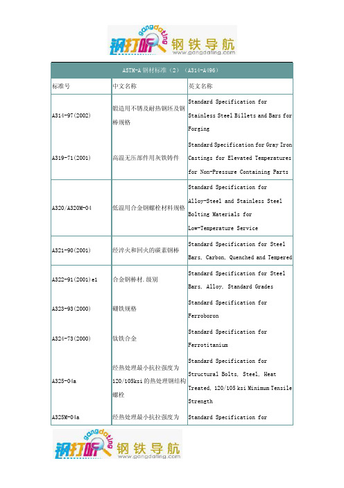
Standard Specification for Seamless 低温设备用无缝与焊接碳素
and Welded Carbon and Alloy-Steel 和合金钢管
Tubes for Low-Temperature Service
Standard Specification for Seamless 高温用无缝铁素体合金钢管 Ferritic Alloy-Steel Pipe for
830Mpa 的热处理钢结构螺栓 Structural Bolts, Steel, Heat Treated 830 Mpa Minimum Tensile Strength [Metric]
铸铁冲击试验方法
Standard Test Methods for Impact Testing of Cast Irons
A356/A356M-98(2003)
合金钢和不锈钢铸件
Stainless Steel, Heavy-Walled for
Steam Turbines
A358/A358M-04
Standard Specification for
Electric-Fusion-Welded Austenitic 高温用电熔焊奥氏体铬镍合
用瓦特计--安培计--伏特计 Standard Test Method for Alternating
法(100-10000 赫兹)和 25 厘 Current Magnetic Properties of
米艾普斯亭框测定材料的交 Materials Using the
流磁性能的试验方法
Wattmeter-Ammeter-Voltmeter
ASTM A标准(中文)

AA1000-99 弹簧专用碳钢和合金钢钢丝规范A1001-99 大型材高强度钢铸件规范A1002-99 镍铝类合金铸件规范A100-93(2000) 硅铁A101-93(2000) 铬铁A102-93(2000) 钒铁合金A105/A105M-01 管系部件用碳素钢锻件A106-999e1 高温用无缝碳素钢管A108-99 优质冷加工碳素钢棒材技术规范A109/A109M-00e1 冷轧碳素钢带技术规范A111-99a 电话和电报线路用镀锌"铁"丝规格A116-00 镀锌钢丝编织栏栅网A121-99 镀锌刺钢丝A123/A123M-00 钢铁产品的锌镀层(热浸镀锌)技术规范A125-96 热处理螺旋形钢弹簧A126-95(2001) 阀门、法兰和管配件用灰铁铸件A128/A128M-93(1998) 钢铸件,奥氏体锰A131/A131M-94 海船用结构钢A132-89(2000) 钼铁合金A134-96 电熔(电弧)焊钢管(NPS为16英寸和16英寸以上)A135-01 电阻焊钢管A139-00 电熔(电弧)焊钢管(4英寸以上的)A143-74(1999) 热浸镀锌结构钢制品防脆裂措施和探测脆裂的程序A146-64(2000) 氧化钼制品A148/A148M-01 结构用高强度钢铸件A153/A153M-00 钢铁制金属构件上镀锌层(热浸)A159-83(2001) 汽车用灰铁铸件A167-99 不锈钢和耐热铬镍钢板、薄板及带材A176-99 不锈钢和耐热铬钢板、薄板及带材A178/A178M-95(2000) 电阻焊接碳素钢钢管及碳锰钢锅炉和过热器管的技术规范A179/A179M-90a(1996)e1 热交换器和冷凝器用无缝冷拉低碳钢管A181/A181M-01 普通锻制碳素钢管的规格A182/A182M-01 高温设备用锻制或轧制的合金钢管法兰、锻制管件、阀门及零件A183-98 钢轨用碳素钢螺栓和螺母A184/A184M-01 混凝土加筋用变形钢筋编织网A185-97 钢筋混凝土用焊接钢丝结构A1-00 碳素钢丁字轨A192/A192M-91(1996)e1 高压用无缝碳素钢锅炉管A193/A193M-01 高温设备用合金钢和不锈钢螺栓材料A194/A194M-01 高温和高压设备用碳素钢与合金钢螺栓和螺母的规格A197/A197M-00 化铁炉用可锻铸铁A20/A20M-01 压力容器用钢板材通用要求A202/A202M-93(1999) 压力容器用铬锰硅合金钢板A203/A203M-97 压力容器用镍合金钢板A204/A204M-93(1999) 压力容器用钼合金钢板A209/A209M-98 锅炉和过热器用无缝碳钼合金钢管A210/A210M-96 锅炉和过热器用无缝中碳素管A213/A213M-01 无缝铁素体和奥氏体合金钢锅炉、过热器和换热器管A214/A214M-96 热交换器与冷凝器用电阻焊接碳素钢管A216/A216M-93(1998) 高温下使用的适合于熔焊的碳素钢铸件规格A217/A217M-01 适合高温受压零件用合金钢和马氏体不锈钢铸件A21-94(1999) 铁路用未经热处理和经热处理的碳素钢轴A220/A220M-99 珠光体可锻铁A225/A225M-93(1999) 压力容器用锰矾镍合金钢板A227/A227M-99 机械弹簧用冷拉钢丝A228/A228M-00 乐器用优质弹簧钢丝A229/A229M-99 机械弹簧用油回火的钢丝A230/A230M-99 阀门用油回火优质碳素钢弹簧丝A231/A231M-96 铬钒合金钢弹簧丝A232/A232M-99 阀门用优质铬钒合金钢弹簧丝A234/A234M-00a 中温与高温下使用的锻制碳素钢及合金钢管配件A239-95(1999) 用普力斯试验法(硫酸铜浸蚀)确定铁或钢制品上镀锌层最薄点的测试方法A240/A240M-01 压力容器用耐热铬及铬镍不锈钢板、薄板及带材A242/A242M-00a 高强度低合金结构钢A247-67(1998) 铁铸件中石墨显微结构评定试验方法A249/A249M-01 锅炉、过热器、换热器和冷凝器用焊接奥氏体钢管A250/A250M-95(2001) 锅炉和过热器用电阻焊铁素体合金钢管A252-98e1 焊接钢和无缝钢管桩A254-97 铜焊钢管规格A255-99 测定钢淬透性用末端淬火试验的标准试验方法A262-98 奥氏体不锈钢晶间浸蚀敏感性的检测A263-94a(1999) 耐腐蚀铬钢包覆板材,薄板材及带材技术规范A264-94a(1999) 包覆的不锈铬镍钢板,薄板及带材规格A265-94a(1999) 镍和镍基合金包覆钢板规格A266/A266M-99 压力容器部件用碳素钢锻件规格A268/A268M-01 一般设备用无缝和焊接铁素体与马氏体不锈钢管A269-01 一般设备用无缝和焊接奥氏体不锈钢管A27/A27M-95(2000) 通用碳素钢铸件A270-01 卫生设施用无缝钢和焊接奥氏体不锈钢管A275/A275M-98 钢锻件的磁粉检查试验方法A276-00a 不锈钢棒材和型材A278-93 适用于650F容压部件用灰铸铁件的技术规范A283/A283M-00 低和中等抗拉强度碳素钢板A285/A285M-90(2001) 压力容器用低和中等抗拉强度的碳素钢板A288-91(1998) 涡轮发电机磁性定位环用碳素钢和合金钢锻件A289/A289M-97 发电机非磁性定位环用合金钢锻件的技术规范A29/A29M-99e1 热锻及冷加工碳素钢和合金钢棒A2-90(1997) 普通型,带槽和防护型碳素工字钢轨A290-95(1999) 减速器环用碳素钢和合金钢锻件A291-95(1999) 减速器小齿轮、齿轮和心轴用碳素钢和合金钢锻件A295-98 高碳耐磨轴承钢技术规范A297/A297M-97(1998) 一般用耐热铬铁与镍铬铁合金钢铸件规格A299/A299M-97e1 压力容器用锰硅碳钢板A302/A302M-97e1 压力容器用锰钼和锰钼镍合金钢板A304-96 有末端淬火淬透性要求的合金钢棒材的技术规范A307-00 抗拉强度为60000psi的碳素钢螺栓和螺柱的技术规范A308-99 经热浸处理镀有铅锡合金的薄板材的技术规范A309-94a(1999) 用三点试验法测定长镀锌薄钢板镀层的重量成分的试验方法A311/A311M-95(2000) 有机械性能要求的消除应力的冷拉碳素钢棒A312/A312M-00c 无缝和焊接奥氏体不锈钢管A313/A313M-98 不锈钢弹簧丝技术规范A314-97 锻造用不锈及耐热钢坯及钢棒规格A31-00 钢铆钉及铆钉和压力容器用棒材A319-71(2001) 高温无压部件用灰铁铸件A320/A320M-01 低温用合金钢螺栓材料规格A321-90(1995)e1 经淬火和回火的碳素钢棒A322-91(1996) 合金钢棒材.级别A323-93(2000) 硼铁规格A324-73(2000) 钛铁合金A325-00 经热处理最小抗拉强度为120/105ksi的钢结构螺栓A325M-00 结构钢连接件用高强度螺栓(米制)A327-91(1997) 铸铁冲击试验方法A327M-91(1997) 铸铁冲击试验方法(米制)A328/A328M-00 薄钢板桩A331-95(2000) 冷加工合金钢棒A333/A333M-99 低温用无缝与焊接钢管规格A334/A334M-99 低温设备用无缝与焊接碳素和合金钢管A335/A335M-01 高温用无缝铁素体合金钢管A336/A336M-99e1 压力与高温部件用合金钢锻件规格A338-84(1998) 铁路,船舶和其他重型装备在温度达到650华氏度(345摄氏度)时使用的可锻铸铁法兰,管件和阀门零件A34/A34M-96 磁性材料的抽样和采购试验的标准惯例A340-99a 有关磁性试验用符号和定义的术语A341/A341M-00 用直流磁导计和冲击试验法测定材料的直流磁性能的试验方法A342/A342M-99 磁铁材料导磁率的试验方法A343-97 在电力频率下用瓦特计-安培计-伏特计法(100-1000赫兹)和25 厘米艾普斯亭(EPSTEIN) 机架测定材料的交流电磁性能的试验方法A345-98 磁设备用平轧电炉钢A348/A348M-00 用瓦特计--安培计--伏特计法(100-10000赫兹)和25厘米艾普斯亭框测定材料的交流磁性能的试验方法A350/A350M-00c 要求进行缺口韧性试验的管道部件用碳素钢与低合金钢锻件技术规范A351/A351M-00 容压零件用奥氏体及奥氏体铁素体铸铁的技术规范A352/A352M-93(1998) 低温受压零件用铁素体和马氏体钢铸件规格A353/A353M-93(1999) 压力容器用经二次正火及回火处理的含9%镍的合金钢板A354-01 淬火与回火合金钢螺栓,双头螺栓及其他外螺纹紧固件规格A355-89(2000) 渗氮用合金钢棒A356/A356M-98e1 蒸汽轮机用厚壁碳素钢、低合金钢和不锈钢铸件A358/A358M-01 高温用电熔焊奥氏体铬镍合金钢管A36/A36M-00a 碳素结构钢技术规范A363-98 地面架空线用镀锌钢丝绳A367-60(1999) 铸铁的激冷试验方法A368-95a(2000) 不锈钢和耐热钢丝绳的标准A369/A369M-01 高温用锻制和镗孔碳素钢管和铁素体合金钢管A370-97a 钢制品机械测试的标准试验方法和定义A372/A372M-99 薄壁压力容器用碳素钢及合金钢锻件A376/A376M-01 高温中心站用无缝奥氏钢管A377-99 球墨铸铁压力管规范索引A380-99e1 不锈钢零件、设备和系统的清洗和除垢A381-96 高压输送用金属弧焊钢管A384-76(1996) 防止钢组件热浸镀锌时翘曲和扭曲用安全保护A385-00 提供高质量镀锌覆层(热浸)A3-01 低、中、高碳素钢鱼尾(连接)板A387/A387M-99e1 压力容器用铬钼合金钢板A388/A388M-95(2000)e1 重型钢锻件超声波检测A389/A389M-93(1998) 适合高温受压部件用经特殊热处理的合金钢铸件规格A390-95(2001) 饲养家禽用镀锌钢丝栏栅网(六角形和直线形)A391/A391M-98 80号合金钢链条A392-96 镀锌钢丝链环栏栅网A394-00 传动塔架用镀锌和裸露钢螺栓A395/A395M-99 高温用铁素体球墨铸铁受压铸件A400-69(2000) 钢棒的成分及机械性能选择指南A401/A401M-98 铬硅合金钢丝A403/A403M-00b 锻制奥氏体不锈钢管配件A407-93(1998) 盘簧用冷拉钢丝A409/A409M-01 腐蚀场所或高温下使用的焊接大口径奥氏体钢管A411-98 镀锌低碳钢铠装线A413/A413M-00 碳素钢链A414/A414M-00 压力容器用碳素薄钢板A416/A416M-99 预应力混凝土用无涂层七股钢铰线A417-93(1998) 之字型、方型和正弦型装垫弹簧元件用冷拉钢丝A418-99 涡轮机及发电机钢转子锻件的超声波检查方法A420/A420M-00b 低温下用锻制碳素钢和合金钢管配件A421/A421M-98a 预应力混凝土用无涂层消除应力钢丝的技术规范A423/A423M-95(2000) 无缝和电焊低合金钢管A424-00 搪瓷用钢薄板A426-92(1997) 高温用离心铸造的铁素体合金钢管A427-74(1996)e1 冷轧和热轧用锻制合金钢辊A428/A428M-01 钢铁制品上铝覆层重量的测试方法A434-90a(2000) 热轧与冷精轧经回火及淬火的合金钢棒A435/A435M-90(2001) 钢板的直射束纵向超声波检验A436-84(1997)e1 奥氏体灰口铁铸件A437/A437M-01 高温用经特殊处理的涡轮型合金钢螺栓材料A438-80(1997) 灰铸铁横向弯曲试验A439-83(1999) 奥氏体可锻铸铁铸件A447/A447M-93(1998) 高温用镍铬铁合金钢铸件(25-12级)A449-00 经淬火和回火的钢螺栓和螺柱A450/A450M-96a 碳素钢管、铁素体合金钢管及奥氏体合金钢管A451-93(1997) 高温用离心铸造的奥氏体钢管A453/A453M-00 具有同奥氏体钢相类似的膨胀系数、屈服强度为50-120Ksi(345-827MPa)的耐高温螺栓材料A455/A455M-90(2001) 压力容器用高强度碳锰钢板A456/A456M-99 大型曲轴锻件的磁粉检查A459-97 镀锌平轧扁钢铠装带A460-94(1999) 包铜钢丝绳标准A463/A463M-00 热浸镀铝薄钢板A466/A466M-98 非焊接碳素钢链A467/A467M-98 机器链和盘旋链A469-94a(1999) 用于发电机转子的真空处理钢锻件A470-01 涡轮机转子和轴用经真空处理的碳素钢和合金锻件A471-94(1999) 涡轮转子转盘和转轮用真空处理合金钢锻件技术规范A472-98 蒸汽涡轮机轴及转子锻件的热稳定性的试验方法A473-01 不锈和耐热钢锻件A474-98 包铝钢丝绳标准A475-98 镀锌钢丝绳A476/A476M-00 造纸厂干燥辊用球墨可锻铸铁件A478-97 铬镍不锈钢和耐热钢制编织钢丝A479/A479M-00 锅炉及压力容器用不锈钢和耐热钢棒与型材A47/A47M-99 铁素体可锻铁铸件A480/A480M-01 扁平轧制耐热不锈钢厚板材、薄板材和带材通用要求A481-94(2000) 金属铬A482-93(2000) 铬铁硅A483-64(2000) 硅锰合金A484/A484M-00 不锈及耐热锻钢棒,钢坯及锻件的规格A485-00 高淬透性耐磨轴承钢的技术规范A487/A487M-93(1998) 受压钢铸件A488/A488M-01 钢铸件焊接规程和工作人员的合格鉴定A48-94ae1 灰铁铸件A489-00 碳素钢吊耳A490-00 最小拉伸强度为150千磅/平方英寸热处理钢结构螺栓A491-96 镀铝钢链环栏栅结构A492-95(2000) 耐热不锈钢丝绳A493-95(2000) 冷镦和冷锻不锈钢和耐热钢丝A494/A494M-00 镍和镍合金铸件A495-94(2000) 硅钙合金钢技术规范A496-97ae1 钢筋混凝土用变形钢丝A497-99e1 钢筋混凝土用焊接变形钢丝网A498-98 无缝与焊接碳素钢,铁素体钢与奥氏体钢制有整体散热片的换热器钢管A49-01 经热处理的碳素钢鱼尾(连接)板,微合金鱼尾板及锻制碳素钢异型鱼尾板A499-89(1997)e1 轧制丁字钢轨用的碳素钢棒材及型材的技术规范A500-01 圆形与异型焊接与无缝碳素钢结构管A501-01 热成型焊接与无缝碳素钢结构管A503/A503M-01 锻制大型曲轴的超声波检验A504-93(1999) 锻制碳素钢轮A505-00 热轧和冷轧合金钢薄板和带材A506-00 正规质量及优质结构的热轧和冷轧合金钢薄板与带材A507-00 优质拉拔,热轧和冷轧合金钢薄板与带材A508/A508M-95(1999) 压力容器用经回火和淬火真空处理的碳素钢与合金钢锻件A510-00 碳素钢盘条和粗圆钢丝通用要求A510M-00 碳素钢盘条和粗圆钢丝(米制)A511-96 无缝不锈钢机械管A512-96 冷拉对缝焊碳素钢机械管A513-00 电阻焊碳素钢与合金钢机械钢管A514/A514M-00a 焊接用经回火与淬火的高屈服强度合金钢板A515/A515M-92(1997) 中温及高温压力容器用碳素钢板A516/A516M-90(2001) 中温及低温压力容器用碳素钢板A517/A517M-93(1999) 压力容器用经回火与淬火的高强度合金钢板A518/A518M-99 耐蚀高硅铁铸件A519-96 无缝碳素钢与合金钢机械管A521-96 一般工业用闭式模钢锻件A522/A522M-95b(2000) 低温用锻制或轧制含镍8%和9%的合金钢法兰,配件,阀门和零件规格A523-96 高压管型电缆线路用平端无缝与电阻焊钢管A524-96 常温和低温用无缝碳素钢管A529/A529M-00 高强度碳锰结构钢质量A530/A530M-99e1 特种碳素钢和合金钢管A531/A531M-91(1996) 涡轮发电机钢定位环的超声波检验A532/A532M-93a(1999)e1 耐磨铸铁A533/A533M-93(1999) 压力容器用经回火和淬火的锰钼及锰钼镍合金钢板A534-94 用于耐摩擦轴承的渗碳钢A536-84(1999)e1 球墨铸铁件A537/A537M-95(2000) 压力容器用经热处理的碳锰硅钢板A53/A53M-01 无镀层热浸的、镀锌的、焊接的及无缝钢管的技术规范A539-99 天然气和燃料油管线用电阻焊钢盘管A540/A540M-00 特殊用途的合金钢螺栓材料A541/A541M-95(1999) 压力容器部件用经淬火和回火的碳素钢及合金钢锻件A542/A542M-99e1 压力容器用经回火和淬火的铬钼、铬钼钒及铬钼钒钛硼合金钢板A543/A543M-93(1999) 压力容器用经回火和淬火的镍铬钼合金钢板A550-78(2000) 铌铁合金A551-94(1999) 钢轮箍A553/A553M-95(2000) 压力容器用经回火和淬火的含8%及9%镍的合金钢板A554-98e1 焊接的无缝钢机械管A555/A555M-97 耐热不锈钢丝和盘条的通用要求A556/A556M-96 无缝冷拉碳素钢给水加热器管A560/A560M-93(1998) 铬镍合金铸件A561-71(1999) 工具钢棒的宏观刻蚀试验A562/A562M-90(2001) 搪玻璃或扩散金属镀层的压力容器用锰钛合金碳素钢板A563-00 碳合金钢螺母A563M-00 碳素钢及合金钢螺母技术规范(米制)A564/A564M-01 热轧及冷精轧时效硬化处理过的不锈钢棒材和型材技术规范A565-97 高温用马氏体不锈钢棒,锻件和锻制坯规格A568/A568M-00b 热轧及冷轧高强度低合金碳素钢薄板A571-84(1997) 适用于低温压力容器零件的奥氏体球墨铸铁件A571M-84(1997) 适用于低温压力容器零件的奥氏体球墨铸铁件(米制)A572/A572M-00a 高强度低合金钴钒结构钢技术规范A573/A573M-00a 增强韧性的结构碳素钢板A574-00 合金钢内六角螺钉A574M-00 合金钢内六角螺钉(米制)A575-96 商品级碳素钢棒(M级)A576-90b(2000) 特级热轧碳素钢棒A577/A577M-90(2001) 钢板的超声角波束检验A578/A578M-96(2001) 特殊设备用的普通钢板和包覆钢板的直波束超声探伤检验A579-99 超高强度合金钢锻件A580/A580M-98 耐热不锈钢丝A581/A581M-95b(2000) 高速切削用耐热不锈钢丝和盘条A582/A582M-95b(2000) 热轧或冷精轧的高速切削不锈及耐热钢棒A583-93(1999) 铁路用铸钢轮A584-97 镀铝钢丝编织栅栏网A585-97 镀铝刺钢丝A586-98 镀锌平行和螺旋形钢丝绳A587-96 化学工业用电阻焊低碳钢管A588/A588M-00a 高强度低合金结构钢4英寸(100mm)厚屈服点最小为50ksi(345MPa) A589-96 水井用无缝和焊接碳素钢管A591/A591M-98 薄镀层电解镀锌薄钢板A592/A592M-89(1999) 压力容器用经回火和淬火的高强度低合金钢锻制附件和零件A595-98 结构用圆锥形低碳钢管A596/A596M-95(1999) 用环形试验法和冲击法测定材料的直流磁性能的试验方法A597-87(1999) 铸造工具钢A598-92(1997) 磁放大器磁芯的磁性能测试法A599/A599M-99 锡制品,电解镀锡的冷滚轧薄板规范A6/A6M-01 轧制结构钢板材、型材和薄板桩通用技术要求A600-92a(1999) 高速工具钢A601-96(2000) 电解金属锰A602-94(1998) 汽车用可锻铸铁件A603-98 镀锌结构钢丝绳A604-93(1998) 自耗电极再溶化钢棒与钢坯的宏观腐蚀试验方法A606-98 改进防大气腐蚀性的热轧和冷轧高强度低合金钢薄板和带材A608-91a(1998) 高温受压离心铸造的铁铬镍高合金钢管A609/A609M-91(1997) 碳素钢,低合金钢和马氏体不锈钢铸件的超声波检测A610-79(2000) 尺寸测量用铁合金的取样和试验A611-00 冷轧优质碳素结构钢薄板A612/A612M-00 中温和低温压力容器用高强度碳素钢板A615/A615M-01a 钢筋混凝土配筋用变形和光面坯钢筋A618-01 热成型焊接与无缝高强度低合金结构钢管系A623-00 锡轧制产品A623M-00 镀锡薄钢板轧制品通用要求(米制)A624/A624M-98 锡辊轧制品.单压延电解马口铁A625/625M-98 一次轧制原钢板(未镀)和镀锡薄钢板轧制产品技术规范A626/A626M-98 二次压延电解镀锡厚钢板轧制品技术规范A626/A626M-98 锡轧制品.二次压延的电解镀锡板(米制)A627-95 安全设备用均质不易加工的钢棒A629-88(1994)e1 安全设备用不易加工的扁钢棒和型材A630-98 热浸电解镀锡板镀锡层重量测定的方法A632-01 通用无缝和焊接奥氏体不锈钢管(小直径)A633/A633M-00a 正火的高强度低合金结构钢A635/A635M-00 热轧碳素钢薄板,带材和重型粗盘条规格A636-76(2000) 氧化镍烧结块A638/A638M-00 高温用沉积硬化铁基超级合金棒,锻件及锻坯料A640-97 8字型缆吊架用镀锌钢丝绳A641/A641M-98 镀锌(电镀)碳素钢丝技术规范A644-98 铁铸件的相关术语A645/A645M-99a 压力容器用经特殊热处理的5%镍合金钢板A646-95(1999) 飞机及航空器锻件用优质合金钢大方坯及坯段A648-95(2000) 预应力混凝土管用冷拉钢丝A649/A649M-99 波纹纸机械用锻制钢辊规格A650/A650M-98 二次压延的锡轧黑板材A653/A653M-00 热浸处理的镀锌铁合金或镀锌合金薄钢板的标准规范A656/A656M-00a 具有改良可模锻性的高强度低合金热轧结构钢板A657/A657M-98a 一次和二次压延电解镀铬黑钢板轧制品技术规范A65-01 钢轨道钉A659/A659M-97 商业级热轧碳素钢薄板和带材(最大含碳量为0.16%-0.25%) A660-96 高温用离心铸造碳素钢管A662/A662M-99 中温和低温压力容器用锰碳钢板规格A663/A663M-89(2000) 商品级碳素钢棒的机械特性A664-99 在ASTM规范中对电工钢和层压钢级别的识别A666-00 退火或冷加工的奥氏体不锈钢薄板、带材、中厚板和扁棒A667/A667M-87(1998) 离心铸造的双金属(灰口及白口铸铁)圆柱体A668/A668M-96e1 一般工业用碳素钢和合金钢锻件A66-01 钢质螺旋道钉A671-96 常温和较低温用电熔焊钢管A672-96 中温高压用电熔焊钢管A673/A673M-95 结构钢冲击试验的取样程序A674-00 水或其它液体用球墨铸铁管的聚乙烯包装A675/A675M-90a(2000) 专用热轧碳素钢棒的机械特性A677/A677M-99 全处理型无取向电工钢A678/A678M-00a 结构用经回火和淬火的高强度低合金碳素钢板规格A679/A679M-00 硬(冷)拉高抗拉强度钢丝A67-00 热加工低碳钢和高碳钢垫板技术规范A681-94(1999) 合金工具钢A682/A682M-00 弹簧用冷轧高碳钢带材A683/A683M-99 半处理型无取向电工钢A684/A684M-99 冷轧高碳钢带材A686-92(1999) 碳素工具钢A688/A688M-01 焊接的奥氏体不锈钢给水加热器管A689-97 弹簧用碳素钢及合金钢棒A690/A690M-00a 在海洋环境中使用的高强度低合金工字形钢桩和薄板桩规格A691-98 高温下高压装置用电熔焊碳素钢和合金钢管A693-93(1999) 沉淀硬化耐热不锈钢板、薄板和带材A694/A694M-00 高压传输设备用碳素钢及合金钢管法兰、配件、阀门及零件用锻件A695-90b(1995)e1 流体动力设备专用热锻碳素钢棒A696-90a(2000) 压力管道部件专用热锻或冷精轧碳素钢棒A697-98 用伏特计、安培计和瓦特计法测定迭层铁芯样品的交流磁特性的试验方法A698/A698M-92(1997)e1 在弱交流磁场中磁屏蔽效率的试验方法A700-99e1 钢制品国内装运的包装、标记和装载方法A701-96(2000) 硅锰铁A702-89(2000) 热锻钢栅栏柱和组件A703/A703M-01 受压部件用钢铸件A704/A704M-96 混凝土加筋用焊接普通钢棒或杆的光面钢筋或钢筋网A705/A705M-95(2000) 时效硬化的不锈和耐热钢锻件A706/A706M-01 混凝土配筋用变形低合金光面无节钢筋A707/A707M-00a 低温设备用锻制碳素钢和合金钢法兰A709/A709M-01 桥梁用结构钢A710/A710M-00 低碳时效硬化的镍铜铬钼铌合金钢A711-92(1996)e1 钢锻件坯料A712-97 软磁性合金电阻率的测试方法A713-93(1998) 热处理部件用高碳弹簧钢丝A714-99 高强度低合金焊接钢管和无缝钢管A716-99 球墨铸铁涵洞管A717/A717M-95 单片样品表面绝缘电阻率的试验方法A719-97 磁性材料的叠装系数的试验方法A720-97 无取向电工钢延展性的试验方法A721-97 取向的电工钢的延展性试验方法A722/A722M-98 预应力混凝土用无涂覆的高强度钢筋A723/A723M-94(1999) 高强度压力元件用合金钢锻件A724/A724M-99 叠层焊接的压力容器用经淬火及回火的碳素钢压力容器板A726-00 半成品型冷轧磁性迭片级钢A727/A727M-00 具有固定切口韧性的管道部件用碳素钢锻件A729-93(1999) 货物运输及电气铁路用热处理合金钢轴A730-93(1999) 铁路用碳素钢及合金钢锻件A732/A732M-98 一般设备用熔模铸造碳素低合金钢及高强度加温钴合金钢铸件A733-99 焊接及无缝碳素钢和奥氏体不锈钢管接头A734/A734M-87a(1997) 经淬火和回火的合金钢与高强度低合金钢压力容器板A735/A735M-99 中温和低温用低碳锰钼钶合金钢压力容器板A736/A736M-88(2000) 低碳时效硬化的镍铜铬钼铌和镍铜锰钼铌合金钢压力容器板A737/A737M-99 高强度低合金钢压力容器板A738/A738M-00 中温和低温设备用经热处理的碳锰硅钢压力容器板A739-90a(2000) 升温或/和加压部件用热轧合金钢棒A740-98 钢丝网(编织或焊接电镀钢丝网)A741-98 公路护栏用镀锌钢丝绳和配件A742/A742M-98 波纹钢管用预涂聚合物和金属涂覆钢薄板A743/A743M-98ae1 一般用耐腐蚀铬铁及镍铬铁合金铸件A744/A744M-00 严酷条件下使用的耐腐蚀镍铬铁合金铸件A745/A745M-94(1999) 奥氏体钢锻件的超声波检验A746-99 排污管用球墨铸铁A747/A747M-99 沉淀硬化不锈钢铸件A748/A748M-87(1998) 压力容器用静态铸造的激冷白口铁-灰口铁双金属轧辊A749/A749M-97 热轧碳素钢和高强度低合金钢带材通用要求A74-98 铸铁污水管及配件的技术规范A750-77(1994)e1 阻挡区域用钢制通风格栅A751-96 钢制品化学分析的实验方法、操作和术语A752-93(1998) 合金钢条和粗圆钢丝A752M-93(1998) 合金钢条和粗圆钢丝(米制)A753-97 镍铁软磁合金A754/A754M-96(2000) X射线荧光涂层厚度的试验方法A755/A755M-99 外露建筑材料用热浸涂覆和用卷涂工艺预涂的钢薄板A756-94(2001) 耐磨不锈轴承钢A757/A757M-00 低温下承压设备及其它设备用铁素体和马氏体钢铸件A758/A758M-00 具有改进的切口韧性的对缝焊锻制碳素钢管配件A759-00 起重机用碳钢轨条A760/A760M-01 下水道和排水沟用金属涂覆的波纹钢管A761/A761M-98 现场栓接管、管拱和拱用波纹镀锌结构钢板A762/A762M-00 下水道和排水沟用预涂聚合物波纹钢管A763-93(1999)e1 铁素体不锈钢晶间腐蚀敏感性检测A764-95(2001) 机械弹簧用冷拉镀锌和按成品尺寸镀锌的碳素钢丝A765/A765M-98a 具有强制性韧性要求的碳素钢及低合金钢压力容器部件锻件A767/A767M-00b 钢筋混凝土用镀锌钢筋A768-95 涡轮机转子及轴用经真空处理的含铬12%的合金钢锻件A769/A769M-00 电阻焊钢结构型材A770/A770M-86(2001) 专用钢板通过厚度测量进行的抗拉试验A771/A771M-95(2001) 增殖反应堆堆芯部件用奥氏体不锈钢管A772/A772M-00 正弦电流用材料的交流磁导率的试验方法A773/A773M-96 用带直流电子的磁滞曲线记录仪的(B-H)回路法测量材料的磁性能的标准试验方法A774/A774M-00 低温和中温一般腐蚀情况下用的焊接锻制奥氏体不锈钢配件A775/A775M-01 涂环氧树脂的钢筋钢棒A778-01 焊接未退火的奥氏体不锈钢管形制品A779/A779M-00 预应力混凝土用应力消除未涂覆的密实七股钢丝绞绳A780-01 热浸镀锌层的损坏及无覆层区域的检修A781/A781M-00 一般工业用一般要求的钢和合金铸件A782/A782M-90(2001) 经淬火和回火的锰铬钼硅锆合金钢压力容器板A786/A786M-00b 轧制钢楼板A787-01 电阻焊金属涂覆碳素钢机械配管A788-98a 钢锻件A789/A789M-01 普通设备用无缝与焊接铁素体/奥氏体不锈钢管A790/A790M-01 无缝与焊接铁素体/奥氏体不锈钢管A792/A792M-99 热浸工艺法处理的55%铝-锌合金涂覆钢板A793-96 不锈钢轧制楼板A794-97 商品级冷轧碳素钢薄板(最高含碳量为0.16%-0.25%)A795-00 防火用黑色及热浸镀锌的焊接和无缝钢管A796/A796M-00 雨水管和卫生污水管及其它地下埋设管道用波纹钢管、管托架及拱形架结构设计惯例A798/A798M-01 下水道及其它类似用途用工厂制波纹钢管的安装A799/A799M-92(1997) 估算不锈钢铸件铁素体含量用仪表的校准A800/A800M-01 奥氏体合金钢铸件中铁素体含量的估算A801/A801M-99 铁钴高磁性饱和合金A802/A802M-95(2001) 钢铸件外观检验的表面验收标准A803/A803M-01 焊接铁素体不锈钢给水加热器管A804/A804M-99 在电力频率下用薄钢板型试样对材料交流磁特性的测试方法A805-93(1998) 冷轧碳素钢扁平线A807/A807M-97 下水道及其它类似用途用波纹结构钢涂覆管的安装A808/A808M-00a 具有改进的切口韧性的结构级高强度低合金碳钢、锰钢、铌钢和钒钢A809-98 镀铝碳素钢丝A810-00 镀锌钢管用绕网A811-97 粉末冶金技术制造的软磁铁零件A813/A813M-01 单或双焊接奥氏体不锈钢管A814/A814M-01 冷加工焊接奥氏体不锈钢管A815/A815M-01 锻制铁素体、铁素体/奥氏体和马氏体不锈钢管配件A817-00 链接栅栏网用金属涂覆钢丝A818-91(2001) 镀铜碳素钢丝A820-96 纤维增强混凝土用钢纤维A821/A821M-99 预应力混凝土容器用经回火的冷拉钢丝A822-90(2000) 液压系统设备用冷拉碳素无缝钢管A823-99 静铸永久铸模灰铸件A824-01 链接栅栏用Marcelled拉力金属涂覆钢丝A826/A826M-95(2001) 增殖反应堆堆芯部件用奥氏体和铁素体不锈钢管A827/A827M-93a(1998) 锻造及类似用途用的碳素钢板技术规范A829/A829M-00 结构性合金钢板A82-97ae1 钢筋混凝土用无节钢丝A830/A830M-00 按照化学成分要求提供的优质碳素钢板技术规范A831/A831M-95(2000) 核心部件用不锈耐热钢棒,坯段及锻件规格A832/A832M-99e1 压力容器板用铬钼钒及铬钼钒钛硼合金钢A833-84(1996) 用比较硬度测试仪测量金属材料的压痕硬性A834-95(2001) 一般工业用铁铸件的一般要求A835-84(2000) 铁合金与合金添加剂的筛分粒度A836/A836M-95b(2001) 搪瓷管和压力容器设备用钛稳定碳素体钢锻件A837-91(1996)e1 渗碳用合金钢锻件A838/A838M-97 继电器用易切削铁素体不锈软磁合金技术规范A839/A839M-96 软磁用途的磷铁粉末冶金制造的零件技术规范A840/A840M-00 全处理的磁性夹层钢A841/A841M-01 压力容器用温度机械控制工艺加工的钢板A842-85(1997) 高密度石墨铸铁A844/A844M-93(1999) 压力容器用直接淬火加工的含镍9%的合金钢板A845-85(2000) 用于脱氧与合金钢的钛碎片A846-85(2000) 用于脱氧与合金钢的铝碎片A847-99a 具有增强耐大气腐蚀性能的冷成型焊接与无缝高强度低合金结构管A848/A848M-96 低碳磁铁A849-00 波纹钢排水管和污水管用后涂覆铺面和衬里材料A851-96 高频感应焊接的未退火奥氏体钢冷凝器管A852/A852M-00a 最小屈服强度为70Ksi(485MPa),厚度为4英寸(100mm)的经淬火和回火的低合金结构钢板A853-93(1998) 普通碳素钢丝A854/A854M-98 镀锌高强度钢栅栏和格架用光滑金属线A855/A855M-98 锌-5%铝-铈合金涂覆的钢丝绳A856/A856M-98 锌-5%铝-铈合金涂覆的碳素钢丝A857/A857M-00a 冷成形轻型薄钢板桩A858/A858M-00 低温和腐蚀情况下用热处理碳素钢配件A859/A859M-95(1999) 压力容器部件用时效硬化镍铜铬钼钶低碳合金钢锻件A860/A860M-00 锻制高强度低合金钢的高强度对缝焊接配件A861-94e1 高硅铁管和配件A862/A862M-98 波纹钢污水管和排水管沥清(柏油)涂层的应用A865-97 钢管连接用黑色或镀锌焊接或无缝钢螺纹接头A866-94 耐磨中碳轴承钢A867/A867M-94(1998)e1 继电器用铁硅钢A871/A871M-00a 抗空气腐蚀的高强度低合金结构钢板。
ASTM钢铁标准.A966A966M

Designation:A966/A966M–96(Reapproved2001)Standard Test Method forMagnetic Particle Examination of Steel Forgings Using Alternating Current1This standard is issued under thefixed designation A966/A966M;the number immediately following the designation indicates the year of original adoption or,in the case of revision,the year of last revision.A number in parentheses indicates the year of last reapproval.A superscript epsilon(e)indicates an editorial change since the last revision or reapproval.1.Scope1.1This test method covers a procedure for the magnetic particle examination of steel forgings using alternating current as the power source.The procedure will produce consistent results upon which acceptance standards can be based.This test method does not contain acceptance limits or recommended quality levels.1.2Only alternating50–60cycle current shall be used as the electric power source for any of the magnetizing methods.The ability to detect subsurface discontinuities is very limited when using an alternating power source,and therefore the test surfaces should be in thefinal thermally treated andfinish machined condition.1.3When subsurface indications are sought in forgings, then dc magnetization in accordance with Test Method A275/ A275M should be used.1.4The values stated in either inch-pound units or SI units are to regarded separately as standard.Within the text,the SI units are shown in brackets.The values stated in each system are not exact equivalents;therefore each system shall be used independently of the bining values from the two systems may result in nonconformance with the specification. Unless the order specifies the applicable“M”specification designation[SI units],the inch-pound units shall be used. 1.5This standard does not purport to address all of the safety concerns,if any,associated with its use.It is the responsibility of the user of this standard to establish appro-priate safety and health practices and determine the applica-bility of regulatory limitations prior to use.2.Referenced Documents2.1ASTM Standards:A275/A275M Test Method for Magnetic Particle Exami-nation of Steel Forgings22.2Other Document:Practice No.SNT-TC-1A,Supplement B—Magnetic Par-ticle Method33.Terminology3.1Definitions:3.1.1(ac)magnetic particle method of examination—a method for detecting discontinuities on the surface in suitably magnetized materials,which employsfinely divided magnetic particles that tend to congregate in regions of leakagefields.3.1.2indication—the visual magnetic particle buildup re-sulting from leakagefields in the magneticfield.3.1.3linear indication—an indication in which the length is at least three times the width.The minimum length of indications to be considered linear shall be1⁄16in.[1.5mm].3.1.4magneticflux—the product of the magnetic induction and the area of a surface(or cross section)when the magnetic induction is uniformly distributed and normal to the plane of the surface.The concept that the magneticfield isflowing along the lines of force suggests that these lines are therefore “flux”lines,and they are called magneticflux.3.1.5nonrelevant indications—indications produced by leakagefields where the conditions causing them are present by accident or part design,or other features of the part having no relation to the damagingflaws being sought.This term signifies that such an indication has no relation to the discontinuities that might constitute defects.4.Basis of Application4.1When in accordance with the requirements of the inquiry,contract,order,or specifications,forgings are to be examined by the magnetic particle method using alternating current;the manufacturer and the supplier shall be in agree-ment concerning the following:4.1.1The locations on the forging that are to be subjected to magnetic particle examination.4.1.2The type,size,number,location,and orientation of indications that are to be considered injurious.1This test method is under the jurisdiction of ASTM Committee A01on Steel, Stainless Steel,and Related Alloys and is the direct responsibility of Subcommittee A01.06on Steel Forgings and Billets.Current edition approved Sept.10,1996.Published December1996. 2Annual Book of ASTM Standards,V ol01.05.3Available from American Society for NonDestructive Testing,1711Arlingate Lane,P.O.Box28518,Columbus,OH43228-0518.1Copyright©ASTM International,100Barr Harbor Drive,PO Box C700,West Conshohocken,PA19428-2959,United States.4.1.3The method of application and type of magnetic particles,demagnetization requirements,and magneticfield strengths.4.1.4Acceptance standards.5.Personnel Requirements5.1Personnel performing the magnetic particle examination in this test method shall be qualified and certified in accordance with a written procedure conforming to Practice No.SNT-TC-1A or another national standard that is acceptable to both the purchaser and supplier.6.Stage of Examination6.1Unless otherwise specified by the purchaser,acceptance examination shall be performed on a forging in thefinal machined surface condition.7.Magnetizing Apparatus7.1A50or60cycle alternating current shall be used.When current is passed through the forging itself,the equipment shall consist of contacting or clamping elements with sufficient surface area and clamping pressure to allow the required current toflow without damaging(burning)the part being examined.7.2Portable electromagnetic alternating current yokes may be used as a magnetizing apparatus.8.Magnetic Particles8.1The inspection medium shall consist offinely divided ferromagnetic particles(which may be coated with afluores-cent material)suspended in a suitable liquid medium or used in dry powder form.9.Surface Preparation9.1The sensitivity of the magnetic particle examination will depend to a considerable extent upon the condition of the surface being examined.While defects may be satisfactorily revealed on shot-blasted or otherwise cleaned forged surfaces, without any further surface treatment,all heat treatment or forging scale must be removed.However to revealfine defects of1⁄8in.[3mm]or less in length,the surfaces to be examined shall be smooth machined to at least a250-µin.[6.35-µm]finish.9.2The surfaces shall be free from grease,oils,or other substances to which the particles may adhere.10.Methods of Magnetization10.1The forging may be magnetized either by passing current through the piece or by inducing a magneticfield by means of a central conductor,by coils,or by yoke.10.1.1Continuous Method—In the continuous method the inspection medium is applied to the surface under examination while the current is stillflowing.The alternating current source generates high amperage current in pulses of up to1s duration. The duration of thisflow shall allow at least three pulses of current,or in the case where machines supply continuous currentflow,a minimum shot of1⁄5to1⁄2s duration should be applied.10.1.2The surge and residual methods are not applicable to this test method.10.2At least two separate examinations shall be carried out on each area.The second examination shall be with the lines of magneticflux approximately perpendicular to those used for thefirst examination in that area.A different means of magnetization may be used for the second examination.Mag-netizing in more than one direction cannot normally be accomplished simultaneously.An exception to the above rule is overall sequential multivector magnetization whereby several magnetizing circuits are provided for sequentially magnetizing a part in multiple directions depending on the locations of the current connectors.By this technique,indications of any orientation can be detected with a single application of magnetic particles.10.3The two general types of magnetization with regard to direction are longitudinal and circular as follows:10.3.1Longitudinal—When a forging is magnetized longi-tudinally,the magneticflux lines are usually parallel to the axis of the piece.A longitudinally magnetized piece always has definite poles,readily detectable by compass or magnetometer. Longitudinal magnetization is usually accomplished by placing the forging within a solenoid,frequently formed by wrapping cable around the piece(Fig.1).For special applications, magnetic yokes can be used(Fig.2).10.3.2Circular—Circular magnetization is obtained by passing a current through the piece(Fig.3)or by induced by passing current through a conductor or conductors threaded through an opening in the piece(Fig.4or Fig.5).By agreement with the purchaser(see10.5.3)localized circular magnetization may be obtained by passing current through local areas by the use of prod-type contacts(Fig.6).10.4The magneticfield is confined almost entirely to the piece and there may be no external manifestation of the magnetized condition.Indications will appear strongest in the direction perpendicular to the direction of the magneticfield.10.5Field Strength—The minimumfield strength that will reveal and permit classification of all objectionable defects shall be used.The maximumfield strengths practical are the ones just below the point at which excessive adherence of the particles begins to occur over the surface being inspected. 10.5.1Coil Magnetization—When coil magnetization is used,the magneticfield strength is directly proportional tothe FIG.1LongitudinalMagnetizationcurrent (ampere-turns if a coil or solenoid is used)and inversely proportional to the thickness of the section being inspected.10.5.1.1Longitudinal Magnetization —For encircling coils (Fig.1),the turns of the coil shall be kept closely together.The field strength decreases as distance from the coil increases and long parts must be magnetized in sections.If the area to be inspected extends beyond 6in.[150mm]on either side of thecoils,the adequacy of the field shall be demonstrated by the use of field indicators (see 10.5.6).(1)Small Forgings —Magnetizing force shall be 35000ampere-turns divided by the sum of 2plus the “length over diameter”ratio of the test part.For example,a part 10in.[250mm]long by 2in.[50mm]in outside diameter has an L/D ratio of 5.Therefore,35000/(2+5)=5000ampere-turns;if a 5-turn coil is used,the current required is 5000/5or 1000A.This formula provides an adequate field strength on small parts having an L/D ratio of 4or greater.For parts having a smaller L/D ratio,adequate field strengths shall be demonstrated by the use of a field indicator (see 10.5.6).The graph in Fig.7may be used to determine the ampere-turns required for each L/D relationship.(2)Large Forgings —For large forgings the magnetizing force shall be in the range from 1200to 4500ampere-turns.A field indicator (see 10.5.6)shall be used to demonstrate the presence of an adequate field strength over the area to be inspected.10.5.1.2Circular Magnetization (Fig.5)—For circular magnetization with through coils,use the current with amper-age as specified in 10.5.2divided by the number of turns in the coil.10.5.2Direct Magnetization —When current is passed di-rectly through the part to be examined,the current shall be between 100and 900A [4and 35A per millimetre]per inch of diameter or cross section (per inch or millimetre of greatest width in a plane at right angles to current flow).ForhollowFIG.2Longitudinal Magnetization,withYokeFIG.3Circular Magnetization,Current Directly ThroughForgingFIG.4Circular Magnetization,Current Through aConductorFIG.5Circular Magnetization,Current Through ConductorsThreaded ThroughForgingFIG.6Circular Magnetization with “Prod”Type ContactElectrodesFIG.7LongitudinalMagnetizationparts this would be wall thickness when cables are clamped to the wall.Suggested current for diameters or sections up to5in. [125mm]are600to900A/inches[25to35A per millimetre]; for diameters or sections between5and10in.[125to250 mm],400to600A/inches[15to25A per millimetre];and100 to400A/inches[4to15A per millimetre]for outside diameters or sections over10in.[250mm].If it is not practical to obtain these current levels for diameters over10in.[250mm],the presence of an adequatefield strength shall be demonstrated using afield indicator.In all other instances the adequacy of the magnetizing force shall be demonstrated by means of afield indicator(see10.5.6).When large parts have been examined by clamping contacts to the wall thickness,the adequacy of the field in the circumferential direction shall also be determined by thefield indicator.10.5.3Prod Magnetization—Since this method may induce arcing or burning at the contact areas,and the inspection is intended to be performed onfinished surfaces,the use of prod magnetization is not permissible without the prior approval of the purchaser.For the same reason magnetic leaches may not be used to introduce current into the part without the prior approval of the purchaser.If the use of prods or magnetic leaches should be permitted,then the following conditions shall apply:10.5.3.1A magnetizing force of75to100A per linear inch [3to4A per millimetre]of prod spacing shall be used for material under3⁄4in.[20mm]thick,and100to125A per linear inch[4to5A per millimetre]of prod spacing shall be used for material3⁄4in.[20mm]and over in thickness.10.5.3.2Prod spacing shall be a maximum of8in.[200 mm].Prod spacing less than3in.[75mm]usually is not feasible due to banding of the particles around the prods.Care shall be taken to prevent local overheating or burning of the surface being examined.Steel-or aluminum-tipped prods or copper-brush-type prods rather than solid copper-tipped prods are recommended where the magnetizing voltage is over25V open circuit(bad contact)in order to avoid copper penetration. Permanent magnetic leeches may be used as a pair or in conjunction with a prod.Leeches should not be used in excess of1500A because loss of magnetization occurs.10.5.3.3A remote control switch,which may be built into the prod handles,shall be provided to permit the current to be turned on after the prods have been properly positioned and to turn off before the prods are removed in order to prevent arcing.10.5.3.4Examination Coverage—Examinations shall be conducted with sufficient overlap to ensure100%coverage at the established sensitivity.10.5.3.5Direction of Magnetization—At least two separate examinations shall be carried out on each area.The prods shall be placed so that the lines offlux during one examination are approximately perpendicular to the lines offlux during the other.10.5.4Indirect circular magnetization of forgings may be accomplished by the use of a central conductor as shown in Fig.4.The recommended current level is100to125A per inch [4to5A per millimetre]of bore diameter.Alternatively afield indicator may be used to establish the adequacy of the magneticfield(see10.5.6).10.5.5An ammeter shall be used to measure the specified or agreed upon current.10.5.6A magnetic particlefield indicator as shown in Fig.8 shall be used to establish the adequacy of the magneticfield. FIG.8Magnetic Particle FieldIndicatorThe magnetizing current shall be sufficient to develop the pattern in the indicator clearly.10.5.6.1The magnetic particlefield indicator shall be used by positioning it copper side up on the surface of the forging being examined,while applying the magnetizing current and the particles used in the examination.Suitable magneticfield strength is indicated when thefield indicator lines at45°and 90°to the applied magneticfield are outlined by magnetic particles.10.5.7Yoke Magnetization—When ac electromagnetic yokes are used to magnetize a local area,a longitudinalfield is formed between the poles.10.5.7.1Equipment—Alternating current yokes may be of thefixed or articulated leg types.10.5.7.2Yoke Qualification—Alternating current electro-magnetic yokes shall have a minimum lifting power of10lbf [45N]at a pole spacing of6in.[150mm].10.5.7.3Direction of Magnetization—At least two separate examinations shall be carried out on each area.In the second examination,the lines of magneticflux shall be approximately perpendicular to those used for thefirst examination in that area.10.5.7.4Pole Spacing—Pole spacing shall be limited to a maximum of6in.[150mm].10.5.7.5Examination Area—The examination area shall be limited to a maximum distance of1⁄4of the pole spacing on either side of a line joining the two poles.Overlapping of pole spacing shall be a minimum of1in.[25mm].11.Application of Particles11.1Visible Light—Except for thefluorescent method,the intensity of the visible light at the surface of the part under examination shall be maintained at a minimum of100fc[1000 lux].11.2While the forging is properly magnetized,the particles may be applied by one of the following methods:11.2.1Dry Method—In the dry method the particles shall be applied from a hand shaker(such as a shaker can),mechanical shaker,bulb blower,or mechanical blower.The use of the shaker shall be limited toflat and nearly horizontal surfaces, whereas the blowers may be used on vertical or overhead surfaces.The powder shall be applied evenly on the surface of the forging.The color of the dry powder should be chosen to provide suitable contrast.Too much powder is disadvantageous as it masks the patterns.11.2.2Care shall be exercised in blowing off excess powder so as not to disturb the indications.11.3Wet Methods:11.3.1Oil—The material for the wet method is usually supplied in concentrate form,and the inspection medium shall be prepared by mixing the concentrate with a suitable light oil. The liquid recommended for the inspection vehicle is a well refined,light,petroleum distillate having a relatively highflash point.The approximate characteristics of a suitable liquid are as follows:API gravity,°46Viscosity,SUS31Flash point(Tag Open Cup),°F[°C]155to175[65to80]Initial boiling point,°F[°C]390[200]End point,°F[°C]490[255]Color,Saybolt25A suspension of from1to2%solid material by volume shall generally be used.The inspection medium shall beflowed or sprayed over the area being inspected.The color of the particles should be chosen to provide suitable contrast.11.3.2Water—Magnetic particles suspended in clean water, or clean water with suitable wetting agents may be used. Suspension of from2to21⁄2%solid magnetic material shall generally be used.11.4Fluorescent Method—Fluorescent magnetic particle inspection is a variation of the wet method.A concentrate, similar to that used in the wet method,shall be used,except that the magnetic particle shall be coated with material that fluoresces when activated by“black”light.11.4.1The same procedure specified when mixing the wet medium shall be followed,except that the suspension shall contain0.1to0.7%of solid material by volume when petroleum distillate or water is used.11.4.2The vehicle shall not befluorescent.11.4.3Whenfluorescent particles are used,the examination shall be conducted in a darkened area where the maximum white light permitted shall be2fc.Black light shall be used, and the light intensity at the examination surface,15in.[375 mm]from the face of the light source lensfilter shall be not less than1000µw/cm2when measured with a suitable black light meter.11.4.4The black light shall emit ultraviolet radiation of a wavelength within the range from3300to3900Å.The particles shall emit a brightfluorescence when subjected to this light.The bulb shall be allowed to warm up for a minimum of 5min prior to its use in examination.12.Demagnetization12.1Unless otherwise specified parts shall be sufficiently demagnetized after examination so that the residualfield will not interfere with subsequent machining or welding operations or the intended use of the part,or that leakagefields will not occur in areas of dynamic contact surfaces.12.2Demagnetization may be accomplished by decreasing the magnetizing current in small steps,or continuously to a very low value.Alternatively the part may be withdrawn slowly from the magnetizingfield.Demagnetization shall be verified by the use of a suitable magneticfield indicator. 13.Interpretation and Evaluation of Indications13.1Test Method A275/A275M describes in some detail the interpretation and evaluation of magnetic particle indica-tions.14.Report of Indications14.1Based on the agreement between manufacturer and purchaser,or on the acceptance criteria of an applicable material specification,the size,number,and location of all ratable indications shall be recorded in the inspection report, using sketches if necessary.Methods for the permanent record-ing of magnetic particle indications are included in Test Method A275/A275M.15.Acceptance Standards15.1The standards for acceptance of magnetic particle indications detected by magnetic particle examination shall be as specified in the applicable ASTM product specification, contract,or order.16.Keywords16.1ac magnetization;circular magnetization;dry method;ferritic steel forgings;fluorescent method;longitudi-nal magnetization;surfaceflaw detection;wet methodASTM International takes no position respecting the validity of any patent rights asserted in connection with any item mentioned in this ers of this standard are expressly advised that determination of the validity of any such patent rights,and the risk of infringement of such rights,are entirely their own responsibility.This standard is subject to revision at any time by the responsible technical committee and must be reviewed everyfive years and if not revised,either reapproved or withdrawn.Your comments are invited either for revision of this standard or for additional standards and should be addressed to ASTM International Headquarters.Your comments will receive careful consideration at a meeting of the responsible technical committee,which you may attend.If you feel that your comments have not received a fair hearing you should make your views known to the ASTM Committee on Standards,at the address shown below.This standard is copyrighted by ASTM International,100Barr Harbor Drive,PO Box C700,West Conshohocken,PA19428-2959, United States.Individual reprints(single or multiple copies)of this standard may be obtained by contacting ASTM at the above address or at610-832-9585(phone),610-832-9555(fax),or service@(e-mail);or through the ASTM website().。
美国ASTM标准钢管成分性能
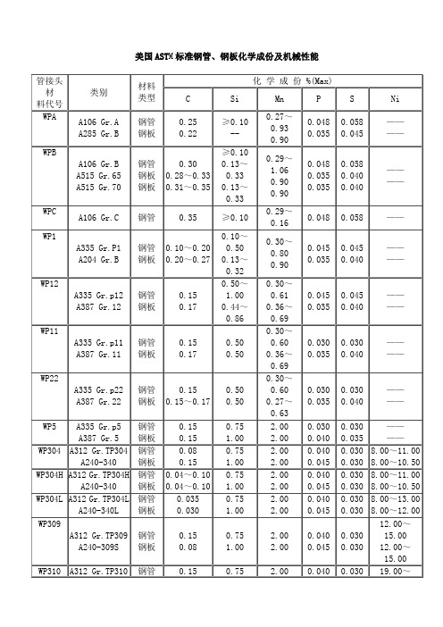
钢管
钢板
0.08
0.15
0.75
1.00
2.00
2.00
0.040
0.045
0.030
0.030
8.00~11.00
8.00~10.50
WP304H
A312 Gr.TP304H
A240-340
钢管
钢板
0.04~0.10
0.04~0.10
0.75
1.00
2.00
2.00
0.040
0.045
2.00
0.040
0.045
0.030
0.030
9.00~13.00
9.00~12.00
WP321H
A312 Gr.TP321H
A240-321
钢管
钢板
0.040~0.10
0.040~0.10
0.75
1.00
2.00
2.00
0.040
0.045
0.030
0.030
9.00~13.00
9.00~12.00
美国astm标准钢管钢板化学成份及机械性能管接头料代号类别材料类型simnniwpaa106graa285grb钢管钢板0250220100270930900048003500580045wpba106grba515gr65a515gr70钢管钢板钢板030028033031035010013033013033029106090090004800350035005800400040wpca106grc钢管03501002901600480058wp1a335grp1a204grb钢管钢板0100200200270100500130320300800900045003500450040wp12a335grp12a387gr12钢管钢板0150170501000440860300610360690045003500450040wp11a335grp11a387gr11钢管钢板0150170500500300600360690030003500300040wp22a335grp22a387gr22钢管钢板0150150170500500300600270630030003500300040wp5a335grp5a387gr5钢管钢板0150150751002002000030004000300035wp304a312grtp304a240340钢管钢板008015075100200200004000450030003080011008001050wp304ha312grtp304ha240340钢管钢板004010004010075100200200004000450030003080011008001050wp304la312grtp304la240340l钢管钢板00350030075100200200004000450030003080013008001200wp309a312grtp309a240309s钢管钢板01500807510020020000400045003000301200150012001500wp310a312grtp310钢管015075200004000301900a240310s钢板00810020000450030220019002200wp347a312grtp347a240347钢管钢板008008075100200200004000450030003019001300190013
2016-2017年ASTM标准的编号方法(总结)
ASTM标准的编号方法ASTM标准编号形式为:标准代号+字母分类代码+标准序号+制定年份+标准英文名称。
示例:ASTM A311M-95(1996) 冷制合金钢棒材标准规范ASTM+A+311M+95(1996)+冷制合金钢棒材标准规范标准代号+字母分类代码+标准序号+制定年份+标准英文名称说明:1. 标准序号后带字母M的为米制单位标准,不带字母M的为英制单位标准。
2. 制定年限后面括号内的年代为标准重新审定的年代。
3. a.b.c......表示修订版次。
4. 字母分类代码为:A ——黑色金属B ——有色金属(铜,铝,粉末冶金材料,导线等)C ——水泥,陶瓷,混凝土与砖石材料D ——其它各种材料(石油产品,燃料,低强塑料等)E ——杂类(金属化学分析,耐火试验,无损试验,统计方法等)F ——特殊用途材料(电子材料,防震材料,外科用材料等)G ——材料的腐蚀,变质与降级工会党支部工作总结[工会党支部工作总结] xxxx年,我们工会党支部在师直党工委的正确领导下,认真学习贯彻“三个代表”重要思想,学习党的十六届四中全会精神,自觉用“三个代表”重要思想指导工作,进一步加强党支部的建设,在工作中较好的发挥了政治核心和战斗堡垒作用,工会党支部工作总结。
现将xxxx年的支部工作情况总结汇报如下。
一、努力加强党支部的思想建设、组织建设和作风建设1.思想建设:在工会全体党员中继续深入学习邓小平理论和“三个代表”的重要思想。
在党的十六大四中全会召开以后,认真学习大会的精神和文件,特别是对全会讨论通过的《关于加强中国共产党执政能力建设的决定》,不仅在支部成员内部认真学习贯彻,而且还在工会全体工作人员中传达贯彻学习。
坚持严肃认真地进行党员民主评议工作,切实解决党支部、党员中存在的问题和不足,努力提高全体党员的思想认识,为圆满完成全年的各项工作,提供思想保证。
同时开好领导班子民主生活会,认真征集职工意见,认真开展批评与自我批评,找差反思,并进行认真整改,进一步完善领导班子的工作。
ASTM-A钢材标准

热锻及冷加工碳素钢和合金钢棒
Standard Specification for Steel Bars, Carbon and Alloy, Hot-Wrought, General Requirements for
A31-04
钢铆钉及铆钉和压力容器用棒材
Standard Specification for Steel Rivets and Bars for Rivets, Pressure Vessels
A121-99(2004)
镀锌刺钢丝
Standard Specification for Mettalic-Coated Carbon Steel Barbed Wire
A123/A123M-02
钢铁产品的锌镀层(热浸镀锌)技术规范
Standard Specification for Zinc (Hot-Dip Galvanized) Coatings on Iron and Steel Products
Standard Specification for Heat-Treated Carbon Steel Joint Bars, Microalloyed Joint Bars, and Forged Carbon Steel Compromise Joint Bars
A53/A53M-04
无镀层热浸的、镀锌的、焊接的及无缝钢管的技术规范
A34/A34M-01
磁性材料的抽样和采购试验的标准惯例
Standard Practice for Sampling and Procurement Testing of Magnetic Materials
A36/A36M-04
碳素结构钢技术规范
ASME标准钢号和中国钢号对照表

Mterial
材质类型
American code美国牌号
Chemical化学成分%
Mechnics
机械性能≮
Equalchinese code似近中国牌号
ASME
AISI
B&W代号
C
Si
Mn
Mo
Cr
Ni
V
P≤
S≤
σb
σs
δ%
ψ%
一:heating surface tube、header and pipe受热面管子、集箱和管道用钢管
0.060
330
205
--
--
20
Q235A
15
A500B
≤0.30
--
--
---
--
--
--
0.050
0.063
400
290
23
--
Q235AF
16
板型棒
SA-283C
≤0.24
0.15-
0.40
≤0.90
--
--
--
Cu≥0.20
0.040
0.035
385-485
205
25
--
Q235A
17
SA-283D
A696C
≤0.32
0.15-
0.35
≤1.04
--
--
--
--
0.035-0.045
0.045
485
275
18
--
30 . 35
21
1Mn-0.5Cr
板型棒
A588A
--
--
≤0.19
0.30-
ASTM-A钢材标准

电话和电报线路用镀锌"铁"丝规格
Standard Specification for Zinc-Coated (Galvanized) Iron Telephone and Telegraph Line Wire
A116-00
镀锌钢丝编织栏栅网
Standard Specification for Metallic-Coated, Steel Woven Wire Fence Fabric
A29/A29M-04
热锻及冷加工碳素钢和合金钢棒
Standard Specification for Steel Bars, Carbon and Alloy, Hot-Wrought, General Requirements for
A31-04
钢铆钉及铆钉和压力容器用棒材
Standard Specification for Steel Rivets and Bars for Rivets,Pressure Vessels
钢质螺旋道钉
Standard Specification for Steel Screw Spikes
A67-00
热加工低碳钢和高碳钢垫板技术规范
Standard Specification for Steel Tie Plates, Low-Carbon and High-Carbon Hot-Worked
A135-01
电阻焊钢管
Standard Specification for Electric-Resistance-Welded Steel Pipe
A139/A139M-04
电熔(电弧)焊钢管(4英寸以上的)
Standard Specification for Electric-Fusion (Arc)-Welded Steel Pipe (NPS 4 and Over)
- 1、下载文档前请自行甄别文档内容的完整性,平台不提供额外的编辑、内容补充、找答案等附加服务。
- 2、"仅部分预览"的文档,不可在线预览部分如存在完整性等问题,可反馈申请退款(可完整预览的文档不适用该条件!)。
- 3、如文档侵犯您的权益,请联系客服反馈,我们会尽快为您处理(人工客服工作时间:9:00-18:30)。
(generated by a spring force) onto a surface of the material under test. The ratio of the rebound velocity to the impact velocity of the impact body is a measure of the hardness of the material under test. 3.1.4 surface finish—all references to surface finish in this test method are defined as surface roughness (that is, Ra = average roughness value, AA = arithmetic average). 3.1.5 verification—checking or testing the instrument to ensure conformance with this test method. 4. Significance and Use 4.1 Hardness of a material is a poorly defined term that may have many meanings depending on the type of test performed and the expectations of the person involved. The Leeb hardness test is of the dynamic or rebound type, which primarily depends both on the plastic and on the elastic properties of the material being tested. The results obtained are indicative of the strength and dependent on the heat treatment of the material tested. 4.2 The Leeb hardness test is a superficial determination only measuring the condition of the surface contacted. The results generated at that location do not represent the part at any other surface location and yield no information about the material at subsurface locations. A. GENERAL DESCRIPTION OF INSTRUMENTS AND TEST PROCEDURE FOR LEEB HARDNESS TEST 5. Apparatus 5.1 The instrument used for Leeb hardness testing consists of (1) an impact device that is equipped with a tungsten carbide ball or synthetic diamond tipped impact body, an induction coil velocity measuring assembly, and a support ring, and ( 2) an electronic digital display hardness indicating device. 5.2 Impact Devices—There are six types of impact devices used in Leeb hardness testing. These are the D, DC, D+15, G, C, and the E impact units. Brief descriptions of the types of devices and their common applications are given in Appendix X1. 5.3 Summary of Test Method—During a hardness test, an impact body with a spherically shaped tungsten carbide or diamond tip impacts under spring force, the test surface from which it rebounds. The impact and rebound velocities are
1. Scope 1.1 This test method covers the determination of the Leeb hardness of steel, cast steel, and cast iron (Part A), including the methods for the verification of Leeb hardness testing instruments (Part B), and the calibration of standardized test blocks (Part C). 1.2 The values stated in inch-pound units are to be regarded as the standard. The values given in parentheses are for information only.
2. Referenced Documents 2.1 ASTM Standards: E 691 Practice for Conducting an Interlaboratory Study to Determine the Precision of a Test Method2 3. Terminology 3.1 Definitions: 3.1.1 calibration—determination of the values of the significant operating parameters of the instrument by comparison with values indicated by a reference instrument or by a set of reference standards. 3.1.2 Leeb hardness number—a number equal to the ratio of the rebound velocity to the impact velocity of a 3-mm or 5-mm (based on the type of impact device) diameter tungsten carbide ball or diamond tipped impact body, multiplied by 1000.
Rebound Velocity L 5 Impact Velocity 3 1000
The Leeb hardness number is followed by the symbol HL with one or more suffix characters representing the type of impact device. 3.1.3 Leeb hardness test—a dynamic hardness test method using a calibrated instrument that impacts a spherically shaped carbide ball or diamond tipped body with a fixed velocity
Designation: A 956 – 02
Standard Test Method for
Leeb Hardness Testing of Steel Products1
This standard is issued under the fixed designation A 956; the number immediately following the designation indicates the year of original adoption or, in the case of revision, the year of last revision. A number in parentheses indicates the year of last reapproval. A superscript epsilon (e) indicates an editorial change since the last revision or reapproval.
1 This test method is under the jurisdiction of ASTM Committee A01 on Steel, Stainless Steel, and Related Alloys and is the direct responsibility of Subcommittee A01.06 on Steel Forgings and Billets. Current edition approved July 10, 2002. Published August 2002. Originally published as A 956–97. Last previous edition A 956–00. Leeb and Equotip are registered trademarks used with permission of Proceq SA. 2 Annual Book of ASTM Standards, Vol 14.02.