CODESYS V3 基础编程指南2.pdf
《PLC综合开发利器——CoDeSys基础编程及应用指南》_LGJ_V4(1)

PLC综合开发利器——CoDeSys基础编程及应用指南目录第0章前言 (7)第1章概述 (8)1.1IEC61131-3标准 (8)1.1.1IEC 61131简介 (8)1.1.2PLCopen组织概况 (9)1.1.3IEC 61131-3编程语言 (9)1.1.4IEC 61131-3标准语言的特点 (10)1.2软PLC-C O D E S YS (11)1.2.1软PLC控制方案 (12)1.2.2软PLC的发展方向 (13)1.3C O D E S YS概述 (14)1.3.1CoDeSys自动化解决方案 (14)1.3.2CoDeSys实时核 (16)1.4软件的安装 (17)1.4.1安装所需的软硬件要求 (18)1.4.2安装 (18)1.4.3启动编程软件 (18)1.4.4帮助 (18)1.4.5CoDeSys开发系统 (19)1.5获取资料、插件和技术论坛 (22)第2章CODESYS结构 (23)2.1软件模型 (23)2.1.1软件模型概述 (23)2.1.2软件模型的特点 (24)2.2设备 (24)2.2.1设备 (24)2.2.2设备编辑器 (27)2.3应用 (28)2.3.1任务 (28)2.3.2库文件 (38)2.3.3全局变量和局部变量 (48)2.3.4访问路径 (50)2.4程序组织单元 (51)2.4.1程序组织单元结构 (51)2.4.2函数 (53)2.4.3功能块 (56)2.4.4程序 (60)2.4.5创建的原则 (62)2.5应用对象 (62)2.5.1采样跟踪 (62)2.5.2持续变量 (68)2.5.3数据单元类型 (69)2.5.4全局网络变量 (70)2.5.5配方管理器 (71)第3章公共元素及变量 (73)3.1公用元素 (73)3.1.1字符集 (73)3.1.2分界符 (73)3.1.3关键字 (75)3.1.6空格和注释 (78)3.2变量的表示和声明 (82)3.2.1变量 (82)3.2.2标识符 (82)3.2.3变量声明 (82)3.3数据类型 (84)3.3.1标准数据类型 (84)3.3.2标准的扩展数据类型 (89)3.3.3自定义数据类型 (96)3.4变量的类型和初始化 (107)3.4.1变量的类型 (107)3.4.2变量的初始化 (109)3.5变量声明及字段指令 (110)3.5.1变量匈牙利命名法 (110)3.5.2字段Pragma指令 (111)第4章编程语言 (113)4.1指令表(IL) (114)4.1.1指令表编程语言简介 (114)4.1.2连接元素 (115)4.1.3操作指令 (118)4.1.4函数及功能块 (123)4.1.5应用举例 (124)4.2梯形图(LD)/功能块(FBD) (126)4.2.1梯形图/功能块图编程语言简介 (126)4.2.2连接元素 (128)4.2.3应用举例 (137)4.3结构化文本(ST) (141)4.3.1结构化文本编程语言简介 (141)4.3.2指令语句 (143)4.3.3应用举例 (153)4.4顺序流程图(SFC) (157)4.4.1顺序流程图编程语言简介 (158)4.4.2SFC的结构 (160)4.4.3应用举例 (172)4.5连续功能图(CFC) (173)4.5.1连续功能图编程语言结构 (173)4.5.2连接元素 (175)4.5.3CFC的组态 (182)4.5.4应用举例 (183)第5章指令系统 (184)5.1位逻辑指令 (184)5.1.1基本逻辑指令 (184)5.1.2置位优先与复位优先触发器指令 (189)5.1.3边沿检测指令 (192)5.2定时器指令 (194)5.2.1定时器 (194)5.3计数器指令 (198)5.3.1计数器简介 (198)5.3.2计数器指令 (198)5.4数据处理指令 (202)5.4.1选择操作指令 (202)5.5运算指令 (214)5.5.1赋值指令 (214)5.5.2算术运算指令 (214)5.5.3数学运算指令 (217)5.5.4地址运算指令 (221)5.6数据转换指令 (223)5.6.1数据类型转换指令 (223)第6章基础编程 (231)6.1基本编程操作 (231)6.1.1启动CoDeSys (231)6.1.2PLC程序文件的建立 (233)6.2通讯参数设置 (236)6.2.1启动Gateway Server 和PLC (236)6.3程序下载/读取 (239)6.3.1编译 (239)6.3.2登入下载 (239)6.3.3在线监控 (243)6.4程序调试 (246)6.4.1复位功能 (246)6.4.2调试工具 (248)6.5仿真 (251)6.5.1离线仿真 (251)6.6PLC脚本功能 (253)6.7程序隐含检查功能 (254)第7章程序结构 (258)7.1系统程序和用户程序 (258)7.2用户程序结构 (258)7.2.1常用的编程方法 (258)7.3锁存电路 (262)7.3.1创建锁存电路 (262)7.3.2锁存电路的实际应用 (265)第8章可视化界面建立及应用 (267)8.1C O D E S YS可视化界面 (268)8.2基本操作 (269)8.2.1创建可视化界面 (269)8.2.2添加工具 (269)8.2.3对齐工具 (270)8.2.4删除工具 (270)8.3工具 (270)8.3.1基本工具 (270)8.3.2通用控制工具 (275)8.3.3测量控制 (286)8.3.4灯/开关/位图 (292)8.3.5特殊控制 (294)8.3.6报警管理 (301)8.4视图的建立及编辑 (307)8.4.1应用举例 (307)第9章模拟量闭环控制的实现 (319)9.1模拟量闭环控制 (319)9.1.2闭环控制的主要性能指标 (320)9.2C O D E S YS的闭环控制功能 (321)9.2.1CoDeSys控制方法 (321)9.2.2使用CoDeSys实现闭环控制 (321)9.2.3模拟量输入数据整定 (323)9.2.4模拟量输出数据整定 (325)9.2.5输入数据滤波 (326)9.3数字PID控制器 (333)9.3.1PID控制原理 (333)9.3.2标准PID控制器 (335)9.3.3固定采样频率的PID控制器 (337)9.3.4PD控制器 (338)9.4数字PID控制的改进算法 (340)9.4.1积分分离控制器 (340)9.4.2带死区的PID控制器 (341)9.5闭环控制实例 (342)9.5.1PID参数整定 (342)9.5.2简易压紧机的控制实例 (343)第10章控制系统工程实例 (352)10.1.1电动机点动运行 (352)10.1.2控制电动机正、反转运行 (355)10.1.3电动机Y-△启动控制 (361)10.1.4恒压变频供水控制系统 (366)10.1.5气动分度盘正、反转控制 (371)10.1.6液位自动控制 (377)10.1.7火警报警系统 (383)10.1.8抢答器控制系统 (385)10.1.9交通灯信号控制程序 (388)10.1.10停车场管理 (393)第11章通信网络基础 (395)11.1通信技术基础 (395)11.1.1通信系统的结构 (395)11.1.2通讯传输模式 (396)11.1.3数据传送方式 (396)11.1.4数据传送介质 (400)11.2串行通信基础及协议标准 (405)11.2.1基本概述 (405)11.2.2串口通讯接口标准 (407)11.3现场总线系统 (409)11.3.1现场总线技术 (409)11.3.2现场总线的特点 (410)11.3.3IEC 61158标准 (413)11.3.4FCS与DCS的基本要点及区别 (416)11.3.5现场总线的发展历程及发展现状 (417)11.4工业以太网 (419)11.4.1TCP/IP (419)11.4.2TCP/IP的工作方式 (420)11.4.3IEEE 802通信标准 (422)11.4.4工业控制网络的拓扑结构 (424)第12章常用工业现场总线及介绍 (430)12.1CAN通讯 (430)12.1.2CANopen物理层 (439)12.1.3PDO通讯示例 (441)12.1.4SDO通信示例 (447)12.2M ODBUS网络基础 (452)12.2.1数据链路层 (453)12.2.2协议描述 (455)12.2.3Modbus串行的两种传输模式 (458)12.2.4Modbus功能码 (462)12.2.5Modbus 物理层 (465)12.2.6Modbus 串口的通讯组态 (470)12.3E THER CAT网络基础 (475)12.3.1EtherCAT物理层 (475)12.3.2EtherCAT硬件组成 (480)12.3.3EtherCAT运行原理 (480)12.3.4EtherCAT通讯模式 (489)12.3.5EtherCAT状态机 (493)12.3.6EtherCAT伺服驱动器控制应用协议 (495)12.3.7EtherCAT主从站通讯配置示例 (502)12.4PROFINET网络基础 (509)12.4.1PROFINET物理层 (509)12.4.2PROFINET (513)12.4.3PROFINET协议架构 (516)12.4.4同步实时通信 (520)12.4.5PROFINET主从站通讯配置 (523)12.5E THER N ET/IP网络基础 (532)12.5.1EtherNet/IP物理层 (532)12.5.2EtherNet/IP运行原理 (537)12.5.3EtherNet/IP网络性能性能指标 (543)12.5.4EtherNet/IP通讯配置 (544)第13章附录 (550)13.1附录A ST指令快查 (550)13.2附录B标准库FUN及FB快查 (551)13.3附录C常用快捷键 (553)13.3.1快捷输入 (554)13.4附录D参考文献 (556)第0章前言CoDeSys是德国3S公司的PLC编程软件,本书主要以介绍该软件的PLC编程功能。
CoDeSys编程简介 53页 0.5M 高清版

第一章安装CoDeSys2.1目前只能配置在WINDOWS-9x 或 -2000或-NT操作系统下,以下操作都在这几种系统下进行。
一、EPEC Can-card 卡安装EPEC PC-CAN卡用于CAN总线到PC的通讯转换,装于PC的PCMCIA插槽中。
1、在WINDOWS-9X,WINDOWS2000下的安装:1) 在关机状态下,插入PC-CAN 卡到笔记本电脑的PCMCIA插槽内。
2)开机后,系统自动发现新硬件,插入安装盘,自动搜索安装盘即可自行安装;也可指定安装位置于\CoDeSysSetupEng\Drivers\CANCard\WIN95或WIN2000安装。
2、在WINDOWS NT下的安装:1)关机,插入PC-CAN 卡到 PCMCIA插槽内.2)开机,以管理员模式进入:−操作系统自动发现新硬件,插入安装盘, 自动搜索安装盘即可自行安装;−或指定安装位置于\CoDeSysSetupEng\Drivers\0-01\WINDOWS进行安装。
或运行 \CoDeSysSetupEng\Drivers\0-01\Winnt\Setup.exe,根据提示进行安装。
−当提示出现是否重新启动时选择重新启动。
−重新启动后打开Control Panel (Start / Settings / Control Panel)。
−打开Devices窗口寻找line CAN。
−检查它的status是否started,设置startup为automatic。
如PC-CAN卡未安装成功,查看系统硬件是否有冲突;关机后将其他的卡取出,按上述步骤重装。
二、CANMoon 安装1.在硬盘创建\…\CANMoon\;2.拷贝安装盘\...\CodesysSetupEng\CANMoon_Ver_1_2\*.*到硬盘\...\CANMOON\中;3.拷贝安装盘\...\CodesysSetupEng\drivers\windows\system\*.*到..\CANMOON\中;4.将硬盘\...\CANMOON\中CANMOON.EXE建立快捷方式到桌面。
CodeSys 应用说明文档

CodeSys 应用说明文档1.工程创建及编程入门
请参考文件CoDeSys 自动化开发平台基础编程入门.pdf
2.工程组成说明
2.1. 设备说明
设备名: 只是一个设备的名称,可以在其属性中更改
设备类型: 是设备的类型,名称是固定的
可以根据需要更改设备类型,以便于本机调试和目标机调试,
2.2. 程序说明
程序运行单元(PRG): 是一个可以运行的逻辑,能够被添加到任务中运行.
程序功能块(FB): 是一个完成某种功能的程序块,不能单独运行,只能在PRG中被调用时运行(必须先定义). 函数(Function): 是一个完成某种功能的程序块,不能单独运行,只能在PRG中被调用时运行(可以直接调用). 注意:
程序功能块(FB)和函数的区别:
1.程序功能块(FB)必须先定义,才能被使用,(类型于一个变量,必须先定义,才能在程序中使用)
但函数(Function)可以直接被调用,不必定义.
2.程序功能块(FB),可以有多个返回值,但函数(Function)只能有一个返回值;
2.3. 视图说明:
目标视图分辨率设置:
视图分辨率及名称设置:
导入位图
在视图添加背景图片
在视图中显示图片
在视图中添加Image控件,
图片的旋转
在视图中添加多边形控件,然后手动多边形的5个点,形成一写的图形,然后手动图片的中心点,
到要需要旋转的位置
控件的输入响应
2.4. 程序的调试选择程序运行的目标机
●程序单步调试
程序编译正确后,选择登录后,程序会下载到目标机上,并处于停止状态,点击运行后,程序才会跑起来,在调试时,可以监视变量的变化
暂停调试时,选择停止,停止调试时选择登出.
●直接下载程序。
玩转codesys入门篇
玩转codesys入门篇
展开全文
1.安装
官方网站上或其他渠道下载安装包,一路默认安装即可,安装完成后电脑右下角如下图显示三个图标
2CmContainers已经连接
CODESYS Gateway SysTray(running)
CODESYS Control Win SysTray(stopped)
2.启动及新建项目
点击桌面codesys图标,软件启动动画如图
新建一个 standard project
3.基本操作
新建项目后可以在plc项目里添加Enum,Struct,FunctionBlock,Program,Task,如下图所示
添加操作基本都为右键->添加对象->...不同项的添加对象内容不同
同时,codesys能够配置多个任务,任务调用不同的程序段,每个任务可以手动设置执行优先级及循环周期
4.通讯配置
在device上可以进行通讯配置,这时网关指示绿色,最右侧指示灰色
所以要先start plc,启动成功后,图标由灰色变为彩色,进入running状态
然后进行扫描,选中本地pc,确定后将最右侧指示由灰色变为绿色即为成功
5.程序在线运行
此时可对程序进行编译,然后点击登录到
登录完成后状态如下图所示,登录完成,但程序处于停止状态
点击启动,启动成功后显示运行状态
双击程序段可监控变量在线执行状态,可以看到两段代码由于执行周期不同分别显示不同数值。
CoDeSys编程手册范本

声明部分:
FUNCTIONFct:INT
VAR_INPUT
PAR1:INT;
PAR2:INT;
PAR3:INT;
END_VAR
程序部分:
LDPAR1
MULPAR2
DIVPAR3
STFct
在结构文本中功能的调用可以作为表达式中的一个操作数。
功能不会有任何内部条件,这就是说,调用带有相同的输入变量功能将会返回相同的输出结果。
为了通讯的目的,CoDeSys有一个符号接口和一个动态数据交换(DDE)接口。网关服务器和OPC服务器和动态数据交换服务器是CoDeSys的标准安装软件包的组件。
使用恰当的目标设置能够把相同的CoDeSys工程加载到不同的目标系统中,可以通过目标文件来加载这些目标设置。
通过当前的目标设置来激活网络全局变量和参数管理器。可以在控制器网络中交换数据。
例如:
FBINST是一个功能块类型的局部变量,它包含了输入变量xx和输出变量yy。当FBINST是通过输入帮助插入到了ST程序中,将显示如下的调用:FBINST1(xx:=,yy=>)。
在调用输入输出变量时:
请注意:功能块的输入输出变量作为指针来处理。因此在调用一个功能块时,常量是不能赋予VAR_IN_OUT并且从外部没有读和写的权限。
FUNCTION_BLOCKFUB
VAR_INPUT
PAR1:INT;
PAR2:INT;
END_VAR
VAR_OUTPUT
MELERG:INT;
VERGL:BOOL;
END_VAR
在IL的执行部分:
LDPAR1
MULPAR2
CODESYS V3 基础编程指南
1. CoDeSys 侧 Modbus TCP 主站配置 如使用 CoDeSys 所配置的 Modbus TCP 的主站需要首先对主站进行配置,此外,需要对从站的
配置也在主站的参数下也作相应的配置,具体步骤在下文会有详细的介绍。 1) 添加主站 添加 Modbus TCP 硬件设备,由于 Modbus TCP 基于以太网的通讯,故先添加硬件,鼠标右键
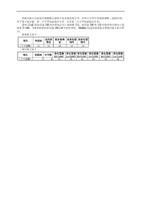
图 12.x Modbus 串行通信从站设置 从站地址:设置从站的站地址,1~247 有效。 响应超时:设置从站的响应超时时间,如果超过该时间从站还没有相应主站,则主站认为该从 站有通讯故障。 6) 设置从站的通讯通道 如图 12.x 所示,在该设置选项中,用户可以自定义从站的 Modbus 通讯通道,但必须与实际的 从站硬件相匹配,按下“添加通道”后,系统会自动弹出对话框,用户可以直接选择访问功能码、 地址偏移、数据长度及通讯周期时间等。
图 12.x Modbus 串行通信主站配置 传输模式:选择 RTU 或者 ASCII 码。 响应超时(ms):指主站等待从站响应的时间间隔。如果在这段时间中从站没有发出响应,主 站将会请求下一个从站。此时输入的值会认为是每个从站的缺省值。在 ⇘ 从站配置页面,可单独 为每个从站设置合适的时间间隔。 框架之间的时间(ms):指主站接收上一个响应数据帧到下一个请求数据帧之间等待的时间间 隔。这个参数可用于调节数据交换率。 至此,主站的配置结束,接下来,需要对主站连接的从站做相应的配置。 5) 主站下配置第三方的 Modbuቤተ መጻሕፍቲ ባይዱ 串行设备 在 CoDeSys 的设备树下,鼠标选中主站,右键选择“添加设备” ,选择添加 Modbus 串口设备 从站,Modbus 串行通信从站配置界面如图 12.x 所示。
Turck CoDeSys 3软件与程序可编程控制器应用指南说明书

Your Global Automation Partner Application Guide2 Turck Inc. | 3000 Campus Drive, Minneapolis, MN 55441 | T +1 763 553-7300 | F +1 763 509-7709 | Create a control system without a panelThe CoDeSys 3 (IEC 61131-3) software provides a powerful control environment supporting multiple common programming languages including ladder, structured text, function block diagram, and sequential function chart. This software can be downloaded for free at .A small button podium may be used to house items that must be enclosed in the panel.Turck programmable controllers provide up to IP68/IP69k protection, ideal for complete control of a system without the need for an enclosed control cabinet. These devices can function as a network master for remote I/O, additionally the flexible BL67 modular system allows for a variety of local I/O modules.3These devices can function as a network master or remoteI/O over multiple industrial fieldbus protocols including:*Indicates length in meters.BL67-PG-EN-V3TBEN-Lx-PLC-01■-40...+70 °C operating temperature ■IP67 Protection■Up to 32 local I/O modules(Discrete, analog, IO-Link, RFID, serial, etc.)■-40...+70 °C operating temperature ■IP68/IP69K Protection ■Onboard serial andconfigurable discrete I/O4 Turck Inc. | 3000 Campus Drive, Minneapolis, MN 55441 | T +1 763 553-7300 | F +1 763 509-7709 | Connect BL Ident RFID to any PLC5BL Ident Tags■Read/write times up to 2000 bytes/sec possiblewith FRAM Technology■Standard tags include 128 byteEEPROM and 2 kbyte FRAM tags■Available in high temperature packages, capable of up to 210 °C■Variety of tags available: bolts, ID-cards, adhesivelabels, autoclave, laundry, FDA approved■Data storage for 10 years at ambient temperatures■Flexible assembly lines: for custom build operations the required BOM could be stored into the tag and read out at each station ■Replace existing barcode system:barcode is reapplied due to paint or heat treatment where RFID can survivePLC6 Turck Inc. | 3000 Campus Drive, Minneapolis, MN 55441 | T +1 763 553-7300 | F +1 763 509-7709 | Connect fieldbus techology products to analog input devicesBL remote is a feature available on some gateway products. This feature allows bridging of device level networks to Ethernet. In this example, BL67 is operating on EtherNet/IP and drops down to the BL compact station using BL remote.Rod Style Series: ■Rugged rod style housing toallow operation in high shock and vibration environments ■Hydraulic cylinder applications where rod can withstand up to 5000 PSI continuously■Various analog output options ■16-bit resolution■Stroke length up to 168 inchesQ-track™ Series:■■ ■ ■ ■ ■Level Probe Series: ■Ideal for continuous level monitoring ■Uses magnetostrictive technologyto monitor float location■Analog output■Programmable monitoring span ■Stroke length up to 288 inches ■FM approved7Analog Sensors:■Pressure, temperature, sensors and transmittersfor use in pneumatic and hydraulic applications■Programmable digital read out flow sensors ■Highly reliable and precise temperature sensors ■Ultrasonic sensors■Linear analog sensors with wide range ofhousing styles and output options8 Turck Inc. | 3000 Campus Drive, Minneapolis, MN 55441 | T +1 763 553-7300 | F +1 763 509-7709 |BL67 I/O System can include digital, analog, IO-Link and RFID.2Parker Valve ManifoldsParker supplies a BL67 valve adapter base to directly connect Isys ISO and Micro valve banks to the Turck BL67 modular I/O system. Standard TurckBL67-16DO-0,1A-P output modules insert into the adapter base to provide direct control of up to 32 valve solenoids.Contact a local Parker distributor to order BL67 valve adapter and Parker valve banks.1Connect BL67 to valve banks with molded cables and discrete outputs, IO-Link, or direct connection9Possible Valve Bank Combinations■Channel-relatedshort-circuit monitoring■Wire-break detection■Configurable current monitoring ■Connection of multiple valve banksfrom different manufacturers■Integration of valve banks with digital output modules with 4, 8 or 16 channelsStandard and custom cordset lengthsThe 16-channel specially developed for switching valve banks. It features:10 Turck Inc. | 3000 Campus Drive, Minneapolis, MN 55441 | T +1 763 553-7300 | F +1 763 509-7709 | Hoist and hoist control systems for stage rigging systems move lights, sets and people using gear motors, brakes and winches.Amusement Machine groups product into case quantities and applies shrink film. Encoder tracks length of product ensuring the bar carrying film does not touch product.Packaging Encoder tracks rotations of a drum used to store cable.Cable ManagementVia SSIVia High Speed CounterConnect BL67 to rotary position sensorsAutomotive A shaft encoder is mounted to the drive rollers of a dynamometer to provide velocity feedback.11Features of QR24Rotary Position Sensors: ■Non-contact position measurement ■SSI communication interface ■Bus interface to CANopen ■Rugged IP68/IP69K rating■Highly resistant to noise interference ■Extremely fast (up to 12,000 RPM) andprecise (up to 29 bit resolution) ■Easy setup: IO-Linkparameterization via Pactware ■Available with analog andincremental outputsFeatures ofIncremental Encoders:■Optical technology■Solid and hollow shaft models ■Differential and single-endedmodes of operation■High noise immunity and precision ■Extremely fast (up to 12,000 RPM) ■Standard M12 and M23 connection12 Turck Inc. | 3000 Campus Drive, Minneapolis, MN 55441 | T +1 763 553-7300 | F +1 763 509-7709 | BL 67 I/O System■Rugged IP 67 construction allowsfor mounting directly on a machine without the use of an enclosure ■Modular design allows for variousI/O connections: up to 32 electronic modules, 256 digital or 64 analog■Support current and voltage I/O, RTDs, thermocouples, CAN Valve interface, RS232, RS422/485 and serial synchronous interfaces■Support of PROFIBUS, DeviceNet,CANopen, EtherNet/IP , Modbus TCP/IP , and PROFINET fieldbus■System diagnostic and per point diagnostic ■Fast and easy connectorization using7/8-16 UN Minifast ®, M12 Eurofast ®, M8 Picofast ® or M23 Multifast ® ■Configuration using free I/O-Assistantsoftware or rotary switchesEncoders BL ident (RFID)Sensors Solenoids Motor StartersTCP/IP13Possible CombinationsColor VisionBar Code VisionMachine Vision■Gray scale pattern and colorspectrum analysis■Two convenient form factors: one-piece PresencePLUS P4or compact PresencePLUS Pro sensor with a separate DIN-mountable controller ■Rugged IP 68-rated models suitablefor washdown applications* Indicates length in meters.Features of PresencePLUS ® Systems:■All PresencePLUS vision sensorsinclude built-in serial, EtherNet/IP and Modbus TCP/IP drivers with 4 (P4) or 6 (PROII) programmable I/O. A PresencePLUS sensor, with the Turck BL67 delivers expanded I/O, DeviceNet, PROFIBUS or PROFINET connectivity ■General-purpose or dedicated-function vision sensors■Discrete I/O on-board ■Wide range of mountingbrackets, lighting and lenses remote TEACH functionality to adjust image without PC ■Simple and intuitive userinterface with three-step, point-and-click operation■Rugged IP67 construction allows for mounting directly on a machine without the use of an enclosure ■Modular design allows for various I/O connections: up to 32 electronic modules, 256 digital or 64 analog ■Support current and voltage I/O, RTDs, thermocouples, CAN Valve interface, RS232, RS422/485 and serial synchronous interfaces ■System diagnostic andper point diagnostic■Fast and easy connectorization using7/8-16 UN Minifast®, M12 Eurofast®,M8 Picofast® or M23 Multifast®■Configuration using free I/O-Assistantsoftware or rotary switches■Support a wide variety offieldbuses including:»EtherNet/IP™»Modbus TCP/IP»PROFINET»DeviceNet™»PROFIBUS®-DP»CANopenBL67 I/O SystemInput/Output DevicesEncoders BL ident (RFID)Sensors SolenoidsConnect BL67 to wireless networkswith DX80 wireless gatewaysTCP/IP214 Turck Inc.|3000 Campus Drive, Minneapolis, MN 55441|T +1 763 553-7300|F +1 763 509-7709|15Possible Wireless Combinations* Indicates length in meters.Factory AutomationAgriculture and WaterTraffic ManagementCommercial andConsumer Monitoring16 Turck Inc. | 3000 Campus Drive, Minneapolis, MN 55441 | T +1 763 553-7300 | F +1 763 509-7709 | Stand alone I/O solutions powered by ARGEEWhen the door is closed the input sensor is on.No ARGEE actions take place in this condition.When the freezer door is open for more than 10seconds a warning light is turned on.With the freezer door open for more than 20seconds an audible alarm is turned on as well.When the door is closed at any time, the light and alarm are turned off and the timers are reset to zero.Door ClosedDoor OpenedDoor Opened for 20 Secs or MoreProgramming with an FLC (field logic controller) powered by ARGEE for a stand alone application could not be simpler. In the ARGEE Flow editor, a ladder like diagram editor, users use a drop down menu to select inputs, operations and outputs. When the program is running, the FLC carries out the program logic. Take the following stand alone freezer door application for example:17• This step in the program will monitor the door.• When the door is closed, our input value is on.• With this condition , we utilize the Boolean NOT operation to prevent Timer 1 and Timer 2 from starting.•With this logic, when the door opens, the action of starting Timer 1 and Timer 2 will begin.•When Timer 1 is expired, turn on Output 3 and illuminate our warning light.•When Timer 2 is expired, turn on Output 7 and sound our audible alarm.Slot 2. Input_value_0Time 1 ExpiredTime 2 ExpiredNOT Pass ThroughPass Through Pass Through Pass ThroughPass ThroughTON Timer 1No ActionSlot 2. Output_value_7TON Timer 2Slot 2. Output_value_3No ActionNo Action28 subsidiaries and over 60 representations worldwide!B3106 B 03/16©2016 by Turck Inc. All rights reserved. No part of the publication may be reproduced without written permission.Printed in USA。
CoDeSys编程手册
