VHFD16-16IO1中文资料
Orion VCL-16 E1 + Ethernet PDH 光学多路复用器说明书

Product Brochure & Data SheetVCL - 16 E1 + Ethernet PDH Optical MultiplexerO RION T ELECOM N ETWORKS I NC.RIONTELECOMNETWORKSHeadquarters: Phoenix, Arizona Orion Telecom Networks Inc.20100, N 51st Ave, Suite B240,Glendale AZ 85308Phone: +1 480-816-8672Fax: +1 480-816-0115E-mail:**********************Website: Regional Office: Miami, Florida Orion Telecom Networks Inc.4000 Ponce de Leon Blvd. Suite 470,Coral Gables, FL 33146 U.S.A.Phone: 1-305-777-0419, Fax: 1-305-777-0201E-mail:**********************Website: Product DescriptionFeatures and Highlights1+1 Protection on Optical Path16 E1s+1,10BaseT Ethernet16 E1s+1,10BaseT EthernetFront ViewVCL - 16 E1 + Ethernet PDH Optical MultiplexerVCL - 16Et e net PDH Optical Multiplexer E1 + h r is a point to point high performance optical line transmission equipment, combines 16, ITU-T G.703 compliant standard electrical E1s plus 100BaseT ethernet signal into an optical data stream for transport over fiber optic pairs. Several transmitter options for different cable types and wave-lengths are available. 1+1 optical path redundancy is offered and available as an option.Integrated E1 Plus Ethernet Optical MultiplexerCompact design that performs E1 and Ethernet channel multiplexing & de-multiplexing to an optical outputProvides visible and audible alarm indication Provide Remote power detection (RPD)Low power consumptionOrderwire (EOW) channel for end to end installation and maintenance Local and remote loop back test for diagnostics 1+1 Fiber Path protectionALS (Auto Laser Shutdown) facility for eye safety.10/100M Ethernet Port - 100 Mbps Ethernet data transmission rate complies with IEEE 802.3 E1 is available with 120 Ohms (RJ45) or 75 Ohms (BNC)Supports auto negotiation and flow control (pause)Clock options: internal/loop-timedApplication DiagramVCL - 16 E1 + Ethernet PDH Optical MultiplexerVCL - 16Et e net - Optical Multiplexer Local E1 + h r PDH - VCL - 16Et e net - Optical Multiplexer E1 + h r PDH - RemoteTechnical SpecificationsOpticalSafetyClass 1 LaserAuto Laser Shut Down in the event of fiber break.Ethernet Interface10/100BaseT (optional)Number of Interfaces1Interface RJ45 Ethernet 10BaseT or 100BaseT-TX (auto sensing) Compliance Ethernet Version 2.0 IEEE802.310Base-T & 100Base-TX Activity, Full/half duplex. Interface Rate100 Mbps Ethernet data transmission rateConnector RJ-45Flow Control PauseEnvironment 0Temperature - 5C ~ +55C for operation 00- 40C to +70C for storage 0Humidity 5% to 95% (35C)Physical Width 440 mm Depth 202 mm Height 43.5 mm Weight 2 kg.Rack TypeEIA 19-InchPower Supply Power Input AC, DC, AC + DCDC power DC - 48V(-36~-72V) / DC 24V optional AC powerAC 220V (185~265V)Power consumption 18 Watts maximumOrder Wire Interface Phone set Standard 2-wire phone set Bandwidth 64Kb/s Coding PCMS. No.Product DescriptionPart No.Ordering InformationTechnical specifications are subject to changes without notice.All brand name and trademarks are the property of their respective owners.Revision 06 - February 04, 20132161:1-16E1-ETH-ACDC-1310-040VCL-16E1 + Ethernet PDH Optical Multiplexer 19" Metal box / case 1U High Rack Mount Version Supports :- 16 x E1 [120Ω OR 75Ω 2xDB37 (M)]- 1 x Ethernet [100Mbps, Electrical RJ45 (F)]- 2 x Optical [155Mbps, Duplex FC, 1310nm, 40Km, SMF]- 1 x 100-240V AC Power Supply Input - 1 x (-) 48V DC Power Supply Input- 1 x Systems Core Cables, Installation Accessories, Documentation, System User Manual etc (Set)1.DescriptionPart No.VCL-HRNS 12468E1 75 Ohms Connectorized Cable [DB37F-16BNCF]Cables and Accessories Options VCL-HRNS 12558E1 120 Ohms Connectorized Cable [DB37F-8RJ45F]VCL-HRNS 1240Optical Patch Cord Connectorized Cable [FC-FC, 10m, SM]VCL-HRNS 1242Optical Patch Cord Connectorized Cable [FC-LC, 10m, SM]VCL-HRNS 1243Optical Patch Cord Connectorized Cable [2FC-2LC, 10m, SM]VCL-HRNS 1257Optical Patch Cord Connectorized Cable [2FC-2SC, 10m, SM]VCL-ECON 1173Connector (Attenuator LC-LC (20 db.))VCL-ECON 1187Connector (Attenuator FC-FC (20 db.))VCL-ECON 1198Connector (Attenuator SC-SC (20 db.))Headquarters: Phoenix, Arizona Orion Telecom Networks Inc.20100, N 51st Ave, Suite B240,Glendale AZ 85308Phone: +1 480-816-8672Fax: +1 480-816-0115E-mail:**********************Website: Regional Office: Miami, Florida Orion Telecom Networks Inc.4000 Ponce de Leon Blvd. Suite 470,Coral Gables, FL 33146 U.S.A.Phone: 1-305-777-0419, Fax: 1-305-777-0201E-mail:**********************Website: 。
16路模拟输入输出隔离端子板(宇)
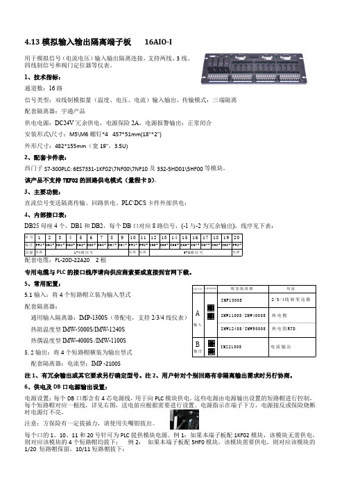
PWR1
2#电 源 输 入 24VDC (冗余)
1#电 源 故障报警
2#电 源 故障报警
0V
PWR2
PWR MON1 PWR MON1 PWR MON2 PWR MON2
保 险 2A 保 险 2A
电源总线+ 电源总线-
DB1-1 DB1-2
1 11 1 11
10 20 10 20
DB2-1 DB2-2
每个口的 1、10、11 和 20 号针可为 PLC 提供模块电源。例 1:如果本端子板配 1KF02 模块,该模块无需供电, 则对应该模块的 4 个短路帽均拔下; 例 2: 如果本端子板配 5HF0 模块,该模块需要供电,则对应该模块的 1/20 短路帽保留,10/11 短路帽拔下;
1#电源输入 0V
DL3
DL4
DB2-1口 电 源 输 出跳线短路帽
PWR
PWR
PWR
PWR
PWR
PWR
PWR
PWR
PWR
PWR
PWR
PWR
PWR
PWR
PWR
ZERO
ZERO
ZERO
ZERO
ZERO
ZERO
ZERO
ZERO
回路接线 A\B\C\D
SPAN
SPAN
SPAN
SPAN
SPAN
SPAN
SPAN
SPAN
1A 1C 2A 2C 3A 3C 4A 4C G 1B 1D 2B 2D 3B 3D 4B 4D G
安装形式\尺寸:M5\M6 螺钉*4 457*51mm(18"*2")
外形尺寸:482*155mm(宽 19",3.5U)
永嘉原厂-8段4位共阴,4段8位共阳 LED数码管显示.数显驱动IC-VK1650 SOP16

VK1650是8段4位共阴/4位8段共阳,带键盘扫描的LED数码管显示驱动IC概述:VK1650 是一种带键盘扫描电路接口的 LED 驱动控制专用电路。
内部集成有 MCU 输入输出控制数字接口、数据锁存器、LED 驱动、键盘扫描、辉度调节等电路。
本芯片性能稳定、质量可靠、抗干扰能力强,可适应于 24 小时长期连续工作的应用场合。
功能特征:★显示模式:8 段×4 位★陈锐鸿:188/2466/2436★ QQ:361/888/5898★段驱动电流不小于 25mA,字驱动电流不小于 150mA★提供 8 级亮度控制★键盘扫描:7×4bit★高速两线式串行接口★内置时钟振荡电路★内置上电复位电路★支持 3V-5.5V 电源电压★提供 DIP16(VK1650)及 SOP16(VK1650B)封装★欢迎索取完整PDF资料——————————————————————内存映射的LED控制器及驱动器VK1628---通讯接口:STb/CLK/DIO 电源电压:5V(4.5~5.5V) 驱动点阵:70/52共阴驱动:10段7位/13段4位共阳驱动:7段10位按键:10x2 封装SOP28VK1629---通讯接口:STb/CLK/DIN/DOUT 电源电压:5V(4.5~5.5V) 驱动点阵:128共阴驱动:16段8位共阳驱动:8段16位按键:8x4 封装QFP44VK1629A---通讯接口:STb/CLK/DIO 电源电压:5V(4.5~5.5V) 驱动点阵:128共阴驱动:16段8位共阳驱动:8段16位按键:--- 封装SOP32VK1629B---通讯接口:STb/CLK/DIO 电源电压:5V(4.5~5.5V) 驱动点阵:112共阴驱动:14段8位共阳驱动:8段14位按键:8x2 封装SOP32VK1629C---通讯接口:STb/CLK/DIO 电源电压:5V(4.5~5.5V) 驱动点阵:120共阴驱动:15段8位共阳驱动:8段15位按键:8x1 封装SOP32VK1629D---通讯接口:STb/CLK/DIO 电源电压:5V(4.5~5.5V) 驱动点阵:96共阴驱动:12段8位共阳驱动:8段12位按键:8x4 封装SOP32VK1640---通讯接口: CLK/DIN 电源电压:5V(4.5~5.5V) 驱动点阵:128共阴驱动:8段16位共阳驱动:16段8位按键:--- 封装SOP28VK1640A---通讯接口: CLK/DIN 电源电压:5V(4.5~5.5V) 驱动点阵:128共阴驱动:8段16位共阳驱动:16段8位按键:--- 封装SSOP28VK1640B---通讯接口: CLK/DIN 电源电压:5V(4.5~5.5V) 驱动点阵:96 共阴驱动:8段12位共阳驱动:12段8位按键:--- 封装SSOP24VK1650---通讯接口: SCL/SDA 电源电压:5V(3.0~5.5V)共阴驱动:8段4位共阳驱动:4段8位按键:7x4 封装SOP16/DIP16VK1651---通讯接口: SCL/SDA 电源电压:5V(3.0~5.5V)共阴驱动:7段4位共阳驱动:4段7位按键:7x1 封装SOP16/DIP16VK1616---通讯接口: 三线串行电源电压:5V(3.0~5.5V)显示模式:7段4位按键:7x1 封装SOP16/DIP16VK1668---通讯接口:STb/CLK/DIO 电源电压:5V(4.5~5.5V) 驱动点阵:70/52共阴驱动:10段7位/13段4位共阳驱动:7段10位按键:10x2 封装SOP24VK6932---通讯接口:STb/CLK/DIN 电源电压:5V(4.5~5.5V) 驱动点阵:128共阴驱动:8段16位17.5/140mA 共阳驱动:16段8位按键:--- 封装SOP32VK16K33A/B/C---通讯接口:SCL/SDA 电源电压:5V(4.5V~5.5V)驱动点阵:128/96/64共阴驱动:16段8位/12段8位/8段8位共阳驱动:8段16位/8段12位/8段8位按键:13x3 10x3 8x3封装SOP20/SOP24/SOP28VK1618---带键盘扫描接口的LED驱动控制专用电路,内部集成有MCU数字接口、数据锁存器、键盘扫描等电路共阴驱动:5段7位/6段6位/7段5位/8段4位共阳驱动:7段5位/6段6位/5段7位/4段8位按键:5x1 封装SOP18/DIP18VK1S68C---LED驅動IC 10x7/13x4段位10段7位/11段6位共阴10x2按键,封装SSOP24VK1Q68D---LED驅動IC 10x7/13x4段位10段7位/11段6位共阴10x2按键,封装QFP24VK1S38A---LED驱动IC 8段×8位封装SSOP24VK1638--- LED驱动IC 共阴10段8位共阳8段10位封装SOP32 ——————————————————————————————————LCD/LED液晶控制器及驱动器系列芯片简介如下:RAM映射LCD控制器和驱动器系列:VK1024B 2.4~5.2V SEG*COM:6*4、6*3、6*2 偏置电压1/2 1/3 S0P-16VK1056B 2.4~5.2V SEG*COM:14*4、14*3/14*2偏置电压1/2 1/3 SOP/SSOP24VK1072B 2.4~5.2V SEG*COM:18*4、18*3、18*2偏置电压1/2 1/3 SOP28VK1072C 2.4~5.2V SEG*COM:18*4、18*3、18*2偏置电压1/2 1/3 SOP28VK1072D 2.4~5.2V SEG*COM:18*4、18*3、18*2偏置电压1/2 1/3 SSOP28 VK1088B 2.4~5.2V SEG*COM:22*4、22*3、22*2 偏置电压1/2 1/3 QFN32(4*4) VK0192 2.4~5.2V 24seg*8com 偏置电压1/4 LQFP-44VK0256 2.4~5.2V 32seg*8com 偏置电压1/4 QFP-64VK0256B 2.4~5.2V 32seg*8com 偏置电压1/4 LQFP-64VK0256C 2.4~5.2V 32seg*8com 偏置电压1/4 LQFP-52VK1621 2.4~5.2V SEG*COM:32*4、32*3、32*2偏置电压1/2 1/3 LQFP44/48/SSOP48/SKY28/DICE裸片VK1622 2.4~5.5V 32seg*8com偏置电压1/4 LQFP44/48/52/64/QFP64/DICE裸片VK1623 2.4~5.2V 48seg*8com偏置电压1/4 LQFP-100/QFP-100/DICE裸片VK1625 2.4~5.2V 64seg*8com偏置电压1/4 LQFP-100/QFP-100/DICE 裸片VK1626 2.4~5.2V 48seg*16com偏置电压1/5 LQFP-100/QFP-100/DICE 裸片——————————————————————————————————高抗干扰LCD液晶控制器及驱动系列:VK2C21A 2.4~5.5V 20seg*4com 16*8 偏置电压1/3 1/4 I2C通讯接口 SOP-28VK2C21B 2.4~5.5V 16seg*4com 12*8 偏置电压1/3 1/4 I2C通讯接口 SOP-24VK2C21C 2.4~5.5V 12seg*4com 8*8 偏置电压1/3 1/4 I2C通讯接口 SOP-20VK2C21D 2.4~5.5V 8seg*4com 4*8 偏置电压1/3 1/4 I2C通讯接口 SOP-16VK2C22A 2.4~5.5V 44seg*4com 偏置电压1/2 1/3 I2C通讯接口 LQFP-52VK2C22B 2.4~5.5V 40seg*4com 偏置电压1/2 1/3 I2C通讯接口 LQFP-48VK2C23A 2.4~5.5V 56seg*4com 52*8 偏置电压1/3 1/4 I2C通讯接口 LQFP-64VK2C23B 2.4~5.5V 36seg*8com 偏置电压1/31/4 I2C通讯接口 LQFP-48VK2C24 2.4~5.5V 72seg*4com 68*8 60*16 偏置电压1/3 1/4 1/5 I2C通讯接口 LQFP-80超低功耗LCD液晶控制器及驱动系列:VKL060 2.5~5.5V 15seg*4com 偏置电压1/2 1/3 I2C通讯接口SSOP-24VKL128 2.5~5.5V 32seg*4com 偏置电压1/21/3 I2C通讯接口LQFP-44VKL144A 2.5~5.5V 36seg*4com 偏置电压1/21/3 I2C通讯接口TSSOP-48VKL144B 2.5~5.5V 36seg*4com 偏置电压1/21/3 I2C通讯接口QFN48L (6MM*6MM)静态显示LCD液晶控制器及驱动系列:VKS118 2.4~5.2V 118seg*2com 偏置电压 -- 4线通讯接口LQFP-128VKS232 2.4~5.2V 116seg*2com 偏置电压1/1 1/2 4线通讯接口LQFP-128 ——————————————————————————————————触摸触控IC系列简介如下:标准触控IC-电池供电系列:VKD223EB --- 工作电压/电流:2.0V-5.5V/5uA-3V 感应通道数:1 通讯接口最长响应时间快速模式60mS,低功耗模式220ms 封装:SOT23-6VKD223B --- 工作电压/电流:2.0V-5.5V/5uA-3V 感应通道数:1通讯接口最长响应时间快速模式60mS,低功耗模式220ms 封装:SOT23-6VKD233DB ---工作电压/电流:2.4V-5.5V/2.5uA-3V 1感应按键封装:SOT23-6 通讯接口:直接输出,锁存(toggle)输出低功耗模式电流2.5uA-3VVKD233DH ---工作电压/电流:2.4V-5.5V/2.5uA-3V 1感应按键封装:SOT23-6 通讯接口:直接输出,锁存(toggle)输出有效键最长时间检测16SVKD233DS ---工作电压/电流:2.4V-5.5V/2.5uA-3V 1感应按键封装:DFN6通讯接口:直接输出,锁存(toggle)输出低功耗模式电流2.5uA-3VVKD233DR ---工作电压/电流:2.4V-5.5V/1.5uA-3V 1感应按键封装:DFN6 通讯接口:直接输出,锁存(toggle)输出低功耗模式电流1.5uA-3VVKD233DG --- 工作电压/电流:2.4V-5.5V/2.5uA-3V 1感应按键封装:DFN6 通讯接口:直接输出,锁存(toggle)输出低功耗模式电流2.5uA-3VVKD233DQ --- 工作电压/电流:2.4V-5.5V/5uA-3V 1感应按键封装:SOT23-6通讯接口:直接输出,锁存(toggle)输出低功耗模式电流5uA-3VVKD233DM --- 工作电压/电流:2.4V-5.5V/5uA-3V 1感应按键封装:SOT23-6 (开漏输出)通讯接口:开漏输出,锁存(toggle)输出低功耗模式电流5uA-3VVKD232C--- 工作电压/电流:2.4V-5.5V/2.5uA-3V 感应通道数:2 封装:SOT23-6通讯接口:直接输出,低电平有效固定为多键输出模式,內建稳压电路——————————————————————————————————MTP触摸IC——VK36N系列抗电源辐射及手机干扰:VK3601L --- 工作电压/电流:2.4V-5.5V/4UA-3V3 感应通道数:1 1对1直接输出待机电流小,抗电源及手机干扰,可通过CAP调节灵敏封装:SOT23-6VK36N1D --- 工作电压/电流:2.2V-5.5V/7UA-3V3 感应通道数:1 1对1直接输出触摸积水仍可操作,抗电源及手机干扰,可通过CAP调节灵敏封装:SOT23-6VK36N2P --- 工作电压/电流:2.2V-5.5V/7UA-3V3 感应通道数:2 脉冲输出触摸积水仍可操作,抗电源及手机干扰,可通过CAP调节灵敏封装:SOT23-6VK3602XS ---工作电压/电流:2.4V-5.5V/60UA-3V 感应通道数:2 2对2锁存输出低功耗模式电流8uA-3V,抗电源辐射干扰,宽供电电压封装:SOP8VK3602K --- 工作电压/电流:2.4V-5.5V/60UA-3V 感应通道数:2 2对2直接输出低功耗模式电流8uA-3V,抗电源辐射干扰,宽供电电压封装:SOP8VK36N2D --- 工作电压/电流:2.2V-5.5V/7UA-3V3 感应通道数:2 1对1直接输出触摸积水仍可操作,抗电源及手机干扰,可通过CAP调节灵敏封装:SOP8VK36N3BT ---工作电压/电流:2.2V-5.5V/7UA-3V3 感应通道数:3 BCD码锁存输出触摸积水仍可操作,抗电源及手机干扰,可通过CAP调节灵敏封装:SOP8VK36N3BD ---工作电压/电流:2.2V-5.5V/7UA-3V3 感应通道数:3 BCD码直接输出触摸积水仍可操作,抗电源及手机干扰,可通过CAP调节灵敏封装:SOP8VK36N3BO ---工作电压/电流:2.2V-5.5V/7UA-3V3 感应通道数:3 BCD码开漏输出触摸积水仍可操作,抗电源及手机干扰封装:SOP8/DFN8(超小超薄体积)VK36N3D --- 工作电压/电流:2.2V-5.5V/7UA-3V3 感应通道数:3 1对1直接输出触摸积水仍可操作,抗电源及手机干扰封装:SOP16/DFN16(超小超薄体积)VK36N4B ---工作电压/电流:2.2V-5.5V/7UA-3V3 感应通道数:4 BCD输出触摸积水仍可操作,抗电源及手机干扰封装:SOP16/DFN16(超小超薄体积)VK36N4I---工作电压/电流:2.2V-5.5V/7UA-3V3 感应通道数:4 I2C输出触摸积水仍可操作,抗电源及手机干扰封装:SOP16/DFN16(超小超薄体积)VK36N5D ---工作电压/电流:2.2V-5.5V/7UA-3V3 感应通道数:5 1对1直接输出触摸积水仍可操作,抗电源及手机干扰封装:SOP16/DFN16(超小超薄体积)VK36N5B ---工作电压/电流:2.2V-5.5V/7UA-3V3 感应通道数:5 BCD输出触摸积水仍可操作,抗电源及手机干扰封装:SOP16/DFN16(超小超薄体积)VK36N5I ---工作电压/电流:2.2V-5.5V/7UA-3V3 感应通道数:5 I2C输出触摸积水仍可操作,抗电源及手机干扰封装:SOP16/DFN16(超小超薄体积)VK36N6D --- 工作电压/电流:2.2V-5.5V/7UA-3V3 感应通道数:6 1对1直接输出触摸积水仍可操作,抗电源及手机干扰封装:SOP16/DFN16(超小超薄体积)VK36N6B ---工作电压/电流:2.2V-5.5V/7UA-3V3 感应通道数:6 BCD输出触摸积水仍可操作,抗电源及手机干扰封装:SOP16/DFN16(超小超薄体积)VK36N6I ---工作电压/电流:2.2V-5.5V/7UA-3V3 感应通道数:6 I2C输出触摸积水仍可操作,抗电源及手机干扰封装:SOP16/DFN16(超小超薄体积)VK36N7B ---工作电压/电流:2.2V-5.5V/7UA-3V3 感应通道数:7 BCD输出触摸积水仍可操作,抗电源及手机干扰封装:SOP16/DFN16(超小超薄体积)VK36N7I ---工作电压/电流:2.2V-5.5V/7UA-3V3 感应通道数:7 I2C输出触摸积水仍可操作,抗电源及手机干扰封装:SOP16/DFN16(超小超薄体积)VK36N8B ---工作电压/电流:2.2V-5.5V/7UA-3V3 感应通道数:8 BCD输出触摸积水仍可操作,抗电源及手机干扰封装:SOP16/DFN16(超小超薄体积)VK36N8I ---工作电压/电流:2.2V-5.5V/7UA-3V3 感应通道数:8 I2C输出触摸积水仍可操作,抗电源及手机干扰封装:SOP16/DFN16(超小超薄体积)VK36N9I ---工作电压/电流:2.2V-5.5V/7UA-3V3 感应通道数:9 I2C输出触摸积水仍可操作,抗电源及手机干扰封装:SOP16/DFN16(超小超薄体积)VK36N10I ---工作电压/电流:2.2V-5.5V/7UA-3V3 感应通道数:10 I2C输出触摸积水仍可操作,抗电源及手机干扰封装:SOP16/DFN16(超小超薄体积)——————————————————————————————————1-8点高灵敏度液体水位检测IC——VK36W系列VK36W1D ---工作电压/电流:2.2V-5.5V/10UA-3V3 1对1直接输出水位检测通道:1可用于不同壁厚和不同水质水位检测,抗电源/手机干扰封装:SOT23-6备注:1. 开漏输出低电平有效2、适合需要抗干扰性好的产品应用VK36W2D ---工作电压/电流:2.2V-5.5V/10UA-3V3 1对1直接输出水位检测通道:2可用于不同壁厚和不同水质水位检测,抗电源/手机干扰封装:SOP8备注:1. 1对1直接输出 2、输出模式/输出电平可通过IO选择VK36W4D ---工作电压/电流:2.2V-5.5V/10UA-3V3 1对1直接输出水位检测通道:4可用于不同壁厚和不同水质水位检测,抗电源/手机干扰封装:SOP16/DFN16 备注:1. 1对1直接输出 2、输出模式/输出电平可通过IO选择VK36W6D ---工作电压/电流:2.2V-5.5V/10UA-3V3 1对1直接输出水位检测通道:6可用于不同壁厚和不同水质水位检测,抗电源/手机干扰封装:SOP16/DFN16 备注:1. 1对1直接输出2、输出模式/输出电平可通过IO选择VK36W8I ---工作电压/电流:2.2V-5.5V/10UA-3V3 I2C输出水位检测通道:8可用于不同壁厚和不同水质水位检测,抗电源/手机干扰封装:SOP16/DFN16。
16路电源管理器参数
16路电源管理器参数
16路电源管理器是一种重要的电子设备,用于管理和控制多个电源的供电和开关。
它的作用是提供稳定可靠的电源供应,并确保各个电源之间的协调和平衡。
16路电源管理器具有高效的电源管理能力。
它可以根据需求自动切换和分配电源,确保每个设备都能得到足够的电力支持。
这使得我们可以同时使用多个设备,而不会出现过载或供电不足的情况。
16路电源管理器还具有智能化的特点。
它可以通过内置的智能芯片来监测和控制每个电源的状态。
当某个电源出现异常时,它可以及时发出警报并采取相应的措施,以避免设备受损或事故发生。
16路电源管理器还具有可靠性和稳定性。
它采用高质量的电子元件和设计,具有良好的散热和防护性能。
这样可以确保设备在长时间运行时不会过热或受损,从而延长其使用寿命并提高工作效率。
16路电源管理器还具有便捷性和易用性。
它可以通过简单的操作和设置来实现各种功能,如电源开关、电压调节等。
这使得用户可以方便地控制和管理各个电源,节省时间和精力。
16路电源管理器是一种功能强大、可靠性高的电子设备。
它不仅可以提供稳定可靠的电源供应,还可以智能化地管理和控制多个电源。
它的出现为我们的日常生活和工作带来了很大的便利和效益。
无论是在家庭还是工作场所,16路电源管理器都是一个不可或缺的设备。
相信随着科技的不断进步,它的功能和性能会越来越完善,为我们的生活带来更多的便利和舒适。
Dell E1916HV E1916HL E1916HM E2016HV E2016HL E2016

用户指南Dell E1916HVDell E1916HLDell E1916HMDell E2016HVDell E2016HLDell E2016HMDell E2216HVDell E2216HVM认证型号:E1916HV / E1916HL / E1916HM / E2016HV / E2016HL / E2016HM / E2216HV© 2015~2020 Dell Inc. 2020 – 12 Rev. A10目录关于您的显示器 . . . . . . . . . . . . . . . . . . . . . . . . . . . . . . . . . . . . . . . . . . 5物品清单. . . . . . . . . . . . . . . . . . . . . . . . . . . . . . . . . . . . . . 5产品特性. . . . . . . . . . . . . . . . . . . . . . . . . . . . . . . . . . . . . . 6识别部件和控制 . . . . . . . . . . . . . . . . . . . . . . . . . . . . . . . . . . 7显示器规格 (9)即插即用功能 . . . . . . . . . . . . . . . . . . . . . . . . . . . . . . . . . . 11液晶显示器质量和像素政策 . . . . . . . . . . . . . . . . . . . . . . . . . . 18维护指南 . . . . . . . . . . . . . . . . . . . . . . . . . . . . . . . . . . . . . 18设置显示器 . . . . . . . . . . . . . . . . . . . . . . . . . . . . . . . . . . . . . . . . . . . . . 19安装底座 . . . . . . . . . . . . . . . . . . . . . . . . . . . . . . . . . . . . . 19连接显示器 (20)管理电线. . . . . . . . . . . . . . . . . . . . . . . . . . . . . . . . . . . . . 20卸下显示器底座 . . . . . . . . . . . . . . . . . . . . . . . . . . . . . . . . . 21壁挂(可选) . . . . . . . . . . . . . . . . . . . . . . . . . . . . . . . . . . 22操作显示器 . . . . . . . . . . . . . . . . . . . . . . . . . . . . . . . . . . . . . . . . . . . . . 23打开显示器电源 . . . . . . . . . . . . . . . . . . . . . . . . . . . . . . . . . 23使用前面板控制 . . . . . . . . . . . . . . . . . . . . . . . . . . . . . . . . . 23使用屏幕显示(OSD)菜单 . . . . . . . . . . . . . . . . . . . . . . . . . . . . 25设置最大分辨率 . . . . . . . . . . . . . . . . . . . . . . . . . . . . . . . . . 49使用倾斜 . . . . . . . . . . . . . . . . . . . . . . . . . . . . . . . . . . . . . 513故障排除 . . . . . . . . . . . . . . . . . . . . . . . . . . . . . . . . . . . . . . . . . . . . . . . 52自检 . . . . . . . . . . . . . . . . . . . . . . . . . . . . . . . . . . . . . . . . 52内置诊断 . . . . . . . . . . . . . . . . . . . . . . . . . . . . . . . . . . . . . 53常见问题 . . . . . . . . . . . . . . . . . . . . . . . . . . . . . . . . . . . . . 54产品特定问题 . . . . . . . . . . . . . . . . . . . . . . . . . . . . . . . . . . 56 Dell Soundbar问题 . . . . . . . . . . . . . . . . . . . . . . . . . . . . . . . 56附录 . . . . . . . . . . . . . . . . . . . . . . . . . . . . . . . . . . . . . . . . . . . . . . . . . . . 58安全说明 . . . . . . . . . . . . . . . . . . . . . . . . . . . . . . . . . . . . . 58 FCC声明(仅限美国)和其他管制信息 (58)中国能源效率标识 (58)联系Dell . . . . . . . . . . . . . . . . . . . . . . . . . . . . . . . . . . . . . 58能源标签和产品参数信息表适用的欧盟产品数据库. . . . . . . . . . . . .594关于您的显示器物晶清单此显示器在出厂时包括如下所示的全部组件。
ADL USB-AI16-16A 高速多功能16位分析输入设备说明书
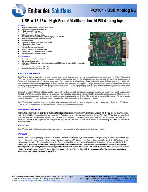
USB-AI16-16A - High Speed Multifunction 16-Bit Analog Input FEATURES• High-speed USB 2.0 device, sampling rate to 500kHz• All functions fully software configurable• 16-bit resolution A/D converter• 16 single-ended or 8 differential inputs• Eight input ranges, unipolar or bipolar• Real-time hardware auto-calibration and oversampling for accurate data• Unique channel-by-channel programmable gains• Data buffer for A/D• Synchronous, asynchronous, timed trigger modes• 16 high-current digital I/O lines• 16-bit programmable counter/timer• Alternate embedded USB connector• USB/104 form-factor for embedded OEM’s• Small (4" x 4" x 1.25") rugged industrial enclosure• All required power drawn from USB portFACTORY OPTIONS• External power for high current capabilities• DIN rail mounting provision• OEM (board only) version with PC/104 mounting holes and PCB footprint for added flexibility in embeddedapplications• Current ranges (4-20mA, 10-50mA) S.E. or Diff• Extended Temperature Operation -40 to +85°CFUNCTIONAL DESCRIPTIONThe USB-AI16-16A is an ideal solution for adding portable, easy-to-install high-speed analog and digital I/O capabilities to any computer with a USB port. The unit is a USB 2.0 high-speed device, offering the highest speed currently available with the USB bus. The USB-AI16-16A is a 16-bit resolution A/D board capable of speeds up to 500kHz for its 16 single-ended or 8 differential analog inputs. Each channel can be independently software configured to accept 8 different input ranges. Additionally, each channel includes its own analog ground pin on the I/O connector which is helpful in reducing noise. A unique, real-time internal calibration system allows the card to continually compensate for offset/gain errors giving a more accurate reading. The unit is plug-and-play allowing a quick connection whenever you need additional I/O on the convenience of a USB port.This small, compact, multifunction I/O board provides the user with everything needed to start acquiring, measuring, analyzing and monitoring in a variety of applications. The USB-AI16-16A data acquisition board can be used in many current real-world applications such as embedded equipment monitoring, precision PC-based and port-able environmental measurements, and mobile data acquisition. Additional features include 16 digital I/O lines and a programmable 16-bit counter. The counter can be configured in a variety of modes and has the ability to use external signals to trigger and control the scanning of its inputs.The USB-AI16-16A is designed to be used in rugged industrial environments but is small enough to fit nicely onto any desk or testing station. The board is PC/104 sized (3.550 by 3.775 inches) and ships inside a steel powder-coated enclosure with an anti-skid bottom.OEM USB/104 FORM FACTORThe OEM (board only) version is perfect for a variety of embedded applications. What makes the OEM option unique is that its PCB size and mounting holes match the PC/104 form factor (without the bus connections). This allows our rugged digital board to be added to any PCI-104 or PC/104 stack by connecting it to a simple USB port usually included on-board with embedded CPU form factors such as EBX, EPIC, and PC/104. This is especially important since many newer CPU chipsets do not support ISA and have plenty of USB ports. The USB-AI16-16A OEM board can also be installed using standoffs inside other enclo-sures or systems.ACCESSORIESThe USB-AI16-16A is available with optional cable assemblies and screw terminal boards for easy-to-use, out of the box connectivity.SOFTWAREThe USB-AI16-16A is plug-and-play which allows quick connect or disconnect whenever you need additional I/O on your USB port. The module utilizes a high-speed custom function driver optimized for a maximum data throughput that is 50-100 times faster than the USB human interface device (HID) driver used by many competing products. This approach maximizes the full functionality of the hardware along with capitalizing the advantage of high-speed USB 2.0. The USB-AI16-16A is supported for use in most USB supported operating systems and includes a free Linux and Windows 98se/Me/2000/XP/2003 compatible software package. This package contains sample programs and source code in Visual Basic, Delphi, C++ Builder, and Visual C++ for Windows. Also incorpo-rated is a graphical setup program in Windows. Third party support includes a Windows standard DLL interface usable from the most popular application pro-grams. Embedded OS support include Windows XPe.BLOCK DIAGRAMAnalog InputsADC TypeSuccessive approximation Sampling rateUSB-AI16-16A 500Ksamples/sec (maximum aggregate) USB-AI16-16E 250Ksamples/sec (maximum aggregate) Resolution16-bit Number of channels 16 single-ended or 8 differential (software selectable) Bipolar ranges ±1V, ±2V, ±5V, ±10V (software selectable) Unipolar ranges 0-1V, 0-2V, 0-5V, 0-10V (software selectable) 4-20mA or 10-50mA Factory installed (optional) Board CalibrationVREF LOW: AGND VREF HIGH: 9.90V ± 0.0299V System Calibration Program provided to calibrate entire system Calibration Hardware USB-AI16-16A Calibrated real-time output for offset/gain errors USB-AI16-16E NONE Input impedance 1M A/D Start Sources Software Start, Timer Start, and External Start Trigger (rising or falling edge; software selectable) A/D Start Enable Externally supplied (pulled-up; active-high ) A/D Start Types Single Channel or Scan (software selectable) Channel Oversamp0-255 consecutive samples/channel Over volt protection -40 to +55V Crosstalk No crosstalk present below 400KHz -60dB @ 500KHzDigital I/OLines 16 inputs or outputs in groups of 8 (pulled-up) Input voltage Logic low: 0V(min) to 0.8V(max) Logic high: 2V(min) to 5V(max) Input current ±20:A (max) Output voltage Logic low: 0V(min) to 0.55V(max) Logic high: 2V(min) to 5V(max) Output current Logic low: 64mA(max) sink Logic high: 32mA(max) sourceCounter/TimerAvailable Counters Counter 0 Type: 82C54 programmable interval counter Input Frequency 10MHz (max) Counter size 16-bit Clock Internal 10MHz or Externally supplied (software selectable; pulled-up) Clock Period 100ns (min) Clock Pulse Width High 30ns (min) Clock Pulse Width Low 40ns (min) Gate Externally supplied (pulled-up; active-high) OutputExternal (pulled-up )SpecificationsInput/OutputVoltage/Current Same as Digital I/OEnvironmentalOperating Temperature 0º to +70ºC, optional -40º to +85ºC Storage Temperature-40º to +105ºC Humidity 5% to 90% RH, non-condensing Board Dimensions PC/104 format, 3.550” by 3.775” and mounting holes Power required +5V at 330mA typicalThe following items are included with your shipment• Board installed in labeled enclosure • 6’ USB cable• Software Master CD (PDF user manual installed with product package) • Printed USB I/O Quick-Start GuideOrdering GuideUSB-AI16-16A Advanced version, 16-Bit, 500kHz, with auto calibration USB-AI12-16EStandard version, 16-Bit, 250kHz, with software calibrationModel Options-PExternal AC/DC adapter (power jack/regulator installed) -OEM Board only (no enclosure) -DIN DIN rail mounting provision-T Extended Temperature Operation (-40º to +85ºC) -S0x “x” = special number designator - 4-20mA or 10-50mA inputs- 16 current inputs when factory configured as single-ended - 8 current inputs when factory configured as differential- DIO lines can be configured with pull down resistorsAccessoriesSTB-68Screw terminal board C68PS18L 68-Pin SCSI 18" shielded cable MP104-DIN DIN rail mounting provision CUSB-OTG-6 6' USB Cable with Type A to mini type OTG connector for embedded applications。
16路隔离语音控制器说明书 V1.1 (型号:YMG16) 秦皇岛千目电子有限公司
16路隔离语音控制器说明书V1.1(型号:YMG16)秦皇岛千目电子有限公司电话:************传真:************/1.产品特性 (2)2.产品图片、接口介绍 (2)2.1产品外形和接口图片 (2)2.2接口介绍 (3)2.3产品尺寸图 (3)3.音频信息下载 (4)3.1准备音频文件 (4)3.1.1软件合成音频文件 (4)3.1.2音频文件转换MP3格式 (4)3.1.3文件夹操作 (4)3.1.4文件名操作 (4)3.2下载语音 (4)3.2.1USB口连接PC (5)3.2.2产生U盘 (5)3.2.3格式化U盘 (5)3.2.4复制文件夹 (5)3.2.5下载完成 (5)4.控制方式 (6)4.1开关控制-16路开关 (6)4.1.1接线方式 (6)4.1.2控制方式 (6)4.2通讯控制-RS485 (7)4.2.1普通指令格式 (7)4.2.2Modbus-RTU指令格式 (8)4.3无线控制-遥控或发射模块(需扩展) (8)5.参数设置 (9)5.1硬件连接 (9)5.2参数设置 (9)5.2.1统一设置 (9)5.2.2分路设置 (10)5.3放音测试 (10)6.技术支持及联系方式 (10)语音控制器说明书(型号:YMG16)YMG16语音控制器是我公司推出的一款新型语音产品。
具有稳定可靠、可重复录音、宽电源电压、外部音量调节、支持背景音乐播放功能等特点。
可广泛应用于工业控制、安防报警、语音提示等场合。
1.产品特性●16路光耦隔离输入控制信号,可以控制16路语音播放。
●带485通讯,可以通过指令控制最多128段语音播放。
●485通讯支持Modbus-RTU协议,方便与其他设备进行组网调试。
●MP3格式语音存储,可播放提示语音和音乐,音质更好。
●TF格式存储卡,最大支持16G存储。
机器自带128M存储卡。
●USB口直接下载语音信息,操作方便。
●板载标准3.5MM音频孔,立体声输出,可外接音箱、音柱等功放设备。
SmartAVI DVN-16Pro 16-Port DVI-D KVM Switch with A

DVN ‐16ProUser ManualAccess and Control 16 Computerswith One USB keyboard, USB Mouse and DVI-D Monitor16-Port DVI-D KVM Switch with Audio and USB 2.0 SharingTABLE OF CONTENTSWHAT'S IN THE BOX? 2INTRODUCTION 3FEATURES 3APPLICATIONS 3TECHNICAL SPECIFICATIONS4 HARDWARE INSTALLATION5 FRONT PANEL CONTROL6 RS-232 COMMANDS7 HOTPLUG COMMANDS7 LIMITED WARRANTY STATEMENT 8Figure 2-1Figure 2-2WHAT'S IN THE BOX?DVN-16PROS1 DVN-16Pro, 16x1 DVI-D, USB 2.0, Audio Switch PS5VDC4A1 Power Supply/Adapter1 Quick Start Guide EN-DVN16P-EAR-P 2Mounting BracketsINTRODUCTIONThe DVN-16Pro is a dedicated multi-platform KVM switch capable of managing up to 16 different com-puters through a single DVI-D monitor, USB keyboard & mouse and a single set of speakers with USB 2.0 device sharing. The USB emulation technology utilized by the DVN-16Pro enables immediate hotkey source switching through a remote USB keyboard and mouse. The DVN-16Pro provides high resolution, up to 1920x1200 with zero pixel loss from TMDS signal correction.FEATURES∙ Supports Mac, PC, Linux and Sun DVI∙ Supports High Resolution1920x1200 60Hz WUXGA∙ Uses universal DVI Single Link connectors∙ Zero pixel loss with TMDS signal correction∙ Supports all USB 2.0 Devices (Flash Drives, Printers, Scanners, etc.)∙ Supports USB 2.0 keyboard and mouse∙ Balanced stereo audio output∙ Front panel buttons with LCD display∙ Full RS-232 control∙ Hotkey commands for quick channel selection∙ Complete keyboard emulation for error free booting∙ Independent (asynchronous) switching of KVM and peripheral USB/audio ports. Users can listen to audio from one computer while working on the other or scan a document and save in another com-puterSOURCE SWITCHING MADE EASYThe DVN-16Pro provides simplified control of up to 16 computers with DVI-D, audio, and USB 2.0 outputs. This dynamic KVM console can be controlled remotely from easily accessible keyboard hotkeys or RS-232 communication channel commands, as well as directly through the console’s easy to read front panel.EDID LEARNING & PROGRAMMINGDetection of DDC signals for all attached devices is effortless with DVN-16Pro due to its EDID learning and programming. This is vital in optimizing the resolution of the selected graphics card to properly dis-play on the remote monitor. Furthermore, the DDC learning feature continues to replicate the right EDID for the computer to enable the display card to effectively work when unused ports are not selected. FULL USB KEYBOARD AND MOUSE EMULATIONThe USB keyboard and mouse emulation utilized by DVN-16Pro provides accurate and quick source switching by means of keyboard hotkeys. The DVN-16Pro imitates the presence of a keyboard and mouse for every attached computer through its USB cable. This is essential as it simulates the existence of the keyboard and mouse to all the computers when switching out of the circuit.APPLICATIONS∙ Server Collocation∙ Digital Signage∙ Airports∙ Dealer Rooms∙ Control Rooms∙ Audio/Visual Presentations∙ Hotels/ResortsTECHNICAL SPECIFICATIONS FormatDVI-D Single Link Maximum Pixel Clock165 MHz Input Interface(16) DVI-D 29-pin (female) Output Interface(1) DVI-D 29-pin (female) ResolutionUp to 1920 x 1200 @60Hz DDC5 volts p-p (TTL) Input EqualizationAutomatic Input Cable LengthUp to 20 ft. Output Cable Length Up to 20 ft.Input Interface (16) 3.5 mm Stereo AudioOutput Interface (1) 3.5 mm Stereo AudioImpedance 600 Ohm Frequency Response 20 Hz to 20 kHzSignal Type USB 2.0, 1.1, and 1.0 w/ internal hubInput Interface (16) USB Type B (female)Output Interface (2) USB Type A (female) for keyboard and mouse emulation; (2) for USB 2.0 TransparentFront Panel Buttons and LCD DisplayRS-232Via Control @ 115200 bps Hotkeys Via KeyboardPowerExternal 100-240 VAC/ 5VDC4A @20W Dimensions17” W x 3.625” H x 7.5“ D Weight5.3 lbs. Common Mode Rejection at 60 dBNominal Level 0-1.0 VOperating Temp.32-131 °F (0-55 °C) Storage Temp.-4-185 °F (-20-85 °C) HumidityUp to 95% No Condensation Emulation Keyboard and MouseHARDWARE INSTALLATION1. Ensure that the power is disconnected from DVN-16Pro.2. Connect the DVI cables, USB cables (male-A to male-B), and audio cables from the computers to therespective ports on the DVN-16Pro.3. Optionally connect RS-232 for control functions.4. Connect the USB keyboard and mouse to the two USB ports labeled keyboard/mouse.5. Optionally connect USB peripherals (flash drives, printers, etc.) to the “USB 2.0 OUT” ports.6. Connect speakers to the Audio Out ports.7. Connect the display monitor to the OUT DVI connector on the DVN-16Pro.8. Power on the DVN-16Pro.Figure 5‐1FRONT PANEL CONTROLTo switch ports using the front panel, press either the Enter button for up or the Scroll button for down to select the port you would like to switch to. The selected port number will be indicated on the LED display.Pressing both the Scroll and Enter buttons simultaneously will display a menu on the LCD.Press the Scroll button to move between the selections and the Enter button to execute the selection. The selections are:Learn Screen: Learn EDID from connected monitor.Hot Plug: Resets a pin on the DVI connector causing the DVN-16Pro to re-learn the connected monitor’s EDID settings.Exit: Exits Menu.Figure 6‐1RS-232 COMMANDSThe DVN-16Pro may also be controlled via RS-232 commands. This feature requires that an RS-232 card is installed in your computer or a USB to RS-232 adapter. Check the RS-232 connections on your com-puter and the DVN-16Pro to determine if you need a male to male, female to female or male to female cable.Establish a connection to DVN-16Pro :1. Connect a straight-through RS-232 cable to the RS-232 connector on the PC.2. Connect the other end of the cable to the RS-232 port of the DVN-16Pro .3. Power on the device.If you need to identify the COM port used by your computer do the following:1. Click on the start button.2. Click on Control Panel.3. Click on Device Manager.4. Click on the arrow next to Ports (COM & LPT).You should see the name of your adapter and the COM port number in use.Setting up the Terminal Application:Run the terminal client of your choice such as HyperTerminal or PuTTY.Select the correct COM port on the PC.Use the following connection settings: 9600, N, 8, 1, no flow control.NOTE: PuTTY and other terminal software may not default to the settings above. If your RS-232 connec-tion seems un-responsive, cycling power to the DVN-16Pro will reset all values and boot up messages will be sent to your terminal display and verify the connection.HOTKEY COMMANDS The Hotkey command is a keyboard sequence used to trigger an action on the DVN-16Pro through the use of the keyboard connected on the USB port of the DVN-16Pro. To activate the hotkey sequence, press the CTRL key twice and then enter the desired hotkey command.Table 7-1 Switch all devices (KVM, USB 2.0, and Audio) [CTRL] [CTRL] m [port #] [ENTER]//m[port #] [ENTER] Switch KVM only[CTRL] [CTRL] c [port #] [ENTER] //c[port #] [ENTER] Switch audio only[CTRL] [CTRL] a [port #] [ENTER] //a[port #] [ENTER] Reset[CTRL] [CTRL] r //r Switch USB 2.0 only[CTRL] [CTRL] u [port #] [ENTER] //u [port #] [ENTER] Reload EDID (Toggle Hotplug pin)n/a //h [ENTER] Same as front panel up arrow button[CTRL] [CTRL] ↑ n/a Same as front panel down arrow button [CTRL] [CTRL] ↓n/aLIMITED WARRANTY STATEMENTA. Extent of limited warrantySmart‐AVI Technologies, Inc. warrants to the end‐user customers that the Smart‐AVI product specified above will be free from defects in materials and workmanship for the duration of 1 year, which duration begins on the date of purchase by the customer. Customer is responsible for maintaining proof of date of purchase.Smart‐AVI limited warranty covers only those defects which arise as a result of normal use of the product, and do not apply to any:a. Improper or inadequate maintenance or modificationsb. Operations outside product specificationsc. Mechanical abuse and exposure to severe conditionsIf Smart‐AVI receives, during applicable warranty period, a notice of defect, Smart‐AVI will at its discretion replace or repair defective product. If Smart‐AVI is unable to replace or repair defective product covered by the Smart‐AVI warranty within reasonable period of time, Smart‐AVI shall refund the cost of the product.Smart‐AVI shall have no obligation to repair, replace or refund unit until customer returns defective product to Smart‐AVI.Any replacement product could be new or like new, provided that it has functionality at least equal to that of the product being replaced.Smart‐AVI limited warranty is valid in any country where the covered product is distributed by Smart‐AVI.B. Limitations of warrantyTo the extant allowed by local law, neither Smart‐AVI nor its third party suppliers make any other warranty or condition of any kind whether expressed or implied with respect to the Smart‐AVI product, and specifically disclaim implied warranties or conditions of merchantability, satisfactory quality, and fitness for a particular purpose.C. Limitations of liabilityTo the extent allowed by local law the remedies provided in this warranty statement are the cus‐tomers sole and exclusive remedies.To the extant allowed by local law, except for the obligations specifically set forth in this warranty statement, in no event will Smart‐AVI or its third party suppliers be liable for direct, indirect, special, incidental, or con‐sequential damages whether based on contract, tort or any other legal theory and whether advised of the possibility of such damages.D. Local lawTo the extent that this warranty statement is inconsistent with local law, this warrantystatement shall be considered modified to be consistent with such law.NOTICEThe information contained in this document is subject to change without notice. SmartAVI makes no war‐ranty of any kind with regard to this material, including but not limited to, implied warranties of merchant‐ability and fitness for particular purpose. SmartAVI will not be liable for errors contained herein or for inci‐dental or consequential damages in connection with the furnishing, performance or use of this material. No part of this document may be photocopied, reproduced, or translated into another language without prior written consent from SmartAVI Technologies, Inc.20160825。
- 1、下载文档前请自行甄别文档内容的完整性,平台不提供额外的编辑、内容补充、找答案等附加服务。
- 2、"仅部分预览"的文档,不可在线预览部分如存在完整性等问题,可反馈申请退款(可完整预览的文档不适用该条件!)。
- 3、如文档侵犯您的权益,请联系客服反馈,我们会尽快为您处理(人工客服工作时间:9:00-18:30)。
M d Mounting torque
(M5)
2-2.5Nm (10-32 UNF)
18-22lb.in.Weight
35
g
Features
q Package with DCB ceramic base plate q Isolation voltage 3600 V~q Planar passivated chips
q Blocking voltage up to 1600 V q Low forward voltage drop
q Leads suitable for PC board soldering q
UL registered E 72873
Applications
q Supply for DC power equipment q
DC motor control
Advantages
q Easy to mount with two screws q Space and weight savings
q
Improved temperature and power cycling
Dimensions in mm (1 mm = 0.0394")
V RRM = 800-1600 V I dAVM = 21 A
Half Controlled
Single Phase Rectifier Bridge
Including Freewheeling Diode and Field Diodes
135
2
6
8
10
Symbol Test Conditions Characteristic Values
I R , I D V R = V RRM ; V D = V DRM T VJ = T VJM £5mA T VJ = 25°C
£0.3mA V T , V F
I T , I F = 45 A; T VJ = 25°C
£
2.55V V T0For power-loss calculations only (T VJ = 125°C) 1.0V r T 40m W V GT V D = 6 V;T VJ = 25°C £ 1.0V T VJ = -40°C £ 1.2V I GT
V D = 6 V;
T VJ = 25°C £65mA T VJ = -40°C £80mA T VJ = 125°C £50mA V GD T VJ = T VJM ;V D = 2/3 V DRM £0.2V I GD T VJ = T VJM ;
V D = 2/3 V DRM £5mA I L
I G = 0.3 A; t G
= 30 m s;T VJ = 25°C £
150mA di G /dt = 0.3 A/m s;
T VJ = -40°C £200mA T VJ = 125°C
£100mA I H T VJ = 25°C; V D = 6 V; R GK = ¥£100mA t gd T VJ = 25°C; V D = 0.5V DRM £2m s I G = 0.3 A; di G /dt = 0.3 A/m s
t q T VJ = 125°C, I T = 15 A, t P = 300 m s, V R = 100 V typ.
150m s Q r di/dt = -10 A/m s, dv/dt = 20 V/m s, V D = 2/3 V DRM 75m C R thJC per thyristor (diode); DC current 2.4K/W per module
0.6K/W R thJH
per thyristor (diode); DC current 3.0K/W per module
0.75
K/W
Symbol Test Conditions Maximum Ratings
I FAV T H = 85°C, per Diode 4A I FAVM per diode 4A I FRMS per diode 6A I FSM
T VJ = 45°C;t = 10 ms (50 Hz), sine 100A V R = 0 V t = 8.3 ms (60 Hz), sine 110A T VJ = T VJM t = 10 ms (50 Hz), sine 85A V R = 0 V
t = 8.3 ms (60 Hz), sine 94A I 2t
T VJ = 45°C t = 10 ms (50 Hz), sine 50A 2s V R = 0 V t = 8.3 ms (60 Hz), sine 50A 2s T VJ = T VJM t = 10 ms (50 Hz), sine 36A 2s V R = 0 V
t = 8.3 ms (60 Hz), sine 37A 2s I R V R = V RRM
T VJ = T VJM 1mA T VJ = 25°C
0.15mA V F I F = 21 A; T VJ = 25°C
1.83V V T0For power-loss calculations only (T VJ = 125°C)0.9V r T 50m W R thJC per diode; DC current 4.4K/W R thJH
per diode; DC current
5.2
K/W
Field Diodes
Data according to IEC 60747 and refer to a single thyristor/diode unless otherwise stated.x for resistive load
IXYS reserves the right to change limits, test conditions and dimensions.
Fig. 1Gate trigger range
Fig. 2Gate controlled delay time t gd
11010010000.11
10
I G
V G
mA
V 10
100
1000
110
100
1000µs t gd mA I G
750
1020304050
607001020304050607080900.00.51.01.52.02.53.03.5I F A P tot
W Z thJH Fig. 3Fig. 6Fig. 8。