利用PLC+变频器+触摸屏的水位控制
触摸屏与PLC构架下的水温PID控制【毕业作品】

BI YE SHE JI(20 届)触摸屏与PLC构架下的水温PID控制所在学院专业班级自动化学生姓名学号指导教师职称完成日期年月毕业设计(论文)任务书I、毕业设计(论文)题目:触摸屏与PLC架构下的水温PID控制II、毕业设计(论文)使用的原始资料(数据)及设计技术要求:1、英文翻译一篇2、学习PLC的使用,掌握程序的编写3、学习触摸屏与PLC的通讯连接方式4、熟悉PID算法III、毕业设计(论文)工作内容及完成时间:1、第1周—第3周查阅资料、翻译英文资料并撰写开题报告2、第4周—第7周熟悉相关软件开发环境和用户手册;3、第8周—第12周对必要的知识进行学习;4、第13周—第16周实现水温的PID控制5、第17周—18周总结,撰写论文并准备答辩Ⅳ、主要参考资料:1、樊军庆,张宝珍.温度控制理论的发展概况.工业炉,30(6):12-14,20082、齐剑玲,曾玉红.工控机在工业锅炉温度检测控制系统中的应用.微计算机信息,19(9):36-37,20033、毛忠国,杨超.从控制角度谈PLC、DCS及FCS三大系统的差异.宁夏电力,增刊 (2):103-105,20074、张爱筠,张琳琳,贺楠.温度控制系统的设计与市场研究.商业经济,2:57-58,20085、刘敏.浅谈DCS和PLC的区别.国外建材科技,29(4):113-115,2008触摸屏与PLC构架下的水温PID控制摘要:可编程控制器是一种自动控制装置,在当今应用非常广泛,它是通过传统的继电器控制技术与计算机技术和通讯技术融为一体,造就了它控制能力强、操作灵活方便、可靠性高、适宜长期连续工作等特点,非常适合温度控制的要求,然而温度控制系统在工业控制领域应用也非常广泛,比如钢铁厂、化工厂、火电厂等锅炉的温度控制系统,电焊机的温度控制系统等都可以应用其工作原理。
加热炉温度一般采用PID 调节进行控制的,随着PLC功能的应用在许多PLC控制器中都涉及到了PID 控制功能, 因此在逻辑控制与PID控制混合的应用场所中采用PLC控制是较为合理的。
PLC实验(水塔水位控制的模拟)

实验三水塔水位控制的模拟
在S23 S7-200模拟实验挂件(三)本实验。
一、实验目的
用PLC构成水塔水位自动控制系统,掌握定时器的使用方法。
二、实验内容
(1)当水池水位低于水池低水位界(S4为ON表示),阀Y打开进水(Y为ON)定时器开始定时;
(2)阀Y打开4秒后,如果S4还不为OFF,那么阀Y指示灯闪烁,表示阀Y 没有进水,出现故障;
(3)S3为ON后,阀Y关闭(Y为OFF)。
当S4为OFF时,且水塔水位低于水塔低水位界时S2为ON,电机M运转抽水。
当水塔水位高于水塔高水位界时电机M停止。
三、水塔水位控制的实验面板图
说明:面板中S1表示水塔的水位上限,S2表示水塔水位下限,S3表示水池水位上限,S4表示水池水位下限,M1为抽水电机,Y为水阀。
四、输入/输出接线列表
五、梯形图参考程序
六、实验注意事项
1、严格按照规定操作。
2、注意安全,不要触摸带电元器件,实验接线完成经指导老师检查后方可
送调试。
3、注意各设备送电顺序,实验完毕后关闭电源。
七、实验报告内容要求
1、实验名称
2、实验目的
3、实验装置介绍
4、实验原理及过程
5、实验过程及程序
6、实验结果及体会
/view/48dd70f90242a8956bece4f4.html /view/1a76d620aaea998fcc220ea9.html /view/3f28254bcf84b9d528ea7a34.html。
PLC和HMI实现系列水箱液位控制自动化说明书

AUTOMATION OF SERIES TANK LEVEL CONTROL USING PLC AND HMIThan Than Min1, Saw Kay Thwe Moe2, Hnin Thae Mon31 Than Than Min, Department of Electronic Engineering, Kyaukse, Myanmar2 Saw Kay Thwe Moe, Department of Electronic Engineering, Kyaukse, Myanmar3 Hnin Thae Mon, Department of Electronic Engineering, Kyaukse, MyanmarABSTRACTThe proposed system provides an analysis of the simulation and components required for the implementation of an automated level control system by the help of Programmable Logic Controller (PLC).Water level management using PLC is design to control the level of water and avoid wastage of water in the tank.This system has an automatic pumping system attach to it.The purpose of this paper is reducing time consumption and human resource consumption, increase product revenue and greater accessibility or more security.Also by using this paper the wastage of water occurred by overflowing of tanks can be avoided. The proposed model can effectively supervise level control in multiple tanks. Four level sensors were used to provide the level data to the PLC. PLC used this data to take the required decisions and thereby turning ON and OFF a pump. A manual switch was also provided to override the automatic system. The SIMATIC universal controller was used as the main decision making module. The system was implemented to create the required Human Machine Interface (HMI). Modifications can be made by using float sensors model which would effectively provide the correct level but cost would increase and vibration of the sensor might disrupt the result, our model effectively counters those short comings.In future by making some changes this project can be used in different industries related to fluids like petroleum industries or oil refineries for controlling the level of filling the tanks and avoid wastage. Keyword: - Automation, PLC, HMI, Tank-level Control1. IntroductionFig-1 Block Diagram of PLC SystemThe PLC is a device that was invented to replace the necessary sequential relay circuits for machine control. The user enters a program usually via software that gives the desired results. This control machine operationis typically stored in battery-backed up or nonvolatile memory. In our project we used SIEMENS PLC has effectively designed tank filling plant using PLC and HMI gives a proposed system that efficiently controls a cement factory using PLC. One of the most widely used control systems is Programmable Logic Controller (PLC). Its applications cover a wide range of industries from cigarette, automotive, petrochemical, paper, and even to the mining industry, for example, in the control of gas turbines and advanced industrial units of mining products. The ease of transitioning from the previous control systems (e.g., from mechanical relay-based control systems) and the ease of troubleshooting the system configurations are the two main factors driving the popularity of this PLC.PLC is a system that can manipulate, execute, and or monitor the state of the process at a very fast rate, on the basis of programmable data in an integral microprocessor-based system. PLC receives inputs and produces output electrical signals to control a system. Thus the controlled quantities of physics and chemistry, before being processed by the PLC, will be converted into electrical signals both analog and digital, which is the basic data. The formulation of the problem is to know how to enter and run ladder logic PLC program; it will explain how to connect PLC with an induction motor.2.HARDWARE IMPLEMENTATION2.1 System DesignLow LevelSensor(Upper Tank)High LevelSensor (Lower Tank)Low LevelSensor (Lower Tank)PLCMANUALSWITCHPUMPHMIClose InletValveHigh LevelSensor(Upper Tank)Fig -1 Overall Block DiagramThe storage Tank is to be filled by a Pump. The pump will automatically start when the water level of storage Tank reaches below Low Level and stop when the level reaches High Level. Dry run is checked by the Low Level sensor of the Tank. The implementation is divided into three parts:1. Sensor Positioning2. Ladder Programming3. HMI Designing2.2 A Sensor PositioningValveFig-2 Sensor PositioningTo measure level of both tanks, level sensors are installed. Use interlocking to control the inlet valve. Level sensors to the input module of the PLC, connect inlet valve with the output module of PLC. Four level sensors were used to sense presence of water at required levels. The sensors are LT_LL – Low Level Sensor lower tank (I 0.4), LT_HL – High Level Sensor lower tank (I 0.6), UT_LL – Low Level Sensor Upper tank (I 0.3), UT_HL – High Level Sensor Overhead tank (I 0.5) are placed.2.3 Ladder ProgrammingThe Ladder programming for the Siemens was done in Siemens sematic manager.The Ladder programming for the TIA Portal V13 software was done in TIA Portal V13 software. Figure shows a ladder logic programmed for controlling the water tank level which was simulated for two water tanks level control.Fig-3 S7-1200 PLC3. SOFTWARE IMPLEMENTATION3.1 Flow Chart of PLC programmingCheck InputStatusExecutiveProgramUpdate OutputStatusFig-3 Flow Chart of PLC programmingThe pump in the circuit supplies water to the tanks via pipelines. Level of both tanks is to be controlled. The solenoid valves open for the pump to start automatically when the water level in the water tanks reach a low level and close when the level of water reaches high level. The pump will not run when the level sensor in the borehole detects that the water in the borehole is at a low level or is empty. This was to ensure that the pump does not run dry. Provision was made for a manual Start/Stop switch which totally overrules the automated system in offline mode. The water tank filling system is has three main functions and these are, sensing (or detection), makingdecisions and implementation. The status of the whole system is communicated by the PLC to the HMI. During the implementation, three dual probe sensors were used. The function of the sensors was to detect the presence of water in the tank whiles the TIA Portal V13 software uses the readings of the sensors to make the required decision of starting or stopping the pump, and also opening or closing the solenoid valves. Finally the decision is implemented by the PLC through a relay switch. The TIA Portal V13 provides information on the current status of the system through the IM port to the computer which is accessible by the HMI. ((()))M0.1Start M0.2Stop Q0.1Master CoilQ0.1Master Coil Q0.1Master Coil Q0.2Inlet Valve Q0.2Inlet Valve Q0.3Close Inlet Valve Q0.3Close Inlet Valve M0.3LLST1M0.4LLST2M0.5LHST1M0.5LHST1Fig-5 Ladder Programming3.2 HMI DesigningThe Human Machine Interface is the means through which an operator or user can communicate with the system. The present status of the system is sent to the operator or user by means of a graphical user interface (GUI). The operator or user can interact with the system by turning ON or OFF various functions from the interface. We used tags for the communication of the PLC Ladder logic operation in the sematic manager with theHMI. The whole project is shown along with the sensor positions.4. TEST AND RESULTThe pump will start when the PLC is turned on for the first time presuming all the two Tanks are empty and there is no water flow from the storage tank. Figure 6 is a ladder logic program me and HMI panel for the start of the automation in filling the tank .Fig-6 Create the HMI Panel for Level Tanks ControlFig- 7 When Start button is press, the master coil is activeFig- 8 When Start button and Low Level switch is press, the master coil and inlet valve is active Now all the two tanks are full, the pump is stopped, the inlet valves is close.Fig-9 When Start button and High Level switches is press, the master coil and close inlet valve is activeFig-10 When Start button and Stop button is press, this process is stop5.ConclusionAn automated system of water tank filling at a water processing unit using a PLC system has been designed and implemented through simulation. The simulation clearly shows that the automation of the water tank filling will prevent, the incidence of tank overflow since water tank filling is automatically controlled, the incidence of pump overheating since the pump will not run dry, the stress associated with manual operation, the human dependent of the system.6. AcknowledgmentThe author would like to thank to their parents and their colleagues. The author has to express out appreciation to their candidate for hard working during the course of this research.7. REFERENCES[1]http://www. /plc-progra[2]/…..Tank[3]Siemens system Manual, 2014[4]Hao, L. and Ruilin, P. (2005). Application of Centralized PLC Automation Control in Painting Line of SteelPlant. Proceeding of the 4th Asian Conference on Industrial Automation and Robotics, Landmark Hotel, Thailand [5]Collins, K. (2007), PLC Programming For Industrial Automation, Exposure Publishing, Australia, pp. 140.。
基于PLC的变频器液位控制设计
基于PLC的变频器液位控制设计随着电力电子技术以及工业自动控制技术的发展,使得交流变频调速系统在工业电机拖动领域得到了广泛应用。
另外,由于PLC的功能强大、容易使用、高可靠性,常常被用来作为现场数据的采集和设备的控制。
本设计就是利用变频器和PLC实现水池水位的控制。
变频器技术是一门综合性的技术,它建立在控制技术、电子电力技术、微电子技术和计算机技术的基础上。
它与传统的交流拖动系统相比,利用变频器对交流电动机进行调速控制,有许多优点,如节电、容易实现对现有电动机的调速控制、可以实现大范围内的高效连续调速控制、实现速度的精确控制。
容易实现电动机的正反转切换,可以进行高额度的起停运转,可以进行电气制动,可以对电动机进行高速驱动。
完善的保护功能:变频器保护功能很强,在运行过程中能随时检测到各种故障,并显示故障类别(如电网瞬时电压降低,电网缺相,直流过电压,功率模块过热,电机短路等),并立即封锁输出电压。
这种“自我保护”的功能,不仅保护了变频器,还保护了电机不易损坏。
PLC特点:第一,可靠性高、抗干扰能力强,平均故障时间为几十万小时。
而且PLC采用了许多硬件和软件抗干扰措施。
第二,编程简单、使用方便目前大多数PLC采用继电器控制形式的梯形图编程方式,很容易被操作人员接受。
一些PLC还根据具体问题设计了如步进梯形指令等,进一步简化了编程。
第三,设计安装容易,维护工作量少。
第四,适用于恶劣的工业环境,采用封装的方式,适合于各种震动、腐蚀、有毒气体等的应用场合。
第五,与外部设备连接方便,采用统一接线方式的可拆装的活动端子排,提供不同的端子功能适合于多种电气规格。
第六,功能完善、通用性强、体积小、能耗低、。
基于PLC的变频器液位控制设计

结 构框 图 , 然后 在根据 工艺要 求 , 绘制 出各功 能单 元的详细功 能框 图。 4 3编 写程序 . 编写 程序就 是 根据设 计 出的 框 图逐 条地
编写控制 程序 , 这是整个 程序设计 工作的核心
部分 。 4 4 程 序测试和 调试 . 程序 测试和调试 不 同 , 软件测试 的 目的是 尽 可能 多地 发现软件 中的错误 , 软件调 试的任 务是 进一 步 诊 断和 改正 软 件 中的错 误 。 4 5 编 写程序说 明书 . 程序说 明书是对 程序的综 合说 明 , 是整个 程 序 设 计 工 作 的总 结 。 图 1 系统设计流 程 图。 是
维普资讯
2Q Q: Q!
Sc en a Tech ogY i ce nd nol Consu tng I i Her d al
工 业 技 术
基于 P C的变频器 液位控制设计 L
张 斌 ( 哈工ห้องสมุดไป่ตู้ 电子仪器 厂 )
摘 要: 随着 电力电子技术以及工业 自动控制技术的发展 , 得交流变频调 速系统在工业 电机 拖动领域得 到了广泛应用 。另外 , 使 由于 P C L 的功能 强大、容 易使 用、高可靠性 , 常常被用 来作为现场数据 的采集 和设 备的控制 。 本设计就是利 用变频 器和 PL C实现水 池水位的控
的选 用高性 能的 P C, 全能够 胜任 此功 能 。 L 完 系统 控制结构 如 图 l 示。 所 P C采集 传感 器 、监 控 电机及变 频器等 L 有关 的各类对象 的信息 。本 系统 中, 电机采 对 用一 台变 频 器来进 行频 率 的调节 控制 。采用 P C输 出 的模拟量 信号作 为变频 器的控 制端 L 输 入 信号 , 而 控制 电机 转 速大 小 , 从 并且 向 P LC反馈 自身 的工 作状 态信号 , 当发生 故障 时, 能够 向 P C 出报警信号 。由于变 频调速 L 发 是通 过改 变 电动机 定子 供 电频率 以改 变 同步 转速来 实现 的 , 故在调 速过 程 中从 高速到 低速 都可 以保 持 有 限的 转 差功 率 , 此具 有 高效 因 率 、宽范 围、高精 度的调速 性 能。
plc课程设计水位

plc课程设计水位一、教学目标本章节的教学目标为:知识目标:使学生掌握PLC的基本原理和应用,理解水位控制系统的组成和工作原理。
技能目标:培养学生能够运用PLC实现水位控制系统的设计和调试。
情感态度价值观目标:培养学生对自动化技术的兴趣和认识,提高学生解决实际问题的能力。
二、教学内容本章节的教学内容主要包括:1.PLC的基本原理和应用:PLC的组成部分,工作原理及其在水位控制系统中的应用。
2.水位控制系统的组成和工作原理:水位传感器的选型,执行机构的控制,以及PLC的程序设计。
3.PLC程序设计:根据水位控制要求,使用PLC进行程序设计,实现水位的自动控制。
三、教学方法本章节的教学方法采用:1.讲授法:讲解PLC的基本原理,水位控制系统的组成和工作原理。
2.案例分析法:分析实际的水位控制案例,引导学生理解并掌握PLC的应用。
3.实验法:学生动手进行PLC编程和实验,实际操作水位控制系统。
四、教学资源本章节的教学资源包括:1.教材:PLC相关教材,用于引导学生学习理论知识。
2.多媒体资料:视频、图片等资料,用于辅助讲解和展示水位控制系统的工作原理。
3.实验设备:PLC实验装置,用于学生动手实践,加深对知识的理解。
五、教学评估本章节的教学评估主要包括:1.平时表现:评估学生在课堂上的参与程度,提问和回答问题的表现,以及小组合作的表现。
2.作业:评估学生完成作业的质量,包括PLC程序的设计和调试,以及相关练习题的解答。
3.考试:设计考试题目,评估学生对PLC原理和水位控制系统知识的掌握程度,以及运用PLC解决实际问题的能力。
评估方式应客观、公正,全面反映学生的学习成果。
教师应及时给予反馈,帮助学生提高。
六、教学安排本章节的教学安排如下:1.教学进度:按照教材和教学大纲,合理安排每个知识点的讲解和实践操作。
2.教学时间:充分利用课堂时间,保证理论讲解和实践操作的平衡。
3.教学地点:课堂讲解在教室进行,实践操作在实验室进行。
《PLC》水塔水位的模拟控制实验
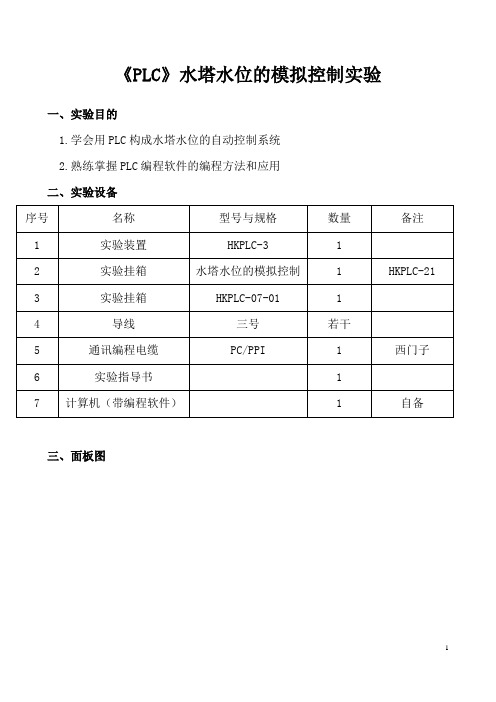
《PLC》水塔水位的模拟控制实验一、实验目的1.学会用PLC构成水塔水位的自动控制系统2.熟练掌握PLC编程软件的编程方法和应用二、实验设备三、面板图1四、控制要求当水池水位低于水池低水位界(SB4为ON表示),阀L2打开进水(L2为ON)定时器开始定时,4秒后,如果SB4还不为OFF,那么阀L2指示灯闪烁,表示阀L2没有进水,出现故障,SB3为ON后,阀L2关闭(L2为OFF)。
当SB4为OFF时,且水塔水位低于水塔低水位界时SB2为ON,电机L1运转抽水。
当水塔水位高于水塔水位界时电机L1停止。
五、端口分配表2六、操作步骤1、按照I/O端口分配表或接线图完成PLC与实验模块之间的接线,将PLC的DI 输入端中的1M、2M公共端接到公共端的M端,将PLC的DO输出端中的1L、2L、3L公共端接到公共端的L+端,实验挂箱的COM端接到公共端的M端。
+24V接到公共端的L+端,认真检查,确保正确无误。
2、打开示例程序或用户自己编写的控制程序,进行编译,有错误时根据提示信息修改,直至无误,用PC/PPI通讯编程电缆连接计算机串口与PLC通讯口,打开PLC主机电源开关,下载程序至PLC中,下载完毕后将PLC的“RUN/STOP”开关拨至“RUN”状态。
3、按下按钮SB4为ON后,阀L2打开进水(L2为ON)。
定时器开始定时,4秒后,如果SB4还不为OFF,那么阀L2指示灯闪烁,表示阀L2没有进水,出现故障。
4、按下按钮SB3为ON后,阀L2关闭(L2为OFF)。
5、松开按钮SB4(SB4为OFF)时,按下SB2(SB2为ON)即水塔水位低于水塔低水位界时,电机L1运转抽水。
6、按下按钮L1电机L1停止。
七、实验总结1.了解并掌握水塔水位模拟控制的的工作原理。
2.能熟练运用编制和调试PLC程序的方法3。
变频器、PLC在恒液位控制中的应用
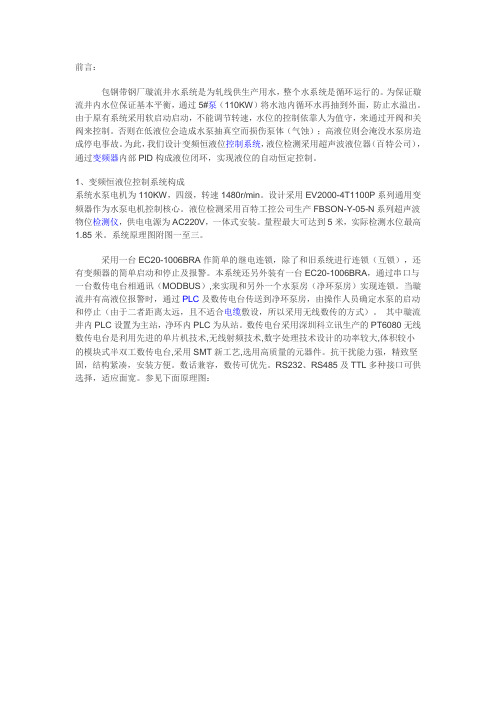
前言:包钢带钢厂璇流井水系统是为轧线供生产用水,整个水系统是循环运行的。
为保证璇流井内水位保证基本平衡,通过5#泵(110KW)将水池内循环水再抽到外面,防止水溢出。
由于原有系统采用软启动启动,不能调节转速,水位的控制依靠人为值守,来通过开阀和关阀来控制。
否则在低液位会造成水泵抽真空而损伤泵体(气蚀);高液位则会淹没水泵房造成停电事故。
为此,我们设计变频恒液位控制系统,液位检测采用超声波液位器(百特公司),通过变频器内部PID构成液位闭环,实现液位的自动恒定控制。
1、变频恒液位控制系统构成系统水泵电机为110KW,四级,转速1480r/min。
设计采用EV2000-4T1100P系列通用变频器作为水泵电机控制核心。
液位检测采用百特工控公司生产FBSON-Y-05-N系列超声波物位检测仪,供电电源为AC220V,一体式安装。
量程最大可达到5米,实际检测水位最高1.85米。
系统原理图附图一至三。
采用一台EC20-1006BRA作简单的继电连锁,除了和旧系统进行连锁(互锁),还有变频器的简单启动和停止及报警。
本系统还另外装有一台EC20-1006BRA,通过串口与一台数传电台相通讯(MODBUS),来实现和另外一个水泵房(净环泵房)实现连锁。
当璇流井有高液位报警时,通过PLC及数传电台传送到净环泵房,由操作人员确定水泵的启动和停止(由于二者距离太远,且不适合电缆敷设,所以采用无线数传的方式)。
其中璇流井内PLC设置为主站,净环内PLC为从站。
数传电台采用深圳科立讯生产的PT6080无线数传电台是利用先进的单片机技术,无线射频技术,数字处理技术设计的功率较大,体积较小的模块式半双工数传电台,采用SMT新工艺,选用高质量的元器件。
抗干扰能力强,精致坚固,结构紧凑,安装方便。
数话兼容,数传可优先。
RS232、RS485及TTL多种接口可供选择,适应面宽。
参见下面原理图:2、变频恒液位控制参数及工作原理:2.1 EV2000 通用技术规格:点击看原图输入额定电压;频率三相,380V~440V;50Hz/60Hz允许电压工作范围电压:320V~460V;电压失衡率:<3%;频率:±5%输出额定电压380V频率0Hz~650Hz过载能力G型:150%额定电流1分钟,200%额定电流0.5秒;P型:110%额定电流1分钟;150%额定电流1秒主要控制性调制方式磁通矢量PWM调制调速范围1:100起动转矩0.50Hz时180%额定转矩运行转速稳态精度≤±0.5%额定同步转速能频率精度数字设定:最高频率×±0.01%;模拟设定:最高频率×±0.2%频率分辨率数字设定:0.01Hz;模拟设定:最高频率×0.1%转矩提升自动转矩提升,手动转矩提升0.1%~30.0%V/F曲线四种方式:1种用户设定V/F曲线方式和3种降转矩特性曲线方式(2.0次幂、1.7次幂、1.2次幂)加减速曲线三种方式:直线加减速、S曲线加减速及自动加减速方式;四种加减速时间,时间单位(分/秒)可选,最长60小时直流制动直流制动开始频率:0.20~60.00Hz;制动时间:0.0~30.0秒;制动电流:G型:0.0~100.0%P型:0.0~80.0%点动点动频率范围:0.20Hz~50.00Hz;点动加减速时间0.1~60.0秒可设,点动间隔时间可设多段速运行通过内置PLC或控制端子实现多段速运行内置PI 可方便地构成闭环控制系统自动节能运行根据负载情况,自动优化V/F曲线,实现节能运行自动电压调整(AVR)当电网电压变化时,能自动保持输出电压恒定自动限流对运行期间电流自动限制,防止频繁过流故障跳闸自动载波调整根据负载特性,自动调整载波频率;可选客户化功能纺织摆频纺织摆频控制,可实现中心频率可调的摆频功能定长控制到达设定长度后变频器停机下垂控制适用于多台变频器驱动同一负载的场合音调调节调节电机运行时的音调瞬停不停机控制瞬时掉电时,通过母线电压控制,实现不间断运行捆绑功能运行命令通道与频率给定通道可以任意捆绑,同步切换运行功能运行命令通道操作面板给定、控制端子给定、串行口给定,可通过多种方式切换频率给定通道数字给定、模拟电压给定、模拟电流给定、脉冲给定、串行口给定,可通过多种方式随时切换辅助频率给定实现灵活的辅助频率微调、频率合成脉冲输出端子0~50kHz的脉冲方波信号输出,可实现设定频率、输出频率等物理量的输出模拟输出端子2路模拟信号输出,分别可选0/4~20mA或0/2~10V,可实现设定频率、输出频率等物理量的输出2.2为实现璇流井内恒液位控制,我们采用给定电位计作为液位给定,反馈采用超声波液位仪(变送输出4-20MA)。
- 1、下载文档前请自行甄别文档内容的完整性,平台不提供额外的编辑、内容补充、找答案等附加服务。
- 2、"仅部分预览"的文档,不可在线预览部分如存在完整性等问题,可反馈申请退款(可完整预览的文档不适用该条件!)。
- 3、如文档侵犯您的权益,请联系客服反馈,我们会尽快为您处理(人工客服工作时间:9:00-18:30)。
S7-200 PLC、变频器与触摸屏综合应用
SIEMENS
2、控制思路 、
因为液位高度与水箱底部的水压成正比,故可用一个压力传 感器来检测水箱底部压力,从而确定液位高度。要控制水位恒定, 需用PID算法对水位进行自动调节。把压力传感器检测到的水位信号 4~20mA送入至PLC中,在PLC中对设定值与检测值的偏差进行PID 运算,运算结果输出去调节水泵电机的转速,从而调节进水量。 水泵电机的转速可由变频器来进行调速。
S7-200 PLC、变频器与触摸屏综合应用
SIEMENS
3、元件选型 、
(1)PLC及其模块选型。PLC可选用S7-200 CPU224,为了能接 收压力传感器的模拟量信号和调节水泵电机转速,特选择一块 EM235的模拟量输入输出模块。 (2)变频器选型。为了能调节水泵电机转速从而调节进水量,特 选择西门子G110的变频器。 (3)触摸屏选型。为了能对水位值进行设定其对系统运行状态的 监控,特选用西门子人机界面TP170B触摸屏。 (4)水箱对象设备, 如下图所示。
S7-200 PLC、变频器与触摸屏综合应用
SIEMENS
S7-200 PLC、变频器与触摸屏综合应用
SIEMENS
二、EM235模块 模块 1、EM235的端子与接线 、 的端子与接线
S7-200 PLC、变频器与触摸屏综合应用
SIEMENS
2、DIP设定开关 、 设定开关
S7-200 PLC、变频器与触摸屏综合应用
S7-200 PLC、变频器与触摸屏综合应用
SIEMENS
(2)电路图
S7-200 PLC、变频器与触摸屏综合应用
SIEMENS
2、变频器参数设置 、
S7-200 PLC、变频器与触摸屏综合应用
SIEMENS
3、PLC编程 、 编程
S7-200 PLC、变频器与触摸屏综合应用
SIEMENS
S7-200 PLC、变频器与触摸屏综合应用
SIEMENS
S7-200 PLC、变频器与触摸屏综合应用
SIEMENS
3、EM235的技术规范 、 的技术规范
S7-200 PLC、变频器与触摸屏综合应用
SIEMENS
三、项目实现 1、PLC的I/O分配及电路图 、 的 分配及电路图
(1)PLC的I/O分配 启动按钮,I0.0;停止按钮,I0.1; Q0.0,控制水泵电机运行。
S7-200 PLC、变频器与触摸屏综合应用
SIEMENS
一、项目描述 1、项目控制要求 、
有一水箱可向外部用户供水,用户用水量不稳定,有时大有时少。水 箱进水可由水泵泵入,现需对水箱中水位进行恒液位控制,并可在0~ 200mm(最大值数据可根据水箱高度确定)范围内进行调节。如设定 水箱水位值为100mm时,则不管水箱的出水量如何,调节进水量,都 要求水箱水位能保持在100mm位置,如出水量少,则要控制进水量也 少,如出水量大,则要控制进水量也大。
S7-200 PLC、变频器与触摸0 PLC、变频器与触摸屏综合应用 、
多媒体教学光盘
S7-200 PLC、变频器与触摸屏综合应用
SIEMENS
第3讲 基于 讲 基于PLC、变频器、触摸屏的水位控制 、变频器、
一、项目描述 二、EM235模块 模块 三、项目实现 四、触摸屏监控
SIEMENS
S7-200 PLC、变频器与触摸屏综合应用
SIEMENS
四、触摸屏监控