AWM01A调试使用说明书
Micromega IA系列集成放大器操作手册说明书

OPERATING MANUALDear Customer,Thank you for purchasing one of the 3 Micromega Integrated amplifiers: IA-60, IA-100 or IA-180. These players are mainly different by their output power. This manual is then common for the 3 models.This unit provides ease of use and sonics of the highest quality. Please pay close attention to this instruction manual, and read it fully before attempting to operate. It is designed to ensure you maximise your pleasure of CD player and familiarise you with its many unique functions.CHECKINGCheck that the carton has no damage. Should you have any doubt about its condition, please do not hesitate to contact your dealer. UNPACKINGVery carefully remove the unit from the box, taking care to preserve all the packing material. It is good practice to put the carton and its contents into an outer plastic bag and deposit it somewhere safe and dry. In the unlikely event that your unit needs to be sent back to either your dealer or distributor, it must be sent in the original packing material. Failure to observe this will invalidate your warranty.ACCESSORIESUpon opening the carton you should find the following:-Mains Lead.MAINS VOLTAGE- Check that the mains voltage indicated on both the carton and the rear of the unit correspond to the local power supply- If you are in any doubt, consult your dealer.INSTALLATIONIn order to obtain the maximum performance of A60, it is important to follow the installation instructions.Wherever possible, we recommend that your amplifier is installed in an audio rack or other suitable furniture that provides sufficient ventilation.WARNING!If for aesthetic or ease of use reasons, you choose to stack the units, it is imperative that you place your amplifier on the top. Never place any unit on top of your amplifier. We recommend that you provide a space of at least 30cm above your amplifier in order to ensure adequate ventilation.CONNECTIONSHaving verified that the mains voltage indicated on the rear of the unit corresponds to the local power supply mains voltage and that the ON/OFF switch is on OFF position, connect the mains leads provided to the rear the unit and to the wall socket.Connect the Stereo Interconnect cables from the rear of all your sources to the corresponding inputs on your amplifier.Connect your loudspeaker cables between your amplifier and your loudspeakers paying attention to polarity.The very high quality speaker terminals accept different type of connections like bananas, or stripped up to 10mm² speaker wires. It is important to use quality speaker cable to get the maximum out of your amplifier. POWER UPYou may now turn on your amplifier by switching the ON/OFF switch located at the back of the unit.The display indicates the model of your amplifier:The display indicates:- On the left side the selected source.- On the right side the volume level.- In some cases the status of the unit (Balance, Headphone…). SELECTION (< INPUT SELECT >)The selection of inputs is made via the < INPUT SELECT >keys.- In order to select your choice of input use successive depressions of the key.The display will indicate the name of the selected source from the following list: PHO – AN1 – AN2 – AN3 – AN4 – iPod.VOLUMEThe setup of volume is achieved with the rotary control located in the centre of the front panel. The display will indicate a level between -80dB and 0 dB.Note: The rotary control allows access to different speeds of volume adjustment. If you turn slowly it will increment in single steps. Fast rotation increases the speed of the steps. This will allow you to move to the desired volume with great ease.LISTENING TO HEADPHONES (HEADPHONE)The headphone socket is located on the front panel of the unit. The headphone volume setting is independent of the loudspeaker volume. - Press the HEADPHONE key. The display will indicate:PRE-OUT OUTPUTSYour amplifier is fitted with PRE-OUT outputs to allow you to use an external power amplifier.2.1 MODEYour amplifier is equipped with a SUB-OUT output. You can connect an active subwoofer to this output. The level of this output is set by the main volume control of the unit.If you have an audio-video processor like AP-180, a SUB-IN input is available just Parity bit : None Stop bits : 1 Flow control: NoneYou will find complete instructions concerning this interface in the separate RS232 manual.AUDIS sarl. 13-15, rue du 8 mai 1945, ZA de la Haie Griselle, 94470 Boissy Saint Léger FRANCE TEL: +33 (0)1 4382 8860 - FAX: +33 (0)1 4382 6129 - INTERNET: TECHNICAL CHARACTERISTICS (SW ≥1.31) IA-XXXAudio CharacteristicsPower (IA-60 / 4Ω) …………………………….……………………………………………………………………………………………….……..…. 2 x 60 W Power (IA-100 / 4Ω) ………………………………………………………………………………………………………………………………….…. 2 x 100 W Power (IA-180 / 4Ω) ………………………………………………………………………………………………………………………………....…. 2 x 180 W Output Impedance ……………………………………………………………………………………………………………………….…..……. 0.02 Ω / 1 kHz Power Bandwidth (30 W / 4Ω / -3dB)………………………………………………………………………………………………….……….. 10 Hz - 100kHz Input Sensitivity /Impedance :AN1, AN2, AN3, AN4, iPod.………………………………………………………………………………………………….………...…… 280 mV / 47 k Ω PHONO …………………………….................................................................................................................................................... 18 mV / 47 k Ω Impedance / Gain Tape Output ………..................................................................................................................................................... 600 Ω / -6dB Distortion THD (20 Hz / 20 kHz) ……..................................................................................................................................…...................…. < 0.02 % Signal to Noise Ratio ……………………...................................................................................................................................................……. > 90 dBPower SupplyPower consumption (IA60)………………………………………………………………………………………………………….………………………. 150 W Power consumption (IA100)…………………………………………………………………………………………………………………..….…………. 220 W Power consumption (IA180)…………………………………………………………………………………………………………………..……….……. 320 WDimensions : (W x D x H mm) ………………………………………………………………………………………………….…………..430 x 300 x 70Weight (IA60)………………………………………………………………………………………………………………..………………………...…… 7.0 kg (IA100)……………………………………………………………………………………………………………………..…….………………… 8.0 kg (IA180)……………………………………………………………………………………………………………..………………….…………… 8.0 kgWARRANTYThis warranty will start from the date of purchase of the Micromega product.Statutory warranty regulations apply in the country where the Micromega product was purchased. In case ofcomplaints please contact the dealer who supplied your Micromega product.WARNING: Warranty will be nulled if the unit is not shipped back in its original packing or if the serial number has been modified or erased.Warranty Certificate Dealer's StampDate of PurchaseSerial Number。
PMC-651F馈线保护测控装置用户说明书_V2.0_130827
(版权所有,翻版必究)
PMC-651F 馈线保护测控装置用户说明书 版本 V2.0
目
1
录
装置简介 .............................................................................................................................................. 1 1.1 概述.................................................................................................................................................. 1 1.2 产品特点 .......................................................................................................................................... 1 1.3 基本功能 .......................................................................................................................................... 1 2 技术指标 ..................................................................................................................................
电磁配量泵GMXa操作说明书

电磁配量泵gamma/ X, GMXa操作说明书原版操作说明书 (2006/42/EC)零部件号 984566BA G 007 03/19 ZH请首先完整阅读使用说明书。
• 请勿丢弃说明书。
因安装或操作失误而造成的损失,由运营商承担。
最新版本的操作说明书可从我们的主页下载。
请阅读下列补充说明!之后您将能更好地使用操作说明书。
文中特别强调:n 列举操作指导ð操作指导的结果Ä “指明产品识别码和序列号” 第 2 页:指向本章中相关内容的链节- 参见 ...:指向本文档中相关内容或指向其它文档的参考[按键]“菜单级 1 è 菜单级 2 è 菜单级 ...”:菜单路径“软件界面文本” 信息说明书中给出了设备正确操作或易于您操作的重要信息。
安全提示安全提示用图标标识 - 参见“安全章节”。
在咨询或订购备件时,请务必指明铭牌上或菜单的“设置/菜单è 信息”中所注明的产品识别码和序列号。
由此可以明确识别设备型号和材料类型。
补充说明插图 1: 请阅读!指明产品识别码和序列号补充说明2目录目录1产品识别码 (6)2关于此泵 (9)3安全说明章节 (10)4储存、运输和拆包 (14)5设备概览和控制元件 (15)5.1 设备概览 (15)5.2 控制元件 (16)5.2.1 控制元件 (16)5.2.2 按键功能 (20)6功能说明 (21)6.1 输送单元 (21)6.2 驱动单元 (21)6.3 计量功率 (23)6.4 自动排气 (23)6.5 运行模式 (23)6.6 功能 (24)6.7 继电器(选件) (24)6.8 LED 指示灯 (25)6.9 运行模式、功能和故障状态的等级 (25)7装配 (26)8液压安装 (28)8.1 安装软管管路 (29)8.1.1 无排气装置的计量泵的安装 (29)8.1.2 带排气装置的计量泵的安装 (32)8.1.3 带自动排气装置的计量泵的安装(SEK 型号) (32)8.2 基本安装提示 (34)9电气安装 (35)9.1 连接电源电压 - 电源电压 (36)9.2 插口描述 (37)9.2.1 “外部控制”插口 (37)9.2.2 “液位开关”插口 (38)9.2.3 “计量监控”插口 (39)9.2.4 “隔膜破裂传感器”插口 (39)9.2.5 继电器 (40)10设置的基本信息 (43)10.1 控制系统设置基本信息 (43)10.2 检查可设置的参数 (45)10.3 切换到设置模式 (45)11设置/“菜单” (46)11.1 “信息” (46)11.2 “设置” (46)11.2.1 “运行模式” (47)11.2.2 “自动控制” (51)11.2.3 “冲程长度” (51)11.2.4 计量 (52)11.2.5 浓度 (56)11.2.6 校准 (61)11.2.7 系统 (63)3目录11.2.8 输入端/输出端 (65)11.2.9 排气 (69)11.2.10 “吸入时间” (71)11.2.11 “设置系统时间” (71)11.2.12 “日期” (71)11.3 计时器 (71)11.3.1 激活/禁用 (72)11.3.2 设置计时器 (72)11.3.3 全部删除 (78)11.3.4 示例 (78)11.3.5 计时器提示 (80)11.3.6 典型的缺陷 - 计时器功能故障 (80)11.3.7 所选功能的简要解释 (80)11.4 “服务” (85)11.4.1 “访问保护” (85)11.4.2 “密码 ” (85)11.4.3 “删除计数器” (86)11.4.4 “错误日志” (86)11.4.5 “更换隔膜” (86)11.4.6 “显示屏” (87)11.4.7 “出厂设置” (87)11.4.8 隔膜部件编号:XXXXXXX (87)11.4.9 备件组件编号:XXXXXXX (87)11.5 “语言” (Language) (87)12操作 (88)12.1 手动操作 (88)13维护 (90)14维修 (92)14.1 更换计量膜 (93)14.2 清洁隔膜破裂传感器 (95)14.3 清洁阀门 (95)15故障排除 (96)15.1 无错误信息的故障 (96)15.2 带错误信息的故障 (97)15.2.1 LCD 屏幕中的故障信息 (97)15.2.2 LCD 屏幕中的警告信息 (98)15.2.3 所有其它故障 (99)15.3 日志 (99)15.3.1 日志中的故障信息 (99)15.3.2 日志中的警告信息 (100)15.3.3 日志中的事件信息 (100)15.3.4 日志记录 - 详细视图 (101)16停用和废弃处理 (102)17技术数据 (104)17.1 功率参数 (104)17.2 精度 (105)17.2.1 标准输送单元 (105)17.2.2 自动排气式输送单元 (105)17.3 黏度 (105)17.4 材料参数 (106)4目录17.5 电气数据 (106)17.6 温度 (106)17.7 气候 (107)17.8 防护等级和安全要求 (107)17.9 兼容性 (107)17.10 装运重量 (108)17.11 声压级 (108)17.12 连续式吸液枪 (108)18分解系统图和订购信息 (110)18.1 分解系统图 (110)18.2 订购信息 (150)19尺寸图 (151)20计量流量设置图表 (160)21欧盟认证符合性声明 (163)22认证 (164)23gamma/ X 操作/设置概览 (165)24总操作菜单 gamma/ X (167)25常规显示和辅助显示 (173)26加装继电器的安装说明书 (175)27索引 (177)5产品识别码1 产品识别码6产品识别码7产品识别码82 关于此泵ProMinent gamma/ X 系列计量泵是具备以下特点的微处理器控制的电磁计量泵:n 便捷的计量功率设置,单位:l/hn 可用的材料组合,PP、聚偏二氟乙烯、有机玻璃、聚四氟乙烯和不锈钢n 释放气体的高黏度介质的专用泵头规格n 发光的 LCD 屏幕以及可从任何方位观察的 3 个 LED 指示灯(运行信息、警告信息和错误信息)n 外部接触式操纵对应的系数 99:1 ...1:99n 批运行最多 99 999 冲程/启动脉冲n 针对流量比例计量任务的便捷设置输入浓度n 冲程频率设置,以 1 冲程/小时的步幅(0 ...12000 冲程/小时)n 电子式冲程长度无级调节,0 ...100%(建议值 30 ...100%)n 2 级液位开关接口n 通过可调整分配冲程频率信号值的 0/4-20 mA 标准信号进行外部控制n 用于远程传输冲程长度和冲程频率的可选的 4-20 mA 输出端n 100 - 230 V, 50/60 Hz 通用电源件n 可选的 230 V 继电器模块,也可事后便捷而安全地加装n 可选的 24 V 组合继电器,也可事后便捷而安全地加装gamma/ X 的液压部件与 Beta ® 的液压部件相同(不包括型号0220、0424 和 0245)。
单相电力调整器PAC01A说明书

选型表单相调压器负载电源220VAC 恒阻负载电流80A 加热器断线报警,无特殊调功★负载电源和同步电压:调压工作方式时,负载电源和同步电压必须同相位.一. PAC01A主要技术指标:1.4~20mA输入: 接收阻抗500Ω~1.5K;调压分辨力: 0.1% 。
2.负载电源: 50Hz 单相110VAC/220VAC/380VAC 移相范围:0~170°3. 同步电源:110VAC/220VAC/380VAC,见标牌4. 外部电压调整: 10K带刻度盘电位器调整范围 0~100% 。
5.缓启、缓停: 起停开关控制缓启动、缓停时间均固定为15秒。
无起停开关控制时,第一次上电自动缓启动。
6.80℃超温保护:散热器温度大于80℃±3℃禁止输出并报警解除:故障排除后,重新上电。
7.电流容量: 40A 、 60A 、 80A 、 120A 、150A AC8. 报警输出: 光电隔离OC门输出,隔离电压1500V (5~24VDC的外供电源)。
二.三. 安装及使用须知:● 使用前请认真阅读本说明书,严格按要求接线使用。
● 本电压调整器需垂直安装在通风良好,不受日光直射或热辐射,无腐蚀性无可燃性的环境中。
● 工作电流 >30A,需采用强制风冷。
高温高湿以及海拔大于1000米,应降额使用。
● 装置过热保护后,如要再运行,需排除故障后,再送电运行。
● 工作环境温度:-10℃~+55℃ 通风良好的位置。
工作环境相对湿度: 90%。
● 负载短路保护:一般按额定负载电流的1.5倍选择,外配RS0快速熔断器作为短路保护。
● 感性负载必须使用外部起停开关和加热器断线报警HB 功能(选件) 四. 初步调试1. 初始接线:参照最简接线图接线,为调试可靠,一般先接100~200W 灯泡假负载并将仪表置手动状态。
手动电压输出范围为0~100%。
此时,负载电压应均匀变化。
仪表无手动,输入20mA ,可利用外部电压调整电位器重复试验。
NDW1A系列安装使用说明书
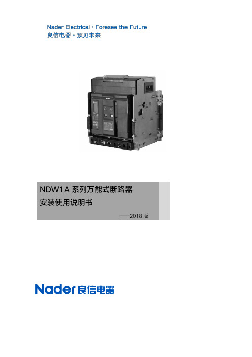
NDW1A 系列安装使用说明书
■
■
“”
“”
3
NDW1A 系列安装使用说明书
■ ■
■
4
NDW1A 系列安装使用说明书
5
NDW1A 系列安装使用说明书
6
NDW1A 系列安装使用说明书
7
NDW1A 系列安装使用说明书
8
NDW1A 系列安装使用说明书 9
NDW1A 系列安装使用说明书 39
NDW1A 系列安装使用说明书 40
NDW1A 系列安装使用说明书 41
NDW1A 系列安装使用说明书 42
NDW1A 系列安装使用说明书 43
NDW1A 系列安装使用说明书 44
NDW1A 系列安装使用说明书 45
NDW1A 系列安装使用说明书 46
下图为控制器输入输出接口
NDW1A-2000/3200/6300 辅助开关接线方式
24
NDW1A 系列安装使用说明书
25
NDW1A 系列安装使用说明书
²
²
26
NDW1A 系列安装使用说明书 27
NDW1A 系列安装使用说明书 28
NDW1A 系列安装使用说明书 29
NDW1A 系列安装使用说明书 30
注:1.断路器的当前状态为不带电,断开,连接,未贮能; 2.虚线部分由用户接; 3.电源——若 Q、F 、B、M、控制器电源不同时,分别接电源;
23
NDW1A 系列安装使用说明书 4.当主回路电流小于 0.4In 时,端子号 1、2 必须接辅助电源; 5.该原理图适用于带通讯功能的产品。 6.断路器辅助端子接线方式见附图。 7.二次端子可接导线容量,最小为 0.2mm²/24AWG,最大为 1.5mm²/16AWG。
莫萨1EDR-G902系列产品说明书

EDR-G902SeriesIndustrial secure routers with firewall/NAT/VPNFeatures and Benefits•Firewall/NAT/VPN/Router all-in-one•Secure remote access tunnel with VPN•Stateful firewall protects critical assets•Inspect industrial protocols with PacketGuard technology•Easy network setup with Network Address Translation(NAT)•Dual WAN redundant interfaces through public networks•Support for VLANs in different interfaces•-40to75°C operating temperature range(-T model)•Security features based on IEC62443/NERC CIPCertificationsIntroductionThe EDR-G902is a high-performance,industrial VPN server with a firewall/NAT all-in-one secure router.It is designed for Ethernet-based security applications on critical remote control or monitoring networks,and it provides an Electronic Security Perimeter for the protection of critical cyber assets including pumping stations,DCS,PLC systems on oil rigs,and water treatment systems.The EDR-G902Series includes the following cybersecurity features:•Virtual Private Network(VPN):VPNs are designed to provide users with secure communication links when accessing a private network from the public Internet.They use IPsec(IP Security)server or client mode for encryption and authentication of all IP packets at the network layer to ensure confidentiality and sender authentication.•Firewall:Controls network traffic between different trust work Address Translation(NAT),which shields the internal LAN from unauthorized activity from outside hosts.The EDR-G902’s Quick Automation Profile function supports most common fieldbus protocols,including EtherCAT,EtherNet/IP,FOUNDATION Fieldbus,Modbus TCP,and ers can easily create a secure Ethernet Fieldbus network from a user-friendly web UI with a single click. In addition,Moxa’s PacketGuard technology(Deep Packet Inspection)helps to filter Modbus TCP commands at OSI layer7.The wide-temperature range models that are available operate reliably in hazardous,-40to75°C environments.SpecificationsInput/Output InterfaceAlarm Contact Channels1relay output with current carrying capacity of1A@24VDCButtons Reset buttonDigital Input Channels+13to+30V for state1-30to+3V for state0Max.input current:8mAEthernet Interface10/100/1000BaseT(X)Ports(RJ45connector)11Combo Ports(10/100/1000BaseT(X)or100/1000BaseSFP+)Standards IEEE802.1Q for VLAN TaggingIEEE802.3for10BaseTIEEE802.3ab for1000BaseT(X)IEEE802.3u for100BaseT(X)and100BaseFXIEEE802.3x for flow controlIEEE802.3z for1000BaseSX/LX/LHX/ZXWAN Ports,RJ45/Fiber Combo Port1LAN Ports,RJ45port1Ethernet Software FeaturesManagement Back Pressure Flow Control,DDNS,DHCP Server/Client,HTTP,LLDP,QoS/CoS/ToS,SMTP,SNMPv1/v2c/v3,Telnet,TFTP,QoS,PPPOE,Traffic prioritizationRouting Throughput:25,000packets per second(max.300Mbps)Routing Redundancy VRRPSecurity HTTPS/SSL,SSH,IPsec,OpenVPN(client and server),UDP and TCP Tunnel mode(routing)and TAP mode(bridge),L2TP(server),RADIUSTime Management NTP Server/Client,SNTPUnicast Routing OSPF,RIPV1/V2,Static RouteSwitch PropertiesMax.No.of VLANs10DoS and DDoS ProtectionTechnology ARP-Flood,FIN Scan,ICMP-Death,NEWWithout-SYN Scan,NMAP-ID Scan,NMAP-Xmas Scan,Null Scan,SYN/FIN Scan,SYN/RST Scan,SYN-Flood,Xmas Scan FirewallDeep Packet Inspection Modbus TCPModbus UDPFilter DDoS,Ethernet protocols,ICMP,IP address,MAC address,PortsQuick Automation Profiles DNP,EtherCAT,EtherNet/IP,FOUNDATION Fieldbus,FTP,HTTP,IEC60870-104,IPsec,L2TP,LonWorks,Modbus TCP,PPTP,PROFINET,RADIUS,SSH,TelnetStateful Inspection Router firewallTransparent(bridge)firewallThroughput Max.25000packets per second(max.300Mbps)IPsec VPNAuthentication MD5and SHA(SHA-256)RSA(key size:1024-bit,2048-bit)X.509v3certificateConcurrent VPN Tunnels Max.50IPsec VPN tunnelsEncryption3DES,AES-128,AES-192,AES-256,DESProtocols IPsec,L2TP(server),PPTP(client)Throughput Max.60Mbps(Conditions:AES-256,SHA-256)NATFeatures1-to-1,bidirectional1-to-1,N-to-1,Port forwardingOpenVPNAuthentication User password by MD5and SHA1Concurrent VPN Tunnels Client Mode:max.2external serversServer Mode:max.5external clientsEncryption AES-128/192/256CBC,Blowfish CBC,DES CBC,DES-EDE3CBCProtocols OpenVPN(client and server),UDP,and TCP,Tunnel mode(routing)and TAP mode(bridge)Real-Time Firewall/VPN Event LogEvent Type Firewall event,System event,VPN eventMedia Local storage,SNMP Trap,Syslog serverSerial InterfaceConsole Port RS-232Power ParametersConnection Removable terminal blockInput Voltage12/24/48VDCInrush Current(Max.)0.45A@24VDCOverload Current Protection SupportedReverse Polarity Protection SupportedPhysical CharacteristicsHousing MetalIP Rating IP30Dimensions51x152x131.1mm(2.01x5.98x5.16in)Weight1250g(2.82lb)Installation DIN-rail mounting,Wall mounting(with optional kit)Environmental LimitsOperating Temperature EDR-G902:0to60°C(32to140°F)EDR-G902-T:-40to75°C(-40to167°F)Storage Temperature(package included)-40to85°C(-40to185°F)Ambient Relative Humidity5to95%(non-condensing)Standards and CertificationsFreefall IEC60068-2-32EMC EN55032/24EMI CISPR32,FCC Part15B Class AEMS IEC61000-4-2ESD:Contact:6kV;Air:8kVIEC61000-4-3RS:80MHz to1GHz:10V/mIEC61000-4-4EFT:Power:4kV;Signal:4kVIEC61000-4-5Surge:Power:2kV;Signal:1kVIEC61000-4-6CS:10VIEC61000-4-8PFMFMaritime DNV-GLSafety UL508Shock IEC60068-2-27Vibration IEC60068-2-6MTBFTime981,233hrsStandards Telcordia(Bellcore),GBWarrantyWarranty Period5yearsDetails See /warrantyPackage ContentsDevice1x EDR-G902Series secure routerCable1x RJ45-to-DB9console cableDocumentation1x document and software CD1x quick installation guide1x warranty cardNote SFP modules need to be purchased separately for use with this product. DimensionsOrdering InformationEDR-G9021✓0to60°CEDR-G902-T1✓-40to75°C Accessories(sold separately)SoftwareMXview Industrial network management software designed for converged automation networksStorage KitsABC-01Configuration backup and restoration tool for managed Ethernet switches and AWK Series wirelessAPs/bridges/clients,0to60°C operating temperatureSFP ModulesSFP-1FELLC-T SFP module with1100Base single-mode with LC connector for80km transmission,-40to85°Coperating temperatureSFP-1FEMLC-T SFP module with1100Base multi-mode with LC connector for4km transmission,-40to85°Coperating temperatureSFP-1FESLC-T SFP module with1100Base single-mode with LC connector for40km transmission,-40to85°Coperating temperatureSFP-1G10ALC WDM-type(BiDi)SFP module with11000BaseSFP port with LC connector for10km transmission;TX1310nm,RX1550nm,0to60°C operating temperatureSFP-1G10ALC-T WDM-type(BiDi)SFP module with11000BaseSFP port with LC connector for10km transmission;TX1310nm,RX1550nm,-40to85°C operating temperatureSFP-1G10BLC WDM-type(BiDi)SFP module with11000BaseSFP port with LC connector for10km transmission;TX1550nm,RX1310nm,0to60°C operating temperatureSFP-1G10BLC-T WDM-type(BiDi)SFP module with11000BaseSFP port with LC connector for10km transmission;TX1550nm,RX1310nm,-40to85°C operating temperatureSFP-1G20ALC WDM-type(BiDi)SFP module with11000BaseSFP port with LC connector for20km transmission;TX1310nm,RX1550nm,0to60°C operating temperatureSFP-1G20ALC-T WDM-type(BiDi)SFP module with11000BaseSFP port with LC connector for20km transmission;TX1310nm,RX1550nm,-40to85°C operating temperatureSFP-1G20BLC WDM-type(BiDi)SFP module with11000BaseSFP port with LC connector for20km transmission;TX1550nm,RX1310nm,0to60°C operating temperatureSFP-1G20BLC-T WDM-type(BiDi)SFP module with11000BaseSFP port with LC connector for20km transmission;TX1550nm,RX1310nm,-40to85°C operating temperatureSFP-1G40ALC WDM-type(BiDi)SFP module with11000BaseSFP port with LC connector for40km transmission;TX1310nm,RX1550nm,0to60°C operating temperatureSFP-1G40ALC-T WDM-type(BiDi)SFP module with11000BaseSFP port with LC connector for40km transmission;TX1310nm,RX1550nm,-40to85°C operating temperatureSFP-1G40BLC WDM-type(BiDi)SFP module with11000BaseSFP port with LC connector for40km transmission;TX1550nm,RX1310nm,0to60°C operating temperatureSFP-1G40BLC-T WDM-type(BiDi)SFP module with11000BaseSFP port with LC connector for40km transmission;TX1550nm,RX1310nm,-40to85°C operating temperatureSFP-1GEZXLC SFP module with11000BaseEZX port with LC connector for110km transmission,0to60°C operatingtemperatureSFP-1GEZXLC-120SFP module with11000BaseEZX port with LC connector for120km transmission,0to60°C operatingtemperatureSFP-1GLHLC SFP module with11000BaseLH port with LC connector for30km transmission,0to60°C operatingtemperatureSFP-1GLHLC-T SFP module with11000BaseLH port with LC connector for30km transmission,-40to85°C operatingtemperatureSFP-1GLHXLC SFP module with11000BaseLHX port with LC connector for40km transmission,0to60°C operatingtemperatureSFP-1GLHXLC-T SFP module with11000BaseLHX port with LC connector for40km transmission,-40to85°Coperating temperatureSFP-1GLSXLC SFP module with11000BaseLSX port with LC connector for500m transmission,0to60°C operatingtemperatureSFP-1GLSXLC-T SFP module with11000BaseLSX port with LC connector for500m transmission,-40to85°Coperating temperatureSFP-1GLXLC SFP module with11000BaseLX port with LC connector for10km transmission,0to60°C operatingtemperatureSFP-1GLXLC-T SFP module with11000BaseLX port with LC connector for10km transmission,-40to85°C operatingtemperatureSFP-1GSXLC SFP module with11000BaseSX port with LC connector for300/550m transmission,0to60°Coperating temperatureSFP-1GSXLC-T SFP module with11000BaseSX port with LC connector for300/550m transmission,-40to85°Coperating temperatureSFP-1GZXLC SFP module with11000BaseZX port with LC connector for80km transmission,0to60°C operatingtemperatureSFP-1GZXLC-T SFP module with11000BaseZX port with LC connector for80km transmission,-40to85°C operatingtemperaturePower SuppliesDR-120-24120W/2.5A DIN-rail24VDC power supply with universal88to132VAC or176to264VAC input byswitch,or248to370VDC input,-10to60°C operating temperatureDR-452445W/2A DIN-rail24VDC power supply with universal85to264VAC or120to370VDC input,-10to50°C operating temperatureDR-75-2475W/3.2A DIN-rail24VDC power supply with universal85to264VAC or120to370VDC input,-10to60°C operating temperatureMDR-40-24DIN-rail24VDC power supply with40W/1.7A,85to264VAC,or120to370VDC input,-20to70°Coperating temperatureMDR-60-24DIN-rail24VDC power supply with60W/2.5A,85to264VAC,or120to370VDC input,-20to70°Coperating temperatureWall-Mounting KitsWK-51-01Wall-mounting kit,2plates,6screws,51.6x67x2mmRack-Mounting KitsRK-4U19-inch rack-mounting kit©Moxa Inc.All rights reserved.Updated Nov12,2018.This document and any portion thereof may not be reproduced or used in any manner whatsoever without the express written permission of Moxa Inc.Product specifications subject to change without notice.Visit our website for the most up-to-date product information.。
ATW-A01连接套件操作和安装手册说明书

ATW Connection Kit Operation & Installation ManualATW-A01No. 0150535502• Please read this manual carefully before installation.• Keep this operation manual for future reference.Original instructionsUser ManualContentsIllustration of model (1)Safety (2)Installation procedure (5)Electrical wiring (7)Move and scrap the air conditioning (13)Illustration of model• I f the connection kit is transferred to a new user, this manual shall be transferred to the user, together with the conditioner.• B efore installation, be sure to read Safety Considerations in this manual for proper installation.• Tlikely causing the severe accidents. In general, both of them are the important items related to the security, which should be strictly abided by.• A fter the installation, perform test run to make sure everything is in normal conditions, and then operate and maintain the connection kit in accordance with the user manual. The user manual should be delivered to the user for proper keeping.• P lease ask the special maintenance station for installation and repair. Water leakage,electric shocks or fire accidents might be caused from improper installation if you conduct the installation by your own.• T he installation should be conducted properly according to this manual. Water leakage, electric shocks or fire accidents might be caused from improper installation.• P lease make sure to install the connection kit on the place where can bear the weight of the connection kit. The connection kit can’t be installed on the grids such as the non-special metal burglar-proof net. The place with insufficient support strength might cause the dropdown of the machine, which may lead to personal injuries.• T he installation should be ensured against typhoons and earthquakes, etc. The installation unconformable to the requirements will lead to accidents due to the turnover of the machine.• S pecific cables should be used for reliable connections of the wirings. Please fix the terminal connections reliably to avoid the outside force applied on the cables from being impressed on the cables. Improper connections and fixings might lead to such accidents as heating or fire accidents.• C orrect shapes of wirings should be kept while the embossed shape is not allowed. The wirings should be reliably connected to avoid the cover and the plate of the electrical cabinet clipping the wiring. Improper installation might cause such accidents as heating or fire accidents.•W hile placing or reinstalling the connection kit, except the specific refrigerant (R410A), don’t let the air go into the refrigeration cycle system. The air in the refrigeration cycle system might lead to the cracking or personal injuries due to abnormal high pressure of the refrigeration cycle system.• D uring installation, please use the accompanied spare parts or specific parts. If not, water leakage, electric shocks, fire accidents or refrigerant leakage might be caused.• D uring installation, if refrigerant leakage occurs, ventilation measures should be taken, for the refrigerant gas might generate harmful gases upon contacting the flame.• A fter installation, check if any refrigerant leakage exists. If the refrigerant gas leaks in the room, such things as air blowing heaters and stoves, etc. may generate harmful gases.• D on’t install the connection kit at the places where the flammable gases may leak. In case the gas leakage occurs around the machine, such accidents as fire disasters may be caused.• T he refrigerant gas pipe, HP gas pipe and liquid pipe should be heat insulated to preserve heat. For inappropriate heat insulation, the water caused from the condensation will drop to get the article at home wet.• T he electrical construction shall be implemented by the correspondingly qualified personnel in accordance with electrical construction standards, local electrical laws as well as specifications. Moreover, dedicated circuit must be used, rather than the wire pin. Insufficient capacity of the wire circuit and unprepared construction (if any) may cause electric shock, fires, etc.• D uring the process of grounding, the ground wire cannot be connected to the gas pipe, water pipe, lightning rod or ground wire of the telephone. Incomplete grounding may cause electric shock, fires, etc.• I nstall residual-current circuit breaker, or electric shock, fires, etc. will occur.• W hen contacting electrical components, ensure they are powered off. Contacting the live part may result in the danger of electric shock.• I f there is leakage of the refrigerant gas flow during operation, refrigerant gas is required. If the refrigerant gas contacts any fire, poisonous gases will be produced.• I f the supply cord is damaged, it must be replaced by the manufacturer, its service agent or similarly qualified persons in order to avoid a hazard.• T his appliance is not intended for use by persons (including children) with reduced physical, sensory or mental capabilities, or lack of experience and knowledge, unless they have been given supervision or instruction concerning use of the appliance by a person responsible for their safety.• C hildren should be supervised to ensure that they do not play with the appliance.• T his appliance can be used by children aged from 8 years and above and persons with reduced physical, sensory or mental capabilities or lack of experience and knowledge if they have been given supervision or instruction concerning use of the appliance in a safe way and understand the hazards involved. Children shall not play with the appliance. Cleaning and user maintenance shall not be made by children without supervision.• T he appliances are not intended to be operated by means of an external timer or separate remote-control system.• K eep the appliance and its cord out of reach of children less than 8 years.Prohibitions• T he connection kit should be effectively grounded. Electric shocks may occur if the connection kit is ungrounded or inappropriately grounded. The wire for earthing shouldn’t be connected to the connections on the gas pipe, water pipe, lightning rod or telephone.• T he breaker for electricity leakage should be mounted. If not, accidents such as electric shocks may happen.• T he installed connection kit should be checked for electricity leakage by being powered.• A fter installation, all cassette concealed connection kits should be trial-tested. After the proper operation of the machine, other fitments can be made.• W hen installing the connection kit, please fix the box and connecting pipes in an efficient way to avoid shaking when changing connection kit.• I f the ambient humidity is over 80%, when the water discharge hole is blocked or the filter becomes dirty, or airflow speed change, there may be leads to condensing water drop down, and at the same time there may be some drops of water spit out.• K eep the connection kit, power supply wiring, conductor, etc. at least 1 m away from the TV and radio to avoid image interference and noise. However, sometimes there is still noise when the distance is over 1 m due to the different states of radio waves.• T ry to install connection kit where the fluorescent lamp is far away.• W hen wireless devices are being installed, the distance that the signal from the controller will reach may be shortened in a room with a fluorescent lamp that is turned on in an electric way (frequency conversion or rapid start).• D o not use components other than the fuse of proper capacity, such as metal wire and copper wire, which will cause fires and other faults if used instead of the fuse.• W hen doing the cleaning and maintenance, make sure that the operation has been stopped and the manual power switch is in the off position.• D o not use appliances such as water heater near the connection kit. Using appliancesproducing steam near the connection kit may lead to accidents such as water leakage, electric leakage and short circuit when the cooling system is in operation.Do not install at such places1. A place that is filled with mineral oil, a kitchen which has oil and steam everywhere, etc., which may cause degradation, falling off and water leakage of the resinous components.2. A place with corrosive gases such as sulphurous acid gas, which will lead to the corrosion of the copper tube, welding joint, etc., causing refrigerant leakage.3. A place where machines give out electromagnetic waves, which will lead to abnormality and improper function of the control system.4. A place with possible leakage of combustible gases, floating of carbon fiber and combustible dust and use of volatile combustible substances such as diluents, the accumulation of which around the machine set will lead to fires.5. A place where small animals inhabit, whose contacting the inner electrical components may cause faults, smoking, outbreak of a fire, etc.6. A coastal place with high salinity and a place with great variation in voltage such as a factory, which may cause faults to vehicles and ships.Mounting dimensionMounting dimensions are shown in the Fig.1.Unit : mm ArrayFig.1 ArrayFig.2Install the lifting tools on the lifting bolts according to the instruction of the Fig.2.Be sure to follow the stipulations on products locally purchased to use nuts (M8 or M10 of 3 pieces for 4 positions) and gaskets (M8 with the outer diameter of 24~28 mm and M10 with that of 30~34 mm of 2 pieces for 4 positions) on the upper and lower sides of the lifting tools.<Note>Be sure that the product must be installed with the top surface (the oblique surface in the Fig.2) upward, or it will not work well and increase the working noise.• Electrical construction should be made with specific mains circuit by the qualified personnel according to the installation instruction. Electric shock and fire may be caused if the capacity of power supply is not sufficient.• During arranging the wiring layout, specified cables should be used as the mains line, which accords with the local regulations on wiring. Connecting and fastening should be performed reliably to avoid the external force of cables from transmitting to the terminals. Improper connection or fastness may lead to burning or fire accidents.• There must be the ground connection according to the criterion. Unreliable grounding may cause electrical shocks. Do not connect the grounding line to the gas pipe, water pipe, lightening rod and telephone line.• Only copper wire can be used. Breaker for electric leakage should be provided, or electric shock may occur.• The wiring of the mains line is of Y type. The power plug L should be connected to the live wire and plug N connected to null wire whilethe type with auxiliary electrically heating function, the live wire and the null wire should not be misconnected, or the surface of electrical heating body will be electrified. If the power line is damaged, replace it by the professional personnel of the manufacturer or service center.• The power line of connection kits should be arranged according to the installation instruction of connection kits.• The electrical wiring should be out of contact with the high-temperature sections of tubing as to avoid melting the insulating layer of cables, which may cause accidents.• After connected to the terminal tier, the tubing should be curved into be a U-type elbow and fastened with the pressing clip.• Controller wiring and refrigerant tubing can be arranged and fixed together.• The machine can't be powered on before electrical operation. Maintenance should be done while the power is shut down.• Seal the thread hole with heat insulating materials to avoid condensation.• Signal line and power line are separately independent, which can't share one line. [Note: the power line, signal line are provided by users. Parameters for power lines are shown as below: 3×(1.0-1.5) mm2; parameters for signal line: 2×(0.75-1.25)mm2( shielded line)]• Connection kits and outdoor units should be connected to the power source separately. All connection kits must share one single electrical source, but its capacity and specifications should be calculated. Indoor & outdoor units should be equipped with the power leakage breaker and the overflow breaker.• Connection kit can be installed in multiple, named as unit A, unit B…. Pay attention to the marks on the terminal block when connecting the outdoor unit with the indoor unit. Referto wiring example as described in 5-2 while ensuring correct connection. In addition, the operation will be abnormal when the wiring and the tubing between indoor and outdoor machine sets are installed in different refrigerant systems.• Energization is not to be done before it’s confirmed that the connection kit have completely installed and that the outdoor and indoor installation is completed.Before connecting the ATW-A01,please set the outdoor unit first, open the outdoor unit casing and the control box,then setting the board dial switch,make the BM1-1&1-8&2-8 as follows:1.If the outdoor unit connect with ATW-A01,make the outdoor's BM1-8 to ON.2.If DHW function is actived,Outdoor PCB set BM2-8 to on,and two options as follow:• YR-E27 together with DHW temperature sensor (Connected at CN31) which will be insented into DHW tank while Outdoor PCB BM1-1 will be set to OFF (Fig.3);•User sends on/off to CN22 while Outdoor PCB BM1-1 will be set to ON (Fig.4).Fig.3 DHW controled by YR-E27Fig.4 DHW controled by User's controllerWiring instructionsConnect the outdoor PQ to ATW-A01 PQ, extended functions are connected according to the actual situation.NO.Input Description RemarksCN31Water tank temperature sensor When use YR‐E27 to control DHW, check the temperature of water tankCN17Water replenishing switch ReserveCN20Cooling signal swatch When there is cooling demand, the dry connect is ON, otherwise is OFFCN21Heating signal swatch When there is heating demand, the dry connect is ON, otherwise is OFFCN22Hot water demand When use the user’s own, controller to control DHWCN23Frequency limiting When the dry connect is ON, the outdoor’s output will reduceCN24Out ALARM When the dry connect is ON, the outdoor will stopCN26Water temperature setting(0~+10V)ReserveCN6Connect Outdoor PQ(PQ )For communication with outdoor NO.Output Description Remarks13-Way Valve #2When the control line 1 is power on, the water to floor heating. Otherwise, the water to Fanc oi l2L(3-Way Valve)220V-L 3N(3-Way Valve)220V-N43-Way Valve #1When the control line 4 is power on, the water to DHW, otherwise ,the water to buffertank5&6Hot Water DHW Pump/7&8Reserve Reserve9&10Leakage-proof Valve Reserve11&12Auxili a ry heat source signal On/off dry connect13&14Floor Heating Valve T o cut off the water to floating15&16Air Conditioner Pump/17&18Heater(3KW Max)DHW water tank heaterCN13ALARM When the outdoor alarmed, output on dryconnect CN14MODE ON: Cooling OFF: heatingCN15ON/OFF/CN16Defrost ON: defrosting OFF: not defrostCN18OUT1ReserveThe wiring for the power line and signal line of connection kit• Power cable and communication wire must be fixed firmly.• Each connection kit must be earthed well.• When power cable exceeds the range, thicken it appropriately.• Shielded layer of communication wires must be connected together and be earthed at single point.• Communication wire total length cannot exceed 500m.The wiring for the power line of connection kit, the wiring for the signal line between connection kits and outdoor units as well as the wiring between connection kits.ItemsTotal Current of valve boxes (A)Cross Section (mm 2)Length (m )RatedCurrent ofOverflow Breaker (A)Rated Current of PowerLeakage Breaker (A)Leaking Current (mA)Operating Period (S)Cross Sectional Areaof Signal Line Outdoor -connectionkit (mm 2)Connectionkit -connectionkit (mm 2)<102202020A,30mA,0.1S or below 2cores ×0.75-2.0 mm 2 shielded line ≥10 and <15 3.5253030A,30mA, 0.1S or below ≥15 and <22 5.5304040A,30mA, 0.1S or below ≥22 and <2710405050A,30mA, 0.1S or belowNotes:(1) The above wiring example is only for reference. The number of connection kits and indoorunits shall be subject to the field installation.(2) Two-core non-polar communication line with shield shall be adopted for communication linesbetween the connection kit and the indoor/outdoor unit.(3) All connection kits within one system may share one over current breaker for power supply.But it’s necessary to compute total current capacity specification.(4) For wiring harness connected to the power terminal block, the terminal shall be pressed witha round (refer to the following figure).1)The power terminal block shall not be crimped with 2 wires of different diameters.Otherwise, poor crimp connection and looseness may lead to abnormal heating or sparking of the line.2)Refer to the following figure for crimping wires with the same diameter.Connect wires with the same diameter on both It’s forbidden to connect two wires on one sideWires with differentdiameters are not allowed1)The maximum wiring length between the outdoor machine and the valve cage, the valvecage and the indoor machine, and between valve cages is 1000 m at most. The total wiring length is 1000m at most.2)The maximum wiring length between the valve cage and the wire controller for switchingworking modes is 500 m at most.(5) Tighten terminal screws with proper screw driver. Screw driver of small dimension willdamage the screw head and fail to tighten properly.(6) If terminal screws are tightened excessively, they may be damaged. Refer to the followingtable for tightening torques of terminal screws:(7) Power line is forbidden to the communication terminal block because it will damage thecircuit control board.(8) Wiring of communication lines shall be within the following scope. Exceeding the limit willpossibly lead to abnormal communication.Dimension of terminal screw Tightening torque (N.m)M3.5 (terminal block for communication line)0.80~0.96M4 (terminal block for power line) 1.18~1.44M4 (terminal block for ground wire) 1.52~1.86Electrical wiring diagramMove and scrap the air conditioning •When moving, to disassemble and re-install the air conditioning, please contact your dealerfor technical support.•In the composition material of air conditioning, the content of lead, mercury, hexavalent chromium, polybrominated biphenyls and polybrominated diphenyl ethers are not more than 0.1% (mass fraction) and cadmium is not more than 0.01% (mass fraction).•Please recycle the refrigerant before scrapping, moving, setting and repairing the air conditioning; for the air conditioning scrapping, should be dealt with by the qualified enterprises.Qingdao Haier Air Conditioner Electric Co.,Ltd.Haier Industrial Park,Qianwangang Road,Eco-Tech Development Zone, Qingdao 266555,Shandong,P.R.C.。
vacon nxa用户手册

内容
VACON NXA用户手册
目录
1
安全
2
指令
3
收货
ቤተ መጻሕፍቲ ባይዱ
4
有源前端单元(AFE)
5
安装
6
控制面板
7
附录
Vacon China
电话:+86-10-51280006
传真: +86-10-65813733
24 小时支持热线:+86-13711105700 Emai:vacon@
2.2 EMC指令 .............................................................................................................................................. 8
2.1 CE标识.................................................................................................................................................. 8
用户手册
有源前端单元(AFE)
安装和调试时,请务必遵照以下的快速启动指南进行操作。 如有任何问题,请与当地经销商联系。
快速启动指南 1. 检查产品是否与定单相符,见第 3 章节。 2. 进行调试前,请仔细阅读第 1 章中的安全说明。 3. 进行机械安装前,检查变频器周边的最小间距和外部环境条件。 4. 检查主电源电缆/母线的尺寸、DC 输出电缆/母线及主电源熔断器、DC 熔断器的规格以及电缆的连接
- 1、下载文档前请自行甄别文档内容的完整性,平台不提供额外的编辑、内容补充、找答案等附加服务。
- 2、"仅部分预览"的文档,不可在线预览部分如存在完整性等问题,可反馈申请退款(可完整预览的文档不适用该条件!)。
- 3、如文档侵犯您的权益,请联系客服反馈,我们会尽快为您处理(人工客服工作时间:9:00-18:30)。
AWM01A控制器调试使用说明书广东申菱空调设备有限公司二零零六年六月AWM01A控制器适用于风管机/ 水冷柜机机组产品,由主板及线控器组成。
温控范围:16℃-30℃。
1.线控器面板如图所示:1、数码管;2、风机及电加热器状态指示灯;3、温度调节键;4、定时指示灯;5、定时键;6、开/关键;7、模式选择键;8、加热选择键;9、压缩机及模式指示灯;10、运行指示灯;11、加热选择指示灯2.操作说明●压缩机预加热控制器每次重新上电,将进入预热程序,此时数码管显示当前的回风温度并闪烁,在数码管闪烁期间,按下‘开/关’键,机组不能开机。
当控制器通电时间达6小时后,数码管闪烁停止,此时再按下‘开/关’键,机组进入开机状态。
2006年6月出厂的机组所用的奥微控制器都新增了这个功能。
服务员在调试的时候,如果等待不了6小时,可以长按‘开/关’键,30秒后,即可取消本次预热功能,进行正常操作。
但是,下次断电-再上电的时候,机组仍然启功功能仍然有效。
●开关机操作先选择需要的模式,然后按压‘开/关’键,即刻运行此模式;再次按压此键便关机。
在开机状态,开机指示灯长亮。
严禁频繁开/关机操作。
●模式选择模式选择包括:自动、制冷、风扇和制热,必须在关机状态设置才有效。
热泵型自动→制冷→风扇→制热 -> 自动单冷型制冷→风扇→制冷●定时设置定时设置范围:0-15小时,每按压‘定时’键一次,定时值加1小时。
●常态显示1》在正常工作状态,数码管显示当前回风温度。
2》在定时状态,定时指示灯长亮。
3》在开机状态,开机状态指示灯长亮。
二风管机功能简介●制冷模式●制热模式●风扇模式●电加热操作●定时功能●压缩机运行保护和平均能耗●故障报警●掉电记忆1 风管机用户设置●回风温度设置1.回风温度设置范围:16℃-30℃。
调节精度1℃,出厂设定24℃。
2.操作:按下温度▼或▲键,窗口显示设定温度,再通过▼、▲键直接调需要的参数。
如果5秒钟内无任何按键操作,将自动返回显示回风温度。
●除霜运行时间设置1.除霜运行时间设置范围:5min-25min。
调节精度1min,出厂设定10min。
2.操作:关机/制热模式下,按下“加热”键15秒,“加热”灯亮闪烁,再通过▼或▲键调至需要的参数,即完成此项参数的设置。
●除霜间隔时间设置1.除霜间隔时间设置范围:30min-90min。
调节精度1min,出厂设定45min。
2.操作:关机/制热模式下,按下“加热”键15秒,“加热”灯亮,再通过▼或▲键调至需要的参数,即完成此项参数的设置。
2 风管机功能描述●外设运行条件1.压缩机启动条件:制冷时,当T回风≥T设置+1℃时,启动一台压缩机;当T回风≥T设置+2℃时,激活两台压缩机;制热时,当T回风≤25℃时,允许压缩机激活。
当T回风≤T设置-1℃时,启动一台压缩机;当T回风≤T设置-2℃时,启动两台压缩机。
2.压缩机关闭条件:制冷时,当T回风≤T设置-1℃时,关闭一台压缩机;当T回风≤T设置-2℃时,关闭两台压缩机。
制热时,当T回风≥T设置+1℃时,关闭一台压缩机;当T回风≥T设置+2℃时,两台压缩机关闭。
当T回风≥27℃时,停止所有压缩机。
3.外风机运行条件(热泵时才有效,单冷/电加热无效):1》压缩机运行时对应的风机运行;.2》外风机先于压缩机开5秒,后关于压缩机5秒。
3》系统除霜时,对应外风机关闭。
4.内风机运行条件:1》系统上电后,内风机开启。
2》内风机先于压缩机/电加热开15秒。
3》系统制热时,关机时,风机延时60S关闭。
5.电加热运行条件:1.启动条件必须完全满足:1》加热选择按键使能2》室内风机开3》 T回风≤22℃时4》 T回风≤T设置-3℃时.5》当T回风≤T设置-3℃时,开第1组电加热;当T回风≤T设置-4℃时, 2组电加热全开。
2.关闭条件必须满足以下条件之一:1》加热选择按键禁止2》室内风机停;3》 T回风≥25℃时4》当T回风≥T设置-2℃时,关闭第2组电加热;当T回风≥T设置-1℃时,关闭二组电加热。
电加热运行时,指示灯亮;电加热停止,指示灯熄灭。
3.电加热有记忆功能,下次上电会记忆掉电前状态。
通过电加热选择键,可选择电加热是否需要投入运行。
●自动模式选择自动模式时:1》当T回风≥T设置+3℃时,运行制冷模式。
2》当T回风≤T设置-3℃时,运行制热模式。
●制冷模式1.制冷运行流程:选择制冷模式→开机→运行灯亮→内风机运行→外风机运行→压缩机运行2.制冷关闭流程:制冷关机→运行灯熄灭→压缩机关闭→外风机关闭●制热模式1.制热运行流程:选择制热模式→开机→运行灯亮→内风机运行→四通阀运行→外风机运行→压缩机运行/电加热启动。
2.制热关闭流程:制热关机→运行灯熄灭→电加热关闭/压缩机关闭→外风机关闭●送风模式送风运行流程:选择送风模式→开机→内风机运行。
●交替除霜功能1.除霜温度1》除霜模式下,当除霜感温器1的温度低于2℃时,开始计时;当计时大于或等于除霜间隔设置的时间且盘管温度低于-3℃,系统1开始除霜,压缩机1、内风机1开(电加热器打开),外风机1和四通阀1关闭。
2》同上,系统2满足除霜条件,系统2开始除霜。
(在计时其间盘管温度高于3℃,计时清零。
)3》系统1或系统2除霜其间,数码管显示“dF”。
2.设置为双系统除霜1》进入条件:当系统1和系统2谁先满足条件,谁先除霜;若系统1和系统2都满足除霜条件时,系统执行交替除霜,比如:系统1除霜时,系统2处于制热等待状态,系统1除霜结束后,系统2立即进入除霜。
2》除霜过程:除霜系统的压机运行,四通阀关闭,外风机关闭,内风机和电加热运行。
没有除霜的系统保持制热模式。
3》除霜结束:哪个系统满足除霜结束条件,便退回到制热模式。
3.除霜退出:当除霜感温器检测温度高于15℃,或除霜运行时间已等于除霜运行设置时间,或者高压开关跳开,便退出除霜回到制热状态。
●风管机感温器描述1.回风温度感温器(TH1):检测回风温度,用于压缩机开启或关闭的判定。
2.除霜温度感温器1(TH4):检测室外盘管1的温度,用于在制热状态时,判定系统1除霜开启和除霜的必要条件。
3.除霜温度感温器2(TH5):检测室外盘管2的温度,用于在制热状态时,判定系统2除霜开启和除霜的必要条件。
三水冷柜机功能简介●自动模式●制冷模式●风扇模式●电加热操作●定时功能●压缩机运行保护和平均能耗●故障报警●掉电记忆1 水冷柜机用户设置●回风温度设置1.回风温度设置范围:16℃-30℃。
调节精度1℃,出厂设定24℃。
2 操作:首次按下温度▼或▲键,窗口显示设定温度,再通过▼、▲键直接调需要的参数。
如果5秒钟内无任何按键操作,将自动返回显示回风温度。
2 水冷柜功能描述●外设运行条件1.压缩机启动条件:制冷时,当T回风≥T设置+1℃时,启动一台压缩机;当T回风≥T设置+2℃时,激活两台压缩机;当T回风≥T设置+3℃时,启动三台压缩机。
2.压缩机关闭条件:制冷时,当T回风≤T设置-1℃时,关闭一台压缩机;当T回风≤T设置-2℃时,关闭两台压缩机;当T回风≤T设置-3℃时,关闭三台压缩机。
3.内风机运行条件:1》系统上电后,内风机开启。
2》内风机先于压缩机/电加热开15秒。
3》系统制热时,关机风机延时60S关闭4.电加热运行条件:1.启动条件必须完全满足:1》加热选择按键使能2》室内风机开3》当T回风≤T设置-1℃时,开第1组电加热;当T回风≤T设置-2℃时,开2组电加热。
2.关闭条件必须满足以下条件之一:1》加热选择按键禁止2》室内风机停;3》 T回风≥27℃时4》当T回风≥T设置+1℃时,关闭第2组电加热;当T回风≥T设置+2℃时,关闭2组电加热。
电加热运行时,指示灯亮;电加热停止,指示灯熄灭。
3.电加热有记忆功能,下次上电会记忆掉电前状态。
通过电加热选择键,可选择电加热是否需要投入运行。
●自动模式选择自动模式时:1.当T回风≥T设置+3℃时,运行制冷模式。
2.当T回风≤T设置-3℃时,激活电加热。
●制冷模式1.制冷运行流程:选择制冷模式→开机→运行灯亮→内风机运行→压缩机运行2.制冷关闭流程:制冷关机→运行灯熄灭→压缩机关闭→内风机关闭●制热模式1.制热运行流程:选择制热模式→开机→运行灯亮→内风机运行→电加热1启动→电加热2启动。
2.制热关闭流程:制热关机→运行灯熄灭→电加热1关闭→电加热2关闭→内风机延时一分钟关闭。
●送风模式送风运行流程:选择送风模式→开机→内风机运行。
●风管机感温器描述回风温度感温器(TH1):检测回风温度,用于压缩机开启或关闭的判定。
四定时功能1定时时间范围:0~15小时2在开机状态,定时结束时执行关机;在关机状态,定时结束时执行开机。
3在定时期间开/关机,定时设置将清零。
在定时期间,定时指示灯常亮。
五压缩机运行保护和平均能耗1压缩机最小运行时间是1分钟。
如按开关键则立即关闭。
2压缩机最小停止的时间是3分钟。
3为保证三台压缩机平均磨损,系统自动为压缩机计时,先启动运行时间最短的压缩机。
六故障报警1.系统设定了11路故障输入,1路故障输出报警开关,见表1.02.一旦发生故障,数码管显示相应的故障代码,并完成故障处理,报警输出开关也随之闭合。
3.当两种或两种以上故障同时发生时,系统会对各故障分级处理。
(断开故障输入端为故障报警;接通故障输入端为正常。
)4.当故障解除后,系统仍然保持故障显示状态(为提醒用户机组需要检修),只有重新开关机才能恢复故障。
感温器故障(-40度/80度)。
控制器温度显示范围:0度~~60度。
5.低压开关检测:低压开关跳开时间满45S,关闭压缩机,低压报警。
6.风压差检测(单冷风管机或热泵机才有):上电激活风机后,延时15秒检测风压开关是否闭合,若开关未闭合,则系统停机,显示故障代码及停机。
待机状态不检测。
表1.0-系统故障代码对照表1.1-系统设置(主板跳线)表1.2-输入/输出接点一览表广东申菱空调设备有限公司AWM01A控制器调试使用说明10 附录1:水冷柜机连接图10广东申菱空调设备有限公司AWM01A控制器调试使用说明11 附录2:风管机连接图11。