3.智能压力传感器_SPS300A,B_azbil_中文
ASDX系列压力传感器说明书

ASDXRRX015PDAA 5ASDXAVX100PGAA5ASDXAVX100PGAA5ASDXAVX015PGAA5ASDXACX030PA7A5±DESCRIPTIONThe ASDX Series is a Silicon Pressure Sensor offering either an I 2C or SPI digital interface for reading pressure over the specified full scale pressure span and temperature range.The ASDX is fully calibrated and temperature compensated for sensor offset, sensitivity, temperature effects and non-linearity using an on-board Application Specific Integrated Circuit (ASIC). Calibrated output values for pressure are updated at approximately 1 kHz.The standard ASDX is calibrated over the temperature range of 0 °C to 85 °C [32 °F to 185 °F]. The sensor is characterized for operation from a single power supply of either 3.3 Vdc or 5.0 Vdc.These sensors are available to measure absolute, differential and gage pressures. The absolute versions have an internal vacuum reference and an output value proportional to absolute pressure. Differential versions allow application of pressure to either side of the sensing diaphragm. Gage versions are referenced to atmospheric pressure and provide an output proportional to pressure variations from atmosphere.The ASDX Series sensors are intended for use with non-corrosive, non-ionic working fluids such as air and dry gases. They are designed and manufactured according to standardsin ISO 9001.FEATURESOutput options: I 2C- or SPI-compatible 12-bit digitalPrecision ASIC conditioning and temperaturecompensated over 0 °C to 85 °C [32 °F to 185 °F]temperature rangeLow operating voltageAbsolute, differential and gage typesPressure ranges from 10 inches H 20 to 100 psiStandard calibrations in inches H 20, cm H 20, psi, mbar,bar, kPaTotal error band of ±2.0% of full scale span maximumRoHS compliantPOTENTIAL APPLICATIONSFlow calibratorsVentilation and air flow monitorsGas flow instrumentationSleep apnea monitoring and therapy equipmentBarometryPneumatic controls HVAC2/sensingTable 1. Absolute Maximum Ratings 1 ParameterMin Max Unit Supply voltage (V supply ) -0.3 6.0 Vdc Voltage to any pin-0.3 V supply + 0.3Vdc Digital clock frequency: I 2C SPI100 50 400 800 kHz ESD susceptibility (human body model) 3 - kV Storage temperature-50 [-58]125 [257] °C [°F] Lead temperature (2 s to 4 s)- 250 [482] °C [°F] External capacitance between V supply and ground 2 100 470nFTable 2. Operating Specifications ParameterMin. Typ. Max. Unit Supply voltage: (V supply )3 3.3 Vdc 5.0 VdcSensors are either 3.3 Vdc or 5.0 Vdc per the Order Guide (see Figure 1).3.04.75 3.345.04 3.6 5.25VdcSupply current2.03.5 5.0 mA Compensated temperature range 5 0 [32] - 85 [185] °C [°F] Operating temperature range 6 -20 [-4]- 105 [221] °C [°F]Overpressure 7 2X operating pressure range minimum Burst pressure 83X operating pressure range minimumStartup time (power up to data ready) - 2.8 7.3 ms Response time- 0.46 - ms I 2C or SPI voltage level low - - 0.2 V supply I 2C or SPI voltage level high0.8 - - V supply Pull-up on SDA and SCL (I 2C output only) 1 - - kOhm Total error band 9 - - 2.0 %FSS 10 Output resolution12- - bitsTable 3. Environmental Specifications Parameter Characteristic Humidity 0% to 95% RH non-condensing Vibration 10 G at 20 Hz to 2000 Hz Shock 100 G for 11 ms Life 1 million cycles minimum Table 4. Wetted Materials 11 Parameter Port 1 (Pressure Port)12 Port 2 (Reference Port)12 Covers glass-filled PBT glass-filled PBT Adhesives silicone silicone and epoxy Electronic components silicon and glass silicon, glass, and goldNotes:1. Absolute maximum ratings are the extreme limits that the device will withstand without damage to the device.2. An external bypass capacitor is required across the supply voltage (Pins 6 and 3 – see Figure 4) as close to the sensor supply pin as possiblefor correct sensor operation.3. Ratiometricity of the sensor (the ability of the output to scale to the input voltage) is achieved within the specified operating voltage for eachoption. Other custom supply voltages are available, please contact Honeywell Customer Service.4. The sensor is not reverse polarity protected. Incorrect application of excitation voltage or ground to the wrong pin may cause electrical failure.5. The compensated temperature range is the temperature range (or ranges) over which the sensor will produce an output proportional topressure within the specified performance limits.6. The operating temperature range is the temperature range over which the sensor will produce an output proportional to pressure but may notremain within the specified performance limits.7. Overpressure is the maximum pressure which may safely be applied to the product for it to remain in specification once pressure is returned tothe operating pressure range. Exposure to higher pressures may cause permanent damage to the product.8. Burst pressure is the maximum pressure that may be applied to any port of the product without causing escape of pressure media. Productshould not be expected to function after exposure to any pressure beyond the burst pressure.9. Total error band is the maximum deviation in output from ideal transfer function over the entire compensated temperature and pressure range.Includes all errors due to offset, full scale span, pressure non-linearity, pressure hysteresis, repeatability, thermal effect on offset, thermal effect on span and thermal hysteresis. Specification units are in percent of full scale span (%FSS).10. Full scale span (FSS) is the algebraic difference between the output signal measured at the maximum (Pmax.) and minimum (Pmin.) limits ofthe pressure range.11. Consult Honeywell Customer Service for detailed material information.12. For AC pressure p ort configuration, the “pressure” and “reference” ports are reversed.Honeywell Sensing and Control3Figure 1. Nomenclature and Order GuideASDX_ __ _ _ _ _ __Power Supply Voltage3 = 3.3 Vdc 5 = 5.0 VdcPackage Selection13Calibration SelectionSeriesGage -010NG = 10 in H 2O-025CG = 25 cm H 2O 001PG = 1 psi 005PG = 5 psi 015PG = 15 psi 030PG = 30 psi 100PG = 100 psi -025MG = 25 mbar 050MG = 50 mbar 100MG = 100 mbar 200MG = 200 mbar 500MG = 500 mbar 001BG = 1 bar 002BG = 2 bar 007BG = 7 bar 003KG = 3 kPa 004KG = 4 kPa 005KG = 5 kPa 010KG = 10 kPa 020KG = 20 kPa 050KG = 50 kPa 100KG = 100 kPa 200KG = 200 kPa 700KG = 700 kPaDifferential 005ND = ±5 in H 2O 010ND = ±10 in H 2O 015CD = ±15 cm H 2O 025CD = ±25 cm H 2O 001PD = ±1 psi 005PD = ±5 psi 015PD = ±15 psi 030PD = ±30 psi -015MD = ±15 mbar 025MD = ±25 mbar 050MD = ±50 mbar 100MD = ±100 mbar 200MD = ±200 mbar 500MD = ±500 mbar 001BD = ±1 bar 002BD = ±2 bar -003KD = ±3 kPa 004KD = ±4 kPa 005KD = ±5 kPa 010KD = ±10 kPa 020KD = ±20 kPa 050KD = ±50 kPa 100KD = ±100 kPa 200KD = ±200 kPa - Absolute - -- - --015PA = 15 psi 030PA = 30 psi 100PA = 100 psi ------001BA = 1 bar 002BA = 2 bar 007BA = 7 bar ------100KA = 100 kPa 200KA = 200 kPa 700KA = 700 kPaPressure Range 16, 17, 18Transfer Function Limits 14A = 10% to 90% calibrationB = 5% to 95% calibrationOutput Type 15S = SPI2 = I 2C, Address 0x283 = I 2C, Address 0x384 = I 2C, Address 0x485 = I 2C, Address 0x586 = I 2C, Address 0x687 = I 2C, Address 0x78_Pressure PortAV = Axial port on top, vented cover on bottomRR = Radial port on top, radial port on bottomAC = Axial port, sealed cover (commonly used for absolute)RV = Radial port, singleFuture OptionX13. Other package combinations are possible, please contact Honeywell Customer Service.14. The transfer function limits define the output of the sensor at a given pressure input. By specifying the output signal at the maximum (Pmax.)and minimum (Pmin.) limits of the pressure range, the complete transfer curve for the sensor is defined. See Figure 2 for a graphicalrepresentation of each calibration. For the 12-bit digital output, Table 6 provides the output of the sensor at significant percentages. These outputs are valid at the rated input voltage of the sensor.15. The output type defines which communication protocol the sensor uses to communicate. Available protocols are I 2C or half duplex SPI (sensoracts only as a slave). This communication protocol is not field selectable, and must be defined when ordering the sensor. 16. Custom pressure ranges are available, please contact Honeywell Customer Service.17. The pressure units (inches H 20, cm H 20, psi, mbar, bar, kPa) define the units used during calibration and in the application. 18. See Table 5 for an explanation of sensor types.4 /sensingTable 5. Sensor Types Type DescriptionAbsoluteOutput is proportional to difference between applied pressure and built-in reference to vacuum (zero pressure). GageOutput is proportional to difference between applied pressure and atmospheric (ambient) pressure.DifferentialOutput is proportional to difference between pressure applied to each of the pressure ports (Port 1 – Port 2).Figure 2. Transfer Functions and Limits A Calibration, 10% to 90%B Calibration, 5% to 95%Table 6. Sensor Output at Significant Percentages% Output Digital Counts (dec)Digital Counts (hex)0% 0 0x0000 5% 819 0x0333 10% 1638 0x0666 50% 8192 0x2000 90% 14746 0x399A 95% 15565 0x3CCD 100% 16383 0x3FFFFigure 3. Completed Catalog Listing Example ASDXAVX001PG2A3: AV pressure port, 1 psi gage, I 2C output (Address 0x28), 10% to 90% calibration at 3.3 Vdc operation.ASDXAVX001PG2A3 Output vs PressureHoneywell Sensing and Control5Figure 4. Dimensional Drawings (For reference only: mm [in].)AV Package (Legacy G2)RR Package (Legacy D4) AC Package (Legacy A2)RV PackageTable 7. PinoutI 2C SPI Pin Definition Type DescriptionPin Definition Type Description1 SDA digital I/O serial bidirectional data; data is clocked in or out on clock edge of SCL1 MISO digital output “Master In Slave Out” - serial output data; data is clocked out on clock edge of SCK2 SCL digital input serial clock input; used to clock data on SDA 2 SCK digital input serial clock input; used to clock data on MISO3 GND supply power supply ground 3 GND supply power supply ground4 N/C not used do not connect in the application4 N/C not used do not connect in the application5 SS digital output interrupt signal (conversion complete output) 5 SS digital input slave select6 Vsupply supply power supply source 6 Vsupply supply power supply source7 N/C not used do not connect in the application7 N/C not used do not connect in the application8N/Cnot useddo not connect in the application8N/Cnot useddo not connect in the applicationSensing and Control Honeywell1985 Douglas Drive NorthGolden Valley, MN 55422 /sensing 008095-11-EN IL50 GLO Printed in USAJuly 2010Copyright © 2010 Honeywell International Inc. All rights reserved.WARNINGWARRANTY/REMEDYHoneywell warrants goods of its manufacture as being free of defective materials and faulty workmanship. Honeywell’s standard product warranty applies unless agreed to otherwise by Honeywell in writing; please refer to your order acknowledgement or consult your local sales office for specific warranty details. If warranted goods are returned to Honeywell during the period of coverage, Honeywell will repair or replace, at its option, without charge those items it finds defective. The foregoing is buyer’s sole r emedy and is in lieu of all other warranties, expressed or implied, including those of merchantability and fitness for a particular purpose. In no event shall Honeywell be liable for consequential, special, or indirect damages.While we provide application assistance personally, through our literature and the Honeywell web site, it is up to the customer to determine the suitability of the product in the application.Specifications may change without notice. The information we supply is believed to be accurate and reliable as of this printing. However, we assume no responsibility for its use.WARNINGMISUSE OF DOCUMENTATIONThe information presented in this product sheet is forreference only. Do not use this document as a productinstallation guide.Complete installation, operation, and maintenanceinformation is provided in the instructions supplied witheach product.Failure to comply with these instructions could result in death or serious injury.SALES AND SERVICEHoneywell serves its customers through a worldwide network of sales offices, representatives and distributors. For application assistance, current specifications, pricing or name of the nearest Authorized Distributor, contact your local sales office or:E-mail:*********************Internet: /sensingPhone and Fax:Asia Pacific +65 6355-2828; +65 6445-3033 FaxEurope +44 (0) 1698 481481; +44 (0) 1698 481676 Fax Latin America +1-305-805-8188; +1-305-883-8257 FaxUSA/Canada +1-800-537-6945; +1-815-235-6847+1-815-235-6545 FaxASDXACX100PAAA 5ASDXAVX015PG7A5ASDXAVX030PGAA5ASDXRRX005NDAA5ASDXRRX015PDAA5ASDXRRX015PGAA 5ASDXRRX030PDAA5ASDXRRX030PGAA5ASDXRRX100PD2A5ASDXRRX100PGAA5ASDXRRX015PDAA 5ASDXAVX100PGAA5ASDXAVX100PGAA5ASDXAVX015PGAA5ASDXACX030PA7A5。
智能压力传感器_开关SPS300A_B使用说明书
电源频率 消耗功率
● 环境条件 请勿在有可燃性液体或者蒸气的环境下使用,否则会损坏本机的安全性。 使用温度范围 - 20 ~+ 60℃ 使用湿度范围 0 ~ 90%RH/40℃ 容许振動 4.9m/s2 以下 (10 ~ 60Hz) 过电压类型 Category Ⅱ (IEC60364-4-443, IEC60664-1) 汚染度 Pollution degree 2 ● 机器的设置 为避免仪表操作者触摸仪表背面端子,请务必将本机安装到盘上。 4 ~ 20mA 输出的共模电压 : 对大地间的电压小于等于 33V r.m.s.、峰值小于等 于 46.7V、小于等于 DC70V。 ● 适合规格 ※ EN61010-1 、EN61326 ※ 附热带处理(型号的最后是 B,T)的产品不对应 EN61010-1。
品 名 本体 使用说明书
C -1245 CP-UM
型 号 SPS300A/B CP-UM-1425
数量 1 1
备 注 型号构成 4 页
使用说明
书
阿自倍尔
株式会社
壁挂安装套件 盘装套件
- -
1 1
仅用于壁挂安装型 的构成
本使用说明书构成如下。 第 1 章 概 要 对 SPS300A/B 的概要进行说明。 第 2 章 各部份的名称 对 SPS300A/B 的各部份的名称进行说明。 第 3 章 设置 • 安装 对 SPS300A/B 的设置 • 安装方法进行说明。 第 4 章 接 线 对 SPS300A/B 的配线进行说明。 第 5 章 操作方法 使 SPS300A/B 动作的必要的设定方法的说明。 第 6 章 故障处理 SPS300A/B 的报警代码显示及使用过程中发生故障时的故障处 理方法的说明。 第 7 章 维 护 SPS300A/B 的维护及部品更换方法的说明。 第 8 章 废 弃 废弃 SPS300A/B 的方法的说明。 第 9 章 规 格 SPS300A/B 的规格、外形尺寸及附属品 • 可选部品等的说明。
图尔克PS300系列智能压力传感器
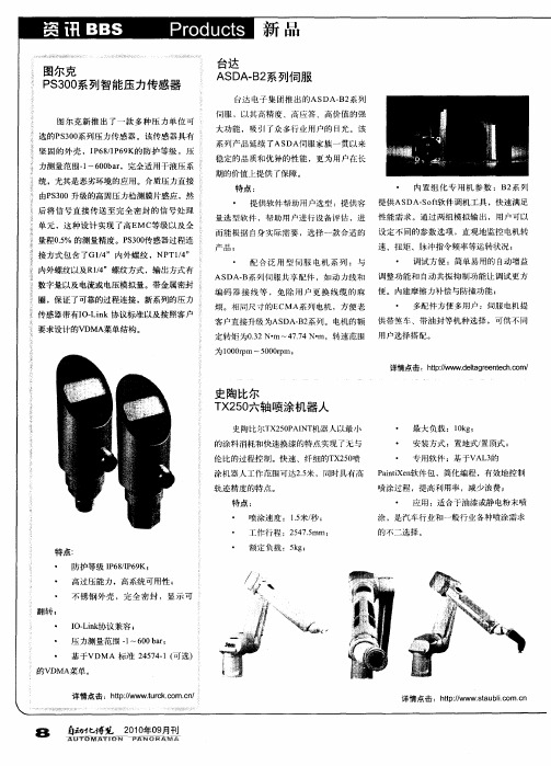
而能 根 据 自身 实际 需要 ,选 择 一款 合适 的 设 定 不同 的参 数 选项 ,直 观地 监 控 电机转
产品;
・
速 、扭矩 、脉 冲指 令频率 等运 转状 况 ;
配 合 泛 用 型 伺 服 电机 系列 :与
・
调试 方便 :简单 易用的 自动 增益
内外 螺纹 以及R1 ”螺 纹 方式 ,输 出方式 有 / 4 数 字量以及 电流 或 电压 模拟 量 。带金 属密封 圈,保证 了可靠 的过程 连接 ,新 系歹 压 力 怕
为1 0 rm~5 0 rm; 0 0p 0 0p
详情点击 :h p /w . l g e t h o / t : wd t r n c . m t/ w ea e e c
史陶比尔 T 20 X 5 六轴 喷涂机器人
史陶 比尔T 2 0A N 机 器人以最 小 X 5P I T 的涂 料 消耗和 快速 换漆 的特点 实现 了无 与 伦 比的过 程控制 。快 速 、纤 细 的T 20 X 5 喷 涂机 器人 工作 范 围可达25 ,同时具 有高 . 米 轨迹 精度 的特点 。 特点:
・
・ ・
最大 负载 : 1k ; 0g 安装 方式 :置地 式/ 置顶式 ;
・ 专 用软 件 :基于V L 的 A 3 Pi i n 件包 ,简化编程 ,有 效地控 制 at 软 n Xe 喷涂过 程 ,提高 利用 率 ,减 少 浪费 ; ・ 应 用 :适合 干油漆 或静 电粉末 喷
AS A— 系 列伺 服共 享 配件 ,如 动 力线和 调 整功 能和 自动共振 抑 制功 能让 调 试更 方 D B 编 码 器 接 线 等 , 免 除 用 户 更 换 线 缆 的麻 便 。内建 摩擦 力补 偿与防撞 功 能 ; 烦 。相 同尺 寸的E MA系列 电机 ,方便 老 C
德国制造的4位数字数字显示压力传感器说明书

1:4-digit alphanumeric display 2:LEDs3:Programming buttonMade inGermanyProduct characteristics Combined pressure sensor ConnectorProcess connection:G 1A /Aseptoflex Vario Display units:bar,psi,MPa,%of the span Function programmable2-wire connection technology:analogue output3-wire connection technology:2outputsOUT1=switching outputOUT2=switching output or analogue output 4-digit alphanumeric displayMeasuring range:-1.00...10.00bar /-14.5...145.0psi /-0.100...1.000MPa Application Type of pressure:relative pressureHygienic systems,viscous media and liquids with suspended particlesLiquids and gasesApplication5MPa 725psi 50bar Pressure rating 15MPa 2175psi 150bar Bursting pressure min.5MPa725psi50barMAWP (for applications according to CRN)-25...125(145max.1h)Medium temperature [°C]Electrical data 2wires DC /3wires DC PNP/NPNElectrical design 20...32DC (2L)/18...32DC (3L)Operating voltage [V] 3.6...21(2L)/<45(3L)Current consumption [mA]>100(500V DC)Insulation resistance[MΩ]III Protection classyesReverse polarity protection Outputs 2-wire connection technology:analogue output3-wire connection technology:2outputsOUT1=switching outputOUT2=switching output or analogue outputOutput1x normally open /normally closed programmable +1x normally open /normallyclosed programmable or 1x analogue (4...20/20...4mA,scalable)Output function ---(2L)/250(3L)Current rating [mA]---(2L)/<2(3L)Voltage drop[V]pulsed Short-circuit protection yesOverload protection ---(2L)/125(3L)Switching frequency [Hz]I:4...20mA (Ineg:20...4mA)Analogue output 300(2L)/max.(Ub -10V)x 50(3L)Max.load[Ω]Measuring /setting range -0.100...1.000MPa -14.5...145.0psi -1.00...10.00bar Measuring range Setting range -0.098...1.000MPa -14.2...145.0psi -0.98...10.00bar Set point,SP -0.100...0.998MPa -14.5...144.7psi -1.00...9.98bar Reset point,rP-0.100...0.750MPa -14.5...108.7psi -1.00...7.50bar Analogue start point,ASP 0.150...1.000MPa21.8...145.0psi1.50...10.00barAnalogue end point,AEP 0.001MPa0.1psi0.01barin steps of SP1=2.50bar;rP1=2.30bar SP2=7.50bar;rP2=7.30bar ASP =0.00bar;AEP =10.00barFactory settingAccuracy /deviations Accuracy /deviations(in %of the span)Turn down 1:1<±0.2Switch point accuracy <±0.2Characteristics deviation *)<±0.15Linearity <±0.15Hysteresis <±0.1Repeatability **)<±0.1Long-term stability ***)Temperature coefficients (TEMPCO)in the temperature range 0...70°C (in %of the span per 10K)<±0.05Greatest TEMPCO of the zero point <±0.15Greatest TEMPCO of the span Reaction times 1(2L)/0.5(3L)Power-on delay time [s]---(2L)/3(3L)Min.response time switching output[ms]0.00...30.00Damping for the switching output (dAP)[s]0.01...99.99Damping for the analogue output (dAA)[s]45(2L)/7(3L)Step response time analogue output[ms]yesIntegrated watchdog Interfaces IO-Link Device COM2(38.4kBaud)Transfer type 1.0IO-Link revision 157d /00009D hIO-Link Device ID no profile Profiles yes SIO modeA Required master port type 1Process data analogue 2Process data binary 2.3Min.process cycle time [ms]Environment -25...80Ambient temperature [°C]-40...100Storage temperature [°C]IP 67/IP 68/IP 69KProtection Tests /approvals EMCDIN EN 61000-6-2DIN EN 61000-6-3Shock resistance 50g (11ms)DIN EN 60068-2-27:Vibration resistance 20g (10...2000Hz)DIN EN 60068-2-6:160MTTF[Years]Mechanical data G 1A /Aseptoflex VarioProcess connection ceramics (99.9%Al2O3);PTFE;stainless steel 316L /1.4435;surfacecharacteristics:Ra <0.4/Rz 4Materials (wetted parts)stainless steel 316L /1.4404;FPM;PTFE;PBT;PEI;PFAHousing materials 100million Switching cycles min.0.313Weight[kg]Displays /operating elements DisplayLED green Display unit LED yellowSwitching status 4-digit alphanumeric display Function display 4-digit alphanumeric displayMeasured values Electrical connection M12connector;Gold-plated contactsConnection Wiring1connection for2-wire operation2connection for3-wire operation3connection for IO-Link parameter setting(P=communication via IO-Link)RemarksRemarks(2L)=value for2-wire operation(3L)=value for3-wire operation*)linearity,incl.hysteresis and repeatability;(limit value setting to DIN16086)**)with temperature fluctuations<10K***)in%of the span per year1Pack quantity[piece]ifm electronic gmbh•Friedrichstraße1•45128Essen—We reserve the right to make technical alterations without prior notice.—GB—PI2794—16.04.2013。
智能阀门定位器(远程型)-azbilcorporationazbil
产品技术规格若有变更,恕不另行通知。
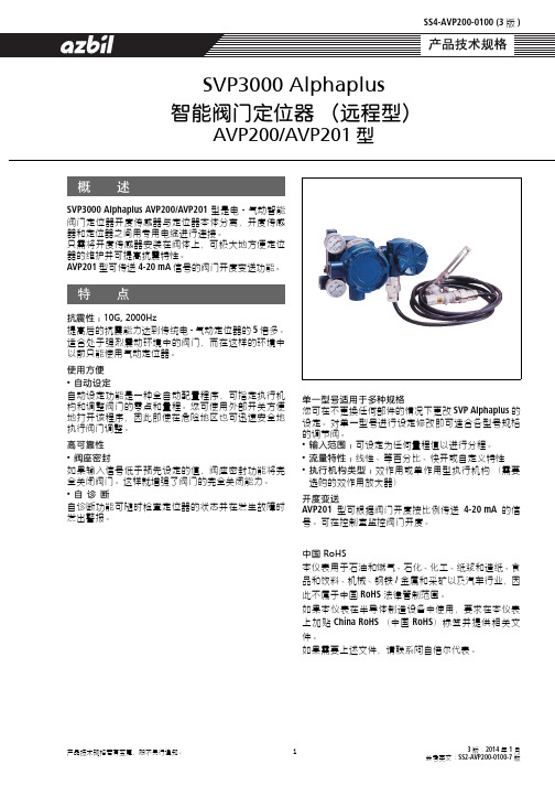
1SVP3000 Alphaplus AVP200/AVP201型是电-气动智能阀门定位器开度传感器与定位器本体分离,开度传感器和定位器之间用专用电缆进行连接。
只需将开度传感器安装在阀体上,可极大地方便定位器的维护并可提高抗震特性。
AVP201型可传送4-20 mA 信号的阀门开度变送功能。
抗震性:NMdI=OMMMeò提高后的抗震能力达到传统电-气动定位器的5倍多。
适合处于强烈震动环境中的阀门,而在这样的环境中以前只能使用气动定位器。
使用方便•自动设定自动设定功能是一种全自动配置程序,可指定执行机构和调整阀门的零点和量程。
您可使用外部开关方便地打开该程序,因此即使在危险地区也可迅速安全地执行阀门调整。
高可靠性•阀座密封如果输入信号低于预先设定的值,阀座密封功能将完全关闭阀门。
这样就增强了阀门的完全关闭能力。
•自诊断自诊断功能可随时检查定位器的状态并在发生故障时发出警报。
概 述特 点单一型号适用于多种规格您可在不更换任何部件的情况下更改SVP Alphaplus 的设定。
对单一型号进行设定修改即可适合各型号规格的调节阀。
•输入范围:可设定为任何量程值以进行分程。
•流量特性:线性、等百分比、快开或自定义特性•执行机构类型:双作用或单作用型执行机构(需要选购的双作用放大器)开度变送AVP201型可根据阀门开度按比例传送4-20 mA 的信号。
可在控制室监控阀门开度。
中国=oçep本仪表用于石油和燃气、石化、化工、纸浆和造纸、食品和饮料、机械、钢铁/金属和采矿以及汽车行业,因此不属于中国 RoHS 法律管制范围。
如果本仪表在半导体制造设备中使用,要求在本仪表上加贴 China RoHS (中国 RoHS )标签并提供相关文件。
如果需要上述文件,请联系阿自倍尔代表。
psmPMMM=^äéÜ~éäìë智能阀门定位器(远程型)^smOMML^smOMN型3版:2014年1月参考英文:SS2-AVP200-0100-7版SS4-AVP200-0100 (3版)阿自倍尔公司2适用的执行机构单作用和双作用型执行机构直行程和角型行程执行机构认 证qffp 隔爆认证本体:Ex d IIC T6认证No. TC17094开度传感器:Ex d IIC T6认证No.C18270控制信号输入4-20 mA DC (可设定为任何需要的量程,分程最小范围4 mA DC ),最小工作电流:3.85 mA对于AVP201型,当信号输入小于3.85 mA ,将无输出电流。
智能电子式压力传感器说明书

36智能电子式压力传感器说明书IP68模拟量输出RM-PA1140/50-PA41-CN-V1.147面板控制与显示功能特征Output 1滞后功能/N.O.(Hno)滞后功能/N.C.(Hnc)视窗功能/N.O.(Fno)视窗功能/N.C.(Fnc)Output 2模拟输出4~20 mA(I)模拟输出0~10 V(U)从压力传感器 探测到系统当前的压力,显示系统当前压力(bar ;Psi;kgf;MPa),同时根据设置输出状态,产生两个输出信号。
滞后作用如果系统压力与预设的差不多,那么滞后现象保持在输出平稳的状态。
当系统压力增大的时候,输出端能够达到打开开关的点(SP1);当系统压力再一次减小时,输出端能够达到关闭开关的点(rP1)。
滞后调整的方法:首先打开开关的点确定好,然后根据不同的要求再重新确定。
压力 通过视窗的作用能监测到明确的可以被接受的值。
当系统在开(SP1) 和关 (rP1) 之间变化时,输出接通 (视窗作用/常开) 或不接通 (视窗作用/常闭)。
通过 SP1 和 rP1的不同可以设定视窗的宽度。
SP1为上限值,rP1为下限值。
Psp rPt滞后Hno Hnc视窗功能101049运行模式(正常工作模式)·当外部提供电压时,装置为工作模式,根据它所设置的参数来监控和开关输出。
·模拟信号的输出值与系统压力有关。
·数码管显示表明当前系统的压力,红色二极管发光表示晶体管输出时开关的状态。
()·MODE/ENTER MODE/E 键键显示模式显示参数和设置参数值当很快按下“”键时,装置为参数值可读的显示模式,装置内部的进程和输出仍然为工作模式。
·每按一下“NTER”,就会出现一个参数名称。
·当快速按“LEARN/SET”时,对应的参数值显示5秒,5秒以后装置回到工作模式。
设置模式(参数值的设定)选择确定一个参数值后(显示模式),装置就会经过一个设置模式,一直按着“LEARN/SET”键直到显示的参数值改变, 装置的内部仍为工作模式。
FESTO SPAE 电子压力传感器说明书
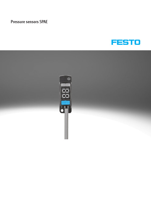
Pressure sensors SPAE2d Internet: /catalogue/...Subject to change – 2023/08Pressure sensors SPAEKey featuresAt a glance• Single-button operation • 7-segment display• Switching status indication• Various pneumatic connection options• Choice of pressure rangesFunctionThe SPAE is an electronic pressure sensor with piezoresistive pressure measuring cell, integrated signal processing, pressure indicator with percentage, control button and a switching output, PNP/NPN switchable. Two switching signals and the measured value can be transmitted via IO-Link.• The sensor can be set using the key and display oralternatively using IO-Link or teach-in• Switching functions: threshold value or window comparator• Switching logic: normally open (NO) or normally closed (NC)• Threshold values and hysteresis are adjustable• Display of minimum and maximum measured values• Display can be rotated and switched off• Protection against tampering using security code• All parameters that have been input can be transferred to other SPAE(replicator function)H- -NoteThe version with 10 mm cartridge is designed for the vacuum generator OVEL.Pressure sensors SPAE Peripherals overview3 2023/08 – Subject to change d Internet: /catalogue/...4d Internet: /catalogue/...Subject to change – 2023/08Pressure sensors SPAEType codesH- -NotePressure measuring range: Additional pressureranges on request (batch size 40)52023/08 – Subject to changed Internet: /catalogue/...Pressure sensors SPAEData sheetFunction-P- Voltage 18 ... 30 V DC-L- Pressure measuring range –1 ... +10 bar -Q-Temperature range0 ... +50°C1)Corrosion resistance class CRC 2 to Festo standard FN 940070Moderate corrosion stress. Indoor applications in which condensation can occur. External visible parts with primarily decorative surface requirements which are in direct contact with a normal industrial environment.2)For information about the area of use, see the EC declaration of conformity at: /catalogue/... d Support/Downloads.If the devices are subject to usage restrictions in residential, commercial or light-industrial environments, further measures for the reduction of the emitted interference may be necessary.Pressure sensors SPAEData sheet6d Internet: /catalogue/...Subject to change – 2023/08Pressure sensors SPAE Data sheet7 2023/08 – Subject to change d Internet: /catalogue/...Pressure sensors SPAEData sheet8d Internet: /catalogue/...Subject to change – 2023/08Pressure sensors SPAE Data sheet1)Additional pressure ranges on request (batch size 40)9 2023/08 – Subject to change d Internet: /catalogue/...Pressure sensors SPAE Accessories Mounting clip SAMH-PE-MC-1Material:POMNote on materials:RoHS-compliantMounting clip SAMH-PE-MC-8Material:POMNote on materials:RoHS-compliantH--NoteThe mounting clip SAMH-PE-MC-8 can be shortened by the user to the requirednumber of slots.10d Internet: /catalogue/...Subject to change – 2023/08Festo - Your Partner in AutomationConnect with us/socialmedia 1Festo Inc.2Festo Pneumatic 3Festo Corporation 4Regional Service Center 5300 Explorer DriveMississauga, ON L4W 5G4CanadaAv. Ceylán 3,Col. Tequesquináhuac 54020 Tlalnepantla, Estado de México1377 Motor Parkway Suite 310Islandia, NY 117497777 Columbia Road Mason, OH 45040Festo Customer Interaction CenterTel:187****3786Fax:187****3786Email:*****************************Multinational Contact Center 01 800 337 8669***********************Festo Customer Interaction Center180****3786180****3786*****************************S u b j e c t t o c h a n g e。
压力传感器说明书--GLY_Z智能数显仪表
1、概述GLY-Z系列增强型单输入通道数字式智能仪表与各类模拟量输出的传感器、变送器配合,完成温度、压力、流量、液位、成分以及力和位移等物理量的测量、变换、显示、传送、记录和控制。
误差小于0.05%F.S,并具备调校、数字滤波功能,可帮助减小传感器、变送器的误差,有效提高系统的测量、控制精度适用于电压、电流、热电阻、热电偶、mV、电位器等信号类型最多可达4点报警输出,可选择10种报警方式,报警灵敏度独立设定。
具备延时报警功能,有效防止干扰等原因造成误报变送输出可将测量、变换后的显示值以标准电流、电压形式输出供其它设备使用全透明、高速、高效的网络化通信接口,实现计算机与仪表间完全的数据传送和控制。
独有的控制权转移功能使计算机可以直接控制仪表的报警输出和变送输出。
读取一次测量数据的时间小于10ms提供测试软件,组态软件和应用软件技术支持BCD码接口具备带硬件时钟的打印接口和打印单元,实现手动、定时、报警打印功能,如果选配智能打印单元,可实现多台仪表共用一台打印机2、技术规格2.1 基本技术规格电源:220V AC供电的仪表:220V±10%,功耗小于7V A;24V DC供电的仪表:24V±10%,功耗小于5V A;(特殊订购)12V DC供电的仪表:9V~20V,功耗小于5V A(特殊订购)其它电源规格以随机说明书为准工作环境:0℃~50℃,湿度低于90%R.H宽温范围的仪表需在订货时注明显示范围:-19999~45000,小数点位置可设定显示分辨力:1/45000输入信号类型:电压、电流、热电阻、热电偶、mV、电位器6种,其中电压:1V~5V DC,0V~5V DC 可通过设定选择电流:4mA~20mA,0mA~10mA,0mA~20mA可通过设定选择热电阻:Pt100,Cu100,Cu50,BA1,BA2,G53可通过设定选择,测温范围不超过400℃热电偶:K,S,R,B,N,E,J,T可通过设定选择其它输入信号或分度号需在订货时注明基本误差:小于±0.05%F.S测量分辨力:1/60000,16位A/D转换器测量控制周期:0.2秒每秒20次2.2选配件技术规格报警输出10种报警方式,通过设定选择。
- 1、下载文档前请自行甄别文档内容的完整性,平台不提供额外的编辑、内容补充、找答案等附加服务。
- 2、"仅部分预览"的文档,不可在线预览部分如存在完整性等问题,可反馈申请退款(可完整预览的文档不适用该条件!)。
- 3、如文档侵犯您的权益,请联系客服反馈,我们会尽快为您处理(人工客服工作时间:9:00-18:30)。
目錄
1. 概 要 . . . . . . . . . . . . . . . . . . . . . . . . . . . . . 1 1. 概 要 . . . . . . . . . . . . . . . . . . . . . . . . . . . . 1 2. 特 長 . . . . .. . . . . . . . . . . . . . . . . . . . . . . .1 3. 功能概要. . . . . . . . . . . . . . . . . . . . . . . . . . . .3
使用上的限制
本産品是在一般設備上使用前提下開發、設計和製造的。 在有下列安全性要求的場合應用時,請在周全考慮了失效安全設計,冗餘設 計及定期維護檢查等系統和設備整體的安全性的情况下使用。
・以人體保護爲目的的安全裝置 ・輸送設備的直接控制(運行停止等) ・航空設備 ・宇宙航天設備 ・原子能設備等 請勿把本産品用在與人身安全直接相關的用途上。
4.9m/s2以下 (10~60 Hz)
過載電壓類型:
Category II (IEC60364-4-443, IEC60664-1)
汚染度:
Pollution degree 2
機器的設置
爲避免儀錶操作者觸摸儀錶背面端子,請務必將本機安裝到盤上。 4-20mA輸出的共模電壓:對大地間的電壓為33V r.m.s.以下、46.7V峰值以下、70VDC 以下。 適合規格 EN61010-1, EN61326
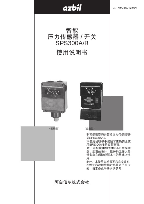
智能 压力傳感器/開關
SPS300A/B
使用説明書
No. CP-UM-1425C
(壁掛型)
(盤裝型)
非常感謝您購買智能壓力傳感器・開關 SPS300A・B。 本使用說明書中記述了正確安全使用本 機的必要事項。 對於承擔使用本機的操作盤、裝置的 設計、維護的工作人員請務必在閱讀 理解本書的基礎上使用。 此外,本使用說明書不只在安裝時,在 維護和故障維修時也是必不可少的。 請常備此手冊以供參考。
2. 各部分的名稱・操作方法 . . . . . . . . . . . . . . . . . . . 4 1. 操作方法一覧表 . . . . . . . . . . . . . . . . . . . . . . . .5 2. 操作方法 . . . . . . . . . . . . . . . . . . . . . . . . . . . .6 3. 顯示・參數模式的步驟 . . . . . . . . . . . . . . . . . . . . .9
電流初始化
+PARAMETER鍵 PV 値 調 整 PV零點調整
PV滿量程點調整
PV初始化
自診斷 數字顯示
KEYLOCK RELAY1 RELAY2
數
PV SP1 SP2
字
設
ENT
定
DISPALY PARAMETER
SPS300A的場合
電 流 4~20mA
輸 出
&
RELAY1 ON/OFF
繼 電
SPS300B的場合
・請務必在其他配線前,先進行保護接地端子的接線。另外,當保護接地端子的配線脫 開的場合,請務必卸掉所有其他配線後,再進行護接地端子配線的恢復。
・請務必在儀錶操作員手能夠觸及的範圍內,設置本機主電源斷電用開關。
・在本產品的主電源配線時,根據機器的供給電源電壓,配置下記的保險絲(IEC127)。 供給電源電壓 100/120VAC:類型F, 100mA, 250V 200/240VAC:類型F, 50mA, 250V
1
⑨ 濾波時間常數変更 壓力急劇変動時使用,根據設定的時間常數,可抑制PV値的変動。
○10 HI/LO運行切換
可選擇繼電器的勵磁方向反向。 既,對HI設定,壓力上昇時繼電器駆動為非勵磁,下降時為勵磁。對LO設定 壓力下降時繼電器駆動為非勵磁,上昇時為勵磁。 繼電器勵磁時,動作顯示LED燈亮。
○11 PV偏置
爲避免觸電造成人身傷害的危險,請依照本使用說明書中記載的所有安全注意 事項進行操作。 此符號用於警示用戶有因觸摸而觸電的危險。
保護接地端子。為與保護接地導體連接而設計的。
・未按本公司規定的使用方法使用的場合,會損壞本機的安全保護裝置。
・請勿用本公司指定以外的部件進行更換。
・請在具有認證資格且經驗豐富的操作員的操作下,依照各個地方的規則進行所有配線 作業。
ⅰ
為了安全、正確地使用本產品
-使用上的注意事項-
警告
● 請務必切斷電源後,再進行本機的接線、安裝及拆卸作業。 不小心碰到端子等受電部時,會觸電。 ● 請可靠地實施保護接地後,再進行測定對象或外部控制回路的連接。
否則會有觸電、發生火災的危險。
注意
● 產品出廠時,已經對PV値的零點、滿量程點進行了調整,請勿再進行調整。如果有必要的場合,請 用PV偏置進行調整。
● 為了充分満足本體的性能,請按照P25~33的內容實施安裝・接線作業。 ● 請按規定的標準、使用説明書指定的纜線及施工方法,對本產品進行正確的配線。
否則有觸電、發生火災、產生故障的危險。 ● 請在允許使用條件(溫度、濕度、電壓、振動、衝撃、環境等)範囲內使用本產品。
否則有產生故障的危險。 ● 請勿分解本產品。也不要觸摸內部的部件。
器 接
RELAY 1
ON/OFF
點
&
輸 出
RELAY 2
ON/OFF
△
▽
3
2. 各部分的名稱・操作方法
ห้องสมุดไป่ตู้
繼電器1動作顯示
鍵鎖動作顯示
繼電器2動作顯示
負顯示
圧力値動作顯示 (PV値顯示)
上昇鍵 左移鍵
下降鍵
KEYLOCK RELAY1 RELAY2 PV SP1
ENT DISPALAY PARAMETER
ⅱ
1. 概 要
1. 概 要 智能壓力傳感器·開關SPS300A/B是採用固態硅半導體壓力元件的數字顯示壓
力傳感器。可用於空氣壓力、蒸氣壓力、不腐蝕金屬的液體或不燃性氣體、液體 的壓力控制、警報等。備有壁掛安裝型及盤安裝型。
2. 特 長 ① 高精度
在0~50℃狀態下,顯示及4~20mA輸出的総合精度為±0.25%FS的高精度。 不受溫度變化的影響。 ② 壓力顯示 4位7段LED顯示壓力値(PV値)。小數點的位置在最小分辨率的范围內可移動。 ③ 4~20mA輸出 把量程的全量程範圍或設定的量程範圍對應的PV値轉換成4~20mA輸出。 ④ 繼電器接點輸出 根據下項⑤的設定,執行繼電器的ON/OFF控制,以接點方式輸出。 ⑤ 數字設定(設定點、差動) 通過鍵輸入,在觀察數字顯示的同時,可輸入繼電器接點的設定點及差動值, 且必要時,也可看設定點。 ⑥ 鍵鎖 鍵鎖狀態下,也可顯示DISPLAY模式、PARAMETER模式的內容并確認,但不能 設定。所以可以防止誤設定及惡意設定。 ⑦ 顯示位変更 為了防止微少壓力変動產生的顯示抖動,可以通過變更顯示位,使下位顯示 部不顯示。 ⑧ 峰值保持 記錄到目前位置施加的最高壓力値,必要時可確認。但斷電後被清除。
(REL2)
△
△
4~20mA手動輸出 (有繼電器控制)
3. 故障處理 . . . . . . . . . . . . . . . . . . . . . . . . . . . .16 1. 報警顯示 . . . . . . . . . . .. . . . . . . . . . . . . . . . .16 2. 故障 . . . . . . . . . . . . .. . .. . . . . . . . . . . . . . 16
○○ (DI.F1)
解除 *
DIFF2値設定 數字濾波時間常數設定 PARAMETER鍵 ②參數模式 PV偏置値設定
×○ (DI.F2)
○○ (FILT)
○○ (BIAS)
* 1.000s
0
峰值保持値顯示
○○
-
(PEAK)
繼電器1繼電器運行狀態設定
○
○
HI
(REL1)
繼電器2繼電器運行狀態設定
×
○
HI
6. 接 線 . . . . . . . .. . . . . . . . . . . . . . . . . . . . . .28 7. 維 護 . . . . . . . . . . . . . . . . . . . . . . . . . . . . . 34
安全要求事項 (SAFETY REQUIREMENTS)
現在値顯示部 繼電器1的設定動作顯示 繼電器2的設定動作顯示 右移鍵
輸入鍵
顯示鍵
參數鍵
△ △
▽ ▽
▽ ▽
▽ ▽
顯示鍵時輸入數値的場合
○用 △
▽
増減。
中的一個鍵,用 鍵或 鍵進行位移動,用△或▽鍵進行數値的
○ 輸入數値時,按 ENT 鍵。
參數鍵時輸入數値的場合 ○ 輸入數値時,首先按 ENT 鍵。
○ 然後用 △ 中的一個鍵,用 或 進行位的移動,用△或▽鍵進行數値的
4. 型號構成・規格・外形尺寸圖 . . . . . . . . . . . . . . . . . 18 1. 型號構成 . . . . . . . . . . . . . . . . . . . . . . . . . . 18 2. 規 格 . . . . . . . . . . . . . . . . . . . . . . . . . . . . 19 3. 附屬品・ 選購件 . . . . . . . . . . . . . . . . . . . . . .22 4. 外形尺寸圖 . . . . . . . . . . . . . . . . . . . . . . . . . .23