HT2535 扁壳充电器BOM变压器资料
5V800mA应用手册EMI

85V 115V 230V 265V High limit Low limit
5.7. 短路与释放 Protection Pin (W)
85 VAC 0.008
Release 85 VAC, 0% Po(W) 85 VAC, 100% Po(W) 265 VAC, 0% Po(W) 265 VAC, 100% Po(W)
0% Po 0
25% Po 200
Po(W)
0.00
1.00
85
5.186
5.009
115
5.191
5.003
230
5.194
4.993
265
5.194
4.961
50% Po 400 2.00 5.008 4.995 4.985 4.980
AC/DC 系列 2535 5V/800mA
75% Po 600 3.00 5.021 5.006 4.998 4.988
数量 1 1 1 1 1 1 1 1 1 1 1 1 2 1 1 1 1 1 1 1 4 1 1 1 1 1 1
-3-
韩方栋 15800731464
4. 变压器规格
4.1. 示意图
AC/DC 系列 2535 5V/800mA
变压器示意图
4.2. 材料清单
绕组
脚位
开始
结束
匝数
类型
绝缘导线/铜箔 线径/数量
25% Po 1
200 75.75% 70.42%
115
230
265
Input Voltage (VAC)
50% Po 2
400 74.62% 72.63%
75% Po 3
T2535-800G中文资料

1/9®BTA/BTB24,BTA25,BTA26and T25SeriesSNUBBERLESS ™&STANDARD25A TRIAC SSeptember 2000-Ed:3MAIN FEATURES:DESCRIPTIONAvailable either in through-hole of surface and T25mount packages,the BTA/BTB24-25-26triac series is suitable for general purpose AC power switching.They can be used as an ON/OFF function in applications such as static relays,heating regulation,water heaters,induction motor starting circuits...or for phase control operation in high power motor speed controllers,soft start circuits...The snubberless versions (BTA/BTB...W and T25series)are specially recommended for use on inductive loads,thanks to their high commutation performances.By using an internal ceramic pad,the BTA series provides voltage insulated tab (rated at 2500V RMS)complying with UL standards (File ref.:E81734).Symbol Value Unit I T(RMS)25A V DRM /V RRM 600and 800V I GT (Q 1)35to 50mAABSOLUTE MAXIMUM RATINGSSymbol ParameterValueUnit I T(RMS)RMS on-state current (full sine wave)D P AK TO-220AB Tc =100°C 25ARD91TOP3Ins.Tc =90°C TO-220AB Ins.Tc =75°C I TSM Non repetitive surge peak on-state current (full cycle,Tj initial =25°C)F =60Hz t =16.7ms 260A F =50Hzt =20ms250I t I t Value for fusingtp =10ms450A s dI/dtCritical rate of rise of on-state current I G =2x I GT ,tr ≤100nsF =120Hz Tj =125°C 50A/µs V DSM /V RSM Non repetitive surge peak off-statevoltagetp =10ms Tj =25°C V DRM /V RRM+100V I GM Peak gate currenttp =20µsTj =125°C 4A P G(AV)Average gate power dissipation Tj =125°C1W T stg T jStorage junction temperature range Operating junction temperature range-40to +150-40to +125°C GA2A1GA2A2A1GA2A2A1TO-220AB (BTB24)TO-220AB Insulated (BTA24)TOP3Insulated (BTA26)A1A2GA2A2GA1A2A1GD 2PAK (T25G)RD91(BTA25)BTA/BTB24,BTA25,BTA26and T25Series2/9ELECTRICAL CHARACTERISTICS (Tj =25°C,unless otherwise specified)sSNUBBERLESS ™(3Quadrants)T25-G,BTA/BTB24...W,BTA25...W,BTA26...WsSTANDARD (4Quadrants):BTA25...B,BTA26...BSTATIC CHARACTERISTICSNote 1:minimum IGT is guaranted at 5%of IGT max.Note 2:for both polarities of A2referenced to A1Symbol Test ConditionsQuadrantT25BTA/BTB UnitT2535CW BW I GT (1)V D =12V R L =33ΩI -II -III MAX.353550mA V GT I -II -III MAX. 1.3V V GD V D =V DRM R L =3.3k ΩTj =125°CI -II -IIIMIN.0.2V I H (2)I T =500mA MAX.505075mA I L I G =1.2I GTI -III MAX.707080mA II8080100dV/dt (2)V D =67%V DRM gate open Tj =125°CMIN.5005001000V/µs (dI/dt)c (2)Without snubberTj =125°CMIN.131322A/msSymbol Test ConditionsQuadrant Value Unit I GT (1)V D =12VR L =33ΩI -II -III IV MAX.50100mA V GT ALL MAX. 1.3V V GD V D =V DRM R L =3.3k ΩTj =125°CALLMIN.0.2V I H (2)I T =500mA MAX.80mA I L I G =1.2I GTI -III -IVMAX.70mAII160dV/dt (2)V D =67%V DRM gate open Tj =125°CMIN.500V/µs (dV/dt)c (2)(dI/dt)c =13.3A/msTj =125°CMIN.10V/µs Symbol Test ConditionsValue Unit V TM (2)I TM =35Atp =380µsTj =25°C MAX. 1.55V V to (2)Threshold voltage Tj =125°C MAX.0.85V R d (2)Dynamic resistance Tj =125°C MAX.16m ΩI DRM I RRMV DRM =V RRMTj =25°C MAX.5µA Tj =125°C3mABTA/BTB24,BTA25,BTA26and T25Series3/9THERMAL RESISTANCESS:Copper surface under tabPRODUCT SELECTORBTB:Non insulated TO-220AB packageORDERING INFORMATIONSymbol ParameterValue Unit R th(j-c)Junction to case (AC)D PAK TO-220AB 0.8°C/WRD91(Insulated)TOP3Insulated 1.1TO-220AB Insulated1.7R th(j-a)Junction to ambientS =1cmD PAK 45°C/WTOP3Insulated 50TO-220AB 60TO-220AB InsulatedPart NumberVoltage (xxx)SensitivityType Package 600V800V BTB24-xxxB X X 50mA Standard TO-220AB BTA/BTB24-xxxBW X X 50mA Snubberless TO-220AB BTA/BTB24-xxxCW X X 35mA Snubberless TO-220AB BTA25-xxxB X X 50mA Standard RD-91BTA25-xxxBW X X 50mA Snubberless RD-91BTA25-xxxCW X X 35mA Snubberless RD-91BTA26-xxxB X X 50mA Standard TOP3Ins.BTA26-xxxBW X X 50mA Snubberless TOP3Ins.BTA26-xxxCW X X 35mA Snubberless TOP3Ins.T2535-xxxGXX35mASnubberlessDPAK BT A 24-600BWTRIAC SERIES INSULATION:A:insulatedB:non insulatedCURRENT:24:25A in TO-220AB 25:25A in Rd9126:25A in TOP3SENSITIVITY &TYPE B:50mA STANDARDBW:50mA SNUBBERLESS CW:35mA SNUBBERLESSVOLTAGE:600:600V 800:800VBTA/BTB24,BTA25,BTA26and T25Series4/9OTHER INFORMATIONNote :xxx=voltage,y =sensitivity,z =typePart NumberMarkingWeight Base quantity Packing mode BTA/BTB24-xxxyz BTA/BTB24xxxyz 2.3g 250Bulk BTA25-xxxyz BTA25xxxyz 20g 25Bulk BTA26-xxxyz BTA26xxxyz 4.5g 120Bulk T2535-xxxG T2535xxxG 1.5g 50Tube T2535-xxxG-TRT2535xxxG1.5g1000Tape &reelT 2535-600G(-TR)TRIAC SERIES SENSITIVITY:35:35mAVOLTAGE:600:600V 800:800VCURRENT:25APACKAGE:G:D PAK2PACKING MODE:Blank:Tube-TR:Tape &ReelBTA/BTB24,BTA25,BTA26and T25Series5/9Fig.1:Maximum power dissipation versus RMS on-state current (full cycle).Fig.2-1:RMS on-state current versus case temperature (full cycle).Fig.2-2:D P AK RMS on-state current versus ambient temperature (printed circuit board FR4,copper thickness:35µm),full cycle.Fig.3:Relative variation of thermal impedance versus pulse duration.Fig.4:On-state characteristics (maximumvalues).Fig.5:Surge peak on-state current versus number of cycles.5101520250510********IT(RMS)(A)P (W)025507510012551015202530Tc(°C)IT(RMS)(A)BTA24BTB/T25BTA25/262550751001250.00.51.01.52.02.53.03.54.0Tamb(°C)IT(RMS)(A)D PAK (S=1cm )221E-31E-21E-11E+01E+11E+25E+21E-31E-21E-11E+0tp (s)K=[Zth/Rth]Zth(j-c)Zth(j-a)BTA/BTB24/T25Zth(j-a)BTA260.51.01.52.02.53.03.54.0 4.5110100300VTM (V)ITM (A)Tj=25°CTj maxTj max.Vto =0.85V Rd =16m Ω110100100050100150200250300Number of cyclesITSM (A)Non repetitive Tj initial=25°CRepetitive Tc=75°COne cyclet=20msBTA/BTB24,BTA25,BTA26and T25Series6/9Fig.6:Non-repetitive surge peak on-state current for a sinusoidal pulse with width tp <10ms,and corresponding value of I t.Fig.7:Relative variation of gate trigger current,holding current and latching current versus junction temperature (typical values).Fig.8:Relative variation of critical rate of decrease of main current versus (dV/dt)c (typical values).Fig.9:Relative variation of critical rate of decrease of main current versus junction temperature.Fig.10:D PAK Thermal resistance junction to ambient versus copper surface under tab (printed circuit board FR4,copper thickness:35µm).0.010.101.0010.0010010003000tp (ms)ITSM (A),I t (A s)Tj initial=25°CITSMI tdI/dt limitation:50A/µs-40-20204060801001201400.00.51.01.52.02.5Tj(°C)IGT,IH,IL[Tj]/IGT,IH,IL[Tj=25°C]IGTIH &IL0.11.010.0100.00.40.60.81.01.21.41.61.82.02.22.4(dV/dt)c (V/µs)(dI/dt)c [(dV/dt)c]/Specified (dI/dt)cBW/CW/T2535B2550751001250123456Tj (°C)(dI/dt)c [Tj]/(dI/dt)c [Tj specified]4812162024283236401020304050607080S(cm )Rth(j-a)(°C/W)D PAKBTA/BTB24,BTA25,BTA26and T25Series7/9PACKAGE MECHANICAL DATA D PAK (Plastic)REF.DIMENSIONSMillimeters Inches Min.Typ.Max.Min.Typ.Max.A 4.30 4.600.1690.181A1 2.49 2.690.0980.106A20.030.230.0010.009B 0.700.930.0270.037B2 1.25 1.400.0480.055C 0.450.600.0170.024C2 1.21 1.360.0470.054D 8.959.350.3520.368E 10.0010.280.3930.405G 4.88 5.280.1920.208L 15.0015.850.5900.624L2 1.27 1.400.0500.055L3 1.40 1.750.0550.069R 0.400.016V20°8°0°8°AC2DR2.0MIN.FLAT ZONEA2V2CA1GLL3L2BB2EFOOTPRINT DIMENSIONS (in millimeters)D PAK (Plastic)8.903.701.305.0816.9010.30BTA/BTB24,BTA25,BTA26and T25Series8/9PACKAGE MECHANICAL DATA RD91(Plastic)REF.DIMENSIONSMillimeters InchesMin.Max.Min.Max.A 40.00 1.575A129.9030.30 1.1771.193A222.000.867B 27.00 1.063B113.5016.500.5310.650B224.000.945C 14.000.551C1 3.500.138C2 1.95 3.000.0770.118E30.700.900.0270.035F 4.00 4.500.1570.177I 11.2013.600.4410.535L1 3.10 3.500.1220.138L2 1.70 1.900.0670.075N133°43°33°43°N228°38°28°38°A2L2L1B2CC2A1C1B1N1BFIAE3N2PACKAGE MECHANICAL DATA TOP3(Plastic)REF.DIMENSIONSMillimeters Inches Min.Typ.Max.Min.Typ.Max.A 4.4 4.60.1730.181B 1.45 1.550.0570.061C 14.3515.600.5650.614D 0.50.70.0200.028E 2.7 2.90.1060.114F 15.816.50.6220.650G 20.421.10.8150.831H 15.115.50.5940.610J 5.4 5.650.2130.222K 3.4 3.650.1340.144L 4.08 4.170.1610.164P 1.201.400.0470.055R4.600.181BTA/BTB24,BTA25,BTA26and T25Series9/9PACKAGE MECHANICAL DATA TO-220AB (Plastic)REF.DIMENSIONSMillimeters Inches Min.Typ.Max.Min.Typ.Max.A 15.2015.900.5980.625a1 3.750.147a213.0014.000.5110.551B 10.0010.400.3930.409b10.610.880.0240.034b2 1.23 1.320.0480.051C 4.40 4.600.1730.181c10.490.700.0190.027c2 2.40 2.720.0940.107e 2.40 2.700.0940.106F 6.20 6.600.2440.259I 3.75 3.850.1470.151I415.8016.4016.800.6220.6460.661L 2.65 2.950.1040.116l2 1.14 1.700.0440.066l3 1.14 1.700.0440.066M2.600.102MBl4Cb2a2l2c2l3b1a1AFLIec1Information furnished is believed to be accurate and reliable.However,STMicroelectronics assumes no responsibility for the consequences of use of such information nor for any infringement of patents or other rights of third parties which may result from its use.No license is granted by implication or otherwise under any patent or patent rights of STMicroelectronics.Specifications mentioned in this publication are subject to change without notice.This publication supersedes and replaces all information previously supplied.STMicroelectronics products are not authorized for use as critical components in life support devices or systems without express written approval of STMicroelectronics.©The ST logo is a registered trademark of STMicroelectronics ©2000STMicroelectronics -Printed in Italy -All Rights ReservedSTMicroelectronics GROUP OF COMPANIESAustralia -Brazil -China -Finland -France -Germany -Hong Kong -India -Italy -Japan -Malaysia -Malta -MoroccoSingapore -Spain -Sweden -Switzerland -United Kingdom。
bp2535c电路的变压器设计

bp2535c电路的变压器设计我们需要了解变压器的基本原理。
变压器是一种通过电磁感应原理将交流电能传递给另一个电路的装置。
它由一个或多个线圈组成,这些线圈通过铁芯连接。
在变压器中,输入线圈称为主线圈,输出线圈称为副线圈。
当主线圈上的电流变化时,它会在铁芯中产生一个交变磁场,从而在副线圈中感应出电流。
通过调整主线圈和副线圈的匝数比例,我们可以改变输入电压和输出电压之间的关系。
在设计bp2535c电路的变压器时,我们首先需要确定所需的输入电压和输出电压。
根据电路的要求,我们可以选择合适的输入电压和输出电压范围。
然后,我们可以根据所选电压范围来确定主线圈和副线圈的匝数比例。
通常情况下,主线圈的匝数与副线圈的匝数成正比,即匝数比等于输出电压与输入电压之比。
例如,如果我们需要将输入电压从220V降低到110V,那么我们可以选择一个匝数比为1:2的变压器。
接下来,我们需要选择合适的铁芯材料和尺寸。
铁芯的材料应具有高导磁性能和低磁滞损耗,以确保变压器的效率和稳定性。
常见的铁芯材料有硅钢片和铁氧体。
硅钢片具有较高的导磁性能和低磁滞损耗,适用于频率低于1kHz的应用。
铁氧体则适用于高频应用,具有较低的损耗和较高的饱和磁感应强度。
根据电路的工作频率和功率要求,我们可以选择合适的铁芯材料。
除了铁芯材料,铁芯的尺寸也非常重要。
变压器的效率和功率容量取决于铁芯的尺寸。
通常情况下,铁芯的截面积越大,变压器的功率容量越大。
然而,过大的铁芯会增加变压器的成本和体积。
因此,在设计中需要在功率容量和成本之间进行平衡。
我们还需要考虑变压器的绕组和绝缘设计。
绕组的电阻和电感对变压器的效率和稳定性有很大影响。
绕组的电阻应尽量小,以减少功率损耗。
绕组的电感应保持在合适的范围内,以避免过大的电感引起的共振和损耗。
在设计变压器电路时,我们还需要考虑其他因素,如温度和散热问题。
变压器在工作过程中会产生一定的热量,如果不能及时散热,可能会导致温度升高,影响变压器的性能和寿命。
半导体中频变压器参数表

半导体中频变压器参数表
【实用版】
目录
一、半导体中频变压器的概念与作用
二、半导体中频变压器的分类与型号
三、半导体中频变压器的参数及其含义
四、如何选择半导体中频变压器
五、使用半导体中频变压器的注意事项
正文
一、半导体中频变压器的概念与作用
半导体中频变压器是一种用于半导体收音机、电视机等电子设备中的电子元器件,主要作用是在信号处理过程中对中频信号进行变换和放大。
通过变换和放大中频信号,可以提高电子设备的接收性能和信号质量。
二、半导体中频变压器的分类与型号
半导体中频变压器有很多分类和型号,常见的分类有调频、调幅收音机用的中频变压器,彩色电视机用的中频变压器等。
其中,调频收音机的中频变压器有 TP-11、TP-12、TP-13、TP-06、WTP-07、TP-08、TP-09 等型号;调幅收音机的中频变压器有 TTF-1、TTF-2、BZX-19、BZX-20、SZP1、SZP2 等型号;彩色电视机用的中频变压器有 1OKR3744、1OKRC3706、
1OKRC3707、1SlOTCO1 等型号。
三、半导体中频变压器的参数及其含义
半导体中频变压器的参数主要包括工作频率、额定功率、电压等。
这些参数决定了中频变压器的使用范围和性能。
例如,工作频率决定了中频变压器适用的信号范围;额定功率决定了中频变压器能承受的最大功率;电压则决定了中频变压器的输入和输出电压范围。
四、如何选择半导体中频变压器
选择半导体中频变压器时,首先要根据设备的需要确定所需的型号和参数;其次要考虑中频变压器的性能,如工作稳定性、抗干扰能力等;最后还要考虑中频变压器的价格和可靠性。
5V 1A 充电器 变压器文件
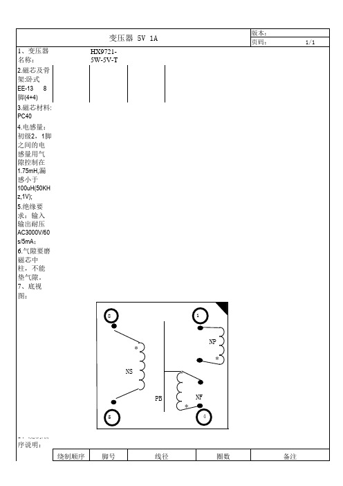
2.磁芯及骨 架:卧式 EE-13 8 脚(4+4)
3.磁芯材料: PC40
4.电感量: 初级2,1脚 之间的电 感量用气 隙控制在 1.75mH,漏 感小于 100uH(50KH z,1V);
5.绝缘要 求:输入 输出耐压 AC3000V/60 s/5mA; 6.气隙要磨 磁芯中 柱,不能 垫气隙。
便 于插印板 进识别。
3、对 未绕满一 层的线圈 要绕在变 压器骨架 的中间, 最好用挡 墙加以保 证。
编制: 审定: 批准:
Φ0.13 Φ0.5 Φ0.18
135T 9T 29T
设计人: 品质: 日期:
三重绝缘线
7、底视 图:
变压器 5V 1A
HX97215W-5V-T
8
1
版本:页码:1/1 NhomakorabeaNP *
* NS
8、绕制顺 序说明:
绕制顺序
5
脚号
PB
NF
*
4
线径
圈数
备注
1、NP
2
1
2、NS
8
5
3、NF
4
3
9、注: 1、按
上述耐压 要求,配 相应绝缘 材料,如挡 墙,耐高 温绝缘套 管等。2、绕 制的变压 器标签为 HX97215W-5VT,标签对 应1脚处加 “*”标 识,
MR2535L中文资料

Figure 1. Surge Current Characteristics
2
Rectifier Device Data
元器件交易网
PACKAGE DIMENSIONS
MR2535L MR2535S
A D
1 NOTES: 1. CATHODE SYMBOL ON PACKAGE. DIM A B D E MILLIMETERS MIN MAX 8.43 8.69 5.94 6.25 1.27 1.35 25.15 25.65 INCHES MIN MAX 0.332 0.342 0.234 0.246 0.050 0.053 0.990 1.010
元器件交易网
MOTOROLA
SEMICONDUCTOR TECHNICAL DATA
Order this document by MR2535L/D
Advance Information Overvoltage Transient Suppressors
. . . designed for applications requiring a low voltage rectifier with reverse avalanche characteristics for use as reverse power transient suppressors. Developed to suppress transients in the automotive system, these devices operate in the forward mode as standard rectifiers or reverse mode as power avalanche rectifier and will protect electronic equipment from overvoltage conditions. • • • • Avalanche Voltage 24 to 32 Volts High Power Capability Economical Increased Capacity by Parallel Operation
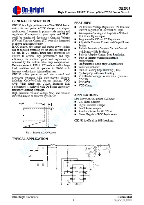
昂宝-OB2535规格书
MBr i d e ch n ol o gy Co .,Lt d .OB2535High Precision CC/CV Primary-Side PWM Power SwitchGENERAL DESCRIPTIONOB2535 is a high performance offline PWM Power switch for low power AC/DC charger and adaptor applications. It operates in primary-side sensing and regulation. Consequently, opto-coupler and TL431 could be eliminated. Proprietary Constant Voltage (CV) and Constant Current (CC) control is integrated as shown in the figure below.In CC control, the current and output power setting can be adjusted externally by the sense resistor Rs at CS pin. In CV control, multi-mode operations are utilized to achieve high performance and high efficiency. In addition, good load regulation is achieved by the built-in cable drop compensation. Device operates in PFM in CC mode as well at large load condition and it operates in PWM with frequency reduction at light/medium load.OB2535 offers power on soft start control and protection coverage with auto-recovery features including Cycle-by-Cycle current limiting, VDD OVP, VDD clamp and UVLO. Excellent EMI performance is achieved with On-Bright proprietary frequency shuffling technique.High precision constant voltage (CV) and constant current (CC) can be achieved by OB2535. .Fig.1. Typical CC/CV CurveFEATURES5% Constant Voltage Regulation, 5% ConstantCurrent Regulation at Universal AC input Primary-side Sensing and Regulation WithoutTL431 and Opto-couplerProgrammable CV and CC RegulationAdjustable Constant Current and Output PowerSettingBuilt-in Secondary Constant Current Controlwith Primary Side FeedbackBuilt-in Adaptive Current Peak Regulation Built-in Primary winding inductancecompensationProgrammable Cable drop Compensation Power on Soft-startBuilt-in Leading Edge Blanking (LEB) Cycle-by-Cycle Current LimitingVDD Under Voltage Lockout with Hysteresis(UVLO) VDD OVP VDD ClampAPPLICATIONSLow Power AC/DC offline SMPS for Cell Phone ChargerDigital Cameras Charger Small Power AdaptorAuxiliary Power for PC, TV etc. Linear Regulator/RCC ReplacementOB2535 is offered in SOP8 package.TYPICAL APPLICATIONM icr oBge Te ch n ol o gy Co .,Lt d .OB2535High Precision CC/CV Primary-Side PWM Power SwitchGENERAL INFORMATIONPin ConfigurationThe pin map is shown as below for SOP8VDD COMP INVCSGND GNDOrdering Information Part Number Description OB2535CP SOP8, Pb-free, Tube OB2535CPA SOP8, Pb-free, T&RPackage Dissipation Rating Package R θJA (℃/W) SOP8 90Note: Drain Pin Connected 100mm 2 PCB copper clad.Absolute Maximum RatingsParameter Value Drain Voltage (off state) -0.3V to Bvdss VDD Voltage -0.3 to V DD _clamp VDD Zener Clamp Continuous Current 10 mA COMP Voltage -0.3 to 7V CS Input Voltage -0.3 to 7V INV Input Voltage -0.3 to 7V Min/Max Operating Junction Temperature T J -20 to 150 o C Min/Max Storage Temperature T stg -55 to 150 o C Lead Temperature (Soldering, 10secs) 260 o CNote: Stresses beyond those listed under “absolute maximum ratings” may cause permanent damage to the device. These are stress ratings only, functional operation of the device at these or any other conditions beyond those indicated under “recommended operating conditions” is not implied. Exposure to absolute maximum-rated conditions for extended periods may affect device reliability.M ic r oBr id ge Te ch nol o gy Co .,Lt d .OB2535High Precision CC/CV Primary-Side PWM Power SwitchMarking InformationOB2535CP YWWSC:SOP8 Package P:Pb-free Package Y:Year Code(0-9)WW:Week Code(01-52)S:Internal Code(Optional)TERMINAL ASSIGNMENTSPin Num Pin Name I/O Description 1 VDD P Power Supply 2 COMP I Loop Compensation for CV Stability3 INV I The voltage feedback from auxiliary winding. Connected to resistor dividerfrom auxiliary winding reflecting output voltage. PWM duty cycle isdetermined by EA output and current sense signal at pin 4.4 CS I Current sense input5/6 DRAIN OHV MOSFET Drain Pin. The Drain pin is connected to the primary lead ofthe transformer7/8 GND P GroundOUTPUT POWER TABLE230VAC±15% 85-264VAC Product Adapter 1 Adapter 1OB2535 6W 5WNotes:1.Maximum practical continuous power in an Adapter design with sufficient drain pattern as a heat sink, at 50℃ ambient.M ic r oBr i d geBLOCK DIAGRAMM ic r oBr i d ge Te ch n ol o gy Co .,Lt d .ELECTRICAL CHARACTERISTICS(T A = 25O C, VDD=VDDG=16V, if not otherwise noted)Symbol Parameter Test Conditions Min Typ Max UnitSupply Voltage (VDD) Section I DD ST Standby Current VDD=13V5 20uA I DD op Operation CurrentOperation supply current INV=2V, CS=0V,VDD=VDDG=20V- 2.5 3.5 mAUVLO(ON) VDD Under Voltage Lockout Enter VDD falling 7.5 8.5 10V UVLO(OFF) VDD Under Voltage Lockout Exit VDD rsing13.5 14.5 16.0V V DD _clamp Maximum VDD operationvoltageI DD =10mA30.5 32.5 34.5V OVPOver voltage protection ThresholdRamp VDD until gate shut down27.5 29.5 31.5V Current Sense Input SectionTLEB LEB time540 ns Vth_oc Over current threshold870 900 930 mVTd_oc OCP Propagation delay150 ns Z SENSE _IN Input Impedance50 KohmT_ssSoft start time10msFrequency SectionFreq_Max Note 1 IC Maximum frequency66 72 78 KHzFreq_NomSystem Nominal switch frequency60KHzFreq_startup INV =0V, Comp =5V 14 KHz △f/FreqFrequency shuffling range+/-4% Error Amplifier section Vref_EA Reference voltage for EA 1.972 2.03 V GainDC gain of EA60 dB I_COMP_MAXMax. Cable compensationcurrentINV=2V, Comp=0V42uAPower MOSFET Section BVdss MOSFET Drain-Source Breakdown Voltage 600 V RdsonOn ResistanceStatic, Id=0.4A1215ΏNote:1. Freq_Max indicates IC internal maximum clock frequency. In system application, the maximum operation frequency of 60Khz nominal occurs at maximum output power or the transition point from CV to CC.M ic r oBr i d g e T en t CHARACTERIZATION PLOTSM ic r oBr i d ge Te c.,Lt d .OPERATION DESCRIPTIONOB2535 is a cost effective PWM power switch optimized for off-line low power AC/DC applications including battery chargers and adaptors. It operates in primary side sensing and regulation, thus opto-coupler and TL431 are not required. Proprietary built-in CV and CC control can achieve high precision CC/CV control meeting most adaptor and charger application requirements.z Startup Current and Start up ControlStartup current of OB2535 is designed to be very low so that VDD could be charged up above UVLO threshold and starts up quickly. A large value startup resistor can therefore be used to minimize the power loss in application.z Operating CurrentThe Operating current of OB2535 is as low as 2.5mA. Good efficiency is achieved with the low operating current together with ‘Muti-mode’ control features.z Soft StartOB2535 features an internal soft start to minimize the component electrical over-stress during power on startup. As soon as VDD reaches UVLO (OFF), the control algorithm will ramp peak current voltage threshold gradually from nearly zero to normal setting of 0.90V. Every restart is a soft start.z CC/CV OperationOB2535 is designed to produce good CC/CV control characteristic as shown in the Fig. 1.In charger applications, a discharged battery charging starts in the CC portion of the curve until it is nearly full charged and smoothly switches to operate in CV portion of the curve.In an AC/DC adapter, the normal operation occurs only on the CV portion of the curve. The CC portion provides output current limiting. In CV operation, the output voltage is regulated through the primary side control. In CC operation mode, OB2535 will regulate the output current constant regardless of the output voltage drop.z Principle of OperationTo support OB2535 proprietary CC/CV control, system needs to be designed in DCM mode for flyback system (Refer to Typical Application Diagram on page1).In the DCM flyback converter, the output voltage can be sensed via the auxiliary winding. During MOSFET turn-on time, the load current is supplied from the output filter capacitor Co. The current inthe primary winding ramps up. When MOSFET turns off, the primary current transfers to the secondary at the amplitude ofP SPS I N N I ⋅=(1) The auxiliary voltage reflects the output voltage as shown in fig.2 and it is given by)(V V N N V O SAUXAUX Δ+⋅=(2) Where ΔV indicates the drop voltage of the output Diode.Fig.2. Auxiliary voltage waveformVia a resistor divider connected between the auxiliary winding and INV (pin 3), the auxiliary voltage is sampled at the end of the de-magnetization and it is hold until the next sampling. The sampled voltage is compared with Vref (2.0V) and the error is amplified. The error amplifier output COMP reflects the load condition and controls the PWM switching frequency to regulate the output voltage, thus constant output voltage can be achieved.When sampled voltage is below Vref and the error amplifier output COMP reaches its maximum, the switching frequency is controlled by the sampled voltage thus the output voltage to regulate the output current, thus the constant output current can be achieved.z Adjustable CC point and Output PowerIn OB2535, the CC point and maximumoutput power can be externally adjusted by external current sense resistor Rs at CS pin as illustrated in Typical Application Diagram. The output power is adjusted through CC point change. The larger Rs, the smaller CC point is, and the smaller output power becomes, and vice versa as shown in Fig.3.M ic r oBr i d ge Te ch n ol o gy Co .,Lt d .Fig.3 Adjustable output power by changing Rsz Operation switching frequencyThe switching frequency of OB2535 is adaptively controlled according to the load conditions and the operation modes. No external frequency setting components are required. The operation switching frequency at maximum output power is set to 60K Hz internally.For flyback operating in DCM, The maximum output power is given by221pSW P MAX I F L Po =(3) Where Lp indicate the inductance of primary winding and Ip is the peak current of primary winding.Refer to the equation 3, the change of the primary winding inductance results in the change of the maximum output power and the constant output current in CC mode. To compensate the change from variations of primary winding inductance, the switching frequency is locked by an internal loop such that the switching frequency isDemagSW T F 21=(4)Since T Demag is inversely proportional to the inductance, as a result, the product Lp and fsw is constant, thus the maximum output power and constant current in CC mode will not change as primary winding inductance changes. Up to +/-10% variation of the primary winding inductance can be compensated.z Frequency shuffling for EMI improvement The frequency shuffling (switching frequency modulation) is implemented in OB2535. The oscillation frequency is modulated so that the tone energy is spread out. The spread spectrum minimizes the conduction band EMI and therefore eases the system design.z Gate DriveThe internal power MOSFET in OB2535 is driven by a dedicated gate driver for power switch control. Too weak the gate drive strength results in higher conduction and switch loss of MOSFET while too strong gate drive compromises EMI.A good tradeoff is achieved through the built-in totem pole gate design with right output strength control.z Programmable Cable drop CompensationIn OB2535, cable drop compensation is implemented to achieve good load regulation. An offset voltage is generated at INV by an internal current flowing into the resister divider. The current is inversely proportional to the voltage across pin COMP, as a result, it is inversely proportional to the output load current, thus the drop due to the cable loss can be compensated. As the load current decreases from full-load to no-load, the offset voltage at INV will increase. It can also be programmed by adjusting the resistance of the divider to compensate the drop for various cable lines used.z Protection ControlGood power supply system reliability is achieved with its rich protection features including Cycle-by-Cycle current limiting (OCP), VDD clamp, Power on Soft Start, and Under Voltage Lockout on VDD (UVLO).VDD is supplied by transformer auxiliary winding output. The output of OB2535 is shut down when VDD drops below UVLO (ON) limit and Switcher enters power on start-up sequence thereafter.M ic r oBr i d ge Te ch n ol o gy Co .,Lt d .PACKAGE MECHANICAL DATADimensions In Millimeters Dimensions In InchesSymbolMin Max Min MaxA 1.350 1.750 0.053 0.069 A1 0.050 0.250 0.002 0.010 A2 1.250 1.650 0.049 0.065 b 0.310 0.510 0.012 0.020 c 0.170 0.250 0.006 0.010D 4.700 5.150 0.185 0.203E 3.800 4.000 0.150 0.157 E1 5.800 6.200 0.228 0.244 e 1.270 (BSC) 0.05 (BSC)L 0.400 1.270 0.016 0.050 θ 0º 8º 0º 8º。
PS2535 Datasheet

GENERAL INFORMATION
Pin Configuration
The pin map is shown as below for SOP8
Top View
Pins Description
Pin Num
1 2 3
Pin Name
VDD COMP INV
I/O P I
Description Power Supply Loop Compensation for CV Stability The Voltage feedback from auxiliary winding. Connected to resistor divider
Under Voltage Lockout with hysteresis (UVLO) Under Voltage Lockout with
universal AC input.
Primary-side
sensing and regulation without
TL431 and Opto-coupler.
hysteresis (UVLO)
Programmable CV and CC regulation Built-in
secondary constant current control with primary side feedback.
VDD OVP VDD clamp
Built-in adaptive current peak regulation . Built-in
primary winding inductance compensation