ecelec2010
ECE和EEC(EC)汽车技术法规介绍
ECE和EEC(EC)汽车技术法规介绍ECE和EEC(EC)汽车技术法规介绍一、ECE汽车技术法规介绍1 ECE汽车技术法规及其目前的体系结构WP29(世界车辆法规论坛)目前同时运作《1958年协定书》(目前该协定书修订版的全称为《关于对轮式车辆、安装和/或用于轮式车辆的装备和部件采用统一技术法规以及采用统一条件以相互承认基于上述技术法规的批准的协定书》)和《1998年协定书》(目前该协定书全称为《关于对轮式车辆、安装和/或用于轮式车辆的装备和部件制定全球性技术法规协定书》),进行ECE汽车技术法规和全球统一汽车技术法规的制修订和实施工作。
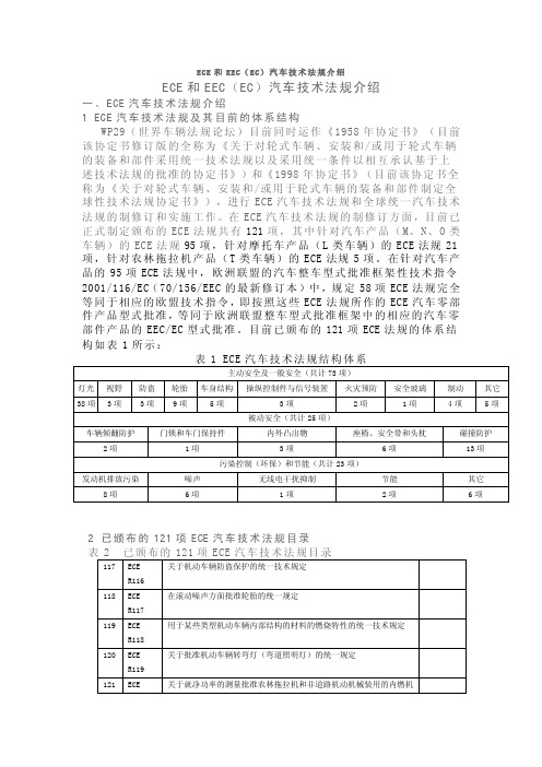
在ECE汽车技术法规的制修订方面,目前已正式制定颁布的ECE法规共有121项,其中针对汽车产品(M、N、O类车辆)的ECE法规95项,针对摩托车产品(L类车辆)的ECE法规21项,针对农林拖拉机产品(T类车辆)的ECE法规5项。
在针对汽车产品的95项ECE法规中,欧洲联盟的汽车整车型式批准框架性技术指令2001/116/EC(70/156/EEC的最新修订本)中,规定58项ECE法规完全等同于相应的欧盟技术指令,即按照这些ECE法规所作的ECE汽车零部件产品型式批准,等同于欧洲联盟整车型式批准框架中的相应的汽车零部件产品的EEC/EC型式批准。
目前已颁布的121项ECE法规的体系结构如表1所示:2 已颁布的121项ECE汽车技术法规目录注:备注栏中“等同EC指令”表示该ECE法规在2001/116/EC中被规定与相应的欧盟技术指令完全等同;“▲”表示该ECE法规为摩托车、轻便摩托车法规项目;“○”表示该ECE法规为农林拖拉机法规项目。
二、EEC(EC)汽车技术法规介绍1、前言欧洲联盟所制定的EEC(EC)技术指令(即欧洲经济共同体技术指令,由原欧洲经济共同体——EEC制定,《马斯特里赫特条约》生效实施后,EEC指令逐渐改称EC指令——欧洲共同体指令)是根据《罗马条约》针对国民经济中各种有关安全、环保、节能的产品而制定的,与联合国欧洲经济委员会的ECE汽车技术法规不同,EEC(EC)技术指令涉及国民经济的各行各业,有关车辆产品的EEC(EC)技术指令只是其中的一部分。
欧盟2010标准

欧盟2010标准
摘要:
一、欧盟2010 标准背景介绍
1.制定目的
2.适用范围
二、2010 标准的主要内容
1.排放标准
2.节能要求
3.环保材料使用
4.回收利用与废弃物处理
三、我国企业应对欧盟2010 标准的方法
1.技术升级
2.产品设计创新
3.环保意识的提高
四、欧盟2010 标准对我国产业发展的影响
1.促进产业升级
2.提高国际竞争力
3.推动环保产业发展
正文:
欧盟2010 标准是欧盟针对家电产品制定的环保标准,旨在降低家电产品对环境的影响,提高能源效率,并推广环保材料的使用。
该标准于2010 年正
式实施,对我国出口到欧盟的家电产品产生了重大影响。
为了达到2010 标准的要求,我国企业积极进行技术升级,改进生产工艺,降低产品排放。
在产品设计方面,企业注重绿色设计,提高产品能源效率,减少能源消耗。
此外,企业还加强了环保意识的培训,提高员工的环保素质,确保产品在生产、运输、使用和废弃处理等全过程中都符合环保要求。
欧盟2010 标准对我国产业发展产生了积极的推动作用。
首先,该标准促使我国企业进行产业升级,提高产品质量,增强国际竞争力。
其次,企业应对2010 标准的过程中,不断研发新技术、新产品,推动了我国环保产业的发展。
最后,2010 标准的实施,有助于提高全民的环保意识,推动我国绿色经济的发展。
总之,欧盟2010 标准对我国产业发展产生了深远的影响,促使我国企业提高环保意识,加大技术研发力度,推动产业升级。
LABView2010版讲义-1
LabVIEW2010版讲义宋湛华(Songzhanhua@)一、基本概念LabVIEW:Laboratory Virtual Instrument Engineering Workbench,一种用图标代替文本行创建应用程序的图形化编程语言。
LabVIEW用图标表示函数,用连线表示数据流向。
即用数据流编程方式,在程序框图中节点之间的数据流向决定了程序的执行顺序。
而传统的文本编程语言是根据语句和指令的先后顺序决定程序的执行顺序。
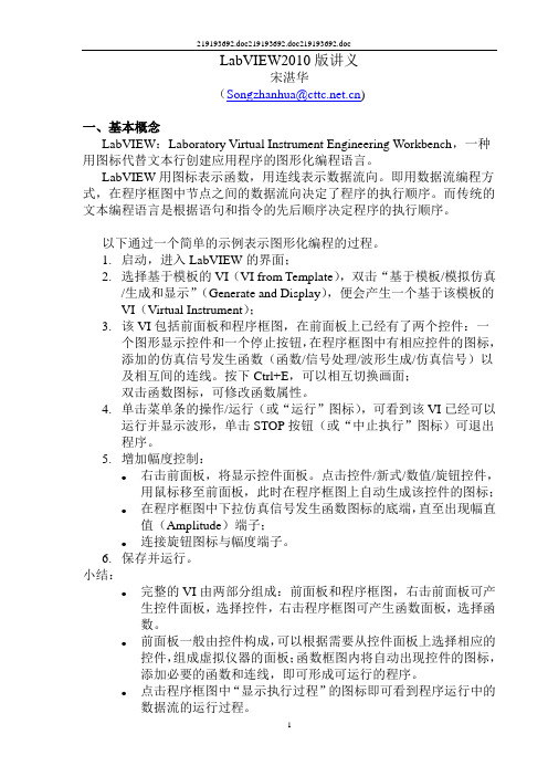
以下通过一个简单的示例表示图形化编程的过程。
1.启动,进入LabVIEW的界面;2.选择基于模板的VI(VI from Template),双击“基于模板/模拟仿真/生成和显示”(Generate and Display),便会产生一个基于该模板的VI(Virtual Instrument);3.该VI包括前面板和程序框图,在前面板上已经有了两个控件:一个图形显示控件和一个停止按钮,在程序框图中有相应控件的图标,添加的仿真信号发生函数(函数/信号处理/波形生成/仿真信号)以及相互间的连线。
按下Ctrl+E,可以相互切换画面;双击函数图标,可修改函数属性。
4.单击菜单条的操作/运行(或“运行”图标),可看到该VI已经可以运行并显示波形,单击STOP按钮(或“中止执行”图标)可退出程序。
5.增加幅度控制:●右击前面板,将显示控件面板。
点击控件/新式/数值/旋钮控件,用鼠标移至前面板,此时在程序框图上自动生成该控件的图标;●在程序框图中下拉仿真信号发生函数图标的底端,直至出现幅直值(Amplitude)端子;●连接旋钮图标与幅度端子。
6.保存并运行。
小结:●完整的VI由两部分组成:前面板和程序框图,右击前面板可产生控件面板,选择控件,右击程序框图可产生函数面板,选择函数。
●前面板一般由控件构成,可以根据需要从控件面板上选择相应的控件,组成虚拟仪器的面板;函数框图内将自动出现控件的图标,添加必要的函数和连线,即可形成可运行的程序。
小型熔断器分标委2010年会暨标准审查会召开

2 1 年 工作 计划 ,会议上进 行了讨论并 0 1 达成 了一 致意见 。吴 国平主任委 员还对
21 0 0年 国 内 外 标 准 化 工 作 的 一 些 变 化 和 发 展 做 了介 绍 和 分 析 ,要 求 分 标 委 会 应
提 案 也 获 得 了 IC 的正 式 立 项 。 E
小型熔 断器 分标委 2 1 0 0年会 暨
标 准 审查 会 召开
家和特邀代表共 3 3人参加 了会议 。 会 上 ,吴 国平 主任委员 向与会代表 作 了 2 1 分 标委 工 作总 结报 告 以及 0 0年
全 国熔 断器标准化技术 委员会小型 熔 断器分技术委员会 ( A /C 4 /C S CT 30S 3)
一 标 准 检测 认 证 ・日用 电器
全 国旋标委小功率 电机分标委会
21 0 0年 年 会 召 开
书处 提 出 的 2 1 年标 准制 修订 项 目计 01
划 ,代表们讨 论并通 过。
全 国旋转 电机标准化技 术委员会小 功率 电 机分 技术 委 员会 2 1 年 会 于 0 0年 l 0月 2 8日 ~ O臼在 上海 召 开。 中国 电 3 器院副 院长 、标委会 主任委 员吴 国平 出
长期 以来 ,欧美冰箱企 业凭借技术
代表 们审 查并 通过 4项行 业标 准 :J , BI ’ 47 一 X X 《 36 X X 水泵用 小功率异 步电动机 技 术条件 》、J , 9 4 一 X 《 B I 5 5 XX X 变压器 ’ 冷却 风扇用 三相异步 电动机技术要求 》 、 J/ BTXX X— X X X XX《家 用 潜 水 泵 用 罩 极 式 电 动机 技 术 条 件 》、J / XX BTX X— X X《工业 缝纫 机用 交流 永磁 同步 电 XX 动机技 术条件 》。代 表们针 对标准 的反
OECD绿色增长战略阶段性报告2010英文版

Box 1. Contribution of the Green Growth Strategy ................................. 14 Box 2. Progress on key environmental challenges.................................. 16 Box 3. Environmental externalities and market failures ....................... 19 Box 4. Key pillars for pro-poor Green Growth ......................................... 25 Box 5. Employment potential of green components of stimulus packages – some examples ........................................................................ 27 Box 6. The scope for moving forward public infrastructure investment .................................................................................................... 29 Box 7. Car-scrapping schemes and green growth................................... 30 Box 8. Agricultural subsidies and green growth ..................................... 35 Box 9. Examples of renewed interest in CO2-related taxes.................... 38 Box 10. Proceeds from auctioned emissions trading permits: some examples ....................................................................................................... 40 Box 11. Addressing carbon leakage and competitiveness impacts of climate policies............................................................................................. 41 Box 12. Patents and international technology transfer.......................... 47 Box 13. Transport – a growing source of CO2 emissions1 ....................... 52 Box 14. An extension of the OECD ENV-Linkages model....................... 56 Box 15. Regional and local implications of a transition towards a low-carbon economy and green growth .................................................. 58 Box 16. Key principles in selecting indicators to monitor progress with green growth........................................................................................ 62 Box II.1. The role of regulatory policy and reform .................................. 77 Box II.2. Markets and competition............................................................. 79 Box II.3. Consumer policy ........................................................................... 80 Box II.4. Responsible business conduct in support of a low carbon economy ........................................................................................................ 81 Box II.5. Taxation, innovation and the environment ............................. 82 Box II.6. “Smart” ICT applications enabling green growth .................... 84 Box II.7. Regional innovation systems for eco-innovation .................... 85 Box II.8. New models for international co-operation on ecoinnovation ..................................................................................................... 86 Box II.9. Enhancing the cost-effectiveness of biodiversity policies...... 87 Box II.10. Outcome of the February 2010 OECD Agriculture Ministerial Meeting ...................................................................................... 88 Box II.11. Relevant work for green growth measurements ................... 89
欧盟2010标准

欧盟2010标准
欧盟在2010年实施了一系列标准,涉及不同领域的产品和服务。
以下是一些2010年欧盟实施的重要标准:
1. EN 55032:2010 - 电磁兼容性(EMC)- 多媒体设备(一般构想)
该标准规定了多媒体设备的电磁兼容性要求,确保设备在使用时不会对其他设备或电网产生干扰。
2. EN 61000-6-1:2010 - 电磁兼容性(EMC)- 第6-1部分:通用标准-辐射、传导和电感耦合的工业环境
该标准规定了工业环境中各种设备的电磁兼容性要求,以确保设备在这些环境中正常工作。
3. EN 50126:2010 - 铁路应用-指定的可信任度-文件要求
该标准规定了铁路系统中可信度的要求和文件需求,以确保铁路运营的安全性和可靠性。
4. EN 12889:2010 - 燃气雇主提供的工程师培训-培训和评估
该标准规定了燃气工程师培训的要求和评估方法,
以确保工程师具备必要的知识和技能来从事燃气工程。
这些标准代表了欧盟在2010年实施的一部分,它们对欧盟市场和各个行业的产品、设备和服务起到了指导和规范作用。
需要注意的是,由于标准的更新和修订,可能会有更新版本的标准。
因此,在具体应用和遵守相关标准时,请参考最新有效的版本。
E2010电子单元说明书

MANUALE2010 ELECTRONIC UNIT FOR ZIROX- PROBESPower supply: 24 V DCTable of contents1General information 31.1How to use this manual 31.2Copyright 31.3Commonly used symbols 3 2Safety instructions 5 3Application and technical data 63.1Application 63.2Technical data 6 4Composition 84.1Front, keys 84.2Rear, connections 9 5Installation and initiation 115.1Installation 115.2Reference air supply for ZIROX® probes 115.3Waiting for operating state 11 6Parametrization 126.1Menu operation – an example 126.2Display 126.3Adjustable parameters 136.4Offset calibration 146.5Span gas calibration 146.6Reset calibration 146.7Error messages during calibration 146.8Menu navigation of calibration (diagram) 15 7Maintenance 167.1General information 167.2Calibration 167.3Error indication 167.4Storage 16 8Warranty 17 9Declaration of conformity 181 General information1.1 How to use this manualThis manual describes composition, mode of operation and use of the ELECTRONIC UNIT E2010 of the ZIROX GmbH.Proper operation of the E2010 can only be ensured if the contents of this manual are known. Therefore, all chapters of this manual must be read carefully prior to operating the E2010.The values on the device display in this manual are examples or preset parameters of the manufacturer. Process-specific parameters must be set by the user.Pages, charts and figures are numbered consecutively.1.2 CopyrightThis operation manual is copyright protected.It must not be partially or completely reproduced, copied, or distributed, without prior written permission of the manufacturer. The use for competitive advantages or the distribution to third parties are not authorized either. All rights reserved.1.3 Commonly used symbols Symbol for imminent danger:This symbol refers to imminent danger to persons’ life and health.In case of disregard fatal injuries may result.Symbol for indirect danger:This symbol indicates indirect danger.The degree of the damage depends on the circumstances and the actions of the persons involved.In case of disregard destruction or damage of the E2010, its single components or other material assets as well as minor injuries may result.dangerattentionSymbol for proper handling:This symbol appears where the manual refers to the adherence torules, instructions and proper operation.NoteIn case of disregard, damage or destruction of the E2010 or its singlecomponents may result.2 Safety instructionsThe following regulations for industrial safety provide basic informationabout potential danger during the operation of the E2010. Therefore, theymust be observed and strictly followed by the responsible staff.• A failure-free and functional operating of the E2010 can only beguaranteed with knowledge of this manual. Therefore, all chaptersof this manual must be read carefully before the installation andinitiation of the E2010.attention•The E2010 is to be used for the functional operation only (seechapter 3.1).•The E2010 may only be installed, operated, and maintained bytrained staff.•Special safety instructions for potential danger during certainworking processes are given in relevant text passages.3 Application and technical data3.1 ApplicationThe electronic unit E2010, developed for panel mounting, provides the power supply for ZIROX® sensors, evaluates signals and displays measuring results in the form of a standard signal (4-20 mA) for process control.The electronics realizes the following functions:•Power supply and control of sensor heating•Processing of the thermoelectric and cell voltage of the probe to the oxygen concentration•Output of the oxygen concentration as a standard signal•Calibration•Reference air supply by internal pump (option)3.2 Technical dataPower supply ........................................ 24 V DC +/- 10%Power consumption ............................. 2 W + sensor heating power Fuse ..................................................... 2.5 A resettingProtection degree ................................. IP 30 (Front IP52)Working temperature ............................ 0...40 °CStorage temperature ............................. 0...50°CSet temperature .................................... 700 °C (depends onconnected sensor)Display ................................................ Double-spaced LCD-display, 2 x 16 digitsInput signal ........................................... Sensor and thermoelectricvoltage (+/- 1500 mV, polarityadjustable), thermocouple typeB (400 – 1500 °C) or thermo-couple type K (0 – 1000°C)Output signal ....................................... 4...20 mA (0…10 V option)Dimensions W x H x D .......................... 96 mm x 96 mm x 125 mm Weight .................................................. Approx. 650 gKeypad ................................................ 2 keys (membrane keypad) Alarm indication ................................... Current output goes to 0 mA Interface (option) .................................. RS2324 Composition4.1 Front, keysThe display and the keys for parametrization are located on the front.Menu key: scroll or select the requested parameterENTER key: activate or enter adjusted parameter (save change)Fig. 1: Front view E2010 with keys and display4.2 Rear, connectionsAll connections and outputs are located on the rear.Fig. 2: Rear view E2010 with connections Terminal strip X1Terminal strip X2Sensor connections Power supply/output signalDigital output:………… RS 232-Interface (9600 Baud)Pin assignment RS 232The RS232 interface must be connected with a computer by SUB-D-cable (9pol., 1:1, uncrossed)!Transfer rate: max. 9600 Baud, adjustablePin Description cable 1 AINCOMbrown 2 Vz white 3 Vt blue 4 Heating+ black 5Heating-greyPin Description 1 +24V DC 2 GND 3 OUT + 4OUT -Stop bits 1 Parity no Data bits8HandshakewithoutProtocol of the serial interface (CR = carriage return)Set Feedback signal(example)Transferred measuringvalueParameterM2CR M2x.xxExxCRM22.06E+052.06*105 ppm O2Oxygen concentration inppmA1CR A1xxx.xCRA120.920.9 mV Cell voltage in mVA2CR A2xxx.xCRA2749.9749.9 °CMeasuring temperature in°CThe parameters are set by software.Additional PC-software for display and storage of the measuring values is available on request.Error messagesERROR0 Transfer error RS232 (or wrong command)ERROR1 Warm-up (Cell temperature too low, < 30 min)ERROR2 Cell temperature too low (< Set temp. – 10 °C, > 30 min) ERROR3 Thermocouple brokenERROR6 System errorElectronic unit E2010 Installation5 Installation and initiation5.1 InstallationThe clamps on the rear must be connected with the sensor clamps (s.chapter 4.2).The power supply is 24 V DC.5.2 Reference air supply for ZIROX® probesReference air input of the sensor and the reference air output of the E2010must be connected by a flexible hose (inner diameter 3 mm). The referenceair flow is preset by the manufacturer.After starting the system (E2010 with connected sensor) the reference airflow must be checked by an inserted flow meter (5 - 10 l/h resp. approx.100 - 200ml/min).5.3 Waiting for operating stateDepending on the connected sensor, the E2010 needs a certain period of Notetime until the operating state is reached (for further information seetechnical data of sensor). Because of thermal balancing effects, the sensorneeds approx. 60 minutes until the ultimate operating state after reachingthe operating temperature.The keys are locked before reaching the operating state!6 Parametrization6.1 Menu operation – an exampleAfter switch-on the warm-up starts. From 400 °C on the current temperature is displayed in the second line. After reaching the working temperature the oxygen concentration is displayed in the first line.By pressing several values can be displayed in the second line. (see chapter 6.2).With help of both keys an offset-calibration (…zero point calibration“) in clean air and a span gas calibration is possible. The complete menu is shown schematically in figure 3, p. 17.The sensor can be very hot for a while after switch-off and during operation. CAUTION – VERY HOT – DO NOT TOUCH!6.2 DisplayE2010 Start display, approx.3secVersion 2.4.6 Software versionE2010 Start display, approx.3sec THERMOCO. TYP B Thermocouple typeWARM-UP Warm-up of the ZIROX-SensorTemp: 450 °CO2: 20.64 Vol%Temp: 700 °CO2: 20.64 Vol%Vz: -2 mVO2: 20.64 Vol%SETTINGSO2: 20.64 Vol%CALIB.ZERO POINTO2: 20.64 Vol%CALIB. SPAN GAS6.3 Adjustable parametersThe following parameters are adjustable in the menu SETTINGS.OUTPUT VALUE Valid for display and analog output!Vol % O2 V ol ppm O2, mbar O2, atm O2, Vz [mV]OUTPUT VALUElog[10] linear (for Vz linear only)OUTPUT 4 - 20 mA Current outputZERO: 400 ppm Zero point 400 ppm corresponds to 4 mAOUTPUT 4 – 20 mASPAN: 206400 ppm Terminal value 206400 ppm corresponds to20 mARETURN ?NO YESSAVE VALUES ?NO YES6.4 Offset calibrationThe E2010 has a calibration function. Based on that function the zero point Notecalibration and, if requested, the span gas calibration can be conducted(see figure 3, p. 17). The zero point calibration must be conducted in cleanair.6.5 Span gas calibrationAfter calling the SPAN GAS concentration in the calibration menu (seefigure 3, p. 17), the setting options are activated by pressing the enter key.The flashing digit can be set by pressing the menu key. After changing allthe digits, this menu is deactivated by ENTER and left by the menu key.Now the calibration can be started.6.6 Reset calibrationIf in the main menu CALIB.ZERO POINT or CALIB. SPAN GAS isdisplayed and both keys are pressed for 3 seconds, RESET CAL.ZERO?and RESET CAL.SPAN respectively will be displayed.By pressing ENTER the calibration values will be reset to 0 resp. 1.6.7 Error messages during calibrationCALIBR. FAILEDOUT OF RANGE //limits: ±50mV resp.. ±50% of VzCALIBR. FAILED* TIMEOUT * //no steady measuring value in 20sec.6.8 Menu navigation of calibration (diagram)Fig. 3: Chart offset and span gas calibrationElectronic unit E2010 Maintenance7 Maintenance7.1 General informationZirox sensors and probes with thermocouple type B are calibration- andmaintenance-free. Only special products with thermocouple type K (e.g.oxygen probe SS51 for measurements in flue gases) must be calibratedperiodically.7.2 CalibrationDepending on the sensor type, a regular zero point calibration and (if sensorwith thermocouple type K) a span gas calibration is necessary (see chapter6). The corresponding frequency is outlined in the technical data of thesensor.7.3 Error indicationDuring operation the sensor is permanently monitored and typical errorsidentified.The following error messages can appear:WARM UPTEMP: 543 °CLOW PROBE TEMP.TEMP: 688 °C < T set (e.g. 700 °C) - 10°C+++ ERROR +++THERMOCOUPLE Thermocouple broken+++ ERROR +++COLD JUNCTION Only thermocouple Typ K7.4 StorageThe device must be stored in a dry and dust-free room at 0…50 °C. Pleaseuse the original packing!Electronic unit E2010 Warranty8 WarrantyZIROX Sensoren & Elektronik GmbH warrants that the productsmanufactured and sold are free from manufacturing and material defects atthe time of dispatch. In case of defects and faults within 12 months (probe)and 24 months (electronics assembly) respectively after dispatch, ZIROXwill clear faults at its own option by repair or replacement. The purchasermust give prompt written notice to ZIROX. The purchaser is not entitled toclaim other legal remedies based on this warranty.ZIROX does not warrant supplied products which are subject to normalwear and tear (e.g. reference gas pump).Corrosive gases and solid particles may cause damage and require repairor replacement due to normal wear and tear.The contact of the products with explosive gas compounds, halogens inhigh concentrations and sulphuric gases (e.g. SO2) is not permitted.The contact of the products with siliconic or phosphoric compounds is notpermitted either.A connection of ZIROX and non-ZIROX products voids any warrantyclaims.Warranty and warranty claims are only accepted if they are in accordancewith the "General Sales and Delivery Conditions" of the manufacturer.Warranty and liability claims for damage to persons and/or property arevoid if they are subject to the following:• Normal wear and tear• Improper use of the product• Disregard of the manual’s instructions• Improper installation, initiation, operation and maintenance ofthe product• Operation of the product without protective measures• Unauthorized functional and technical modification of theproduct• Dismantling of parts as well as installation of spare parts oradditional units which are not delivered or permitted by themanufacturer• Improper repairs or faulty operation•External impact•Acts of GodAttention: When installing the equipment, the customer must ensure thatall necessary supply lines are connected and the operating temperature ofthe probe is reached. Experience has shown that products installed but notin use may be damaged by the process or by external influence. ZIROX willnot accept any responsibility for such damage..Electronic unit E2010 Declaration of conformity9 Declaration of conformity。
ECL2010常见问题分析及处理

ECL常见问题及处理一、定标卡/质控卡扫描时不能正常扫描1、Alarm:Bar code card scan was unsuccessful 38-01-03分析:A:所用定标卡/质控卡是复印卡(不是原卡),复印卡纸质较软,插卡使定标卡/质控卡产生皱褶;或复印卡模糊或损坏B:定标卡/质控卡放置错误(颠倒放置或二维条码面反插)处理:在复印卡后替一张纸质较硬的卡重新扫描;或更换定标卡/质控卡(最好用原卡);或检查放置是否正确。
说明:由于一套定标液(Cat1 Cat2各两瓶)只有一张配套定标卡,而客户订购定标液时往往只定半套(Cat1 Cat2各一瓶),这样就导致了有部分客户定标卡要用复印卡,希望客户可以谅解。
2、假如没有出现报警,进入Orders→手工Calibration功能程序,查看定标项目信息,若无显示,则可能是定标卡批号与试剂批号相隔太多(往往是定标液有效期已过,而试剂是最新批号有效期较长),则应更换最新批号定标卡/定标液即可(或尽可能与试剂批号相近批号);也有可能是项目信息丢失(数据盘),导致扫描失败。
则更换数据盘重启仪器,重新扫描定标卡/质控卡。
3、罕见情况举列说明:某一合作医院FT4检测项目,其试剂、定标液均未过期,用与定标液配套定标卡扫描失败,尝试多次均失败。
后用批号比定标液批号靠前批号的定标卡先扫描,再用原先与定标液配套的定标卡扫描方成功。
4、对于E170,扫描新批号定标卡时若扫描不进,确保定标卡无皱褶,放置平整,手持式条码阅读器应用正确与否及与定标卡的垂直距离以4cm为宜;检查仪器上是否有批号靠前的定标卡信息,若有,介意删除。
那么对于一些试剂盒中自带定标液的检测项目(如乙肝常规6项),定标时可能会在分配定标架菜单中找不到定标液批号信息,此时可启动条码功能进行系统定标。
二、ECL检测项目定标时不能正常执行定标程序1、Alarm:CalSet was expired 54-01-02分析:定标液有效期已过,不能定标处理:更换新批号定标液,紧急情况下可以更改仪器系统时间2、Alarm:No calibration card was read 54-01-01分析:定标卡批号与定标液批号不匹配处理:更换与定标液批号匹配的定标卡。
- 1、下载文档前请自行甄别文档内容的完整性,平台不提供额外的编辑、内容补充、找答案等附加服务。
- 2、"仅部分预览"的文档,不可在线预览部分如存在完整性等问题,可反馈申请退款(可完整预览的文档不适用该条件!)。
- 3、如文档侵犯您的权益,请联系客服反馈,我们会尽快为您处理(人工客服工作时间:9:00-18:30)。
AUTHORISED PRODUCT LINES:
• Switches / Encoders • Potentiometers • Sensors • Card Connectors • Magnetic heads • RF Components for Radio Communications • RF Components for Broadcasting • LCD Modules
• Conductive Polymer Aluminum Solid Electrolytic Capacitors • Chip Type Electrolytic Capacitors • Miniature Type Electrolytic Capacitors • Large Can Type Electrolytic Capacitors • Tantalum Electrolytic Capacitors • Plastic Film Capacitors • Electric Double Layer Capacitors
• • • • •
Discrete Power Management Logic Signal Management Custom
• Multilayer Ceramic Capacitors • Inductors • Ferrite Beads • Mode Chokes • Balun Transformers • MLC EMI Suppression Filter • Varistors, Spark Gaps • Fixed Resistors • MLC NTC Thermistors • ML Piezo Speaker • Modules • Bluetooth Modules • MLC Antenna • MLC Filter
• Amplifiers & Linear • Clocks & Timers • Data Converters • High-Reliability Products • Interface • Micro-Electro-Mechanical Systems (MEMS) • Power Management • Processors • RFID • RF/IF&ZigBee® Solutions • Temperature Sensors & Control ICs • Switches & Multiplexers
• • • • • •
ICs Discrete Semiconductors Opto Electronics Passive Components Modules OKI Semiconductor
• Potentiometers • Trimmer Potentiometers • Encoders
•Connectors / Interconnections Input/Output Power Connectors High Performance Terminals & Splices • Sockets • Fiber Optics • Terminal Blocks • Switches • Relays • Circuit Breakers – Magnetic & Thermal • Contactors – AC & DC • Transformers • Heat Shrink Tubing & Molded Products • Circuit Protection Devices • Filter Products • Sealing Systems • Wire & Cable • Identification & Labeling • Printed Circuit Boards • Touchscreens • Passive Components
• • • •
DRAM Flash Fusion Memory SRAM
• Aluminum Solid Electrolytic Capacitors
• MCU • LCD DRIVER IC INDEPENDENT RESELLER FOR:
• • • • •
Smd LED LED Module LED Light Bar LED Strip LED Bulb
• • • • •
Power inductors Ceramic Capacitors OLED RF Components EPCOS
• • • • •
HEXFET Power MOSFETs Automotive Crystals IGBT Relays ICs
• • • •
DIODES SCR MOSFET Voltage Regulator
• UPS
• SMD LED • High Power LED • Thru-Hole LED LAMPS • LED Display • IrDA • Receiver Module
。