MAX1197
MAX7491中文资料

Stresses beyond those listed under “Absolute Maximum Ratings” may cause permanent damage to the device. These are stress ratings only, and functional operation of the device at these or any other conditions beyond those indicated in the operational sections of the specifications is not implied. Exposure to absolute maximum rating conditions for extended periods may affect devic Rev 0; 7/00
Dual Universal Switched-Capacitor Filters
General Description
The MAX7490/MAX7491 consist of two identical lowpower, low-voltage, wide dynamic range, Rail-to-Rail®, 2nd-order switched-capacitor building blocks. Each of the two filter sections, together with two to four external resistors, can generate all standard 2nd-order functions: bandpass, lowpass, highpass, and notch (band reject). Three of these functions are simultaneously available. Fourth-order filters can be obtained by cascading the two 2nd-order filter sections. Similarly, higher order filters can easily be created by cascading multiple MAX7490/MAX7491s. Two clocking options are available: self-clocking (through the use of an external capacitor) or external clocking for tighter cutoff frequency control. The clockto-center frequency ratio is 100:1. Sampling is done at twice the clock frequency, further separating the cutoff frequency and Nyquist frequency. The MAX7490/MAX7491 have an internal rail splitter that establishes a precise common voltage needed for single-supply operation. The MAX7490 operates from a single +5V supply and the MAX7491 operates from a single +3V supply. Both devices feature a low-power shutdown mode and come in a 16-pin QSOP package.
安全基本监控器-Bihl+Wiedemann GmbH说明书

Safety Basic Monitors 2 x electronic safe outputs Up to 4 x 2 channels safe inputs•optionally the safe inputs will be used as well as standard inputs and signal outputsSafe ASi outputs are supported•max. 32 independent ASi outputsmultiple safe ASi outputs possible via a single addressChip card for storage of configuration data Protection category IP20(Figure similar)FigureModelInputs Safety, SIL 3, Cat. 4Inputs safety,expandable to Outputs Safety, SIL 3, cat. 4 Safety outputs,independent according to SIL 3,expandable toSafety commu-nication Fieldbus interface 1 power supply, 1 gateway for 2 ASi networks,inexpensive power supplies Diagnostic and configuration interface (1)(1)Diagnostic and configuration interface"USB": Access to ASi Master and Safety Monitor with Bihl+Wiedemann proprietary software by using the USB interface."Ethernet diagnostic + Modbus TCP diagnostic": Access to ASi Master and Safety Monitor with Bihl+Wiedemann software or diagnos-tic via Modbus TCP by using the Ethernet diagnostic interface.Article no.Safety Basic Monitor with extended features 3 x 2 channels input 3 optional for speed monitor up to 4kHzmax. 31 x 2 channels, max. 1891 in max.configuration2 release circuits; 2 x elec-tronic safe output max. 32,max. 991 in max configurationSafe LinkSignalingcontactsyes, max. 0,5A/ASi network,max. 8A with ASi power supply Ethernet diagnostic +Modbus TCP (2)diagnostic(2)Modbus TCP diagnostic capability from Ident.no.: 15775 (see lateral label). For a full-fledged Modbus TCP fieldbus interface use one of our Modbus TCP gateways in stainless steel or Modbus TCP gateways with integrated safety monitor.BWU2852Safety BasicMonitor with extended features4 x 2 channelsinputs 3+4optional forspeed monitorup to 4kHz max. 31 x 2channels2 release circuits; 2 x elec-tronic safe output max. 16–Signaling contactsyes, max. 0,5A/ASi network,max. 8A with ASi power supplyUSB BWU2700Safety Basic Monitor with extended features4 x 2 channels,inputs 3+4compatible as replacement with consortial monitormax. 31 x 2 channels 2 release circuits; 2 x elec-tronic safe outputmax. 16–ASi monitors no, max. 8A/ASi networkUSB BWU2567Article no.BWU2567BWU2700BWU2852Connection ConnectionCOMBICON clampsLength of connector cable unlimited (1)Safety Monitor Respond delay <40ms ASi Master ASi Master integratedInterfaceDiagnostic and configuration interfaceUSBEthernet diagnostic + Modbus TCP diagnosticchip card slotASiVoltage30V (18...31,6V)Max. current consumption200mA(2)Max. current withinternal decoupling out of AUX─500mA(2),(4) AUXVoltage24V (20...30V) (PELV)Max.current consumption max. 4AInputNumber4x 2-channel safe inputs SIL3, cat.4 or8 standard inputs and signaling outputs 3x 2-channel safe inputs SIL3,cat.4 or6 standard inputs and signalingoutputsSwitching current15mA (T=100μs), continuously 4mA at 24VSafety signal floating contactsinputs 3+4 optional for OSSDsfloating contacts or OSSDsSupply voltage out of AUXSensor supply short-circuit and overload protected according to EN 61131Network connection betweenthe safe input terminalsmax. resistance 150ΩOutputNumber2(4) output switching elements;semiconductor outputs (output circuits 1 and 2)max. contact load: 700mA DC-13 at 24V(2)Supply voltage out ofAUXActuator supply short-circuit and overload protected according to EN 61131Max. output current signal out-puts10mA per outputMax. output current for OSSDsupply1,4A (S71)(2)–Test pulse if output is on:minimum interval between 2 test pulses: 250ms (from safety version 4.3);maximum pulse width 1msDisplayLED S1...Sn (yellow)state of safe input S1...S8state of safe input S1...S6 LED SM (green/yellow/red)state of Safety MonitorLED ASi M (green/yellow/red)state of ASi masterLED O1 (green/yellow/red)output 1 has switchedLED O2 (green/yellow/red)output 2 has switchedLED NET (green)–Modbus communication active 1 button ServiceArticle no.BWU2567BWU2700BWU2852Environment Applied standardsEN 60529EN 61508EN 62061EN 61131EN ISO 13849-1Operation altitude max. 2000mAmbient temperature0°C …+55°C-30°C …+55°C (5)no condensation permittedStorage temperature -25°C …+85°C-25°C …+85°C Housing plastic, for DIN rail mountingProtection classIP20Tolerable loading referring to humidityaccording to EN 61131-2Voltage of insulation ≥500V Weight160g Dimensions (W / H / D in mm)22,5 / 99 / 114Mounting position vertical (mounting rail horizontal, ASi clamps pointing downwards)(3)MountingCan be combined with Bihl+Wiedemann devices of the same design and neighboring devices with max. 3W heat radiation. For higher heat radiation, a minimum distance of one module width(22.5mm) must be provided.(1)Loop resistance ≤150Ω(2)(3)Make sure there is adequate ventilation. The supply air temperature at the bottom of the housing may not exceed values specified under ambient temperature.(4)(5)temperature range up to -30°C from Ident.No.≥16254.Article no.BWU2567BWU2700BWU2852Wiring rulesArticle no.BWU2567BWU2700BWU2852ASi Safety Monitor Safety MonitorSafety Basis Monitor, successor for ASi consortialSafety Monitor, replacement compatibleSafety Basis Monitor, with extended featuresOptimized to ASi Monitor operations yesnoRelease circuits1632Antivalent switches for local inputsyesStandstill monitors of local inputs4 x 50Hz3 x 50HzStandstill/speed monitors of local inputs 2-4 axes, up to 400Hz2-4 axes,up to 4kHz1-2 axes, up to 4kHzElectrical dataPower supply decoupling unit–integratedAccessories:•Safety Software for Configuration, Diagnosis and Programming (art.no.BW2916)•Chip card, memory capacity 128 KB (art. no. BW2222)•Safe Contact Expander 1 or 2 independent channels (art. no. BWU2548 / BWU2539)•Safe Contact Expander 10 A or 20 A (art. no. BW3016 / BW3281)•ASi Safety 4I/2O Module, 4 x 2 channels safety inputs and 2 fast electronic safety outputs in IP20 (art.no.BWU2314) as supplementary module•ASi Speed Monitor (art.no.BWU2427 / BWU2849) as supplementary module•USB cable for Safety Basic Monitor (art.no.BW2530)。
MAX4475

概述MAX4575/MAX4576/MAX4577是低电压,高静电放电(ESD)保护,双单极/单掷(SPST)模拟开关。
常关闭(NO)和常开(NC)引脚对± 15kV的ESD保护而不闭锁或损坏。
每个交换机可以处理轨到轨®模拟信号。
关断漏电流0.5nA在25 ° C。
这些适合低失真音频模拟开关应用和首选的解决方案在自动化测试设备或机械继电器开关电流所需的应用程序。
他们具有低功耗的要求(0.5μW),需要更少的电路板空间,比机械更可靠继电器。
每个设备控制的TTL / CMOS输入电压等级是双边的。
这些开关的功能保证操作+2 V至+12 V单电源供电,使他们的理想使用电池供电的应用。
电阻70Ω(最大),交换机之间的匹配,0.5Ω(典型值)单位在指定的信号范围内(2Ω典型)。
MAX4575有两个无开关,MAX4576两个NC交换机和MAX4577有一个NO和一个NC开关。
这些器件采用8引脚μMAX和SO封装。
应用电池供电系统音频和视频信号路由低电压数据采集系统采样和保持电路通信电路继电器替代品____________________________Features?NO / NC引脚的ESD保护± 15kV的(人体模型)± 15KV(IEC 1000-4-2气隙放电)± 8千伏(IEC 1000-4-2接触放电)?与MAX4541/MAX4542/MAX4543引脚兼容?保证电阻+5 V时的70Ω(最大)在+3 V,150Ω(最大)?通电阻平坦度2Ω(典型值)为+5 V在+3 V,6Ω(典型值)?电阻匹配0.5Ω(典型值)为+5 V在+3 V,0.6Ω(典型值)?保证0.5nA漏电流在TA = +25 ° C?2 V至+12 V单电源电压?TTL / CMOS逻辑兼容?低失真:0.015%?- 3dB带宽> 300MHz的?轨到轨信号范围MAX4575/MAX4576/MAX4577± 15kV ESD保护,低电压,双通道,单刀单掷,CMOS模拟开关______________________________________________________________ __马克西姆综合产品119-1762;冯0 7 / 00;对于免费样品和最新文献,参观访问www.maxim - 或电话1-800-998-8800。
MAX2659ELT+T;MAX2659ELTV+T;MAX2659ELT+TG47;MAX2659EVKIT+;中文规格书,Datasheet资料
PARAMETER Supply Voltage
Supply Current
Digital Input-Logic High Digital Input-Logic Low Digital Input Current RFIN DC Voltage
CONDITIONS SHDN = high Shutdown mode, SHDN = low
MAX2659
19-0797; Rev 4; 8/11 EVAALVUAAILTAIOBNLEKIT
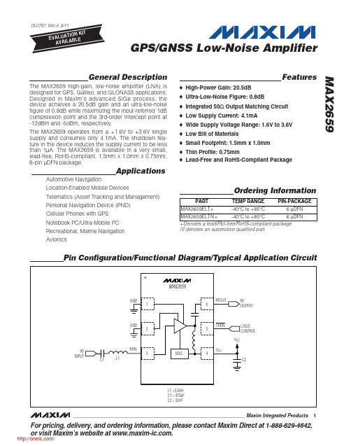
GPS/GNSS Low-Noise Amplifier
General Description
The MAX2659 high-gain, low-noise amplifier (LNA) is designed for GPS, Galileo, and GLONASS applications. Designed in Maxim’s advanced SiGe process, the device achieves a 20.5dB gain and an ultra-low-noise figure of 0.8dB while maximizing the input-referred 1dB compression point and the 3rd-order intercept point at -12dBm and -5dBm, respectively.
Note 4: Measured with a tone located at 5MHz offset from the center of the GPS band.
2 _______________________________________________________________________________________ /
MAX941CSA中文资料

ELECTRICAL CHARACTERISTICS
(V+ = 2.7V to 6.0V, TA = TMIN to TMAX, unless otherwise noted. Typical values are at TA = +25°C. See Note 14.)
PARAMETER Positive Supply Voltage Input Voltage Range
Internal hysteresis ensures clean output switching, even with slow-moving input signals. The MAX941 features latch enable and device shutdown.
The single MAX941 and dual MAX942 are offered in a tiny µMAX package. Both the single and dual MAX942 are available in 8-pin DIP and SO packages. The quad MAX944 comes in 14-pin DIP and narrow SO packages.
__________________________________________________________Pin Configurations
TOP VIEW
MAX941
V+ 1 IN+ 2 IN- 3 SHDN 4
8 N.C. 7 OUT 6 GND 5 LATCH
DIP/SO/µMAX
SYMBOL V+
V
MIN TYP MAX UNITS
MAX2605-MAX2609中文资料
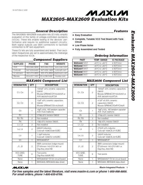
General DescriptionThe MAX2605–MAX2609 evaluation kits (EV kits) simplify evaluation of this family of voltage-controlled oscillators (VCOs). These kits enable testing of the devices’ per-formance and require no additional support circuitry.Both signal outputs use SMA connectors to facilitate connection to RF test equipment.These EV kits are fully assembled and tested. Their oscil-lation frequencies are set to approximately the midrange of the respective VCOs.Featureso Easy Evaluationo Complete, Tunable VCO Test Board with Tank Circuit o Low Phase Noiseo Fully Assembled and TestedEvaluate: MAX2605–MAX2609MAX2605–MAX2609 Evaluation Kits19-1673 Rev 0; 9/00Ordering InformationComponent SuppliersFor free samples and the latest literature, visit or phone 1-800-998-8800.For small orders, phone 1-800-835-8769.MAX2606 Component ListMAX2605 Component ListE v a l u a t e : M A X 2605–M A X 2609MAX2605–MAX2609 Evaluation Kits 2_______________________________________________________________________________________Quick StartThe MAX2605–MAX2609 evaluation kits are fully assembled and factory tested. Follow the instructions in the Connections a nd Setup section for proper device evaluation.Test Equipment Required•Low-noise power supplies (these are recommended for oscillator noise measurement). Noise or ripple will frequency-modulate the oscillator and cause spectral spreading. Batteries can be used in place of power supplies, if necessary.– Use a DC power supply capable of supplying +2.7V to +5.5V. Alternatively, use two or three 1.5V batteries.– Use a DC power supply capable of supplying +0.4V to +2.4V, continuously variable, for TUNE.Alternatively, use two 1.5V batteries with a resistive voltage divider or potentiometer.•An RF spectrum analyzer that covers the operating frequency range of the MAX2605–MAX2609• A 50Ωcoaxial cable with SMA connectors •An ammeter (optional)Connections and Setup1)Connect a DC supply (preset to +3V) to the V CC and GND terminals (through an ammeter, if desired) on the EV kit.2)Turn on the DC supply. If used, the ammeter readingMAX2607 Component ListMAX2608 Component ListEvaluate: MAX2605–MAX2609MAX2605–MAX2609 Evaluation Kits_______________________________________________________________________________________3approximates the typical operating current specified in the MAX2605–MAX2609 data sheet.3)Connect the VCO output (OUT+ or OUT-) to a spec-trum analyzer with a 50Ωcoaxial cable.4)Apply a positive variable DC voltage between 0.4V and 2.4V to TUNE.5)Check the tuning bandwidth on the spectrum analyz-er by varying the tuning voltage (+0.4V to +2.4V).Layout ConsiderationsThe EV kit PC board can serve as a guide for laying out a board using the MAX2605–MAX2609. Generally, the VCC pin on the PC board should have a decoupling capacitor placed close to the IC. This minimizes noisecoupling from the supply. Also, place the VCO as far away as possible from the noisy section of a larger sys-tem, such as a switching regulator or digital circuits.The VCO ’s performance is strongly dependent on the availability of the external tuning inductor. For best per-formance, use high-Q components and choose their val-ues carefully. To minimize the effects of parasitic ele-ments, which degrade circuit performance, place the tuning inductor and C BYP close to the VCO. For higher-frequency versions, include the parasitic PC board inductance and capacitance when calculating the oscillation frequency. In addition, remove the ground plane around and under the tuning inductor to minimize the effect of parasitic capacitance.Noise on TUNE translates into FM noise on the outputs;therefore, keep the trace between TUNE and the control circuitry as short as possible. If necessary, use an RC filter to further suppress noise, as done on the EV kits.E v a l u a t e : M A X 2605–M A X 2609MAX2605–MAX2609 Evaluation Kits 4_______________________________________________________________________________________Figure 2. MAX2608/MAX2609 EV Kits SchematicFigure 1. MAX2605/MAX2606/MAX2607 EV Kits SchematicEvaluate: MAX2605–MAX2609MAX2605–MAX2609 Evaluation Kits_______________________________________________________________________________________5Figure 3. MAX2605/MAX2606/MAX2607 EV Kits ComponentPlacement Guide—Top Silk ScreenFigure 4. MAX2608/MAX2609 EV Kits Component PlacementGuide—Top Silk ScreenFigure 5. MAX2605/MAX2606/MAX2607 EV Kits PC BoardLayout—Component SideFigure 6. MAX2608/MAX2609 EV Kits PC Board Layout—Component SideMa xim ca nnot a ssume responsibility for use of a ny circuitry other tha n circuitry entirely embodied in a Ma xim product. No circuit pa tent licenses a re implied. Maxim reserves the right to change the circuitry and specifications without notice at any time.6_____________________Maxim Integrated Products, 120 San Gabriel Drive, Sunnyvale, CA 94086 408-737-7600©2000 Maxim Integrated ProductsPrinted USAis a registered trademark of Maxim Integrated Products.E v a l u a t e : M A X 2605–M A X 2609MAX2605–MAX2609 Evaluation Kits Figure 7. MAX2605/MAX2606/MAX2607/MAX2608/MAX2609EV Kits PC Board Layout—Ground Plane。
MAX8510 MAX8511 MAX8512 极低噪声、低掉电的线性调压器说明说明书

General DescriptionThe MAX8510/MAX8511/MAX8512 ultra-low-noise, low-dropout (LDO) linear regulators are designed to deliver up to 120mA continuous output current. These regulators achieve a low 120mV dropout for 120mA load current. The MAX8510 uses an advanced architecture to achieve ultra-low output voltage noise of 11μV RMS and PSRR of 54dB at 100kHz.The MAX8511 does not require a bypass capacitor, hence achieving the smallest PC board area. The MAX8512’s output voltage can be adjusted with an external divider.The MAX8510/MAX8511 are preset to a variety of voltag-es in the 1.5V to 4.5V range. Designed with a P-channel MOSFET series pass transistor, the MAX8510/MAX8511/MAX8512 maintain very low ground current (40μA).The regulators are designed and optimized to work with low-value, low-cost ceramic capacitors. The MAX8510 requires only 1μF (typ) of output capacitance for stability with any load. When disabled, current consumption drops to below 1μA.Package options include a 5-pin SC70 and a tiny 2mm x 2mm x 0.8mm TDFN package.Applications●Cellular and Cordless Phones ●PDA and Palmtop Computers ●Base Stations●Bluetooth Portable Radios and Accessories ●Wireless LANs ●Digital Cameras ●Personal Stereos●Portable and Battery-Powered EquipmentFeatures●Space-Saving SC70 and TDFN (2mm x 2mm) Packages ●11μV RMS Output Noise at 100Hz to 100kHzBandwidth (MAX8510)●78dB PSRR at 1kHz (MAX8510) ●120mV Dropout at 120mA Load●Stable with 1μF Ceramic Capacitor for Any Load ●Guaranteed 120mA Output●Only Need Input and Output Capacitors (MAX8511) ●Output Voltages: 1.5V, 1.8V, 2.5V, 2.6V, 2.7V, 2.8V,2.85V, 3V,3.3V,4.5V (MAX8510/MAX8511) and Adjustable (MAX8512) ●Low 40μA Ground Current ●Excellent Load/Line Transient●Overcurrent and Thermal Protection19-2732; Rev 5; 5/19Output Voltage Selector Guide appears at end of data sheet.Ordering Information continued at end of data sheet.*xy is the output voltage code (see Output Voltage Selector Guide). Other versions between 1.5V and 4.5V are available in 100mV increments. Contact factory for other versions.+Denotes a lead(Pb)-free/RoHS-compliant package.T = Tape and reel.PART*TEMP RANGE PIN-PACKAGEMAX8510EXKxy+T -40°C to +85°C 5 SC70MAX8510/MAX8511/MAX8512Ultra-Low-Noise, High PSRR,Low-Dropout, 120mA Linear RegulatorsOrdering InformationClick here for production status of specific part numbers.IN to GND ................................................................-0.3V to +7V Output Short-Circuit Duration ...........................................Infinite OUT, SHDN to GND .....................................-0.3V to (IN + 0.3V)FB, BP , N.C. to GND ................................-0.3V to (OUT + 0.3V)Continuous Power Dissipation (T A = +70°C)5-Pin SC70 (derate 3.1mW/°C above +70°C) .............0.247W 8-Pin TDFN (derate 11.9mW/°C above = 70°C) .........0.953W Operating Temperature Range ...........................-40°C to +85°CMilitary Operating Temperature Range .............-55°C to +110°C Junction Temperature ......................................................+150°C Storage Temperature Range ............................-65°C to +150°C Lead Temperature (soldering, 10s) .................................+300°C Soldering Temperature (reflow) .......................................+260°C Lead (Pb)-free packages .................................................+260°C Packages containing lead (Pb) .......................................+240°C(Note 1)SC70Junction-to-Ambient Thermal Resistance (θJA ) ........324°C/W Junction-to-Case Thermal Resistance (θJC ) .............115°C/WTDFNJunction-to-Ambient Thermal Resistance (θJA ) .......83.9°C/W Junction-to-Case Thermal Resistance (θJC ) ...............37°C/W(V IN = V OUT + 0.5V, T A = -40°C to +85°C, unless otherwise noted. C IN = 1μF, C OUT = 1μF, C BP = 10nF. Typical values are at +25°C; the MAX8512 is tested with 2.45V output, unless otherwise noted.) (Note 2)PARAMETER SYMBOL CONDITIONSMIN TYPMAX UNITS Input Voltage Range V IN26VOutput Voltage Accuracy I OUT = 1mA, T A = +25°C-1+1%I OUT = 100µA to 80mA, T A = +25°C -2+2I OUT = 100µA to 80mA-3+3Maximum Output Current I OUT 120mA Current LimitI LIMV OUT = 90% of nominal value 130200300mA Dropout Voltage (Note 3)V OUT ≥ 3V, I OUT = 80mA 80170mVV OUT ≥ 3V, I OUT = 120mA1202.5V ≤ V OUT < 3V, I OUT = 80mA 902002.5V ≤ V OUT < 3V, I OUT = 120mA 1352V ≤ V OUT < 2.5V, I OUT = 80mA 1202502V ≤ V OUT < 2.5V, I OUT = 120mA180Ground Current I Q I OUT = 0.05mA4090µA V IN = V OUT (nom) - 0.1V, I OUT = 0mA 220500Line Regulation V LNR V IN = (V OUT + 0.5V) to 6V, I OUT = 0.1mA 0.001%/V Load RegulationV LDR I OUT = 1mA to 80mA 0.003%/mA Shutdown Supply CurrentI SHDNV SHDN = 0VT A = +25°C 0.0031µAT A = +85°C 0.05Ripple RejectionPSRRf = 1kHz, I OUT = 10mAMAX851078dBMAX8511/MAX851272f = 10kHz, I OUT = 10mA MAX851075MAX8511/MAX851265f = 100kHz, I OUT = 10mAMAX851054MAX8511/ MAX851246MAX8512Low-Dropout, 120mA Linear RegulatorsAbsolute Maximum RatingsStresses beyond those listed under “Absolute Maximum Ratings” may cause permanent damage to the device. These are stress ratings only, and functional operation of the device at these or any other conditions beyond those indicated in the operational sections of the specifications is not implied. Exposure to absolute maximum rating conditions for extended periods may affect device reliability.Electrical CharacteristicsPackage Thermal Characteristics Note 1: Package thermal resistances were obtained using the method described in JEDEC specification JESD51-7, using a four-layerboard. For detailed information on package thermal considerations, refer to /thermal-tutorial .(V IN = V OUT + 0.5V, T A = -40°C to +85°C, unless otherwise noted. C IN = 1μF, C OUT = 1μF, C BP = 10nF. Typical values are at +25°C; the MAX8512 is tested with 2.45V output, unless otherwise noted.) (Note 2)Note 2: Limits are 100% tested at +25°C. Limits over operating temperature range are guaranteed by design.Note 3: Dropout is defined as V IN - V OUT when V OUT is 100mV below the value of V OUT for V IN = V OUT + 0.5V.Note 4: Time needed for V OUT to reach 90% of final value.(V IN = V OUT + 0.5V, C IN = 1μF, C OUT = 1μF, C BP = 10nF, T A = +25°C, unless otherwise noted.)PARAMETER SYMBOLCONDITIONSMINTYP MAXUNITSOutput Noise Voltage (RMS)f = 100Hz to 100kHz, I LOAD = 10mA MAX851011µVMAX8511/MAX8512230f = 100Hz to 100kHz, I LOAD = 80mA MAX851013MAX8511/MAX8512230Shutdown Exit Delay R LOAD = 50Ω (Note 4)300µs SHDN Logic Low Level V IN = 2V to 6V 0.4V SHDN Logic High Level V IN = 2V to 6V 1.5V SHDN Input Bias Current V IN = 6V, V SHDN = 0V or 6VT A = +25°C µA T A = +85°C 0.01FB Input Bias Current (MAX8512)V IN = 6V,V FB = 1.3VT A = +25°C 0.0060.1µA T A = +85°C0.01Thermal Shutdown 160°C Thermal-Shutdown Hysteresis10°C MAX8510OUTPUT VOLTAGE ACCURACYvs. LOAD CURRENTM A X 8510 t o c 02LOAD CURRENT (mA)% D E V I A T I O N (%)10080604020-0.4-0.200.20.40.6-0.60120MAX8510OUTPUT VOLTAGE ACCURACYvs. TEMPERATURETEMPERATURE (°C)% D E V I A T I O N (%)603510-15-0.8-0.6-0.4-0.200.20.40.60.81.0-1.0-4085MAX8510OUTPUT VOLTAGE vs. INPUT VOLTAGEINPUT VOLTAGE (V)O U T P U T V O L T A G E (V )543210.51.01.52.02.53.00.06MAX8512Low-Dropout, 120mA Linear RegulatorsElectrical Characteristics (continued)Typical Operating Characteristics(V IN = V OUT + 0.5V, C IN = 1μF, C OUT = 1μF, C BP = 10nF, T A = +25°C, unless otherwise noted.)MAX8510DROPOUT VOLTAGE vs. OUTPUT VOLTAGEOUTPUT (V)D R O P O U T V O L T A G E (m V )3.02.82.62.42.2501001502002502.03.2MAX8510GROUND PIN CURRENT vs. TEMPERATUREM A X 8510 t o c 08TEMPERATURE (°C)G R O U N D P I N C U R R E N T (µA )603510-153540455030-4085MAX8510OUTPUT NOISE400µs/divMAX8510GROUND PIN CURRENT vs. INPUT VOLTAGEINPUT VOLTAGE (V)G R O U N D P I N C U R R E N T (µA )43211502005010025030035005MAX8510PSRR vs. FREQUENCYFREQUENCY (kHz)P S R R (d B )1101000.14050601020307080900.011000MAX8510OUTPUT NOISE SPECTRAL DENSITYvs. FREQUENCYMAX8510 toc12FREQUENCY (kHz)O U T P U T N O I S E D E N S I T Y (n V /H z )0.11101001.E+031.E+021.E+041.E+010.011000MAX8510DROPOUT VOLTAGE vs. LOAD CURRENTLOAD CURRENT (mA)D R O P O U T V O L T A G E (m V )1008060402030609012015000120MAX8510GROUND PIN CURRENT vs. LOAD CURRENTLOAD CURRENT (mA)G R O U N D P I N C U R R E N T (µA )10080604020408012016020024000120MAX8511PSRR vs. FREQUENCYFREQUENCY (kHz)P S R R (d B )0.111010040506010203070809000.011000MAX8512Low-Dropout, 120mA Linear RegulatorsTypical Operating Characteristics (continued)(V IN = V OUT + 0.5V, C IN = 1μF, C OUT = 1μF, C BP = 10nF, T A= +25°C, unless otherwise noted.)MAX8510LOAD TRANSIENT RESPONSE1ms/div V OUT 10mV/divMAX8510EXITING SHUTDOWN WAVEFORM20µs/divV OUT = 2.85VR LOAD = 47ΩOUTPUT VOLTAGE 2V/divSHUTDOWN VOLTAGEMAX8510LOAD TRANSIENT RESPONSE NEAR DROPOUT1ms/divV OUT 10mV/divMAX8510ENTERING SHUTDOWN DELAY40µs/divC BP = 0.01µFOUTPUT VOLTAGE 2V/divSHUTDOWN VOLTAGEMAX8510REGION OF STABLE C OUT ESRvs. LOAD CURRENTM A X 8510 t o c 20LOAD CURRENT (mA)C O U T E S R (Ω)806040200.11101000.01120100STABLE REGIONMAX8510OUTPUT NOISE vs. BP CAPACITANCEM A X 8510 t o c 13BP CAPACITANCE (nF)O U T P U T N O I S E (µV )1051015202501100MAX8510LINE TRANSIENT RESPONSE200µs/divV IN = 3.5V TO 4VV OUT 2mV/divMAX8510SHUTDOWN EXIT DELAY20µs/divV OUT 1V/divSHUTDOWN VOLTAGEV OUT = 3V C BP = 100nFMAX8512Low-Dropout, 120mA Linear RegulatorsTypical Operating Characteristics (continued)Detailed DescriptionThe MAX8510/MAX8511/MAX8512 are ultra-low-noise, low-dropout, low-quiescent current linear regulators designed for space-restricted applications. The parts are available with preset output voltages ranging from 1.5V to 4.5V in 100mV increments. These devices can supply loads up to 120mA. As shown in the Functional Diagram , the MAX8510/MAX8511 consist of an innovative bandgap core and noise bypass circuit, error amplifier, P-channel pass transistor, and internal feedback voltage-divider. The MAX8512 allows for adjustable output with an external feedback network.The 1.225V bandgap reference is connected to the error amplifier’s inverting input. The error amplifier compares this reference with the feedback voltage and amplifies the difference. If the feedback voltage is lower than the refer-ence voltage, the pass-transistor gate is pulled low. This allows more current to pass to the output and increases the output voltage. If the feedback voltage is too high, the pass transistor gate is pulled high, allowing less cur-rent to pass to the output. The output voltage is fed back through an internal resistor voltage-divider connected to the OUT pin.An external bypass capacitor connected to BP (MAX8510) reduces noise at the output. Additional blocks include a current limiter, thermal sensor, and shutdown logic.Internal P-Channel Pass TransistorThe MAX8510/MAX8511/MAX8512 feature a 1Ω (typ) P-channel MOSFET pass transistor. This provides sev-eral advantages over similar designs using a PNP pass transistor, including longer battery life. The P-channel MOSFET requires no base drive, which considerably reduces quiescent current. PNP-based regulators waste considerable current in dropout when the pass transistor saturates. They also use high base-drive current under heavy loads. The MAX8510/MAX8511/MAX8512 do not suffer from these problems and consume only 40μA of quiescent current in light load and 220μA in dropout (see the Typical Operating Characteristics ).Output Voltage SelectionThe MAX8510/MAX8511 are supplied with factory-set output voltages from 1.5V to 4.5V, in 100mV increments (see Ordering Information ). The MAX8512 features a user-adjustable output through an external feedback net-work (see the Typical Operating Circuits ).To set the output of the MAX8512, use the following equa-tion:OUT REF V R1R2X -1V=where R2 is chosen to be less than 240kΩ and V REF = 1.225V. Use 1% or better resistors.PINNAMEFUNCTIONMAX8510MAX8511MAX8512SC70TDFN -EP SC70TDFN -EP SC70TDFN -EP 151515IN Unregulated Input Supply 232323GNDGround343434SHDN Shutdown. Pull low to disable the regulator.42————BP Noise Bypass for Low-Noise Operation. Connect a 10nF capacitor from BP to OUT. BP is shorted to OUT in shutdown mode.————42FB Adjustable Output Feedback Point575757OUT Regulated Output Voltage. Bypass with a capacitor to GND. See the Capacitor Selection and Regulator Stability section for more details.—1, 6, 841, 2, 6,—1, 6, 8N.C.No connection. Not internally connected.——————EPExposed Pad (TDFN Only). Internally connected to GND. Connect to a large ground plane to maximize thermal performance. Not intended as an electrical connection point.MAX8512Low-Dropout, 120mA Linear RegulatorsPin DescriptionShutdownThe MAX8510/MAX8511/MAX8512 feature a low-power shutdown mode that reduces quiescent current less than 1μA. Driving SHDN low disables the voltage reference, error amplifier, gate-drive circuitry, and pass transistor (see the Functional Diagram), and the device output enters a high-impedance state. Connect SHDN to IN for normal operation.Current LimitThe MAX8510/MAX8511/MAX8512 include a current lim-iter, which monitors and controls the pass transistor’s gate voltage, limiting the output current to 200mA. For design purposes, consider the current limit to be 130mA (min) to 300mA (max). The output can be shorted to ground for an indefinite amount of time without damaging the part. Thermal-Overload ProtectionThermal-overload protection limits total power dissipation in the MAX8510/MAX8511/MAX8512. When the junction temperature exceeds T J = +160°C, the thermal sensor signals the shutdown logic, turning off the pass transis-tor and allowing the IC to cool down. The thermal sensor turns the pass transistor on again after the IC’s junction temperature drops by 10°C, resulting in a pulsed output during continuous thermal-overload conditions.Thermal-overload protection is designed to protect the MAX8510/MAX8511/MAX8512 in the event of a fault con-dition. For continual operation, do not exceed the abso-lute maximum junction temperature rating of T J = +150°C. Operating Region and Power DissipationThe MAX8510/MAX8511/MAX8512 maximum power dis-sipation depends on the thermal resistance of the case and circuit board, the temperature difference between the die junction and ambient, and the rate of airflow. The power dissipation across the device is:P = I OUT (V IN - V OUT)The maximum power dissipation is:P MAX = (T J - T A) / (θJC + θCA)where T J - T A is the temperature difference between the MAX8510/MAX8511/MAX8512 die junction and the sur-rounding air, θJC is the thermal resistance of the package, and θCA is the thermal resistance through the PC board, copper traces, and other materials to the surrounding air. The GND pin of the MAX8510/MAX8511/MAX8512 per-forms the dual function of providing an electrical connec-tion to ground and channeling heat away. Connect the GND pin to ground using a large pad or ground plane.Noise ReductionFor the MAX8510, an external 0.01μF bypass capaci-tor between BP and OUT with innovative noise bypass scheme reduces output noises dramatically, exhibiting 11μV RMS of output voltage noise with C BP = 0.01μF and C OUT = 1μF. Startup time is minimized by a poweron cir-cuit that precharges the bypass capacitor. Applications InformationCapacitor Selectionand Regulator StabilityUse a 1μF capacitor on the MAX8510/MAX8511/MAX8512 input and a 1μF capacitor on the output. Larger input capacitor values and lower ESRs provide better noise rejection and line-transient response. Reduce output noise and improve load-transient response, stability, and power-supply rejection by using large output capacitors. Note that some ceramic dielectrics exhibit large capaci-tance and ESR variation with temperature. With dielec-trics such as Z5U and Y5V, it may be necessary to use a 2.2μF or larger output capacitor to ensure stability at temperatures below -10°C. With X7R or X5R dielectrics, 1μF is sufficient at all operating temperatures. A graph of the region of stable C OUT ESR vs. load current is shown in the Typical Operating Characteristics.Use a 0.01μF bypass capacitor at BP (MAX8510) for low-output voltage noise. The leakage current going into the BP pin should be less than 10nA. Increasing the capaci-tance slightly decreases the output noise. Values above 0.1μF and below 0.001μF are not recommended. Noise, PSRR, and Transient ResponseThe MAX8510/MAX8511/MAX8512 are designed to deliv-er ultra-low noise and high PSRR, as well as low dropout and low quiescent currents in battery-powered systems. The MAX8510 power-supply rejection is 78dB at 1kHz and 54dB at 100kHz. The MAX8511/MAX8512 PSRR is 72dB at 1kHz and 46dB at 100kHz (see the Power-Supply Rejection Ratio vs. Frequency graph in the Typical Operating Characteristics).When operating from sources other than batteries, improved supply-noise rejection and transient response can be achieved by increasing the values of the input and output bypass capacitors, and through passive filter-ing techniques. The Typical Operating Characteristics show the MAX8510/MAX8511/MAX8512 line- and load-transient responses.MAX8512Low-Dropout, 120mA Linear RegulatorsDropout VoltageA regulator’s minimum dropout voltage determines the lowest usable supply voltage. In battery-powered sys-tems, this determines the useful end-of-life battery volt-age. Because the MAX8510/MAX8511/MAX8512 use aP-channel MOSFET pass transistor, their dropout voltage is a function of drain-to-source on-resistance (RDS(ON)) multiplied by the load current (see the Typical Operating Characteristics ).MAX8512Low-Dropout, 120mA Linear RegulatorsFunctional Diagram*xy is the output voltage code (see Output Voltage Selector Guide). Other versions between 1.5V and 4.5V are available in 100mV increments. Contact factory for other versions.**EP = Exposed pad.+Denotes a lead(Pb)-free/RoHS-compliant package.T = Tape and reel.(Note: Standard output voltage options, shown in bold , are available. Contact the factory for other output voltages between 1.5V and 4.5V. Minimum order quantity is 15,000 units.)PART*TEMP RANGE PIN-PACKAGE MAX8510MXK33/PR3+-55°C to +110°C 5 SC70MAX8510ETAxy+T -40°C to +85°C 8 TDFN-EP** 2mm x 2mm MAX8511EXKxy+T -40°C to +85°C 5 SC70MAX8511ETAxy+T -40°C to +85°C 8 TDFN-EP** 2mm x 2mm MAX8512EXK+T -40°C to +85°C 5 SC70MAX8512ETA+T-40°C to +85°C8 TDFN-EP** 2mm x 2mmPARTV OUT (V)TOP MARKMAX8510EXK16+T 1.6AEX MAX8510EXK18+T 1.8AEA MAX8510ETA25+T 2.5AAO MAX8510EXK27+T 2.7ATD MAX8510ETA28+T 2.8AAR MAX8510EXK29+T 2.85ADS MAX8510MXK33/PR3+ 3.3AUV MAX8510ETA30+T 3AAS MAX8510ETA33+T 3.3AAT MAX8510ETA45+T 4.5AAU MAX8510MXK33/PR3+ 3.3AUV MAX8511EXK15+T 1.5ADU MAX8511ETA18+T 1.8AAV MAX8511ETA25+T 2.5AAP MAX8511ETA26+T 2.6AAW MAX8511EXK28+T 2.8AFA MAX8511ETA29+T 2.85AAX MAX8511EXK89+T 2.9AEH MAX8511EXK31+T 3.1ARS MAX8511ETA33+T 3.3AAY MAX8511EXK45+T4.5AEJ MAX8512ETA+TAdjustableAAQPACKAGE TYPE PACKAGE CODE OUTLINE ND PATTERN NO.8 TDFN T822+121-016890-00645 SC70X5+121-007690-0188MAX8512Low-Dropout, 120mA Linear RegulatorsTypical Operating Circuits (continued)Ordering Information (continued)Output Voltage Selector GuidePackage InformationFor the latest package outline information and land patterns (footprints), go to /packages . Note that a “+”, “#”, or “-” in the package code indicates RoHS status only. Package drawings may show a different suffix character, but the drawing pertains to the package regardless of RoHS status.Chip InformationPROCESS: BiCMOSREVISION NUMBERREVISION DATE DESCRIPTIONPAGES CHANGED 48/11Corrected errors and added lead-free packages 1, 2, 3, 6, 955/19Updated Output Voltage Selector Guide9Maxim Integrated cannot assume responsibility for use of any circuitry other than circuitry entirely embodied in a Maxim Integrated product. No circuit patent licenses are implied. Maxim Integrated reserves the right to change the circuitry and specifications without notice at any time. The parametric values (min and max limits) shown in the Electrical Characteristics table are guaranteed. Other parametric values quoted in this data sheet are provided for guidance.MAX8512Low-Dropout, 120mA Linear RegulatorsRevision HistoryFor pricing, delivery, and ordering information, please visit Maxim Integrated’s online storefront at https:///en/storefront/storefront.html.。
ADDA转换器元件集.
ADDA转换器元件集第一部分A/D、D/A转换器基本知识第1章A/D转换器基本原理1.1 A/D转换器概述1.1.1 A/D转换器的作用1.1.2 A/D转换器的编码1.2 A/D转换器的常用术语及性能指标1.3 A/D转换器误差及其对系统性能的影响1.3.1 数据采集系统的误差分配1.3.2 A/D转换器自身的误差1.3.3 数据采集系统的噪声第2章A/D转换器的种类及结构2.1 逐次逼近型A/D转换器2.2 流水线型A/D转换器-型A/D转换器2.4 闪速A/D转换器2.5 积分型A/D转换器2.6 压频转换器2.7 智能A/D转换器2.7.1 智能A/D转换器还是带A/D转换器的控制器2.7.2 作为智能A/D转换器的MSC1210第3章A/D转换器外围电路3.1 信号调理电路3.1.1 电桥3.1.2 信号放大或衰减3.1.3 信号隔离3.1.4 滤波3.2 电压基准的特性及选用3.2.1 电压基准的主要参数3.2.2 常用电压基准的类型3.2.3 电压基准的选用第4章D/A转换器基本原理及分类4.1 D/A转换器基本概念及常用术语4.1.1 D/A转换器的用途4.1.2 D/A转换器的常用术语4.2 D/A转换器的误差及失真4.3 D/A转换器的种类及结构4.3.1 D/A转换器结构简介4.3.2 Kelvin分压器(Kelvin Divider)4.3.3 全解码型D/A转换器4.3.4 二进制加权型D/A转换器(Binary-Weighted DAC)4.3.5 倒T形D/A转换器4.3.6 分段型D/A转换器4.3.7 过采样/内插D/A转换器第二部分A/D、D/A转换器手册A/D转换器选型表D/A转换器选型表A/D、D/A转换器手册ICL7126MAX138/MAX139/MAX140MAX1492/MAX1494TC14433/TC14433AICL7135ICL7135C/TLC7135CTC7135AD570/AD571AD7466/AD7467/AD7468AD7476/AD7477/AD7478AD7476A/AD7477A/AD7478AADCS7476/ADCS7477/ADCS7478AD7813ADC0801/ADC0802/ADC0803/ADC0804/ADC0805 ADC0820TLC0820AC/TLC0820AIAD7820ADC08031/ADC08032/ADC08034/ADC08038 ADC08060ADC08L060ADC08100ADC08200ADC1173ADC1175ADC1175-5ADC08061/ADC08062ADC08161ADC08131/ADC08134/ADC08138ADC08351ADC08831/ADC08832ADCV0831ADS830/ADS831ADS930/ADS931ADS7826/ADS7827/ADS7829MAX100MAX101AMAX104MAX106MAX108MAX152MAX165/MAX166TLC5510/TLC5510A/TLC5540TLC548/TLC549AD876AD578/AD579AD7451/AD7441AD7470/AD7472AD7910/AD7920AD9060AD7810ADC1005ADC1001ADC1061ADC10030ADC10040ADC10065ADC10080ADC10061/ADC10062/ADC10064ADC10461/ADC10462/ADC10464ADC10321ADC10221ADC10731/ADC10732/ADC10734/ADC10738 ADS820/ADS821ADS822/ADS823/ADS825/ADS826/ADS828 ADS5102/ADS5103LTC1091/LTC1092/LTC1093/LTC1094LTC1197/LTC1197L/LTC1199/LTC1199L LTC1392TLV1572MAX151MAX1444MAX1446MAX1448MAX1449MAX1426MAX1425MCP3001THS1030/THS1031THS1040/THS1041TLC1549C/TLC1549I/TLC1549MTLV1549C/TLC1549I/TLC1549MAD572AD574AAD674BAD774BAD678AD871AD1671AD1672AD7450/AD7450A/AD7440AD7452/AD7453AD7457AD7475/AD7495AD7482AD7490AD7492/AD7492-5AD7572AD7572AAD7853/AD7853LAD7854/AD7854LAD7870/AD7875/AD7876AD7870AAD7878AD7893AD7895AD7896AD7898AD9221/AD9223/AD9220ADC912AADC12L066ADC12L063ADC1241ADC1251ADC12010ADC12020ADC12040ADC12H030/ADC12H032/ADC12H034/ADC12H038 ADC12030/ADC12032/ADC12034/ADC12038ADC12041ADC12081ADC12181/ADC12191ADC12281ADC12441ADC12451ADS807ADS1286ADS5410ADS800/ADS801/ADS802 ADS803/ADS804/ADS805 ADS808/ADS809ADS1286ADS5220/ADS5221ADS5410ADS7804ADS7806ADS7808ADS7810ADS7812ADS7816ADS7817ADS7818ADS7822ADS7823ADS7834ADS7835ADS7881CLC5957ICL7109TC7109/TC7109ALTC1272LTC1273/LTC75/LTC76 LTC1274/LTC1277LTC1278LTC1279LTC1282LTC1285/LTC1288LTC1286/LTC1298ADS1286LTC1287LTC1292/LTC1297LTC1400LTC1401LTC1402LTC1404LTC1405LTC1409LTC1410LTC1412LTC1415LTC1420LTC1860/LTC1861LTC1860L/LTC1861LMAX162/MX7572MAX170MAX1211MCP3201TC7109/TC7109ATHS1215/THS1230ADC14061ADC14071ADC14161MAX194MAX1156/MAX1158/MAX1174 MAX1157/MAX1159/MAX1175 ADS850AD679AD7484AD7485AD7871/AD7872AD7894AD7940AD9241AD9243AD7851TLC3541/TLC3545ADS850ADS5421ADS8324THS1401/THS1403/THS1408 THS14F01/THS14F03THS1401-EP/03-EP/08-EPAD676AD1376/AD1377AD9260AD7701AD7715AD7720AD7722AD7723AD7725ADC16061ADS1202ADS7805TLC4541/TLC4545ADS1100/ADS1110ADS1605/ADS1606ADS7807ADS7809ADS7811/ADS7815ADS7813ADS8320/ADS8321ADS8322/ADS8323ADS8325ADS8371ADS8401/ADS8402ADS8411/ADS8412LTC1603LTC1608LTC1864/LTC1865LTC2433-1MAX195MAX1162MAX1165/MAX1166MAX1169MAX1178/MAX1188MAX1179/1187/1189MAX1460MAX1462TC3400TC500/TC500A/TC510/TC514 AD7703LTC2421/LTC2422AD1555/AD1556LTC2401/LTC2402MAX105MAX107MAX1197MAX1198THS0842ADC10D020ADC10D040ADS5203/ADS5204AD7866ADC10D040MAX133/MAX134AD7904/AD7914/AD7924 AD7908/AD7918/AD7928ADC0808/ADC0809ADC0816/ADC0817ADC0844/ADC0848MAX1191MAX1193MAX1195MAX1196TLC0834/TLC0838LTC0831/LTC0832TLC540/TLC541/TLC542AD7911/AD7921AD7912/AD7922AD7934/AD7933AD7936/AD7935AD7938/AD7939AD7994/AD7993AD7998/AD7997AD7776/AD7777/AD7778AD7811/AD7812AD7816/AD7817/AD7818ADC10154/ADC10158ADC10662/ADC10664ADS5120/ADS5121/ADS5122 LTC1090LTC1283LTC1852/LTC1853MAX1090/MAX1092MAX1091/MAX1093MCP3002MCP3004/MCP3008THS1007/THS1009THS10064/THS10082TLC1550I/TLC1550M/TLC1551I TLC1541/TLC1542/TLC1543 TLC1514/TLC1518TLV1571/TLV1578TLV1570TLV1562TLV1543C/TLV1543I/TLV1543M TLV1504/TLV1508AD7858/AD7858LAD7859/AD7859LAD7862AD7864AD7873AD7874AD7880AD7886AD7887AD7888AD7890AD7891AD7892AD7923AD7927AD7992ADC12L030/ADC12L032/ADC12L034/ADC12L038 ADC78H89ADC12048ADC12062ADC12130/ADC12132/ADC12138ADC12662ADS2806/ADS2807ADS7800ADS7824ADS7828ADS7841ADS7842ADS7844ADS7852ADS7861ADS7862ADS7864ADS7870LM12L458LM12454/LM12458/LM12H458LTC1289LTC1290LTC1291LTC1293/LTC1294/LTC1296LTC1594L/LTC1598LMAX115/MAX116MAX186/MAX188MAX197MAX1226/MAX1228/MAX1230MAX1290/MAX1292MAX1291/MAX1293MAX1294/MAX1296MAX1295/MAX1297MAX1304~MAX1306/MAX1308~MAX1310/MAX1312~MAX1314 MCP3202MCP3204/MCP3208THS12082THS1206THS1207/THS1209TLV2553/TLV2556TLV2544/TLV2548TLC2543C/TLC2543I/TLC2543MTLV2541/TLV2542/TLV2545TLC3574/TLC3578/TLC2574/TLC2578TLC2554/TLC2558TLC2551/TLC2552/TLC2555AD7856AD7863AD7865AD7899AD7729ADS7871MAX110/MAX111MAX125/MAX126MAX1067/MAX1068TLC3544/TLC3548AD7654AD73360AD7705/AD7706AD7707AD7709AD7721AD7724ADS1112ADS7825ADS8341/ADS8343ADS8342ADS8344/ADS8345ADS8361ADS8364LTC2436-1MAX1167/MAX1168TC3401TC3402TC3403TC3404TC3405TC530/TC534MAX1400MAX1401MAX1402MAX1403LTC2424/LTC2428LTC2404/LTC2408LTC2412LTC2414/LTC2418LTC1426DAC0800/DAC0802DAC0808DAC0830/DAC0832LTC1329-10/LTC1329-50/LTC1329A-50 LTC1428-50MAX5186/MAX5189AD8600DS1851LTC1665/LTC1660LTC1427-50MAX5180/MAX5183MAX5858LTC1661LTC1662LTC1663LTC1664LTC1669MAX5354/MAX5355MAX5158/MAX5159LTC8043LTC7541ALTC7543/LTC8143LTC1590LTC1666/LTC1667/LTC1668LTC1257MAX5886LTC1456LTC1450/LTC1450LLTC1451/LTC1452/LTC1453LTC1659MAX5120/MAX5121MAX5122/MAX5123MAX5174/MAX5176MAX5175/MAX5177MAX5352/MAX5353MX7845AD7237A/AD7247ALTC1446/LTC1446LLTC1448LTC1454/LTC1454LLTC2602/LTC2612/LTC2622 MAX5154/MAX5155MAX5156/MAX5157MX7837/MX7847LTC1458/LTC1458LLTC2600/LTC2610/LTC2620 MAX535/MAX5351MAX5130/MAX5131MAX5132/MAX5133MAX5150/MAX5151MAX5152/MAX5153MAX5839MX7839DAC14135LTC1591/LTC1597MAX5887LTC1654LTC1658MAX5170/MAX5172MAX5171/MAX5173MAX5195MX7841LTC1595/LTC1596/LTC1596-1 LTC1599MAX5888LTC1650LTC1655/LTC1655LLTC1657/LTC1657LLTC1821MAX5200/MAX5203MAX5204/MAX5207MAX5621/MAX5622/MAX5623 MAX5631/MAX5632/MAX5633。
- 1、下载文档前请自行甄别文档内容的完整性,平台不提供额外的编辑、内容补充、找答案等附加服务。
- 2、"仅部分预览"的文档,不可在线预览部分如存在完整性等问题,可反馈申请退款(可完整预览的文档不适用该条件!)。
- 3、如文档侵犯您的权益,请联系客服反馈,我们会尽快为您处理(人工客服工作时间:9:00-18:30)。
37
1 2 3 4 5 6 7 8 9 10 11 12 13 14 15 16 17 18 19 20 21 22 23 24
36 35 34 33 32 31
N.C. N.C. OGND OVDD OVDD OGND N.C. N.C. D0B D1B D2B D3B
Applications
Baseband I/Q Sampling Multichannel IF Sampling Ultrasound and Medical Imaging Battery-Powered Instrumentation WLAN, WWAN, WLL, MMDS Modems Set-Top Boxes VSAT Terminals
Dual, 8-Bit, 60Msps, 3V, Low-Power ADC with Internal Reference and Parallel Outputs MAX1197
ABSOLUTE MAXIMUM RATINGS
VDD, OVDD to GND ...............................................-0.3V to +3.6V OGND to GND.......................................................-0.3V to +0.3V INA+, INA-, INB+, INB- to GND ...............................-0.3V to VDD REFIN, REFOUT, REFP, REFN, COM, CLK to GND .................................-0.3V to (VDD + 0.3V) OE, PD, SLEEP, T/B, D7A–D0A, D7B–D0B to OGND .............................-0.3V to (OVDD + 0.3V) Continuous Power Dissipation (TA = +70°C) 48-Pin TQFP (derate 12.5mW/°C above +70°C).........1000mW Operating Temperature Range ...........................-40°C to +85°C Junction Temperature ......................................................+150°C Storage Temperature Range .............................-60°C to +150°C Lead Temperature (soldering, 10s) .................................+300°C
Features
MAX1197
Ordering Information
PART MAX1197ECM TEMP RANGE -40°C to +85°C PIN-PACKAGE 48 TQFP-EP*
*EP = Exposed paddle Functional Diagram and Pin Compatible Upgrades table appear at end of data sheet.
TQቤተ መጻሕፍቲ ባይዱP-EP
1
For pricing, delivery, and ordering information, please contact Maxim/Dallas Direct! at 1-888-629-4642, or visit Maxim’s website at .
19-2411; Rev 0; 4/02
Dual, 8-Bit, 60Msps, 3V, Low-Power ADC with Internal Reference and Parallel Outputs
General Description
The MAX1197 is a 3V, dual, 8-bit analog-to-digital converter (ADC) featuring fully differential wideband trackand-hold (T/H) inputs, driving two ADCs. The MAX1197 is optimized for low-power, small size, and high-dynamic performance for applications in imaging, instrumentation and digital communications. This ADC operates from a single 2.7V to 3.6V supply, consuming only 120mW while delivering a typical signal-to-noise and distortion (SINAD) of 48.5dB at an input frequency of 30MHz and a sampling rate of 60Msps. The T/H-driven input stages incorporate 400MHz (-3dB) input amplifiers. The converters may also be operated with singleended inputs. In addition to low operating power, the MAX1197 features a 3mA sleep mode as well as a 0.1µA power-down mode to conserve power during idle periods. An internal 2.048V precision bandgap reference sets the full-scale range of the ADC. A flexible reference structure allows the use of this internal or an externally applied reference, if desired, for applications requiring increased accuracy or a different input voltage range. The MAX1197 features parallel, CMOS-compatible threestate outputs. The digital output format can be set to two’s complement or straight offset binary through a single control pin. The device provides for a separate output power supply of 1.7V to 3.6V for flexible interfacing with various logic families. The MAX1197 is available in a 7mm x 7mm, 48-pin TQFP package, and is specified for the extended industrial (-40°C to +85°C) temperature range. Pin-compatible lower and higher speed versions of the MAX1197 are also available. Refer to the MAX1195 data sheet for 40Msps and the MAX1198 data sheet for 100Msps. In addition to these speed grades, this family will include a multiplexed output version (MAX1196, 40Msps), for which digital data is presented time interleaved and on a single, parallel 8-bit output port. For a 10-bit, pin-compatible upgrade, refer to the MAX1182 data sheet. With the N.C. pins of the MAX1197 internally pulled down to ground, this ADC becomes a drop-in replacement for the MAX1182. o Single 2.7V to 3.6V Operation o Excellent Dynamic Performance 48.5dB/45.3dB SINAD at fIN = 30MHz/200MHz 69dBc/53.5dBc SFDR at fIN = 30MHz/200MHz o -72dB Interchannel Crosstalk at fIN = 20MHz o Low Power 120mW (Normal Operation) 9mW (Sleep Mode) 0.3µW (Shutdown Mode) o 0.05dB Gain and ±0.05° Phase Matching o Wide ±1VP-P Differential Analog Input Voltage Range o 400MHz -3dB Input Bandwidth o On-Chip 2.048V Precision Bandgap Reference o User-Selectable Output Format—Two’s Complement or Offset Binary o Pin-Compatible 8-Bit and 10-Bit Upgrades Available