Siemens Pcs7 IO Redundancy Practice in Haihua Aniline Project
PCS_7移植指导

SIMATICPCS 7 V4.x to PCS 7 V5.0 Migration Guide03/2000A5E00064939Edition 01Copyright © Siemens AG 2000 All rights reservedThe reproduction, transmission or use of this document or itscontents is not permitted without express written authority.Offenders will be liable for damages. All rights, including rightscreated by patent grant or registration of a utility model or design,are reserved.Siemens AGBereich Automatisierungs- und AntriebstechnikGeschaeftsgebiet Industrie-AutomatisierungssystemePostfach 4848, D- 90327 Nuernberg Disclaimer of Liability We have checked the contents of this manual for agreement with the hardware and software described. Since deviations cannot be precluded entirely, we cannot guarantee full agreement. However,the data in this manual are reviewed regularly and any necessary corrections included in subsequent editions. Suggestions forimprovement are welcomed.©Siemens AG 2000Technical data subject to change.Siemens Aktiengesellschaft A5E00064939Safety GuidelinesThis manual contains notices which you should observe to ensure your own personal safety, as well as toprotect the product and connected equipment. These notices are highlighted in the manual by a warningtriangle and are marked as follows according to the level of danger:Danger indicates that death, severe personal injury or substantial property damage will result if properprecautions are not taken.Warning indicates that death, severe personal injury or substantial property damage can result if properprecautions are not taken.Caution indicates that minor personal injury or property damage can result if proper precautions are not taken.draws your attention to particularly important information on the product, handling the product, or to a particular part of the documentation.Qualified PersonnelOnly qualified personnel should be allowed to install and work on this equipment. Qualified persons aredefined as persons who are authorized to commission, to ground, and to tag circuits, equipment, andsystems in accordance with established safety practices and standards.Correct UsageNote the following:WarningThis device and its components may only be used for the applications described in the catalog or thetechnical descriptions, and only in connection with devices or components from other manufacturerswhich have been approved or recommended by Siemens.This product can only function correctly and safely if it is transported, stored, set up, and installed correctly, and operated and maintained as recommended.TrademarksSIMATIC®, SIMATIC HMI® and SIMATIC NET® are registered trademarks of SIEMENS AG.Some of other designations used in these documents are also registered trademarks; the owner’s rights maybe violated if they are used by third parties for their own purposes.Migration from PCS7 V4.x to PCS7 V5.0A5E00064939-01iiiContents1Remarks concerning migration.................................................................................1-11.1Extent of migration........................................................................................1-11.2Backup before migration................................................................................1-22Migration without using the new functions..............................................................2-13Complete migration using new functions.................................................................3-13.1Hardware update...........................................................................................3-13.1.1Updating the operating system on the S7-CPU(s) 416-2DP...........................3-13.1.2Updating your IM153-1 and IM153-2 (ET200M).............................................3-23.1.3Handling GSE files........................................................................................3-33.2PCS 7 libraries..............................................................................................3-43.2.1Backup when reusing V4.02 PCS7 libraries...................................................3-43.3Converting the PLC.......................................................................................3-53.3.1SIMATIC Manager: Converting the Plant Hierarchy.......................................3-53.3.2HW Config: Adjust hardware .........................................................................3-53.3.3SIMATIC Manager: Integrate and adapt the blocks from the new libraries....................................................................................3-63.3.4CFC: Integrating and adapting blocks from new libraries................................3-73.3.5CFC: Migration to value labels.......................................................................3-93.3.6CFC: Migration from text attributes to block I/Os..........................................3-103.3.7CFC: Run sequence after changing block types..........................................3-103.3.8SIMATIC Manager: Migrating from CFC library blocks to basic operations (optional)..........................................................................3-113.3.9Converting a project to the new driver blocks (optional)...............................3-133.3.10Updating the sampling interval (option)........................................................3-16ContentsMigration from PCS7 V4.x to PCS7 V5.0iv A5E00064939-013.3.11SFC: Non-latching behavior........................................................................3-163.3.12SFC: SFCs in runtime groups......................................................................3-173.3.13SIMATIC Manager TH: Checking PLC-OS assignment................................3-173.3.14CFC or SFC: Compile and load...................................................................3-183.3.15SIMATIC Manager TH: Checking OS area identifier before transferring data to the OS..........................................................................3-183.4Import-Export Wizard (IEW)........................................................................3-193.5PLC-OS Engineering...................................................................................3-203.6Information on the new driver concept.........................................................3-213.6.1General.......................................................................................................3-213.6.2Partial process images................................................................................3-213.6.3Power up delay by n cycles.........................................................................3-223.6.4Effect of dynamic response on closed-loop control......................................3-223.6.5Operator interface capability........................................................................3-233.6.6Process interrupts.......................................................................................3-233.6.7Redundancy in the I/Os...............................................................................3-233.6.8V4.02 blocks at the same time as new blocks in a CPU...............................3-233.7WinCC: Converting the OS .........................................................................3-243.7.1Customizing the computer name in the WinCC data....................................3-243.7.2Checking the system parameters for the communication driver...................3-243.7.3Libraries......................................................................................................3-253.7.4Converting Global Script.............................................................................3-253.7.5Base Data...................................................................................................3-253.7.6Lifebeat Monitoring .....................................................................................3-263.7.7Alarm Logging.............................................................................................3-263.7.8Converting images......................................................................................3-273.7.9Picture Tree Manager .................................................................................3-273.7.10Time synchronization..................................................................................3-273.7.11Signal module.............................................................................................3-273.7.12Chipcard.....................................................................................................3-27ContentsMigration from PCS7 V4.x to PCS7 V5.0A5E00064939-01v3.7.13User archive conversion from V4.x to V5.0..................................................3-283.7.14Migration from Client to MultiClient..............................................................3-293.7.15The ProjectConverter – Tool........................................................................3-324Quick description - Migration steps..........................................................................4-14.1Converting the PLC data...............................................................................4-14.2Converting the OS data.................................................................................4-2ContentsMigration from PCS7 V4.x to PCS7 V5.0 vi A5E00064939-011 Remarks concerning migration1.1 Extent of migrationWhen upgrading from PCS 7, version 4.x, to V5.0 you can judge for yourself theextent to which you will use the new functions and how much time you will devoteto them. You can vary the extent of the migration accordingly. Some likelysituations are listed below:Migration, situation 1You have a project, version 4.x, and wish to upgrade just the OS to V5.0 so thatyou can use the new OS blocks, but without immediately updating or upgrading thePLC in your project. When upgrading your system in this way no PLC-OS transferis permissible.You would rather choose a later and more convenient moment at which to updatethe PLC data in your project so that you can utilize the many corrections andimprovements.In that case, see Section 3.7 (except Sections 3.7.14 and 3.7.15).Migration, situation 2You have a project, version 4.x, and want to use the new V5.0 ES software (CFC,SFC, PH, IEW). You prefer to acquire the current functional scope now, so thatoperations will not be interrupted for long at the time of migration. The new V5.0functions will only be used when the system is upgraded later on, at which time itwill also be used to carry out new project planning.In this instance you will need to make some small adjustments, compile the wholeprogram, put the CPU in STOP mode and carry out a full download. It will also benecessary to transfer the PLC-OS connection data. If you have already performedsituation 1, not all the steps of Section 3.7 will be necessary.For this situation, see Section 1, Migration without using the new functions.Migration form PCS 7 V4.x to PCS 7 V5.0A5E00064939-011-1Remarks concerning migrationMigration, situation 3You have a project, version 4.x, and want to upgrade your system. You wish notonly to implement the new V5.0 ES and OS software, but also to use the full scopeof the new functions (or possibly just certain options) including the new blocklibraries. This upgrade can also include bringing new CPUs into use and updatingthe operating system.For this situation, see Section 1, Migration including the use of the new functions.You should also note in this connection that when you migrate from Client toMultiClient certain functions can only be used in a restricted form. For moreinformation see 3.7.14Quick descriptionThe quick descriptions for converting the PLC and OS are intended for users whohave already converted projects from V4.x to V5.0 and only need a "checklist" ofsome kind for further conversions.For converting PLC data, see Section 4.1.For converting the OS data, see Section 4.2.1.2 Backup before migrationBefore migration you should take a backup of all your existing data if you have notalready done so. This means:•Create a backup copy of the whole project or create an image of the hard disk (produce documentation for the project).•Save your old V4.02 or customized project libraries (see also Section 3.2.1).Also refer to "Data integrity and consistency" in PLC-OS Engineering 3.5.Migration form PCS 7 V4.x to PCS 7 V5.0 1-2A5E00064939-01Migration form PCS 7 V4.x to PCS 7 V5.0A5E00064939-012-12 Migration without using the new functions(Situation 2) You have installed the V5.0 software (ES and OS) and wish tocontinue using your old project for the time being. Program adaptations need to bekept to the absolute essentials. You must now set the CPU to STOP :1. Convert the Plant Hierarchy. For information on this procedure: seeSection 3.3.1.2. Open a CFC or SFC in your project and write something to the chartconcerned (e.g. change the value for a connection).The result is that the data in the chart folder is converted to the new format.3. Copy the new FB300 (SFC_INTP) from library SFCLIB into the block folder forthe project.The result is that the sequential control system takes on a different runtimebehavior ("non-latching behavior", i.e. consecutive termination and initializationactions are executed within a single cycle).From then on an update compilation and online download can no longer be carried out.If you need information on adapting SFCs, see Section 3.3.114. Place the MSG_CSF block (FB44) in a new chart. It is used to generate controland instrumentation technology messages that are not generated in drivers orfunction modules. Please refer to the online Help for further information.5. Check whether your project includes SFCs that- contain runtime attributes which differ from the default "scan rate = 1","phase offset = 0". You need to install charts of this kind in runtime groups that exhibit these attributes. For information on this procedure: seeSection 3.3.12-are not installed in the run sequence. You will need to install charts of thiskind, otherwise the program cannot be compiled.6. Compile the whole program.7. Download the program to the CPU (full download: CPU at STOP).8. Bring the CPU up to RUN mode (complete restart).9. Carry out a PLC-OS data transfer (Options > PLC-OS connection data >Transfer...).Migration without using the new functions10. Converting the OS (see Section 3.7).This includes starting ProjectConverter (see Section 3.7.15). In this case, thepictures do not have to be converted (see Section 3.7.8), since this is alsodone by ProjectConverter.If you have already performed situation 1, the following sections are notnecessary:- 3.7.1 Customizing the computer name in the WinCC data- 3.7.2 Checking the system parameters for the communication driver- 3.7.3 Libraries- 3.7.6 Lifebeat Monitoring- 3.7.8 Converting images- 3.7.13 User archive conversion from V4.x to V5.0.Migration form PCS 7 V4.x to PCS 7 V5.0 2-2A5E00064939-013 Complete migration using new functions(Situation 3) The sections that follow cover all the migration steps for the newfunctions complete with the measures for upgrading to V5.0. Not every step ismandatory, since some of them are optional. You are assumed to have alreadycarried out the steps described in Situation 2.3.1 Hardware update3.1.1 Updating the operating system on the S7-CPU(s) 416-2DPYou need the following application:A PG 720/740/760 programming device with STEP7 >= V3.1 installed and a CD-ROM drive or alternatively a PC of the same type with a multipoint interface andexternal PROMMER installed. Use it to program a 2 MB S7 Memory Card (6ES7952-1KL00-0AA0).•Install the latest firmware (version A2) from the Internet to a directory on your computer. Address: www.ad.siemens.de /-> Support, Training & Services ->Simatic -> Product Support -> Simatic S7 -> General -> S7-400 -> Downloads -> Operating system update for the S7-400 CPUs as of 3/98.• Note:Not all new functions can be achieved by means of a firmware update.Replacement of hardware may be inevitable - for example, for the new driverconcept described in Section 3.3.9. After downloading the desired CPU file,extract it by double-clicking on the file name.•Erase your S7 Memory Card by selecting the following menu command in SIMATIC Manager: File > S7 Memory Card > Clear.•Now program your S7 Memory Card. To do this, go to SIMATIC Manager and select:PLC > Update operating system.•Select the appropriate firmware update for your CPU by switching to thedirectory with the new firmware and selecting file Cpu_hd_.upd.•Click on "Open" to start programming your Memory Card. Wait until thestandard mouse pointer reappears. When this happens the programming iscomplete and your Memory Card is ready for the update of your CPU operatingsystem.CautionThe next steps will irretrievably delete all the data in your CPU!Complete migration using new functions•Turn the mains switch on your CPU power supply (PS4xx) to OFF and remove the Memory Card from your CPU.•Insert the Memory Card you have just prepared into the CPU and turn the mains switch back to ON. The operating system is now transferred from theMemory Card to the internal Flash EPROM. During this process all the displayLEDs on the CPU light up (INTF, EXTF, FRCE, CRST, RUN, STOP). Thedownload procedure takes about 2 minutes to come to an end. When thishappens, the STOP LED on the CPU flashes slowly => system-generatedmemory reset request.•Turn the mains switch on your CPU power supply to OFF, exchange the Memory Card with the update for the original Memory Card and turn the mainsswitch back to ON. The CPU carries out an automatic memory reset afterwhich it is operational once again.3.1.2 Updating your IM153-1 and IM153-2 (ET200M)Before you can upgrade the driver blocks for the ET 200M modules to V5.0, youneed to check their compatibility with the IM 153 modules in your system and ifnecessary do an exchange to make sure they are compatible. In order to operatethe PLC driver blocks with ET 200M on-line (S7-300 SM modules),the firmwarerelease number of the IM 153-1 must be greater than or equal to Z05, or in thecase of the IM 153-2 it must be greater than or equal to Z03. You can find out theproduct version of your IM by looking on the front panel, lower right. There you willfind the following information:X567The cross specifies the current product version. The IM 153 cards will have to beexchanged in their entirety. Please contact your Siemens sales partner to arrangethis.Complete migration using new functions3.1.3 Handling GSE filesWith STEP 7 version 5, stricter checks are carried out on GSE files (i.e. devicemaster files). In the case of GSE files from an earlier project, syntax errors orunknown errors may be reported. If the following measures do not succeed,contact the manufacturer of the device and ask for a new GSE file. The followingerrors may be displayed:•Install new *.GSE filesThe GSE file (path\file name) contains syntax errors. This makes itimpossible to interpret.- Create a backup copy of the file and open it with a text editor (such asWordpad)- Check Vendor_Name. A maximum of 32 characters and no specialcharacters are allowed between the double quote marks.- Correct the name, save the file and restore it to the system again.•InsertIn the ’SIMATIC 400(1)’ station, transmission rate ’187.5 kbit/s’ is notsupported by node ’MBK-P’.- Find out the GSE file name and path via the object properties of the DPslave- Create a backup copy of the file and open it with a text editor (such asWordpad)- The decimal separator for the transmission rate must be entered as apoint, not a comma (change ’187,5_supp = 1’ to ’187.5_supp = 1’)’- Start HWCONFIG and choose menu command Options > UpdateCatalog.Note: If an entry reading ’187,5_supp = 1’ is not present, it means thetransmission rate is not supported in reality and you will need to contact themanufacturer of the device.•Path\EXTRP.GSD contains syntax error. This makes it impossible to interpret.- Open the file with a text editor (such as Wordpad) and check whether there is a diagnostic data length entry for the DP slave. For safety’s sake youshould enter the highest possible value for this:Max_Diag_Data_Len = 244- Start HWCONFIG and choose menu command Options > UpdateCatalog.Complete migration using new functions3.2 PCS 7 librariesIn the case of the PCS 7 libraries, certain changes have been made (some blockshave been amended, some moved to other libraries and some new ones added).The "PCS 7 Basis Blocks" library has been omitted and a new PCS 7Communication Blocks library has been added.Comprehensive details on the changes in V5.0 compared with V4.x can be foundin the README file for the PCS 7 libraries.Note: When using the new Technological Blocks, please be aware that with theseblocks message texts 6 to 10 and associated values 8 to 10 are omitted and in thecase of the instance data blocks are lost when migration takes place.3.2.1 Backup when reusing V4.02 PCS7 librariesAt the time of installing V5.0 PCS 7 libraries, the previous state is automaticallydeleted during setup in each case.If you want to continue having the PLC blocks from the previous version availablefor a limited period, go to Windows Explorer and copy the directories:...Siemens\Step7\S7libs\PCS7 Technological Blocks or \PCS7 Basis Blocks or\PCS7 Fielddevice Blocks or \PCS7 Driver Blocks to a directory other than theSiemens directory and rename the copied directories, e.g. by adding V402. Thenopen the libraries in SIMATIC Manager and enter the new library names in theObject Properties (max. 24 characters).So that you still have access to the online help for the previous states, copy thefollowing:...Siemens\Step7\S7hlp\S7jtec_a.hlp, S7jtec_t, S7jtec_b.hlp, S7jtec_t,S7jtec_c.hlp, S7jtec_tto ...Directory\PCS7 Technological Blocks V402...Siemens\Step7\S7hlp\S7jbab_a.hlp, S7jbab_t, S7jbab_b.hlp, S7jbab_t,S7jbab_c.hlp, S7jbab_tto ...Directory\PCS7 Basis Blocks V402...Siemens\Step7\S7hlp\S7jfdb_a.hlp, S7jfdb_t, S7jfdb_b.hlp, S7jfdb_t,S7jfdb_c.hlp, S7jfdb_tto ...Directory\PCS7 Fielddevice Blocks V402...Siemens\Step7\S7hlp\S7jdrv_a.hlp, S7jdrv_t, S7jdrv_b.hlp, S7jdrv_t,S7jdrv_c.hlp, S7jdrv_tto ...Directory\PCS7 Driver Blocks V402Complete migration using new functions 3.3 Converting the PLCNote:Before migration it is important to check whether there are enough free resourcesin the PLC for the migration to take place. This concerns the memory for the codeand the data including number locations, local data and run time.3.3.1 SIMATIC Manager: Converting the Plant HierarchyThis conversion requires no project planning measures.For information on this procedure:•Open SIMATIC Manager•Open the project•When Component View is displayed, use View > Plant View to go to the Plant View dialog. The following message is displayed:•Click "Yes" to confirm conversion of the Plant Hierarchy.3.3.2 HW Config: Adjust hardware•Customize the hardware configuration for the project, save/compile it and download it to the SIMATIC station.Complete migration using new functions3.3.3 SIMATIC Manager: Integrate and adapt the blocks from the newlibraries•Create a separate library specifically for the project.•From the new libraries, copy all the blocks that are being used in your project into this library.•The symbolic name of a block must not exceed 16 characters. If the name is longer than 16 characters, proceed as follows:- Go to Component View, click on "S7 program" and double-click on"Symbols" in the right hand window.- Symbol editor: Shorten the names to max. 16 characters and then save the symbol table.•Perform the necessary project-specific changes in the separate library you created specifically for the project:- Check the values for the attributes in the FB parameters for changesbetween your V4.x project and the new V5.0 library blocks. Double-click onthe FB in the block folder (offline) to display the declaration table for theFB. If you click the little symbol in the same row as the parameterconcerned, the "Properties - Parameters" dialog box is displayed:Example:Complete migration using new functions- Change your values as necessary if you wish to keep the parameterproperties.- Caution: By default, many attributes are set to "false" or are not present.In this way, you can delete connections from the CFCs, for example, if the"S7_link" attribute then has "false" as its value. You must therefore checkthe block attributes carefully.- The value of the attributes - for example, "S7_shortcut" - must not exceed16 characters.- Due to the new message attribute, "S7_alarm_ui" (in the message concept for EDC), message text for operator input messages is no longerdisplayed. In other words, you can no longer generate you own operatorinput messages with the message block, as with all the other message-compatible blocks in the PCS7 libraries.It became necessary to use the "S7_alarm_ui" message attribute formessage blocks owing to the message concept for EDC.•From your own library, copy all the blocks that will be used in the project into the block folder for the program.•If necessary, check by the last modification date (in the block folder in View: Details) whether all the blocks to be updated have been copied.•Now insert a CFC ("Dummy") in the chart folder for your project.3.3.4 CFC: Integrating and adapting blocks from new libraries•Double-click on the chart to open it.A message is displayed (if conversion has not already been carried out, forinstance at the time of a CPU change in the HW configuration), to the effectthat the data was created with CFC version 4.x and that editing is only possibleafter conversion.•Click "Yes" to confirm and the charts will be converted.•In the chart, select menu command Options > Block Types... and import all the blocks into the chart folder (in the left hand window "Block folder offline",select the blocks and click the "Å" button).•Rename the CFC called "Dummy" to "MSG_CSF" and place in it the block called MSG_CSF (FB44).It is used to generate control and instrumentation technology messages thatare not generated in drivers or function modules. Please refer to the onlineHelp for further information.Complete migration using new functionsNote:In the case of large projects (>30K PowerTags) use the WinNT Task Manager inthe "Processes" register during block-type importing for process S7JCFCAX.EXEto note the number of handles you are using.If the number rises above 10000, cancel type importing once the current block hasbeen processed and exit the CFC. Restart the CFC and continue type importingfrom the next block. Otherwise in some circumstances there could be anexception error on accessing the project database.If the new versions of the blocks have different properties than the current versionin the CFC, the following dialog box is displayed:。
PCS7换热站编程实例(工程师培训)

33
Entire program(整个程序)选项将会被自动选中,因为这是第一次开始编译。 Generate module drivers(生成模块驱动块)选项必须选中。
v 8、在CFC中测试小锅和小P的通信
如果还要监视某些参数,鼠标右键选中该参数,选择【Add I/O】(添 加I/O)选项即可。
Properties...】(对象属性)选项。
p 弹出Properties-Input/Output (属性-输入/输出)对话框:
25
v 选中块,选择菜单命令【Edit】→【Object Properties…】(对 象属性…),打开Properties-Block – XXXX(CFC图标名)\ X( 块名)(属性-块)对话框,在I/Os(输入/输出)选项卡上,显示 的是该块全部参数。
22
v 6、修改各块参数的属性值
Ø 各块参数的属性值可以根据需要进行修改。 Ø 鼠标右键点击要修改的参数,在弹出的浮动菜单中选择【Object
Properties...】(对象属性),将会弹出PropertiesInput/Output(属性-输入/输出)对话框。 p 1)将所有CH_AI块、CH_AO块的MODE参数的数值设置为16#80010203
p 2)在详细视图中选择CFC(1)文件,将其更名为 DesuperheaterCtrl。双击该文件 ,将打开CFC编辑器。
5
6
v 在目录中将会看到3个标签:
Blocks(块):可在此处找到按块系列分类的块。 Charts(图表):可在此处找到在工厂层级中创建的所有图表。当 前已打开并显示在CFC编辑器中的CFC图表以一个小的打开文件夹 进行标记。 Libraries(库):包括所有PCS7标准库和主数据库。
PCS7问题总结

PCS7使用总结PCS 7安装:安装时选择英文。
1)、Alarm:画面中出现报警、警告与状态的Alarm,但是对应导航栏后未与之同步显示出来。
解决办法:工厂视图中,右击CUP中各个层级文件夹选择“对象属性”,在“AS-OS分配”栏中选择对应的CPU。
2)、APL块中“PCS7AnIn”与“PCS7DnIn”必须连接I/O模块的点才能使用。
在连接I/O编译完成后,会自动生成“@***”的连接。
3)、在程序中增加APL块编译后在画面中生成对应的图标。
解决办法:过程对象视图中,选中库文件,将“块图标”勾选取消。
4)、工厂视图中,CPU与库的层级文件夹不一致。
解决办法:工厂视图中,右击库文件选择“工厂层级”-“在多项目中更新”。
5)、APL块中单位的显示修改“**_Unit”。
6)、PAL实数显示块,不能连接Struct中的实数变量、名字超过12字节的变量或直接输入地址DB*.DBD*的变量。
其连接只能通过“互联地址”连接DB块中的变量。
7)、在自定义的功能块中,梯形图写程序在CFC中调用可能会出现无输出的现象。
解决办法:程序使用STL编写。
8)、PID中报警正负梯度,其左右是变化过快或过低会出现报警,可取消激活。
9)、服务器的WinCC设置,在ES可以在“IO项目编辑器”设置为“服务器模式”。
10)、OS的账户及密码设置在ES上完成。
11)、CFC块不建议直接复制或剪切,这样在运行顺序中会出现不正确的名称。
12)、画面中画面切换导航点击后无反应。
解决办法:项目中缺少Library文件(按钮属性中C语音调用),将缺失的库添加到项目库文件夹中。
13)、MSG块在使用的过程中,如将其八个报警输入放到不同的画面中,其中任意一个有故障,则在MSG块各个报警所对应的画面都会有显示。
14)、在画面中报警栏不显示相应的报警名称。
解决办法:Copy three files (报警脚本C文件夹中single_msg_state_V7_04_SP3.fct、update_vp_msg_all_V7_04_SP3.fct与update_vp_msg_state_all_V8_0.fct)into Server andOS.D:\test\S7Pro_1\S7Pr_Prj\wincproj\OS(1)\Library;open WinCC explorer;open 全局脚本;Press “generate header” in C-editor ;15)、画面切换按钮:将AP_PBIB.H、APDEFAP.H、infoline_btn_click_V7_04_SP3.fct与library.pxl 复制到数据库;open WinCC explorer;open 全局脚本;Press “generate header” in C-editor;16)、画面切换按钮在切换画面时无法改变底色。
西门子PCS7_SFC培训(工程师培训)

带数据块挂起顺控,用于数值存储
START (保存) NOT_HOLD
END (恢复)
“ 正常”反应器顺控 序列
顺控序列的预处理和后处理
可用于每个 单独顺控序列
创建 SFC 类型
一个 SFC 类型可以有几个 顺控序列
创建一个 SFC 实例
运行模式
命令
命令有效 互锁 控制策略 顺控步控制模式 操作选项
– SFC的执行是自动的。 – 执行依靠SFC“ EXTERNAL VIEW”的编程或互连来决定, – 其步间模式可选为“T”或”T/TAND C”。
• 手动模式:
– SFC的执行是靠操作员手动控制的,其步间模式可选为所有 的步间模式
• 允许SFC进行手/自动切换,切换在手动模式下依靠操作 员,在自动模式下依靠编程或SFC“ EXTERNAL VIEW”的互 连来实现。
创建SFC(SFC编程环境)
结构选择
2020-10-4
Sciample Training --- SIMATIC PCS7
22
线形
S1 T12 S2 T23
顺序控制的结构
SFC 的结构
并行分支
选择分支
S1 T12
S21
S22
T23 S3
S1
T12
T13
S2
S3
T24
T34
S4
循环分支
S1 T12
由转移条件确定 由转移条件确定或由用户确认 由转移条件确定,并需要用户确认 由用户确认 由程序步指定,在条件满足时是否继续 要操作员进行确认
运行模式 操作员发出的命令
练习: 顺序控制 – 温度
70 50
SP_EXT PV_IN
SIMOCODE pro PCS 7 库函数开始指南说明书
Industrial Controls SIMOCODE pro SIMOCODE pro PCS 7 LibraryGetting Started10/2018Siemens AGDivision Digital Factory Postfach 48 483ZX1012-0CS16-5BC1Ⓟ10/2018 Subject to change Copyright © Siemens AG 2016. All rights reservedLegal informationWarning notice systemThis manual contains notices you have to observe in order to ensure your personal safety, as well as to prevent damage to property. The notices referring to your personal safety are highlighted in the manual by a safety alert symbol, notices referring only to property damage have no safety alert symbol. These notices shown below aregraded according to the degree of danger.indicates that death or severe personal injury will result if proper precautions are not taken.WARNINGindicates that death or severe personal injury may result if proper precautions are not taken.CAUTIONindicates that minor personal injury can result if proper precautions are not taken. NOTICEindicates that property damage can result if proper precautions are not taken.If more than one degree of danger is present, the warning notice representing the highest degree of danger will be used. A notice warning of injury to persons with a safety alert symbol may also include a warning relating to property damage.Qualified PersonnelThe product/system described in this documentation may be operated only by personnel qualified for the specific task in accordance with the relevant documentation, in particular its warning notices and safety instructions. Qualified personnel are those who, based on their training and experience, are capable of identifying risks and avoiding potential hazards when working with these products/systems.Proper use of Siemens productsNote the following:WARNINGSiemens products may only be used for the applications described in the catalog and in the relevant technical documentation. If products and components from other manufacturers are used, these must be recommended or approved by Siemens. Proper transport, storage, installation, assembly, commissioning, operation andmaintenance are required to ensure that the products operate safely and without any problems. The permissible ambient conditions must be complied with. The information in the relevant documentation must be observed.TrademarksAll names identified by ® are registered trademarks of Siemens AG. The remaining trademarks in this publication may be trademarks whose use by third parties for their own purposes could violate the rights of the owner.Disclaimer of LiabilityWe have reviewed the contents of this publication to ensure consistency with the hardware and software described. Since variance cannot be precluded entirely, we cannot guarantee full consistency. However, the information in this publication is reviewed regularly and any necessary corrections are included in subsequent editions.Table of contents1 Preface (5)2 Security information (7)3 Product specific security information (9)4 Introduction (11)4.1 Introduction (11)5 Getting Started (13)5.1 Installation (13)5.2 HW Config (14)5.3 CFC (17)5.4 Operator Station (23)6 References (35)7 List of Abbreviations (37)7.1 Abbreviations (37)SIMOCODE pro PCS 7 LibraryTable of contentsSIMOCODE pro PCS 7 LibraryPreface 1 Brief descriptionThe Getting Started of the SIMOCODE pro PCS 7 Library uses a simple example project toshow you the basic procedures:●Basic configuration steps●Handling and monitoring different signal blocks●ParameterizationThis Getting Started manual is intended to be an introduction and largely dispenses withdetailed information and background information.RequirementsBasic knowledge of creating a PCS 7 project is necessary. You will find information aboutConventionsThis documentation contains designations of the software interface elements. If you haveinstalled a multi-language package for the operating system, some of the designations willbe displayed in the base language of the operating system after a language switch and will,therefore, differ from the designations used in this documentation.Versions and documentationSIMOCODE pro PCS 7 LibraryPrefaceSIMOCODE pro PCS 7 LibrarySoftware required for the Getting Started of the SIMOCODE pro PCS 7 Library● You can execute the example project on any PC or programming device on which the following software is installed: – Windows operating system – Internet Explorer– Message Queuing service – SQL serverNoteThe versions required depend on the version of PCS 7 installed.You can find further relevant details in the following manuals:–on the – ● To do so, follow the instructions in the Process Control System PCS 7; Getting StartedHardware required for creating an example projectThis PCS 7 example project was created with the following hardware for the automation station (AS):Table 1- 1Hardware - Automation station 1: Configuration direct on the master systemOrder numberDescription6ES7 410-5HX08-0AB0 SIMATIC S7-400, CPU 410-5H with 1*DP and 2*PN interfaces6ES7 407-0KA02-0AA0SIMATIC S7-400, power supply PS 407 10A, AC 120/230V/10A standard PSTable 1- 2SIMOCODE HardwareOrder number Description3UF7 010-1A*00-0SIMOCODE pro V Basic UnitSecurity information 2 Siemens provides products and solutions with industrial security functions that support thesecure operation of plants, systems, machines and networks.In order to protect plants, systems, machines and networks against cyber threats, it isnecessary to implement – and continuously maintain – a holistic, state-of-the-art industrialsecurity concept. Siemens’ products and solutions constitute one element of such a concept.Customers are responsible for preventing unauthorized access to their plants, systems,machines and networks. Such systems, machines and components should only beconnected to an enterprise network or the internet if and to the extent such a connection isnecessary and only when appropriate security measures (e.g. firewalls and/or networksegmentation) are in place.For additional information on industrial security measures that may be implemented, pleasevisithttps:///industrialsecurity.Siemens’ products and solutions undergo continuous development to make them moresecure. Siemens strongly recommends that product updates are applied as soon as they areavailable and that the latest product versions are used. Use of product versions that are nolonger supported, and failure to apply the latest updates may increase customer’s exposureto cyber threats.To stay informed about product updates, subscribe to the Siemens Industrial Security RSSFeed underhttps:///industrialsecurity.SIMOCODE pro PCS 7 LibrarySecurity informationSIMOCODE pro PCS 7 LibraryProduct specific security information 3 Product specific security informationThis library is designed to run under the PCS 7 environment. Therefore, it is recommendedto follow the security principles for PCS 7 to support a secure operation, such as:●User rights●Password protection of–WinCCSIMOCODE pro PCS 7 LibraryProduct specific security informationSIMOCODE pro PCS 7 LibraryIntroduction 4 4.1IntroductionIntroductionThis document explains the basic principles of using the SIMOCODE pro PCS 7 Library. TheSIMOCODE pro PCS 7 Library is designed according to APL standards for both, blocks andfaceplates. This library contains CFC templates to fulfill the control functions of a MotorManagement device.For reducing configuration time on site, a module driver generator is included with thislibrary. By using this driver generator it is ensured that all necessary interconnections will behandled automatically by the system and the device is ready to operate in PCS 7environment.Custom configuration can be done by the user as well. User manual and online help will givedetailed information about the blocks and their input and output pins.This document will guide you through the necessary steps for using the template and themodule driver generator in a PCS 7 environment using a sample project. This sample usesminimum hardware, single station, one PLC connected to one SIMOCODE pro V viaPROFIBUS.PrerequisitesUserPCS 7 knowledge:●Project creation●HW-Config●CFC-Editor●WinCC-Explorer●WinCCYou can find the manuals for your PCS 7 Version in the manual collection.Introduction4.1 IntroductionSystem●Installed and compatible PCS 7 version●Installed SIMOCODE pro PCS 7 Library●PCS 7 Multiproject (created by Project-Wizard).Refer read me for this library for software details and steps to follow to change the existingproject to migration.CommunicationActive communication network between Engineering Station (ES)/Operator Station (OS) andthe PLC.Getting Started 5 5.1InstallationInstallationThe Setup program will guide you through the required steps. Use "< Back" and "Next >"buttons to navigate through the screens during the installation process. The installationprogram supports German and English. Please choose your language at the initial screen.The SIMOCODE pro library has two components:●AS = Components for Automation System●OS = Components for Operator StationFor example, this library has:●Library for SIMOCODE pro PCS 7 AS●Faceplates for SIMOCODE pro PCS 7 OSInstallation program will ask you to decide, which product you want to install. Below is thedecision matrix:AS OSSingle Station X XAS OSDistributed System Engineering Station X -Operator Station - X'X' - required, '-' - not required5.2 HW Config5.2HW ConfigHW ConfigOpen HW-Config and switch the hardware catalog profile to Standard.Below are the SIMOCODE pro objects for:Communication Integration Catalog pathPROFIBUS OM at PROFIBUS DP > Switching Devices >Motor Management SystemEDD PROFIBUS DP > Switching DevicesGSD PROFIBUS DP > Additional Field De-vices > Switching Devices >SIMOCODEPROFINET OM PROFINET IO > Switching devices >Motor Management SystemEDD1.2PROFINET IO > Switching devices >Motor Management System > GSD3GSDML1.21SIMOCODE pro V GSD (V1.5) and GSDML: Insert the Basic Type which meets yourrequirement.2The same object is used for GSD and EDD integration in HW-Config. Configuration viaPDM for EDD support needs to be activated by the user in Object Properties (Alt+Return) ofthe SIMOCODE pro Object.3Folder entry GSD will be created in case of parallel integration of SIMOCODE pro OM,integrated via SIMOCODE ES.Drag and drop the desired SIMOCODE pro-Object into the Station Window and connect itwith PROFIBUS resp. PROFINET line.5.2 HW ConfigBasic TypesThe length of the I/O data of the SIMOCODE pro device varies by the configured BasicType. The Basic Type defines how many valid data will be sent and received by the device inevery cycle. Bytes 2 and 3 are predefined and used for the max. Current I max. More bytes,supported by basic types 1 and 3, may be fed with user defined data. Following tablesdisplay the existing Basic Types along with the supported data length:Cyclic send data (SIMOCODE pro > PLC)Cyclic receive data (PLC > SIMOCODE pro)The following table shows which Basic Type is supported by the different SIMOCODE proBasic Units:Basic Unit Basic Type 1 Basic Type 2 Basic Type 3SIMOCODE pro C - X -SIMOCODE pro S X X -SIMOCODE pro V X X -SIMOCODE pro V PN X X X'X' - supported, '-' - not supportedSelect the Basic Type which meets your requirements in HW-Config catalog. Please finddetailed information about the Basic Type in the system manuals for SIMOCODE prodevices.5.2 HW ConfigInput AddressRetrieve the input address of the SIMOCODE pro device:NoteNote down the input address or insert it in symbol table of HW-Config (Options > SymbolTable or Ctrl+Alt+T) for later usage.Each address in the symbol table should have a valid symbolic name.5.3 CFC 5.3CFCMaster data libraryFor using the library in a plant, it is recommended to store the templates of the SIMOCODEpro PCS 7 Library in the Master data library. Since this is beyond the scope of thisdocument, we recommend you to take a look at:With the templates stored in the Master data library, follow the below steps.CFC Template1.Open CFC-Editor by double clicking on the desired CFC-Object.2.Select the tab Libraries, located underneath the Catalog view. If the templates ofSIMOCODE pro PCS 7 Library were placed in the Master data library, you will find themin the project library folder (Notation: "Project Name"+"_Lib" e.g.:GS_SIMOCODEpro_Lib). Otherwise you will find the templates in the SIMOCODE proLibrary (e.g.: SMCPro_PCS7_LibV90SP1).5.3 CFC3.Expand the Master data library node ("ProjName" + "_Lib" e.g.: GS_SIMOCODEpro_Lib).You will find two nodes:–Blocks–Charts5.3 CFC4.Expand the Charts node. Now you will see the SIMOCODE pro PCS 7 Library templates.SIMOCODE pro Library supports following control functions:Control Function TemplateDahlander Starter DahlandDirect Starter DirectMolded Case Circuit Breaker MCCBOverload Relay OvlRlyPole-Changing Starter PoleChngPositioner 1~5 PositnerDahlander Reversing Starter RevDahlReversing Starter ReversePole-Changing Reversing Starter RevPolChSoft Starter with Reversing Contactor RevSoftStrStar-Delta Reversing Starter RevStarDelSoft Starter SoftStrSolenoid Valve SolValveStar-Delta Starter StarDel5.Drag the desired template object (e.g.: Direct) by pressing left mouse button and drop theobject in the Chart view.Direct template is now instantiated.5.3 CFCOpen the Template1.Right click on the instantiated Direct template in the chart view and select Open. Thetemplate opens in a new chart view.Set I/OInput1.Scroll to the left, till you see the sheet bar. There you will find a textual interconnectionnamed Input Word Address of Simocode base Module.Now you have two options:–Setting the HW input address manually, as seen in HW-Config–Use symbol table for selecting the input address.Since this is a short example, we will just hand over the devices input address as it isdisplayed in HW-Config. We recommend using the symbol table for large projects. Refer2.Right click on Input Word Address of Simocode base Module and select Interconnectionto Address.A symbol table like dialog opens.5.3 CFC 3.Insert input address, in this case: IW512.4.Confirm input value by pressing enter. Now the blocks input address is connected to thedevices input address.MMMeas, MMStat and MMLogIf you want to use measurement, statistic values and/or logbook (MMMeas, MMStat and MMLog) for the SIMOCODE pro device, you need to switch to sheet view 2 in the CFC plan. There you will find the additional blocks for the mentioned functions.Repeat the Interconnection to Address, steps from above for this sheet.NoteIf you do not want to use the additional functions, you are free to delete the function blocks in question or all blocks in sheet 2.Result: The basic block set up is now complete.5.3 CFCGenerate module drivers1.Go to Chart > Compile > Chart as Program or hit Ctrl+B or click in the toolbar. TheCompile dialog opens.2.Ensure that the option Generate module drivers is checked in.3.Confirm dialog with the OK-Button.After compilation has finished, the Logs dialog will be displayed.1.Confirm this dialog by Close button.2.Now hit F5 in the chart view. The view will be updated and all textual interconnections arereplaced by the according block interconnection.DownloadThe CFC-Template is now ready for download.Go to CPU > Download or hit CTRL+L or use in the toolbar.Result: Template set up is now complete and ready to use.5.4 Operator Station 5.4Operator StationOperator StationBlock icons and faceplates are inserted in the project while compiling the Operator Station(OS). Compile OS. You can find details on how to work with the Operator Station in theBlock IconsAfter activating WinCC you will find the APL block icon for the motor block:Activate Block iconsThis library is also shipped with block icon for MMOprtn. It is disabled by default setting. Ifyou need MMOprtn block icon you can simply activate it:1.Open CFC-Editor.2.Select the MMOprtn block.3.Right click and select Object Properties in the context menu.4.Check in the checkbox for Create block icon.5.4 Operator Station5.Confirm the Properties dialog by clicking OK.pile the OS and activate WinCC. Now you will find two block icons: MotL andMMOprtn.5.4 Operator Station The block icons in detail are:MotLMotor - Large MMOprtnSimocode pro Direct starter OperationThe block icons give a general feedback of the current device status to the user. Pleaseopen a faceplate for detailed information about the device by clicking on the block icon.FaceplatesStandard faceplates of the block icons:NoteFor further information on how to use the Library, refer the latest "Programming andOperating Manual for the "SIMOCODE pro PCS 7 Library" Block Library.APL - MotL5.4 Operator StationMMOprtnMMMeas5.4 Operator Station MMStatMMLog5.4 Operator StationFaceplate-ViewsEach faceplate provides multiple views:APLSIMOCODE pro LibraryMotL MMOprtn MMMeas MMStat MMLog • Standard • Messages • Trends • Parameters • Preview • Memo • Batch• Standard • Messages • Limits • Trends • Preview• Status diagnostics • Event diagnostics • Warning diagnos-tics • Trip diagnostics • Station diagnostics • Process image • Batch• Current • Voltage • Analog • Temperature • Messages • Trends • Preview • Batch• Standard 1 • Standard 2 • Messages • Preview • Batch• Standard • Messages • Logbook • Preview • BatchYou can switch between the single views by clicking the demanded view button.Click onto open additional view buttons.Faceplates may be pinned or closed according to the demands of the user. Furtherinformation on how to use the faceplates can be found in the online help, shipped with this library or in the user manual provided for this library.5.4 Operator StationNavigation between faceplates1.Open the Standard view of block MotL.2.Click on button Operation.MMOprtn faceplate opens.Click on navigation button to return to the calling faceplate.5.4 Operator Station3.Click on button Measurement to open the MMMeas faceplate.5.4 Operator StationMMStat1.Open the Standard view of block MotL.2.Click on button Operation.MMOprtn faceplate opens.Click on navigation button to return to the calling faceplate.5.4 Operator Station3.Click on button Statistic to open the MMStat faceplate.5.4 Operator StationMMLog1.Open faceplate MMOprtn and switch to view Preview.2.Click on button Operation.MMOprtn faceplate opens.Click on navigation button to return to the calling faceplate.5.4 Operator Station3.Click on button Logbook to open the MMLog faceplate.NoteClick on navigation button at the MMMeas, MMStat or MMLog faceplate to return to thecorresponding MMOprtn faceplate.References6More informationAdditional information can be found as follows:●● ● ● ● ●ReferencesList of Abbreviations 7 7.1AbbreviationsOverviewTable 7- 1 Meaning of abbreviationsAbbrevia-MeaningtionAS Automation stationCFC Continuous Function ChartEDD Electronic device descriptionGSD Generic Station DescriptionHMI Human machine interfaceHW Config "Hardware configuration" module in the SIMATIC ManagerOM Object managerOS Operator stationPCS 7 Process Control System 7CPU Central Processing UnitSS Soft starterList of Abbreviations 7.1 Abbreviations。
01西门子pcs7官方培训教程

SIMATIC PCS 7
Siemens AG 2001. All rights reserved.
Date:
22.03.2022
File:ST-PCS7SY1_1V52_SYS_ÜB.5
SITRAIN Training for
Automation and Drives
The Classic Solution
AS 414, AS 416, AS 417
Function modules
Properties ET 200M
Up to 8 modules per station
PROFIBUS DP
Up to 61 analog values per station
High channel density and functionality
SITRAIN Training for
Automation and Drives
SIMATIC PCS 7 Automation Systems: Distributed I/Os
Ind. Ethernet
SIMATIC Distributed I/O - ET 200M
Standard I/O modules Intrinsically safe modules [EEx ib]
Functional modules (e.g. closed-loop controllers and counters)
SIMATIC PCS 7
Siemens AG 2001. All rights reserved.
Date:
22.03.2022
File:ST-PCS7SY1_1V52_SYS_ÜB.12
SITRAIN Training for
PCS7编程软件旁路说明
生产五部挤压机控制说明WINCC画面操作实用功能介绍PCS7编程软件旁路说明出现问题处理说明PCS7编程软件旁路说明PCS7下面的西门子的编程器为“SIMATIC Manager”,请在工程师站或操作站的桌面或开始菜单找到并打开。
西门子PLC系统实际上的旁路联锁,是把联锁的报警值进行修改或是把数字量的需要的状态进行强制。
下面进行说明下模拟量与数字量的强制及联锁报警值的修改。
(需要培训过的人员进行操作,此说明只是简单的介绍)在进行修改时,都必须保证编程器与CPU是连接的状态即在线的模式下。
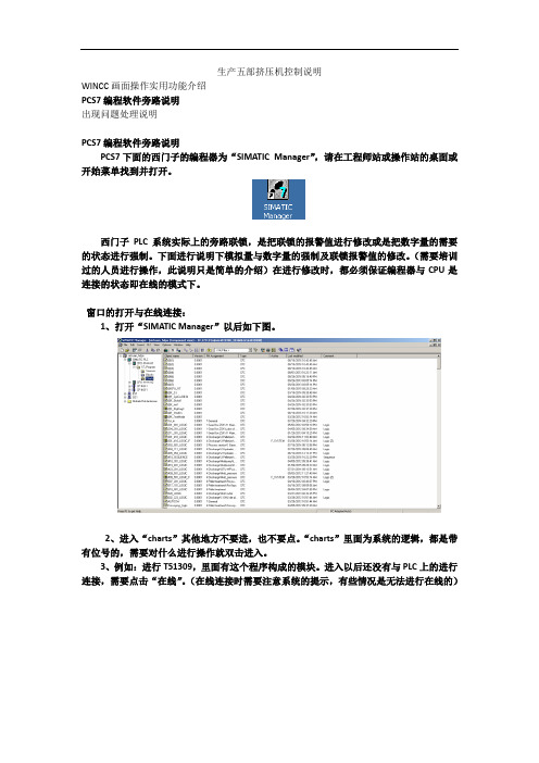
窗口的打开与在线连接:1、打开“SIMATIC Manager”以后如下图。
2、进入“charts”其他地方不要进,也不要点。
“charts”里面为系统的逻辑,都是带有位号的,需要对什么进行操作就双击进入。
3、例如:进行T51309,里面有这个程序构成的模块。
进入以后还没有与PLC上的进行连接,需要点击“在线”。
(在线连接时需要注意系统的提示,有些情况是无法进行在线的)在线4、在线连接以后,如果需要查看模块的管教实际值时,可以点击相应的管角,右键add i/o”即添加了当前的实际值。
“模拟量的强制及修改联锁报警值:1、首先要与CPU建立连接,也就是“在线”连接以后,点击查看模拟上的实际值。
2、如下图的模拟量模块,上面有俩个输入管脚“simon”、“simpv in”,这俩个管脚是仿真功能,可以把需要的值数字仿真进入系统。
在使用时要注意,先设置哪个管脚后设置哪个,“simon”为启用仿真功能,“simpv in”为需要强制的数值,在强制时,要先设置“simpv in”,在设置“simon”,在恢复强制时,要先设置“simon”,在设置“simpv in”这俩强制与恢复的顺序一定不能设置反了。
“simon”设置“1”为启用;“0”为解除;“simpv in”为想要的数值。
模拟量模块3、程序里面每一个模拟量模块的后面都会有一个报警设置模拟。
PCS7下冗余IO编程
PCS7下冗余IO 编程Redundant IO practice under PCS7V6.1 and PCS7V7.0摘要本文详细介绍了冗余IO 的原理,模板IO冗余和通道IO 冗余的区别。
在PCS7V6.1和PCS7V7.0下如何对模板IO冗余和通道IO 冗余进行硬件组态、冗余设置、CFC编程等。
关键词 PCS7 ,冗余IO,模板IO冗余,通道IO 冗余,组态Key Words PCS7 ,Redundant IO,Module-oriented redundancy, Channel-oriented redundancy , ConfigurationA&D Service & Support Page 2-65目录PCS7下冗余IO 编程 (1)1.概述 (5)2.PCS7V6.1下组态IO冗余 (6)2.1冗余模拟量输入 (6)2.1.1 示例系统的体系结构 (6)2.1.2 组态 (8)2.1.2.1 运行SIMATIC MANAGER 并创建一个新的项目 (8)2.1.2.2 AI 模件作冗余IO 时的设置说明 (8)2.1.2.3 AI 模件属性中冗余设置 (8)2.1.2.4 AI 模件属性中的输入设置 (9)2.1.2.5 AI 模件属性中地址设置 (10)2.1.2.6 在项目的plant hierarchy 中插入一个CFC 块 (11)2.1.2.7 对完成的CFC 进行编译,下载 (12)2.2 冗余模拟量输出 (14)2.2.1 示例系统的体系结构 (14)2.2.2 组态 (16)2.2.2.1 运行SIMATIC MANAGER 并创建一个新的项目 (16)2.2.2.2 AO 模件属性中的输出设置 (16)2.2.2.3 AO 模件属性中地址设置 (17)2.2.2.4 在项目的plant hierarchy 中插入一个CFC 块 (17)2.2.2.5 对完成的CFC 进行编译,下载 (18)2.3 冗余数字量输入 (19)2.3.1 示例系统的体系结构 (19)2.3.2 组态 (21)2.3.2.1 运行SIMATIC MANAGER 并创建一个新的项目 (21)2.3.2.2 使用DI 模件作冗余I/O 时的设置说明 (21)2.3.2.3 DI 模件属性中冗余设置 (22)2.3.2.4 DI 模件属性中的输入设置 (22)2.3.2.5 DI 模件属性中地址设置 (23)2.3.2.6 在项目的plant hierarchy 中插入一个CFC 块 (23)2.3.2.7 对完成的CFC 进行编译,下载 (24)2.4 冗余数字量输出 (25)2.4.1 示例系统的体系结构 (25)2.4.2 组态 (27)2.4.2.1 运行SIMATIC MANAGER 并创建一个新的项目 (27)2.4.2.2 DO 模件属性中的输出设置 (27)2.4.2.3 DO 模件属性中地址设置 (27)2.4.2.4 在项目的plant hierarchy 中插入一个CFC 块 (27)2.4.2.5 对完成的CFC 进行编译,下载 (28)3.PCS7V7.0下IO冗余编程 (29)3.1 冗余模拟量输入 (30)3.1.1 示例系统的体系结构 (30)3.1.2 组态 (31)3.1.2.1 运行SIMATIC MANAGER 并创建一个新的项目 (31)3.1.2.2 AI 模件作冗余IO 时的设置说明 (31)3.1.2.3 AI 模件属性中冗余设置 (32)A&D Service & Support Page 3-653.1.2.4 AI 模件属性中的输入设置 (32)3.1.2.5 AI 模件属性中地址设置 (33)3.1.2.6 在项目的plant hierarchy 中插入一个CFC 块 (33)3.1.2.7 对完成的CFC 进行编译,下载 (34)3.2冗余模拟量输出 (41)3.2.1 示例系统的体系结构 (41)3.2.2 组态 (42)3.2.2.1 运行SIMATIC MANAGER 并创建一个新的项目 (42)3.2.2.2 AO 模件属性中的输出设置 (42)3.2.2.3 AO 模件属性中地址设置 (43)3.2.2.4 在项目的plant hierarchy 中插入一个CFC 块 (43)3.2.2.5对完成的CFC 进行编译,下载 (43)3.3冗余数字量输入 (46)3.3.1 示例系统的体系结构 (46)3.3.2 组态 (47)3.3.2.1 运行SIMATIC MANAGER 并创建一个新的项目 (47)3.3.2.2使用DI 模件作冗余I/O 时的设置说明 (47)3.3.2.3 DI 模件属性中冗余设置 (47)3.3.2.4 DI 模件属性中的输入设置 (48)3.3.2.5 DI 模件属性中地址设置 (49)3.3.2.6 在项目的plant hierarchy 中插入一个CFC 块 (49)3.3.2.7 对完成的CFC 进行编译,下载 (50)3.4冗余数字量输出 (53)3.4.1 示例系统的体系结构 (53)3.4.2 组态 (54)3.4.2.1 运行SIMATIC MANAGER 并创建一个新的项目 (54)3.4.2.2 DO 模件属性中的输出设置 (55)3.4.2.3 DO 模件属性中地址设置 (56)3.4.2.4 在项目的plant hierarchy 中插入一个CFC 块 (56)3.4.2.5 对完成的CFC 进行编译,下载 (56)4.小结 (58)5.附表 (63)附表1 支持冗余IO的模块 (63)附表2 数字量输出模块内部集成/非集成二极管 (64)附表3 支持通道IO冗余的模块 (64)A&D Service & Support Page 4-651.概述冗余I/O的定义:当系统包含两套模块,且这些模块被组态为冗余对并作为冗余对操作时,即被视为冗余I/O 模块。
- 1、下载文档前请自行甄别文档内容的完整性,平台不提供额外的编辑、内容补充、找答案等附加服务。
- 2、"仅部分预览"的文档,不可在线预览部分如存在完整性等问题,可反馈申请退款(可完整预览的文档不适用该条件!)。
- 3、如文档侵犯您的权益,请联系客服反馈,我们会尽快为您处理(人工客服工作时间:9:00-18:30)。
SIEMENS PCS7冗余IO在山东海化苯胺项目中的应用
工程部杜家全
一.系统概况
5万吨/年苯胺装置,是山东海化股份有限公司天祥化工厂继8万吨/年甲烷氯化物及10万吨/年乙酸乙酯装置之后的又一重要装置;DCS系统仍采用SIEMENS PCS7 V6.1SP1。
DCS系统结构如下:
DCS 系统采用了冗余控制器:2套CPU 417-4H(仪表部分)、1套CPU 414-4H(电气部分);并采用了冗余IO,包括AI冗余、AO冗余、DI冗余、DO冗余。
冗余控制器及冗余IO的结构示意如下:
如下为仪表部分第一个控制器及其IO组成示意图:
二.冗余IO
1.AI冗余(6ES7 331-7KF02-0AB0)
AI冗余分为带有冗余传感器的冗余模拟量输入模板方式:
和接入非冗余传感器的冗余模拟量输入模板方式:
在本项目中,模拟量输入为4-20mA信号,传感器不冗余,AI卡件为6ES7 331-7KF02-0AB0,故采用了第二种方式中的间接电流测量方式。
1.1 硬件设计
下图为接线原理图:
由于一个信号要接入两个卡件,所以我们采用了冗余端子,AI冗余端子结构如下(冗余端子可由柜厂订做或者向有资质的第三方购买):(R1、R2为250欧姆)
当信号为4-20mA 2线制时,接线方式如下::(CH1+/CH1-接入主卡件相应通道,CH2+/CH2-接入备用卡件相应通道)
当信号为4-20mA 4线制时,接线方式如下:(CH1+/CH1-接入主卡件相应通道,CH2+/CH2-接入备用卡件相应通道)
1.2 组态设置
设置控制器过程影像分区:
卡件冗余设置:
输入设置,在本项目中测量类型应为1-5V电压类型而非4-20mA电流型:
地址设置,过程影像区设为PIP1:
1.3 CFC
在CFC中,只需对冗余IO的低地址进行组态,可以认为高地址的卡件不存在;且冗余IO的驱动块必须放在和卡件过程影像区对应的OB中,否则有可能出现信号不稳定。
本项目中,卡件过程影像区为PIP1,对应的OB为OB35,所以驱动块应放在OB35中。
1.4 注意
AI冗余输入,采取一主一备的工作方式,始终只有一个卡件(或通道)输入,当主卡件(或通道)故障时,备用卡件(或通道)开始工作,存在切换时间,在切换瞬间,信号有毫秒级时间的跳变。
当0、2、4、6通道故障时,1、3、5、7通道将不能进行正常冗余切换,因此没有使用的1、3、5、7通道应短接起来以形成回路,不过当1、3、5、7通道故障时,0、2、4、6通道冗余切换不受影像。
2.AO冗余(6ES7 332-5HF00-0AB0)
AO冗余原理示意图如下:
2.1 硬件设计
AO冗余端子原理及接线图示如下:
2.2 组态设置
卡件冗余设置:
输出设置:输出为4-20mA电流型:
地址设置:过程影像区设为PIP1:
2.3 CFC
同1. 3部分。
2.4 注意:
AO冗余输出,采取主备卡件(或通道)同时工作各输出一半的工作方式,当一个卡件(或通道)故障时,另一个卡件(或通道)完全输出。
即:当一个冗余通道要输出20mA时,低地址的通道和高地址的通道各输出10mA,当低地址的通道故障(包括所在卡件故障)时,高地址输出20mA;反之亦然。
在切换过程中,整个输出会瞬间减小至原输出信号的一半再迅速变为正常。
3.DI冗余(6ES7 321-7BH01-0AB0)
DI冗余分为非冗余传感器的数字量输入模板方式:
和带有冗余传感器的数字量输入模板方式:
本项目中,我们采取了第一种方式。
3.1 硬件设计
通过继电器把一副触点转换为两副触点,分别接入主备的两个卡件;在转换过程中,继电器线圈要串入24V电源。
3.2 组态设计
类同于1. 2。
3. 3 CFC
类同于1. 3.
3. 4 注意
DI冗余采取的是一主一备的工作方式,类似于AI冗余,存在切换的问题。
4.DO冗余(6ES7 322-8BF00-0AB0)
通过并行连接两个数字量输出模板或安全型数字量输出模板的两个输出可以实现执行器的冗余控制。
本项目中由于DO卡件每个通道本身带有二极管,故无需另加二极管。
3.1 硬件设计
把主备两个通道的输出,分别输出到各自的继电器,再把两个继电器的输出并联后输出到执行器。
3.2 组态设计
类同于2. 2。
3. 3 CFC
类同于2. 3.
3. 4 注意
DO冗余采取的是主备同时工作的工作方式,主备通道的输出始终是一致的,因此不存在切换的问题。
三.应用体会
SIEMENS PCS7 IO冗余在山东海化股份有限公司天祥化工厂甲烷氯化物装置、苯胺装置及乙酸乙酯装置中得到了很好的应用,并根据实际情况,做了很多尝试,达到了用户的冗余要求。
这说明PCS7 冗余系统特别是IO冗余部分有了很大改进,但要真正实现冗余,达到安全要求,还需要项目工程师根据具体项目具体要求,进行细致的分析,并给出切实可行的方案。