1825010-6中文资料
UL 1026-中文版

UL 1026前言A.此標準包括目錄範圍內覆蓋UL公司產品后續服務的基本要求, 這些要求是基于成熟的工程原理, 研究, 測試記錄現場試驗及生產安裝問題的認識, 從廠家, 用戶, 檢驗機構其它專業經驗咨詢時所獲取的信息, 如有必要他們可以進一步實驗調查后改正.B.此標準的觀察要求是持續保證生產廠家產品的條件之一.C.按這些要求在檢查或測試產品時, 只要產品符合此標準, 即使發現預料的其它安全損害, 也可視為符合標準.D.產品采用的材料或者其結構形式與此標準中的要求有些區別, 那么可以按照設計要求測試, 如果大部份材料相同, 那么就可以按照標準進行判斷.E.UL在按照目標進行功能演示時, 不能下放廠家或其它任何部門的責任, 標準在制定時, UL的意見和調查研究結果, 已經代表了專業評判標準, UL對任何使用或依賴下標準不負任何責任, UL不會發生任何責任義務損害, 包括由于使用, 解釋或依賴此標準產生的重大損壞.F.按照UL要求進行測試時有一些不可避免的損害, 因此在進行測試時采取足夠的安全措施和足夠的防護工具是必要的.1.範圍1.1.這些要求覆蓋了在普通情況下使用的250V或以下的家用廚具電器(除了1.2里有說明外),包括臨時或永久地在戶外使用的家用廚具電器應符合國際電器條例規定.1.2.這些要求不包括家用電器系列, 電極型, 長柄鍋及電炸鍋, 乳酪機鍋, 面拖油炸機, 爆谷機, 咖啡壺, 電飯鍋, 微波爐, 以及按個人要求制作的電器不包括在此標準內.1.3.以下內容中, 確定是否符合此範圍內的一種裝置的要求(如多士爐和類似的)應通過具體參考此型號要求, 在沒有具體參考資料時,如果采用"符合"條款, 那么條款應為公認符合標準所有型號的要求.1.4.產品包括外形特點, 零件, 系統更新及與此標準要求有區別的產品,而涉及到火險, 電擊, 傷人應該使用適當的附加零件進行測試, 其安全水平的最后結果應保留在標預期的範圍內, 產品外型, 特性, 零件, 材料, 系統與具體要求相衝突, 不能視為符合此標準, 如果考慮提出修改要求, 應采用一致的方法, 開發, 修正, 執行此標準.2.組合件.2.1.除2.2說明外, 此標準中產品組合件應符合組合件的要求, 如產品一般使用標準組合件清單索引A所示.2.2.組合件不需要與具體相符是:a.此標準包括的產品應用中不必涉及到外形或特性.b.由此標準要求代替.2.3.組合件應在認可的設計環境下使用.2.4.結構中的些特殊組合件不全面或限制其性能發揮, 這些組合件只能在限定環境下使用, 例如不超過一定限定溫度下使用且只有在認可的選定環境下限制使用.3.裝置的測量:3.1.指數必須說明, 括號里的指數為解釋或相近信息.4.參考材料4.1.此標準要求的條例或標準的任何要求更新應被解釋為最新的條例和標準.結構5.總則.5.1 如果電器在運行時會產生或在有氣體或其它氣體壓力下運行, 考慮到爆炸事故的可能性, 因此電器不能算合格, 除非電器有足夠強度抵禦爆炸危險.6.框架與外殼.6.1.電器的框架和外殼應該足夠的張度和鋼度抗拒正常使用中可能的濫用, 但不要因電器固有的抵抗強度而減少電器的空間, 產生松動, 零件錯位而導致部分或全部失效或者結構組合時而增加火險, 電擊或傷害的危險.6.2.電器外殼材料應該能夠隨特殊用途, 能夠容納所有電器零件, 除電源線和14.3,14.4中在任意環境下使用時可能會引起火險, 電擊或傷害的裸線元件外, 如果電器要與電源永久聯接時, 電器外殼應提供用于安裝所必需的裝置, 如: 托架, 挂鉤或類似物.6.3.在正常工作狀態中需要加油的電器, 應特別考慮在烹調腔上加一個外殼, 外殼的材料也應適合此目的.6.4.電器外殼采用通風開口或在外殼上安裝永久電源聯接元件的電器,其位置不能讓排氣進入封閉結構的空間, 如活動頂的空間, 壁洞空間或類似空間.6.5.判斷電器外殼性能時應考慮的因素是:a.物理強度.b.抗衝擊強度.c.吸水汽性.d.可燃性.e.防腐蝕性.f.在高溫下抗變形能力, 外殼在正常和非正常情況下使用的承受能力.對于非金屬材料外殼要求可參考<<電氣設備評估>>UL746C的聚合物標準, 金屬外殼零件或外殼應按照<<金屬外殼衝擊測試>>42節進行抗衝擊能力測試.例外情況1. 考慮按UL746C進行濫用和惡劣條件測試時, 電器外殼應按此標準中濫用運作測試的第44節進行判斷.例外情況2. 因加硬化材料要按43.1要求在高溫下連續1000小時老化測試, 所以加熱硬化材料不需要符合UL746C要求..06.6.采用過熱保護的熱塑外殼電器, 如果采用94HB材料, 具有至少60弧抵抗高電流弧光點火, 至少7秒鐘抗熱點火, 及外殼所有零件包括, 肋骨, 煎件或類似零件相距至少1/2" (12.7mm)那么可燃性要求可不一定要符合UL746C.6.7.除非電器外殼如6.5和6.8判斷認為合格, 否則電器外殼的鑄造和鐵片部分厚度不能小于表格6.1所示.6.8.除了考慮6.5中所提及的因素外, 考慮到電器的設計用途, 外殼金屬片也要考慮其尺寸, 形狀, 厚度和特殊應用能力.6.9.為防止發生無意識與導電零件接觸, 電器上的導電零件, 除自動焗燼裸線元件的發光部分以外, 其位置或包起來保護, 絕緣馬達刷帽不要求額外附件.表6.1金屬外殼的最小厚度6.10外殼構造應該讓熔化金屬, 防火物, 或類似物不會落在支撐面上6.11在6.10必須要求中, 外殼底部開口處的上面或下面必須有隔板, 如果開口為:a.在馬達下面時應:1).馬達的結構零件或電器提供類似的隔板.2).馬達在以下缺陷條件下通電時, 馬達這種保護措施是為了防止燃燒絕緣物或熔化物落在電器的支撐面上.i) 開主線圈.ii)打開起動線圈.iii)啟動短路關.iv)永久分開電容器的馬達為短路電容器, 在馬達通電前和回轉輪被堵時進行短路通電.3).采用熱發動機保護器(同時感應溫度和電流的保護裝置)的發動機是防止發動機線圈在最大負荷的內溫度不超過125℃(302ºF).4). 采用的馬達符合阻抗馬達要求.b.在電線下, 除非電線符合電線, 電纜, 伸縮線UL1581參考標準VW-1燃燒測試或者垂直燃燒測試.c.在無蓋開關, 變壓器, 螺線管或類似物下面, 除非馬達零件不會因為著火而引起故障.d.在電場和工廠制造的拼接過載, 過載電流保護裝置.例如: 如圖6.1D線所示, 如果開口不在組合件下面範圍內, 可以不用隔板.圖6.1隔板呎吋與位置A-隔板遮蓋的範圍,如果組合件沒有被遮蓋,則由整個組合件組成和一個組合件未遮蓋部份(被組合件外殼遮蓋的部份)組成.B-投影在水平板上組合件的輪廓C-隔板傾斜線軸軌跡最小範圍,傾斜線總是1)與零件的切線2)與垂直線5度,和3)水平面的定向軌跡是最大的D- 為隔板最小範圍和位置(水平位),範圍包括傾斜線C和隔板水平面軌跡交叉線6.12於6.11中所提及的擋板應是a)金屬,陶瓷,或作為外殼符合6.5可以接受的原料.b)水平的c)位於圖6.1指示的位置,不應小於圖6.1所描述的位置.6.13 如果在圖6.2中說明的探針通過開口插入不能接觸能引起水險或電擊的任何非常絕緣帶電部件,則在外殼中的開口有小於1英吋(25.4mm)的較小呎吋是可以接受的.探針在插入前、後及過程中適用於所有可能連接的位置.6.14如果在外殼內部沒有非絕緣體或用膠膜包裹的電線,則如圖6.3說明的外殼開口最小呎吋為1英吋或更長一點是可以接受的.R表示至開口周圍里邊的距離,X表示至開口平面的距離,T等於外殼的厚度,R等於X 加T,X等於能插入開口圓桿最大直徑的5倍,但不小於6-1/16英吋(154毫米).在測定開口的過程中,任何在容積範圍內的擋板是可以被忽略的,除非它持續橫切容積邊緣.6.15為了恆溫器的調整或類似的行動,如果在外殼上作一個引起用戶註意的任意大小的孔,不能破壞絕緣體或用直徑為1/16英吋(1.6毫米)插通過孔接觸非絕緣體.6.16關於在6.9和6.13-6.15中的要求,在電器的檢查過程中,外殼的任何部份可被忽視(打開或移動)那是受到的保護能防止電擊或傷人的部份.或如果a)外殼用或不用工具打開或拆卸以執行制造商推薦的用戶服務、維修、操作調整.配件連接或其它操作.b)不用工具能打開或拆卸,見6.16.1例外:如果電器標記與54.9一致,外殼的一部分要求用工具打開或拆卸以執行制造商推薦的用戶服務、維修、操作調整、配件連接或其它操作以保持保持其位置.6.16.1關於6.16(b),為确定外殼或外殼的一部份要求使用工具打開或移動,依靠非金屬部件機械穩固的外殼或外殼的一部份,如塑膠挂耳或快速連軸節插人物或插桿應遵照42A節非金屬外殼緊固器測試.例外:完全通過金屬緊固器(如鏍絲或鉚釘)穩固外殼或外殼的一部份到其它外殼部份,則不需經受此測試.6.17任何活動零件, 例如馬達回轉輪, 鏈條, 滑輪, 帶子和齒輪應褢起來或監視以減少對人的傷害.6.18參照6.17要求, 外殼的保護程度取決于總結構和電器的用途, 以下為判斷裸露活動零件能力應考慮的因素.a.外殼強度b.活動零件的銳利程度.c.無意識與導電零件接觸可能性.d.這些零件移動的速度.e.手指, 手臂或衣服被卷入活動零件的可能性.6.19外殼上的門或蓋上應有手柄以確保進入關閉位置6.20為方便更換過蠛保護裝置或當有需要開蓋操作保護裝置, 外殼上的門或蓋應用絞鏈連接.這些門或蓋應有插銷, 配合緊湊或與外殼表面開口有重壘.6.21電器零件無需用特別工具(不是服務人員就難得到的工具)如果是由人工操作, 調節或定期維護的電器.6.22如果試管或燈泡壞了會嗇火險, 那熱偶的燈泡或毛細管應可以保護電器不被破壞.7組裝7.1 如果電器上有開關, 可連接插頭型插座或插頭型連接器安裝要可靠防止因表面摩擦而使零件產生反轉(動).7.2 為防止裝柄開關轉動可采用鎖墊圈.7.3如果導電零件因附重壓而轉動或轉移而減少零件之間空間低于26.1.1.1-26.1.1.4的要求, 那么導電零件應固定在基面上.7.4 防止導電零件轉動或轉移, 導電零件之間的表面不能產生摩擦可使用鎖墊圈.8. 穩定:8.1 電器的穩定性, 不能因正常使用情況電器很容易傾倒.8.2 家用烹調或熱電器可以輕易用手提或搬運(如矮電器, 食品加熱器或類似的)電器裝上至少50盎司(148ml)水, 加熱到115ºF(46ºC)溫度, 放在與水平面15º的傾斜面上, 無論裝上全部的拆分件, 液體或其它材料, 電器應符合設計使用的最大傾斜角傾倒要求, 電器不會產生滑動, 不能因測試而傾倒.9. 防腐蝕保護9.1 如果因未保護零件的故障增加著火或電擊危險的鐵和鋼片應以瓷釉法, 鍍鋅,電鍍或其它的方法以保護.例外: 某些設備中的氧化鋼不會因為金屬暴露在空氣, 水汽或其它氧化而影響使其加快氧化的金屬其厚度和溫度也是考慮因素, 無需保護, 外殼內金屬片表面要求防腐蝕保護. 鑄壓零件不要求防腐蝕保護, 采用保護套的加熱件和直接連接加熱件的終端零件不需防腐蝕保護.9.2 電器里電鍍或其它處理具有老化性質的零件不能在最后壞至電器不能使用的程度.10. 電源聯接10.1 永久性連接電器10.1.1總則10.1.1.1除10.1.1.2中注明外, 電器采用永久電源聯接設計, 應符合國際電器條例ANSI/NFPA No.7-1993要求.10.1.1.2如果采用活動短電線和可連接插頭作為電源聯接的電器, 可以固定在特點空間. 這種特征的電器還應考慮到電器的應用性, 和電器可連接電源插頭應容易拆開.10.1.1.3 電器按設計要求安裝以后, 終端的位置或永久聯接電器與電源隔板的這些聯接應檢查方便.10.1.1.4 聯接電源保護管的終端間隔與電器的聯接不會產生轉動. 10.1.2 電場電線終端.10.1.2.1 永久聯接電源電器應該采用電線終端或當電流量不低于電器電流量, 連接導體的安載流量不少于電器電流的125%時, 負載邊3小時或以上時這時負載將時斷時續.10.1.2.2 為符合這些要求, 電路終端應為電源接頭或當電器安裝時現場聯接控制.10.1.2.3 電線終端應采用焊接接合, 或可以將電線聯接器牢固地壓入合適位置(如用插銷或螺釘穩固)如果向上接合或類似方法使電線固定, 電線終端容納10AWG(5.3mm2)或更小的導體可以采用線綁螺釘固定.10.1.2.4 電線終端應防止轉動或旋轉, 除表面摩擦外, 可以用兩個螺絲,鉚釘或其它類似方法固定.10.1.2.5 電線終端上的線綁螺釘不能小于10號, 除8號螺釘可以使用在14AWG(2.1mm2)或更小導體的終端聯接中, 6號螺釘可以使用在16AWG(13mm2)或更小的控制電路導體中.10.1.2.6 叩入綁線螺釘的終端金屬片不能小于0.050”(1.3mm)除叩擊螺紋線有相同的機械強度可用于小于0.030”(0.8mm)厚度的金屬上. 如果需要螺紋線伸出金屬上可用雙根螺紋線.10.1.2.7 突出接合處或杯形墊圈可保持導體的能力如果其尺寸為10.1.2.1在螺帽或墊圈下的導體不能小于14AWG(2.1 mm2)10.1.2.8 線綁螺釘應穿入金屬中.10.1.2.9 接地電源導體聯接的電器應:a.Edison螺帽型的燈頭或元件容器.b.單柱開關, 或c.單柱自動控制應有一個終端或頭以確認電源電路接地導體. 除在24.2中說明外, 終端或頭到燈頭或元件容器的螺帽殼視為一個整體, 不是聯接到單柱開關或單柱自動控制器.10.1.2.10 接地聯接電路導體的終端應用白色金屬制成或鍍成白色, 使之非常容易與其它終端與辨出來, 或以其它方法使之容易分辨,如在線路圖上標注, 接地電路導體的頭也要用白色或灰色, 使之與其它頭容易分辨.10.1.2.11 除10.1.2.12說明外, 內部的插座盒或電線間隔長度應為6"(152mm)或以上, 如果頭聯接電場與電路外圍.10.1.2.12 如果有跡象顯示, 使用長頭可能導致火險或電擊, 頭的長度可以少于6"(152mm).10.1.2.13 只聯接設備接地導體的絕緣頭的表面, 應用涂上綠色或黃綠相間的斜帶, 其它頭不必如此.10.1.2.14 聯接設備接地導體的六角形, 溝槽形或都是的綁線螺如應為綠色, 聯接這種導體的壓力電線聯接器應標記"G" "GR""GROUNDING"或類似的或標記在加熱電器上的線路圖里, 以便于區分, 綁線螺絲或壓力電線聯接器位置在電器維護時不會被移動.10.1.2.15 只聯接接地設備導體的終端應能確保特殊電器導體的適當尺寸.10.2 線聯接電器10.2.1 總則10.2.1.1線路聯接電器(用伸縮線路聯接電源電路的一種電器)應有一根電源線聯接電源電路或應有容納可拆或電源線的雄針終端,連接線或分拆線的長度按10.1所示.10.2.1.2線路聯接電器的線路電流量和電壓, 配件不能小于電器的標準, 當電器負載續運行3小時或以上時, 聯接插頭電流量不能小于125%電器電流量.10.2.1.3 電器中的可連接伸縮線和在可拆開電源線的型號應按10.2表格所示, 或其特性至少應能適應特定用途.10.2.1.4 當燒烤器使用在焗爐里時, 焗爐應采用可拆式或電源線, 焗爐和燒烤器都應采用無附件可拆式電源線.10.2.1.5 加強絕緣, 如果采用伸縮線長度不能超出電器外1/2"(13mm)如超出此長度, 應采取機械保護, 防止磨損或松脫, 減少拉緊力產生的不利影響.10.2.1.6 電器不能采用A3-2線制, 接地型接頭.10.2.1.7 15-20A電源線連接插頭的電器一般用3線接地型插座, 開合電器采用的電源線可聯接插頭應該可手工操作, 線聯單柱開關,或是極化或接地型螺口燈座燈柱.10.2.1.8 采用線接地型聯接插頭或2線型極化聯接插頭應符合圖10.1,伸縮極化確認應符合表格10.3要求.10.2.1.9 接地電源導體以下因素也要考慮在里面.a.螺口燈座柱的螺絲殼.b.插座接地終端或頭.10.1為接地電源線確認表.10.2.2 緩解拉力10.2.2.1 緩解拉力應防止聯接伸縮電源線上的機械力傳至終端, 絞接處, 或內線上.10.2.2.2 如果使用材料, 壓力板或其它纖維確保拉力緩解裝配, 纖維材料應用別針, 固定螺釘或其它有效方法予以固定.10.2.2.3 應采用一些措施防止聯接伸縮線通過線入口被壓入電器外殼里面, 確認是否符合此要求, 電源線或頭應按照Push-BackRelief40節A進行測試.10.2.2.4 用電線夾綁緊軟皮線,任何表面可以自由從,邊緣,批鋒,以便導致絕緣導電體擦損.10.2.2.5 當測量結果與10.2.2.6相符時, 伸縮線上的壓力緩解結在斷開電源狀態下以35Lbf(156N)拉線, 應能支撐1分鐘, 無錯位.10.2.2.6 電器結構的電線允許特定力量和從不同角度的拉線. 導體的斷開點, 結果顯示電線移動有足夠連接力.10.2.3 終端針10.2.3.1 如果電器采用終端針, 電器把插頭插在針上時或插上后, 不能使導電零件產生無意識的接觸.10.2.3.2 針護套要求如a.直線邊緣放在任何位置,交叉,與連接插頭開口(插頭沒有插在里面)邊接觸時, 不能與通電的終端針接觸.b.插頭與指針在同一條直線, 板上的插頭與未端或與通電指針成直角,當管道插入任何位電器的開口時, 管道(如圖6.2)不能接觸任何通電指針.10.2.3.3 符合10.2.3.2(b)要求的插頭可以隨附電器.10.2.3.4 采用3個以上的針終端, 并覆蓋所有的指針的電器插頭, 終端的空間不能容納一個熨斗插頭或線聯插頭或導體主體, 這些插頭針應適應于特定電器.10.2.3.5 如果電器采用用戶可拆加熱元件, 這些加熱元件應有如下保證:a.安裝可靠安全耐磨和b.加熱針防止被破壞, 縮短, 當在插入或拆出和彼此更換位置時.10.2.3.6 針終端應安全, 嚴格安裝防止摩擦而產生位置更換.10.2.3.7 10.2.3.6的要求主要是提供空間維護, 說明如26.1.1.1表格26.1和26.2里, 針終端之間保持適當空間. 在此要求中, 還要考慮保持鎖住終端的緊密性方法.10.2.3.8 針的尺寸, 中點與中點之間的距離, 包括一般使用插頭的接觸片之間的相應空間, 采用這些針的規格如10.4所示.10.2.3.9 采用兩針終端的電器不能使用可拆三導體或電源線作為接地導體.10.2.4 杯士10.2.4.1 軟皮線在通過牆隔板或密封盒的任一點時,將有一個杯士或相等同的固定,應光滑,圓渾的表面,如果SP-2, SPT-2型或采用其它比HSJ型輕的伸軟皮線, 如果牆或隔板為金屬, 軟皮線可能要承受拉力或移動時, 絕緣的杯士, 特殊用途的電器套管采用的材料應能隔熱, 抗水汽的特性.10.2.4.2 如果線孔是木材,陶瓷,電木粉成份或其它不導電材料構成,套管的表面應光滑, 圓渾相等同的杯士.10.2.4.3 絕緣套管通常可采用陶瓷材料和一些鑄模結構, 但不能采用,木材, 熱模紫膠, 瀝青, 橡膠等材料的單套管. 如果套管厚度不小于3/64"(1.2mm)在一般水汽條件下不會產生不利影響可采用硬化纖維材料.10.2.4.4 單個的軟橡膠, 氯丁橡膠管套可采用在馬達框架上或邊接馬達的容器外殼(除10.2.4.5說明外不能使用在電器其它地方)且:a.套管厚度不能少于3/64"(1.2mm)b.套管位置不能暴露在油, 油脂, 油性氣體或其它對化合物有破壞影響的物質中.10.2.4.5 如果絕緣連接導管伸縮線無型號要求, 10.2.4.4中所提及的套管的任何材料可以使用在電器中任何部位, 安套管洞口邊光滑無毛邊, 鰭或類似物時.10.2.4.6 如果使用的絕緣材料厚度少于1/32"(0.8mm), 能完全填住安裝金屬的孔眼, 絕緣套管里可以采用絕緣金屬墊圈.11. 通電零件.11.1每一個通電零件所采用的材料應適合特殊用途.11.2通電零件可用抗腐蝕合金做成(如不鏽鋼)不能用普通鐵和鋼做成, 除非這些材料經過表面處理及產生抗腐蝕能力, 即使這樣也適用于:a.針終端b.終端零件, 馬達的其它零件, 馬達控制器.c.正常溫度下操作時超過100°C(212°F)的零件.d.鍍膜鐵和鋼件局部的部件要求參照2.1節所示.11.3 帶水槽的電器, 所有的活動零件其位置或要保護起來而不會因為水槽壞了而掉下來, 除非:a.水槽能抗使用液體腐蝕, 和b.水槽不會因老化而破裂.12. 內線12.1 總則12.1.1電器的內線尺寸, 型號應適用于特殊用途, 并考慮以下特性:a.電線可能承受的溫度和電壓.b.暴露在油或油脂中, 和c.可承受的其他環境.12.1.2玻璃纖維, 無機材料或類似材料作為導體絕緣材料無溫度限制.12.1.3電器內部采用的熱塑絕緣電線應為標準的建築電線, 混合電線或適用于特殊用途的電器電線材料.12.2 電線保護12.2.1線路和零件之間的聯接應予以保護或封閉, 除外部聯接的伸縮線外, 或因為電器使用時可能暴露內部聯接, 線路必須是活動的除外, 絕緣的裸導體或帶珠導體不能在外殼外使用.12.2.2穿過電器外殼開口處而露出的內部線路的保護要求如122.1當認為有鍍膜需要的線路應符合6.9-6.13要求. 內部線路在外殼內不會承受壓力或機械損壞可不需要保護.12.2.3如果電器線路的位置可能靠近可燃材料或機械傷害的線路要用彩盔甲電線或在鋼管, 電子金屬管, 金屬保護里, 或其它保護..12.2.4外殼, 零件, 保護管或類似物內的線路其位置或被保護, 而不會因為接觸任何粗糙, 尖銳或活動零件而損壞導體的絕緣體. 12.2.5絕緣電線通過電器外殼內金屬牆洞口時, 應用一根光滑的導管,或電線通過的表面應光滑圓渾, 以防止絕緣體被擦壞. 如12.2.1用伸縮線作內, 外聯接應按照10.2.2.1-10.2.2.6和10.2.4.1-10.2.4.6進行拉力解緩和采用套管, 除非伸縮線的結構可抗拒拉力和移動, 例外10.2.6 絕緣電線可以扎成束穿過電器外殼內金屬牆洞口.12.3 絞接(疊接)12.3.1所有的絞接和聯接機械性能應可靠, 電子件接觸應應適應, 如果由于聯接的破裂或松動可能引火險或火擊時, 在確保可靠機械性能下可進行死聯接.12.3.2如果絞接處與其它金屬零件之間的距離不能永久保持, 那么絞接處也要采用與電線一樣的絕緣.12.3.3絞接處的絕緣由兩層摩擦帶, 兩層熱塑帶或一層摩擦帶在一層橡膠帶上組成, 考慮其絕緣性, 抗熱性, 抗水汽性, 絞接處絕緣材料可由纖維, 熱塑片或其它型號管子構成. 但熱塑帶不能包尖銳邊.12.3.4連接綁線螺絲和內部線路, 應絕對防止與其它任何同樣極化的導電是線接觸, 與任何死區金屬零件接觸. 可使用壓力終端連接器, 焊接接合, 折皺視孔, 氫所有的電線焊接在一塊或其它類似方法達到目的.12.4分開電路.12.4.1 總則12.4.1.1除非絕緣導體提供最高電壓絕緣, 否則電路絕緣導體分開聯接電源應用隔板隔開, 或單獨聯接電源, 除12.4.1.3說明外,電路上的絕緣導體應為單獨的或與其它不同線路導電零件和絕緣零件分開.12.4.1.2絕緣導體的分開可采用夾, 路線, 或類似能與不同電路的絕緣和導電零件永久分開的方法.12.4.1.3 任何電路的現場安裝導體應隔與….分開.a.現場安裝導體和工廠導體與其它任何電路的聯接, 除非兩個電路導體與每個電路最大電壓絕緣. 和b.電器中任何其它電路的導電零件與任何導電零件的短路將會導致火險, 和電擊, 除…1). 電場安裝導體的結構型或為T, TF型時或安裝的相似導體可。
BS EN 15081-2007 工业阀门.部分回转阀门传动装置附件用装配工具箱

BS EN 15081-2007 工业阀门.部分回转阀门传动装置附件用装配工具箱actuator attachmentThe European Standard EN 15081:2007 has the status of a British StandardICS 23.060.99Industrial valves —Mounting kits for part-turn valve BS EN BRITISH STANDARD15081:2007BS EN 15081:2007This British Standard was published under the authority of the Standards Policy and Strategy Committee on 31 October 2007?? BSI 2007ISBN 978 0 580 54764 5Amendments issued since publicationAmd. No. DateCommentsCompliance with a British Standard cannot confer immunity from legal obligations.National forewordThis British Standard is the UK implementation of EN 15081:2007.The UK participation in its preparation was entrusted by Technical Committee PSE/7, Industrial valves, to Subcommittee PSE/7/1, Valves —Basic standards.A list of organizations represented on this committee can be obtained on request to its secretary.This publication does not purport to include all the necessary provisions of a contract. Users are responsible for its correct application.标准分享网 .bzfx免w费.c下o 载mEUROPEAN STANDARDEN 15081NORME EUROP ENNEEUROP??ISCHE NORMOctober 2007ICS 23.060.99 English VersionIndustrial valves - Mounting kits for part-turn valve actuatorattachmentRobinetterie industrielle - Kits de montage pourIndustriearmaturen - Montages tze f r Anschl sse vonraccordement des actionneurs fraction de tourSchwenkantrieben an ArmaturenThis European Standard was approved by CEN on 26 August 2007.CEN members are bound to comply with the CEN/CENELEC Internal Regulations which stipulate the conditions for giving this EuropeanStandard the status of a national standard without any alteration. Up-to-date lists and bibliographical references concerning such nationalstandards may be obtained on application to the CEN Management Centre or to any CEN member.This European Standard exists in three official versions (English, French, German). A version in any other language made by translationunder the responsibility of a CEN member into its own language and notified to the CEN Management Centre has the same status as theofficial versions.CEN members are t睷he national st眮andards bodie抵s of Austria, 晸Belgium, Bulg眮aria, Cyprus,捯 Czech Repub?lic, Denmark, Estonia, Finland,France, Germany, Greece, Hungary, Iceland, Ireland, Italy, Latvia, Lithuania, Luxembourg, Malta, Netherlands, Norway, Poland, Portugal,Romania, Slovakia, Slovenia, Spain, Sweden, Switzerland and United Kingdom.EUROPEAN COMMITTEE FOR STANDARDIZATIONCOMIT EUROP EN DE NORMALISATIONEUROP??ISCHES KOMITEE F R NORMUNGManagement Centre: rue de Stassart, 36 B-1050 Brussels' 2007 CENAll rights of exploitation in any form and by any means reservedRef. No. EN 15081:2007: Eworldwide for CEN national Members.EN 15081:2007 (E) Contents Page Foreword............................................................. ..................................................................... ............................3 1 Scope................................................................ ..................................................................... .................4 2 Normative references........................................................... .................................................................4 3 Terms and definitions.......................................................... .................................................................4 4 Design requirements......................................................... .. (5)4.1 General.............................................................. ..................................................................... .................5 4.2 Materials............................................................ ..................................................................... ................5 4.3 Design temperature.......................................................... .....................................................................6 4.4 Environmental corrosion protection........................................................... .........................................6 4.5 Mounting kit.................................................................. ..................................................................... .....6 4.6 Coupling............................................................. ..................................................................... ...............7 4.7 Designation.......................................................... ..................................................................... .............7 4.8 Position indicator............................................................ ..................................................................... ..8 4.9 Buried service.............................................................. ..................................................................... .....8 4.10 Safety requirement (mechanical/thermal protection).......................................................... ..............8 4.11 Orientation.......................................................... ..................................................................... ...............8 4.12 Additional anti-rotation means................................................................ .............................................8 4.13 Valve/actuator 睷package m眮aintenanc抵 e..............晸.................眮..................捯.................?................................8 5 Dimensions........................................................... ..................................................................... .............9 5.1 Bracket.............................................................. ..................................................................... .................9 5.2 Valve top flange............................................................... .. (1)0 5.3 Coupling............................................................. ..................................................................... .............10 5.4 Spools and adapter flanges.............................................................. ..................................................12 6 Marking.............................................................. ..................................................................... ..............12 6.1 General.............................................................. ..................................................................... ...............12 6.2 Mandatory information.......................................................... ..............................................................12 6.3Optional information.......................................................... .................................................................12 7 Documentation........................................................ ..................................................................... ........12 7.1 Language............................................................. ..................................................................... ............12 7.2 Product documentation........................................................ .. (12)Annex A (normative) Coupling axial clearance............................................................ ..................................13 Annex B (informative) Proposed stem details for ball and butterfly valves................................................15 B.1 General.............................................................. ..................................................................... ...............15 B.2 Proposed stem details for ball valves............................................................... ................................16 B.3 Proposed stem details for butterfly valves............................................................... (16)Bibliography.............................................................................................................................. ........................18 2 标准分享网 .bzfx免w费.c下o载mEN 15081:2007 (E) Foreword This document (EN 15081:2007) has been prepared by Technical Committee CEN/TC 69 “Industrial valves”, the secretariat of which is held by AFNOR. This European Standard shall be given the status of a national standard, either by publication of an identical text or by endorsement, at the latest by April 2008, and conflicting national standards shall be withdrawn at the latest by April 2008. Attention is drawn to the possibility that some of the elements of this document may be the subject of patent rights. CEN [and/or CENELEC] shall not be held responsible for identifying any or all such patent rights. According to the CEN/CENELEC Internal Regulations, the national standards organizations of the following countries are bound to implement this European Standard: Austria, Belgium, Bulgaria, Cyprus, Czech Republic, Denmark, Estonia, Finland, France, Germany, Greece, Hungary, Iceland, Ireland, Italy, Latvia, Lithuania, Luxembourg, Malta, Netherlands, Norway, Poland, Portugal, Romania, Slovakia, Slovenia, Spain, Sweden, Switzerland and the United Kingdom. 睷眮抵晸眮捯?3EN 15081:2007 (E) 1 Scope This European Standard provides requirements for metallic mounting kits for part-turn on-off valves and actuator attachments to enable safe and reliable operation. It includes all components transmitting torques from actuators to valves with a maximum flange torque up to 16 000 Nm (up to F30 flange type). It appliesto part-turn valves and actuators having attachment flanges and drive components as described in EN ISO 5211. It includes recommendations and methods for design and environmental corrosion protection. When reference is made to this European Standard, all the requirements apply, unless otherwise agreed between the purchaser and the manufacturer/supplier, prior to order. For the scope of this European Standard, the term “Valve” covers valve or shaft extension top-flange. 2 Normative references The following referenced documents are indispensable for the application of this document. For dated references, only the edition cited applies. For undated references, the latest edition of the referenced document (including any amendments) applies. EN 736-1:1995, Valves 睷— Termino 眮logy — Pa抵rt 1: Definit晸ion of types眮 of valves EN 736-2:1997, Valves —Terminology —Part 2: Definition of components of 捯valves ?EN 736-3:1999, Valves — Terminology — Part 3: Definition of terms EN ISO 5211:2001, Industrial valves — Part-turn valve actuator attachments (ISO 5211:2001) 3 Terms and definitions For the purposes of this document, the terms and definitions given in EN 736-1:1995, EN 736-2:1997 and EN 736-3:1999 and the following apply. 3.1 mounting kit kit comprising an intermediate support, coupling and bolting 3.2 intermediate support mechanical component (bracket, spool, adapter flange) that allows the attachment between a part-turn valve and actuator 3.3 coupling driven component that allows torque transmission from an actuator driving component to the valve shaft and which includes a position indicator 3.4 axial coupling clearance clearance to ensure that there is axial movement between the actuator and the valve stem to avoidthrust being applied between the driving and driven components 4 标准分享网 .bzfx免w费.c下o载mEN 15081:2007 (E) 3.5 part-turn actuator actuator that transmits torque to the valve for a rotation of one revolution or less and which does not have to be capable of withstanding thrust 3.6 valve top flange part of the valve which allows the attachment of actuating devices and ancillaries via an intermediate support 3.7 valve shaft part of the valve transmitting the drive torque to the obturator 3.8 part-turn actuator attachment attachment interface of the actuator which includes: ?? flange necessary to attach the part-turn actuator to the intermediate support; ?? driving component of the part-turn actuator necessary to attach it to the coupling or to the driven component of the valve, which may be an integral part or a removable component of the actuator 3.9 maximum actuator output torque maximum output torque of the actuator available at the maximum motive energy input 3.10 maximum allowable shaft torque (MAST) maximum torque睷 that can b眮e applied t抵o all the dr晸iven compo眮nents, with捯out damag?e and/or plastic deformation being sustained by any part 4 Design requirements 4.1 General Part-turn actuators shall be in accordance with EN ISO 5211. 4.2 Materials Unless otherwise agreed, mounting kit materials shall be: ?? for intermediate supports, of cast iron (CI), carbon steel (CS) or stainless steel (SS); ?? for coupling, see performance classes (Table 2); ?? for bolting (environmental corrosion categories according to Table 1): ?? categories C2 and C3: stainless steel or a suitably corrosion protected carbon steel; ??categories C4 and C5-I: stainless steel; ?? other categories: material to be specified by the purchaser. Special care shall be taken for material selection, in the event of environmental critical conditions. 5EN 15081:2007 (E) 4.3 Design temperature The mounting kit shall be designed for operation at an ambient temperature range between –20 °C and + 60 °C. 4.4 Environmental corrosion protection Mounting kits shall be protected against corrosion by suitable material selection and/or surface treatment. The manufacturer's technical documentation shall specify the choice of the materials and/or the type of the surface treatment. Surface treatment system for carbon or low-alloy steels (e.g. according to EN 10025) shall be chosen according to the classification categories given in Table 1. Test assessment and test procedures are the responsibility of the manufacturer. NOTE Table 1 may be used to define the corrosion category and help the mounting kit manufacturers to define the surface treatment for corrosion protection. Table 1 —Environmental corrosion categories Typical environments Corrosion category ExteriorInterior C2 (low) Atmospheres with low level of Unheated buildings where 睷眮pollu抵tion. Mostly晸 rural area眮s. co捯ndensation? may occur, e.g. depots, sport halls. C3 (medium) Urban and industrial Production rooms with high atmospheres, moderate sulphur humidity and some air pollution, dioxide pollution. Coastal areas e.g. food-processing plants, with low salinity. laundries, breweries. C4 (high) Industrial areas and coastal Chemical plants, swimming areas with moderate salinity. pools, coastal shipyards. C5-I (very high - industrial)Industrial areas with high Buildings or areas with almost humidity and aggressive permanent condensation and atmosphere. with high pollution. C5-M (very high – marine) Coastal and offshore areas with Buildings or areas with almost high salinity. permanent condensation and with high pollution. Immersed in water or buried in soil: Im 1 (Immersed in fresh water) River installations, hydro-electric power plants. Im 2 (Immersed in sea or brackish Harbour areas and offshore structures. water) Im 3 (buried in soil) Buried pipelines NOTE This table is taken from EN ISO 12944-2:1998. 4.5 Mounting kit 4.5.1 Stiffness The dimensions of the mounting kit given in this European Standard ensure that the maximum flange torque - given in Table 1 of EN ISO 5211 - can be transmitted safely. For non-vertically mounted actuators, the user may need to design an extra support. 6 标准分享网 .bzfx免w费.c下o载mEN 15081:2007 (E) When specified by the purchaser, the mounting kit shall also be designed for external loads (e.g. stepping load, earthquake, wind loading, additional plant induced dynamic loads). In this case, for instance, the thickness as given in Table 3 may be increased. 4.5.2 Intermediate support style The intermediate support provides two equal or different attachment interfaces (actuator and valve), as per EN ISO 5211. The most common type is a ;rectangular” bracket, as defined in 5.1. The ;rectangular; type is predominantly manufactured from a rectangular or square tube in compliance with EN 10219-2 or EN 10210-2. The ;rectangular; type can also be cast, fabricated or machined. Other commonly used types are the following: ?? “adapter flange”: generallymanufactured as one piece from casting, forging, plate or bar. It shall be provided with a suitable venting device; ?? ;spool type;: generally manufactured from two flanges that correspond to the mating faces of valve and actuator, connected together by a piece of tube. The assembly is welded together to form a spool piece. The ;spool; type can also be in one piece: cast, forged or machined. The spool shall be provided with a suitable venting device and/or with a suitable opening to visualise the coupling position. Other types of intermediate support may be used provided they meet the requirements of this European Standard. 4.6 Coupling The design of th睷e coupling 眮shall ensur抵e the maxi晸mum trans眮missible tor 捯que (as sp?ecified in EN ISO 5211), can be delivered to the valve shaft. The coupling performance class shall be specified by the purchaser in accordance with Table 2. The design of both coupling ends (driven/driving) shall avoid any contact between moving and fixed parts. Table 2 —Coupling performance classes Performance Examples of material types Coupling tolerances Minimum yield designation strength type driven end / driving end 2N/mm Class 1 Class 2 Austenitic stainless steels, nickel Group A 200 g9 / H10 g6 / H7 based alloys, carbon steel Duplex steels, martensitic Group B 450 g9 / H10 g6 / H7 stainless steels 4.7 Designation Mounting kits shall be designated as follows: a) mounting kit style: adaptor flange (AF), bracket (BR), spool (SP) or other (OT) followed by the intermediate support material as per 4.2 (CI, CS or SS); b) flange designations according to EN ISO 5211 (actuator flange type/valve flange type); c) coupling drive identification (first for the actuator and second for the valve): 7EN 15081:2007 (E) ?? coupling driven (actuator side) diagonal square “D” designation, as per EN ISO 5211, followed by dimension s as per Table 4; a?? coupling driving (valve side) designation either to Clause 6 of EN ISO 5211:2001 (additional capital letters with actual dimensions d or s) or to specified / agreed dimensions, followed by actual 7dimensions l and l in mm (see Figure A.1); 87d) environmental corrosion category as per Table 1; e) performance group/class as per Table 2. EXAMPLE EN 15081 - BR/CI - F07/F05 - D 14/H 11-11-24 - C3 - B1. NOTE The designation is not a marking requirement. 4.8 Position indicator The coupling design shall have a provision for a clear and permanently marked indicator to show whether the valve is open or closed: special attention, during the assembly, should be taken when installing square drive couplings. 4.9 Buried service When buried service is required, design details and corrosion protection shall be agreed between the purchaser and manufacturer/supplier. 4.10 Safety requirement (mechanical/thermal protection) The adapter flange or t睷he spool s眮hall have a抵 provision 晸 for venting眮 any leaka捯ge that m?ay occur through the stem seal of the valve or from the actuator hydraulic/pneumatic supply. This may be obtained either by including a suitable vent or a pressure relief safety valve. 4.11 Orientation The mounting kit shall be designed to be installed in any mounting position. 4.12 Additional anti-rotation means When needed to resist torsion, vibration and shock loads, suitable means (e.g. dowel pins) may be used. 4.13 Valve/actuator package maintenance The maintenance requirements of any valve/actuator package shall alwaysbe considered when designing and/or ordering the mounting kit. Special consideration shall be given to the following. ?? Access to the fixings that connect the valve and actuator to the mounting kit: the mounting kit should have sufficient clearance to allow the installation and removal of fasteners using standard commercial tooling. ?? Access to external valve gland adjustment mechanisms: some part-turn valves require periodic adjustment to prevent fugitive emissions. ?? Access to valve lubrication facility: some plug valves require periodic lubrication in order to maintain a consistent torque requirement and prevent seizure. ?? Actuator and accessories arrangement in relation to valve/pipeline flanges: the kit should be of sufficient height to allow suitable access for assembly, valve adjustment, and valve/pipeline insulation/lagging. 8 标准分享网 .bzfx免w费.c下o载mEN 15081:2007 (E) 5 Dimensions 5.1 Bracket The bracket consists of two mounting faces which can be either identical or different. In the latter case, the largest flange type dictates the height (H), width (W) and thickness (T), as per Figure 1 and Table 3. When specified, the valve side of the bracket shall be profiled to clear the packing gland. Figure 1 — Bracket dimensions 9EN 15081:2007 (E) Table 3 —Bracket dimensions (in mm) Flange Profile Tolerance type Height WidthLength Thickness?? d ?? d ?? d 234H Tolerance W L ToleranceT x y +0,15F 03 50 50 - 1 80 40 40 + 1 4 25 36 5,5 0,1 0,1 +0,05+0,15F 04 50 50 - 1 80 45 45 + 1 4 30 42 5,5 0,1 0,1 +0,05+0,15F 0560 60 -35 1 100 50 50 + 1 5 50 6,5 0,1 0,1 +0,05+0,15F 07 60 60 - 1 100 70 70 + 2 5 55 70 9 0,1 0,1 +0,05+0,20F 10 80 80 - 1 120 95 95 + 2 5 70 102 11 0,2 0,2 +0,05+0,20F 12 80 80 - 1 160 115 115 + 2 6 85125 13 0,2 0,2 +0,05+0,20F 14 80 80 - 1 160 135 135 + 2 6 100 140 17 0,2 0,2 +0,05+0,20F 16 100 100 - 2 200 160 160 + 2 6 130 165 21 0,4 0,4 +0,05+0,25F 25 200 200 - 2 400 270 270 + 3 10 200 254 17 0,4 0,4 +0,05+0,25F 30 200 200 -230 2 400 320 320 + 5 10 298 21 0,4 0,4 +0,055.2 Valve top flange The valve top flange dimensions shall be in accordance with EN ISO 5211. Additionally - for centering purposes - the valve top flange shall include an integral or additional spigot with a diameter and height corresponding to those dimensions given in EN ISO 5211. The design of the top flange may include either tapped or through holes and proper care shall be paid to ensure adequate engagement. 5.3 Coupling The driven end of the coupling shall be the diagonal square type as per EN ISO 5211 (designation ;D;).10 标准分享网 .bzfx免w费.c下o载mEN 15081:2007 (E) Key 1 Position indicator NOTE The dimensions s, D and l of the flat-head drive coupling shown are given for example only. Other drive types 8may be used. Figure 2 — Coupling dimensions 11EN 15081:2007 (E) Table 4 — Dimensions (in mm) of the driven part of the coupling (actuator side) Flange F03 F04 F05 F07 F10 F12 F14 F16 F25 F30 type s 9 11 14 17 22 27 36 46 55 75 aD 12 14 18 22 28 36 48 60 72 98 l 10 12 16 19 24 29 38 48 57 77 5NOTE The relevant coupling tolerances are as per Table 2. 5.4 Spools and adapter flanges The height of the spoolshall have the same dimension as the rectangular bracket. The height of the adapter flange shall be specified by the valve or actuator manufacturer. 6 Marking 6.1 General Each mounting kit shall bear the permanent indications as stated in 6.2 and 6.3. 6.2 Mandatory information ?? Bracket: flange sizes to EN ISO 5211 (e.g. F05/F05, F07/F05, etc.). ?? Coupling: for the driven end, “D” drive dimension to EN ISO 5211 followed by the driving end dimensions and performance group/class (Table 2) identifications (e.g. D14/H11-B1). 6.3 Optional information ?? Manufacturer/supplier’s identification (name and/or logo and/or trade mark). ?? Reference to this European Standard. 7 Documentation 7.1 Language The language of the relevant documentation shall be agreed between the manufacturer/supplier and the purchaser. 7.2 Product documentation The following documentation shall be provided by the manufacturer/supplier: ?? mounting kit installation, commissioning instructions and weight indication; ?? storage instructions; ?? drawing with itemized components and recommended spare parts list. 12 标准分享网 .bzfx免w费.c下o载mEN 15081:2007 (E) Annex A (normative) Coupling axial clearance Axial clearance, between the coupling and the valve and actuator, is required to permit secure assembly without end loading of the valve stem or actuator drive. The critical axial dimensions of a typical assembly are shown in Figure A.1. The coupling shall provide appropriate drive engagement, for both the driven and driving ends, to ensure that it transmits the rated torque. These considerations are reflected in dimensions l and l. Adequateaxial clearance may be achieved 58by the dimension C in the two positions indicated in Figure A.1. cThe critical axial dimensions of a typical coupling are shown in Figure 2 and may be established, in terms of the dimensions shown in Figure A.1, as follows: L = H + h – l + l – C(A.1) B478c T = L + l(A.2) CB5 The values of the minimum design coupling axial clearance, based on nominal dimensions, are given in Table A.1. Dimension l shall be the maximum value under all foreseeable and/or critical working conditions. Valve 7conditions may change due to valve gland or seat wear and consideration should be given to any resultant changes in coupling axial clearance. It may also be necessary to provide clearance between the coupling and bracket/spool mounting flanges or any protrusions such as bolt heads, centering spigots or valve gland components. Care should be taken to ensure that adequate drive engagements are provided when the coupling travels to either extreme of the axial clearance. Table A.1 — Minimum coupling axial clearance Flange type in accordance with Minimum coupling axial clearance EN ISO 5211 C cmm F 03 to F 07 1 F 10 to F 12 1,5 F 14 to F 16 2 F 25 to F 30 3 13EN 15081:2007 (E) Key 1 Actuator 2 Coupling (adaptor) 3 Bracket 4 Valve 5 Mounting bolt 6 Spigot (integral or additional) H Nominal rectangular bracket or spool height (see Figure 1 and Table 3) h Actuator drive clearance (as per EN ISO 5211) 4l Actuator drive depth 5l Shaft height from valve top flange 7l Coupling driving end engagement length 8C Minimum coupling clearance (see Table A.1) cFigure A.1 — Mounting kitassembly 14 标准分享网 .bzfx免w费.c下o载mEN 15081:2007 (E) Annex B (informative) Proposed stem details for ball and butterfly valves B.1 General This annex has been developed to propose to the European Valve Industry the gradual implementation of new standard dimensions for the driven end of ball and butterfly valve shafts, with the ultimate aim of product optimisation and increased interchangeability levels. The proposed heights l are based on EN ISO 5211, l dimensions and clearances are in line with values 75indicated in Table A.1. Key 1 Valve 2 Spigot (integral or additional) Figure B.1 —Example of flat head shaft 15EN 15081:2007 (E) B.2 Proposed stem details for ball valves Table B.1 —Drive by flat head d s Valve top flange l (min) l827 according to Nominal Tolerance EN ISO 5211 10 7 F03, F04, F05 8 18 0 / to 1,0 12 8 F03, F04, F05 9 22 0 / to 1,0 14 9,5 F04, F05, F07 10,5 27 0 / to 1,0 18 12 F05, F07, F10 13 33 0 / to 1,0 22 15 F07, F10, F12 16 34 0 / to 1,0 28 19 F10, F12, F14 21 45 0 / to 2,0 36 24 F12, F14, F16 26 56 0 / to 2,0 a48 32 F14, F16, F25 34 69 0 / to 2,0 a Larger stems are normally of key drive design and therefore not considered applicable in this proposal. B.3 Proposed stem details for butterfly valves Table B.2 —Drive by flat head d s Valve top flange l(min) l 82 7according to Nominal Tolerance EN ISO 5211 12 9 F03, F04, F05 14 15 0 / to 1,0 14 11 F04, F05, F07 17 18 0 / to 1,0 18 14 F05, F07, F10 21 24 0 / to 1,0 22 17 F07, F10, F12 26 29 0 / to 1,0 25 19 F10, F12 29 32,5 0 / to 1,0 28 22 F10, F12, F14 3337,5 0 / to 2,0 36 27 F12, F14, F16 41 46,5 0 / to 2,0 48 36 F14, F16, F25 54 62 0 / to 2,0 60 46 F16, F25, F30 69 80 0 / to 2,0 72 55 F25, F30 83 96 0 / to 2,0 98 75 F30 113 132 0 / to 2,0 16 标准分享网 .bzfx 免w费.c下o载mEN 15081:2007 (E) Table B.3 —Drive by square head d s Valve top flange l 87according to Nominal Tolerance EN ISO 5211 12 9 F03, F04, F05 9 0 / to 1,0 14 11 F04, F05, F07 11 0 / to 1,0 18 14 F05, F07, F10 15 0 / to 1,0 22 17 F07, F10, F12 18 0 / to 1,0 25 19 F10, F12 20 0 / to 1,0 28 22 F10, F12, F14 22,5 0 / to 2,0 36 27 F12, F14, F16 27,5 0 / to 2,0 48 36 F14, F16, F25 36 0 / to 2,0 60 46 F16, F25, F30 46 0 / to 2,0 72 55 F25, F30 54 0 / to 2,0 98 75 F30 74 0 / to 2,0 Table B.4 —Drive by key (single)d Valve top flange l 77according to Nominal Tolerance EN ISO 5211 12 F0529 0 / to 1,0 14 F05, F07 29 0 / to 1,0 18 F05, F07, F10 29 0 / to 1,0 22 F05, F07, F10, F12 34 0 / to 1,0 28 F07, F10, F12, F14 43,5 0 / to 2,0 36 F10, F12, F14 53,5 0 / to 2,0 48 F12, F14, F16, F25 63 0 / to 2,0 60 F14, F16, F25, F30 78 0 / to 2,0 72 F16, F25, F30 107 0 / to 2,0 98 F25, F30 127 0 / to 2,0 17EN 15081:2007 (E) Bibliography [1] EN ISO 3231, Paints and varnishes — Determination of resistance to humid atmospheres containing sulphur dioxide (ISO 3231:1993) [2] EN ISO 4628-2, Paints and varnishes —Evaluation of degradation of coatings —Designation of quantity and size of defects, and of intensity of uniform changes in appearance — Part 2: Assessment of degree of blistering (ISO 4628-2:2003) [3] EN ISO 4628-3,。
BSEN10216标准的中文版

BS EN10216标准的中文版7制造过程7.1管坯生产管坯的生产过程由制造方完成。
7.2脱氧过程钢需为完全冷静钢7.3管生产和交货条件731所有非破坏性试验需要由具有1,2或3级资质的人员来执行质量保证书应该与EN10256相一致,或至少相等。
8合同要求8.1概要8.2化学分析8.2.1熔炼分析8.2.2成品分析钢管应提供成品化学分析8.3力学性能8.3.1室温力学性能8.3.2高温下的保证强度RP0.28.3.3蠕变断裂强度WB36( 15NiCuMoNb5-6-5):屈服强度〉=440,抗拉强度610~780;断后延伸率:Iongth:19 t: 17;室温冲击40最小高温下的保证强度RP0.2:8.4表面和内部质量8.4.1表面质量8.4.1.1钢管内外表面不能有肉眼可见的缺陷8.4.1.28.4.1.3承诺通过砂轮或加工对表面进行修磨,修磨处壁厚不得小于规定的最小壁厚。
所有修磨区域要圆滑过渡。
841.4任何深度大于5%壁厚或者3mm (取两者中最小者)的表面不完整,需要进行修磨。
深度小于等于0.3mm 的表面不完整(imperfection)可不进行修磨。
8.4.1.5 侵犯规定最小壁厚的表面不完整性将被认为是缺陷,这种管子应当被认为不符合EN 1 02 1 6中的本部分。
8.4.2 内部质量8.4.2.1 密封性试验管子需通过静水压力试验(见11.8.1)或者电磁试验(见11.8.2)除非买方指定试验方法采纳11.8.1 或者11.8.2 ,试验方法将由制造方来决定。
8.4.2.2 非破坏性试验laminar transverse8.5 弯曲度总弯曲不能超过长度的0.15%,或3mm8.6 端头外形::钢管两端切直角(也可选择倒角,见图1),并清除毛刺。
8.7 尺寸,重量和公差8.7.1 直径和壁厚表 6 。
非表6 的尺寸也承诺8.7.2 重量8.7.3 长度除非有规定,管子能够以非标准长度供货,长度范畴应在合同中提出。
宁波永华接头样本
代号 PART NO. 20241-14-04 20241-16-05 20241-18-06 20241-22-08 20241-27-10 20241-30-12 20241-36-14T 20241-39-16T 20241-45-20T 20241-52-24T 20241-64-32T
螺 纹E THREAD E M14X1.5 M16X1.5 M18X1.5 M22X1.5 M27X1.5 M30X1.5
S2
20211-T
国标公制内螺纹平面 GB METRIC FEMALE FLAT SEAT
螺 纹E THREAD E
M10X1 M10X1 M12X1.25 M12X1.25 M14X1.5 M14X1.5 M16X1.5 M16X1.5 M18X1.5 M18X1.5 M18X1.5 M20X1.5 M20X1.5 M22X1.5 M22X1.5 M22X1.5 M24X1.5 M24X1.5 M27X1.5 M27X1.5 M27X1.5 M30X1.5 M33X2 M36X2 M36X2 M39X2 M39X2 M42X2 M42X2 M45X2 M45X2 M52X2 M52X2 M60X2 M60X2 M64X2
140 56.0
10 -6 127 15.5 127 27.6 130 18.0 130 33.0 130 16.0 130 28.0 127 27.6 180 46
150 51.5
12 -8 178 13.8 178 24.1 180 16.0 180 27.5 180 14.0 180 25.0 178 27.6 230 42.5
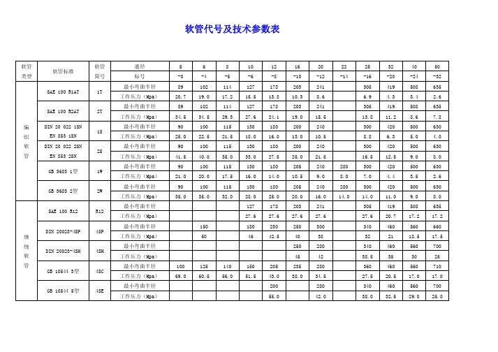
软管总成表示法 软管总成的订货代号按下述方法表示:
订货示例:20517-22 / 15217-06 X 1002-06SS X 1000 + RS; 当两端接头一样时,可省略右端接头代号。无弹簧护套则不写“+RS”。
EN10025-6
- 220 -
成品分析样品制备要符合 EN10025-1 的要求。 9.2 机械性能试验样品和试样的位置和方向 9.2.1 概述
此外进行冲击性能的检验,除非另外同意(见 7.3.2.2 和 7.3.2.3)纵向试样如: ——Q 在-20℃; ——QL 在-50℃; ——QL1 在-60℃。 7.3.2.2 要求另外的温度(表 6 和 7 中给出)应被同意。 见任选项 3。 7.3.2.3 如果在询问时同意和定制像在表 7 中给出的横向冲击功将用来替换纵向值。 见任选项 30。 7.3.3 厚度方向性能
——Si ≤ 0.030%,增加 CEV(碳当量)0.02%; ——Si ≤ 0.25%,增加 CEV(碳当量)0.01%。 7.3 机械性能
- 217 -
7.3.1 概述 7.3.1.1 按条款 8、9 和 10 中规定的检验和试验条件及 6.3 中规定的交货条件,机械性能要符合 表 5、表 6、表 7 中给出的值。 7.3.1.2 本标准中指定的的产品要采用公称厚度。 7.3.2 冲击性能 7.3.2.1 将按 EN 10025-1 进行冲击能值检验。
结构钢热轧产品 第 6 部分:
调质高屈服强度结构钢扁平材交货技术条件
BS EN 10025-6:2004
BS EN 10025-6:2004 与 BS EN 10025-1:2004 取代 BS EN 10137-1:1996,BS EN 10137-2:1996
本标准其它部分为: 第 1 部分:总交货技术条件 第 2 部分:焊接用热轧细晶粒结构钢–第 2 部分:正火/正火轧制钢材交货条件 第 3 部分:正火/正火轧制可焊接的细晶结构钢的技术交货条件 第 4 部分:热机械轧制焊接用细晶粒结构钢交货技术条件 第 5 部分:改进型耐大气腐蚀结构钢交货技术条件 1 范围 该标准第 6 部分,第 1 部分除外,规定了高屈服度特种钢扁平材的技术要求。钢种和质量及 品质在表 2~表 4 中给出(化学成分)和表 5~表 7(机械特性)和 6.3 中给出的调质条件的供给。 本标准中指定的钢可用于钢种 S460、S500、S550、S620 和 S690 的最小公称厚度为 3mm, 最大公称厚度≤150mm 的热轧板生产,淬火和回火后的钢指定的最小屈服强度是 460MPa1)到 960 MPa1) 2 标准参考标准 下列参考标准是该标准用途所必须的。关于过时的参考标准,只用于版本引用的用途。关于 更新的参考标准,采用最新的参考标准版本(包括任何修订)。 2.1 基础标准 EN 1011-2 焊接 – 金属材料焊接的建议 – 第 2 部分:铁素体钢电弧焊接的建议 EN 10020:2000 钢种的定义和分类 EN 10025-1:2004 结构钢热轧产品 – 第 1 部分:总交货技术条件 EN 10027-1 钢的命名体系–第 1 部分:钢名称、符号 EN 10027-2 钢的命名体系–第 2 部分:钢号 EN 10163-1 热轧钢板、宽扁平材和型钢表面条件的交货要求 – 第 1 部分:总要求。 EN 10163-2 热轧钢板、宽扁平材和型钢表面条件的交货要求 – 第 2 部分:板材和宽扁平 材 EN 10164 厚度方向性能钢产品–交货技术条件 CR 10260 钢产品名称体系–增加的符号 2.2 尺寸和公差标准(见 7.7.1)
化工泵选材手册

目录一,序。
2 二,常用金属材料表。
3 三,常用非金属辅助材料抗腐蚀性能表。
4 四,金属腐蚀数据对照表索引。
5 五,金属腐蚀数据对照表。
6 六,各种塑料橡胶介绍。
55 七,非金属腐蚀数据对照表索引。
57 八,非金属腐蚀数据对照表。
59 九,参考书目。
86序为了方便化工泵针对各种介质的选材,特别根据腐蚀数据与选材手册等腐蚀数据资料编写了这本化工泵选材手册。
由于他以介质与材料相互对应的表格形式列出腐蚀数据,可以使读者一目了然的根据各种不同介质选材。
在金属腐蚀数据表格前面我还列出了一些常规的选材方式,常用材料选用表格,和一些特别的腐蚀数据及其选材方法(粗略选材用)。
由于各种不同塑料橡胶耐腐蚀的差别明显,而且能承受的温度跨度太大。
所以在前面腐蚀数据对照表中我并未编写,而是先将常用的辅助塑料橡胶以表格(粗略选材用)的形式在前面列出。
其后以文字的形式对各种塑料橡胶进行了阐述,最后以另一种形式做出了非金属腐蚀数据表格。
当然这只是一本为方便而编写的手册,所以其中会舍弃许多腐蚀数据,所以仅能作为参考,查阅需核实后再选择。
如果查阅不到请查其他相关手册或者直接与本人联系。
由于时间仓促,本人经验有限,所以书中难免会有漏洞与错误,欢迎指正修改。
杨飞力2006.2.22常用金属材料应用表(表1)常用非金属辅助材料耐腐蚀性能表(表2)金属腐蚀数据对照表索引(首先为数字,其它按字母顺序)数字。
6-6 A.。
6-7 B.。
7-10 C.。
10-12 D.。
12-14 E.。
14-16 F.。
16-17 G.。
18-20 H.。
20-21 J.。
21-23 K.。
23-23 L.。
23-34 M.。
34-34 N.。
34-35 O.。
35-35 P.。
35-36 Q.。
36-39 R.。
39-40 S.。
40-44 T.。
44-45 W.。
45-46 X.。
46-50 Y.。
50-54 Z.。
54-55注:⑴、大写字母表示各种材料,A=碳钢和铸铁,B=高硅铸铁,C=高镍铸铁,D=铬13不锈钢,E=铬17不锈钢,F=铬18镍9不锈钢,G=铬18镍12钼不锈钢,H=铬20镍22~30不锈钢(20号合金),I=铝及铝合金,J=铜及青铜,K=黄注:⑴、大写字母表示各种材料,A=碳钢和铸铁,B=高硅铸铁,C=高镍铸铁,D=铬13不锈钢,E=铬17不锈钢,F=铬18镍9不锈钢,G=铬18镍12钼不锈钢,H=铬20镍22~30不锈钢(20号合金),I=铝及铝合金,J=铜及青铜,K=黄铬18镍9不锈钢,G=铬18镍12钼不锈钢,H=铬20镍22~30不锈钢(20号合金),I=铝及铝合金,J=铜及青铜,K=黄注:⑴、大写字母表示各种材料,A=碳钢和铸铁,B=高硅铸铁,C=高镍铸铁,D=铬13不锈钢,E=铬17不锈钢,F=铬18镍9不锈钢,G=铬18镍12钼不锈钢,H=铬20镍22~30不锈钢(20号合金),I=铝及铝合金,J=铜及青铜,K=黄注:⑴、大写字母表示各种材料,A=碳钢和铸铁,B=高硅铸铁,C=高镍铸铁,D=铬13不锈钢,E=铬17不锈钢,F=铬18镍9不锈钢,G=铬18镍12钼不锈钢,H=铬20镍22~30不锈钢(20号合金),I=铝及铝合金,J=铜及青铜,K=黄注:⑴、大写字母表示各种材料,A=碳钢和铸铁,B=高硅铸铁,C=高镍铸铁,D=铬13不锈钢,E=铬17不锈钢,F=铬18镍9不锈钢,G=铬18镍12钼不锈钢,H=铬20镍22~30不锈钢(20号合金),I=铝及铝合金,J=铜及青铜,K=黄注:⑴、大写字母表示各种材料,A=碳钢和铸铁,B=高硅铸铁,C=高镍铸铁,D=铬13不锈钢,E=铬17不锈钢,F=铬18镍9不锈钢,G=铬18镍12钼不锈钢,H=铬20镍22~30不锈钢(20号合金),I=铝及铝合金,J=铜及青铜,K=黄注:⑴、大写字母表示各种材料,A=碳钢和铸铁,B=高硅铸铁,C=高镍铸铁,D=铬13不锈钢,E=铬17不锈钢,F=铬18镍9不锈钢,G=铬18镍12钼不锈钢,H=铬20镍22~30不锈钢(20号合金),I=铝及铝合金,J=铜及青铜,K=黄铬18镍9不锈钢,G=铬18镍12钼不锈钢,H=铬20镍22~30不锈钢(20号合金),I=铝及铝合金,J=铜及青铜,K=黄注:⑴、大写字母表示各种材料,A=碳钢和铸铁,B=高硅铸铁,C=高镍铸铁,D=铬13不锈钢,E=铬17不锈钢,F=铬18镍9不锈钢,G=铬18镍12钼不锈钢,H=铬20镍22~30不锈钢(20号合金),I=铝及铝合金,J=铜及青铜,K=黄注:⑴、大写字母表示各种材料,A=碳钢和铸铁,B=高硅铸铁,C=高镍铸铁,D=铬13不锈钢,E=铬17不锈钢,F=铬18镍9不锈钢,G=铬18镍12钼不锈钢,H=铬20镍22~30不锈钢(20号合金),I=铝及铝合金,J=铜及青铜,K=黄铬18镍9不锈钢,G=铬18镍12钼不锈钢,H=铬20镍22~30不锈钢(20号合金),I=铝及铝合金,J=铜及青铜,K=黄铬18镍9不锈钢,G=铬18镍12钼不锈钢,H=铬20镍22~30不锈钢(20号合金),I=铝及铝合金,J=铜及青铜,K=黄注:⑴、大写字母表示各种材料,A=碳钢和铸铁,B=高硅铸铁,C=高镍铸铁,D=铬13不锈钢,E=铬17不锈钢,F=铬18镍9不锈钢,G=铬18镍12钼不锈钢,H=铬20镍22~30不锈钢(20号合金),I=铝及铝合金,J=铜及青铜,K=黄注:⑴、大写字母表示各种材料,A=碳钢和铸铁,B=高硅铸铁,C=高镍铸铁,D=铬13不锈钢,E=铬17不锈钢,F=铬18镍9不锈钢,G=铬18镍12钼不锈钢,H=铬20镍22~30不锈钢(20号合金),I=铝及铝合金,J=铜及青铜,K=黄注:⑴、大写字母表示各种材料,A=碳钢和铸铁,B=高硅铸铁,C=高镍铸铁,D=铬13不锈钢,E=铬17不锈钢,F=铬18镍9不锈钢,G=铬18镍12钼不锈钢,H=铬20镍22~30不锈钢(20号合金),I=铝及铝合金,J=铜及青铜,K=黄注:⑴、大写字母表示各种材料,A=碳钢和铸铁,B=高硅铸铁,C=高镍铸铁,D=铬13不锈钢,E=铬17不锈钢,F=铬18镍9不锈钢,G=铬18镍12钼不锈钢,H=铬20镍22~30不锈钢(20号合金),I=铝及铝合金,J=铜及青铜,K=黄注:⑴、大写字母表示各种材料,A=碳钢和铸铁,B=高硅铸铁,C=高镍铸铁,D=铬13不锈钢,E=铬17不锈钢,F=铬18镍9不锈钢,G=铬18镍12钼不锈钢,H=铬20镍22~30不锈钢(20号合金),I=铝及铝合金,J=铜及青铜,K=黄注:⑴、大写字母表示各种材料,A=碳钢和铸铁,B=高硅铸铁,C=高镍铸铁,D=铬13不锈钢,E=铬17不锈钢,F=铬18镍9不锈钢,G=铬18镍12钼不锈钢,H=铬20镍22~30不锈钢(20号合金),I=铝及铝合金,J=铜及青铜,K=黄注:⑴、大写字母表示各种材料,A=碳钢和铸铁,B=高硅铸铁,C=高镍铸铁,D=铬13不锈钢,E=铬17不锈钢,F=铬18镍9不锈钢,G=铬18镍12钼不锈钢,H=铬20镍22~30不锈钢(20号合金),I=铝及铝合金,J=铜及青铜,K=黄注:⑴、大写字母表示各种材料,A=碳钢和铸铁,B=高硅铸铁,C=高镍铸铁,D=铬13不锈钢,E=铬17不锈钢,F=铬18镍9不锈钢,G=铬18镍12钼不锈钢,H=铬20镍22~30不锈钢(20号合金),I=铝及铝合金,J=铜及青铜,K=黄注:⑴、大写字母表示各种材料,A=碳钢和铸铁,B=高硅铸铁,C=高镍铸铁,D=铬13不锈钢,E=铬17不锈钢,F=铬18镍9不锈钢,G=铬18镍12钼不锈钢,H=铬20镍22~30不锈钢(20号合金),I=铝及铝合金,J=铜及青铜,K=黄铬18镍9不锈钢,G=铬18镍12钼不锈钢,H=铬20镍22~30不锈钢(20号合金),I=铝及铝合金,J=铜及青铜,K=黄注:⑴、大写字母表示各种材料,A=碳钢和铸铁,B=高硅铸铁,C=高镍铸铁,D=铬13不锈钢,E=铬17不锈钢,F=铬18镍9不锈钢,G=铬18镍12钼不锈钢,H=铬20镍22~30不锈钢(20号合金),I=铝及铝合金,J=铜及青铜,K=黄铬18镍9不锈钢,G=铬18镍12钼不锈钢,H=铬20镍22~30不锈钢(20号合金),I=铝及铝合金,J=铜及青铜,K=黄注:⑴、大写字母表示各种材料,A=碳钢和铸铁,B=高硅铸铁,C=高镍铸铁,D=铬13不锈钢,E=铬17不锈钢,F=铬18镍9不锈钢,G=铬18镍12钼不锈钢,H=铬20镍22~30不锈钢(20号合金),I=铝及铝合金,J=铜及青铜,K=黄注:⑴、大写字母表示各种材料,A=碳钢和铸铁,B=高硅铸铁,C=高镍铸铁,D=铬13不锈钢,E=铬17不锈钢,F=铬18镍9不锈钢,G=铬18镍12钼不锈钢,H=铬20镍22~30不锈钢(20号合金),I=铝及铝合金,J=铜及青铜,K=黄铬18镍9不锈钢,G=铬18镍12钼不锈钢,H=铬20镍22~30不锈钢(20号合金),I=铝及铝合金,J=铜及青铜,K=黄注:⑴、大写字母表示各种材料,A=碳钢和铸铁,B=高硅铸铁,C=高镍铸铁,D=铬13不锈钢,E=铬17不锈钢,F=铬18镍9不锈钢,G=铬18镍12钼不锈钢,H=铬20镍22~30不锈钢(20号合金),I=铝及铝合金,J=铜及青铜,K=黄注:⑴、大写字母表示各种材料,A=碳钢和铸铁,B=高硅铸铁,C=高镍铸铁,D=铬13不锈钢,E=铬17不锈钢,F=铬18镍9不锈钢,G=铬18镍12钼不锈钢,H=铬20镍22~30不锈钢(20号合金),I=铝及铝合金,J=铜及青铜,K=黄注:⑴、大写字母表示各种材料,A=碳钢和铸铁,B=高硅铸铁,C=高镍铸铁,D=铬13不锈钢,E=铬17不锈钢,F=铬18镍9不锈钢,G=铬18镍12钼不锈钢,H=铬20镍22~30不锈钢(20号合金),I=铝及铝合金,J=铜及青铜,K=黄铬18镍9不锈钢,G=铬18镍12钼不锈钢,H=铬20镍22~30不锈钢(20号合金),I=铝及铝合金,J=铜及青铜,K=黄注:⑴、大写字母表示各种材料,A=碳钢和铸铁,B=高硅铸铁,C=高镍铸铁,D=铬13不锈钢,E=铬17不锈钢,F=铬18镍9不锈钢,G=铬18镍12钼不锈钢,H=铬20镍22~30不锈钢(20号合金),I=铝及铝合金,J=铜及青铜,K=黄铬18镍9不锈钢,G=铬18镍12钼不锈钢,H=铬20镍22~30不锈钢(20号合金),I=铝及铝合金,J=铜及青铜,K=黄注:⑴、大写字母表示各种材料,A=碳钢和铸铁,B=高硅铸铁,C=高镍铸铁,D=铬13不锈钢,E=铬17不锈钢,F=铬18镍9不锈钢,G=铬18镍12钼不锈钢,H=铬20镍22~30不锈钢(20号合金),I=铝及铝合金,J=铜及青铜,K=黄注:⑴、大写字母表示各种材料,A=碳钢和铸铁,B=高硅铸铁,C=高镍铸铁,D=铬13不锈钢,E=铬17不锈钢,F=铬18镍9不锈钢,G=铬18镍12钼不锈钢,H=铬20镍22~30不锈钢(20号合金),I=铝及铝合金,J=铜及青铜,K=黄注:⑴、大写字母表示各种材料,A=碳钢和铸铁,B=高硅铸铁,C=高镍铸铁,D=铬13不锈钢,E=铬17不锈钢,F=铬18镍9不锈钢,G=铬18镍12钼不锈钢,H=铬20镍22~30不锈钢(20号合金),I=铝及铝合金,J=铜及青铜,K=黄铬18镍9不锈钢,G=铬18镍12钼不锈钢,H=铬20镍22~30不锈钢(20号合金),I=铝及铝合金,J=铜及青铜,K=黄铬18镍9不锈钢,G=铬18镍12钼不锈钢,H=铬20镍22~30不锈钢(20号合金),I=铝及铝合金,J=铜及青铜,K=黄铬18镍9不锈钢,G=铬18镍12钼不锈钢,H=铬20镍22~30不锈钢(20号合金),I=铝及铝合金,J=铜及青铜,K=黄注:⑴、大写字母表示各种材料,A=碳钢和铸铁,B=高硅铸铁,C=高镍铸铁,D=铬13不锈钢,E=铬17不锈钢,F=铬18镍9不锈钢,G=铬18镍12钼不锈钢,H=铬20镍22~30不锈钢(20号合金),I=铝及铝合金,J=铜及青铜,K=黄注:⑴、大写字母表示各种材料,A=碳钢和铸铁,B=高硅铸铁,C=高镍铸铁,D=铬13不锈钢,E=铬17不锈钢,F=铬18镍9不锈钢,G=铬18镍12钼不锈钢,H=铬20镍22~30不锈钢(20号合金),I=铝及铝合金,J=铜及青铜,K=黄注:⑴、大写字母表示各种材料,A=碳钢和铸铁,B=高硅铸铁,C=高镍铸铁,D=铬13不锈钢,E=铬17不锈钢,F=铬18镍9不锈钢,G=铬18镍12钼不锈钢,H=铬20镍22~30不锈钢(20号合金),I=铝及铝合金,J=铜及青铜,K=黄铬18镍9不锈钢,G=铬18镍12钼不锈钢,H=铬20镍22~30不锈钢(20号合金),I=铝及铝合金,J=铜及青铜,K=黄注:⑴、大写字母表示各种材料,A=碳钢和铸铁,B=高硅铸铁,C=高镍铸铁,D=铬13不锈钢,E=铬17不锈钢,F=铬18镍9不锈钢,G=铬18镍12钼不锈钢,H=铬20镍22~30不锈钢(20号合金),I=铝及铝合金,J=铜及青铜,K=黄。
GBU1006中文资料
DS30052 Rev. D-2
1 of 2
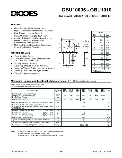
GBU10005 - GBU1010
元器件交易网
10
I(AV), AVG FWD OUTPUT CURRENT (A)
8
IF, INSTANTANEOUS FWD CURRENT (A)
Resistive or Inductive Load
元器件交易网
GBU10005 - GBU1010
10A GLASS PASSIVATED BRIDGE RECTIFIER Features
· · · · · · · Glass Passivated Die Construction High Case Dielectric Strength of 1500VRMS Low Reverse Leakage Current Surge Overload Rating to 220A Peak Ideal for Printed Circuit Board Applications Plastic Material: UL Flammability Classification Rating 94V-0 UL Listed Under Recognized Component Index, File Number E94661
J
-
~ ~ +
D E F G P N
H J K L M N P
3.2 X 45°
H
All Dimensions in mm
Maximum Ratings and Electrical Characteristics
Single phase, 60Hz, resistive or inductive load. For capacitive load, derate current by 20%. Characteristic Peak Repetitive Reverse Voltage Working Peak Reverse Voltage DC Blocking Voltage RMS Reverse Voltage Average Rectified Output Current (Note 1) @ TC = 100°C Non-Repetitive Peak Forward Surge Current 8.3ms single half sine-wave superimposed on rated load (JEDEC Method) Forward Voltage (per element) @ IF = 5.0A Peak Reverse Current at Rated DC Blocking Voltage I2t Rating for Fusing (Note 2) Typical Junction Capacitance per Element (Note 3) Typical Thermal Resistance Junction to Case (Note 1) Operating and Storage Temperature Range @ TC = 25°C @ TC = 125°C Symbol VRRM VRWM VR VR(RMS) IO IFSM VFM IR I2t CJ RqJC Tj, TSTG GBU 10005 50 35
滚动轴承国家标准目录

一、滚动轴承国家标准目录
欢迎共阅
欢迎共阅
欢迎共阅
欢迎共阅
欢迎共阅
欢迎共阅
欢迎共阅
二、滚动轴承机械行业标准目录
欢迎共阅
欢迎共阅
欢迎共阅
欢迎共阅
欢迎共阅
欢迎共阅
三、全国滚动轴承标准化技术委员会技术文件目录
欢迎共阅
欢迎共阅
欢迎共阅
注:ZXB为中国轴承协会标准代号;SAC TC98与CSBTS TC98同为全国滚动轴承标准化技术委员会技术文件代号。
欢迎共阅
四、轴承工业国际标准及我国采标情况一览表
欢迎共阅
欢迎共阅
欢迎共阅
欢迎共阅
欢迎共阅
欢迎共阅。