捷控高清混插矩阵说明书
HDMI 4x2 矩阵开关器 用户手册说明书

HDMI® 4x2 Matrix Switcher with Dual Audio De-embedder, ARC & 4K UltraHDUser Manual v1.1All rights reserved 20151.IntroductionThis is a high performance HDMI Matrix with four HDMI inputs & two outputs, it allows any source (Blue-Ray player, HD DVD player, satellite receiver, game system, etc.) to be shown on the any of the two displays simultaneously, and supports 4K×2K, 3D, 12-bit Deep Color. With its 3Gbps bandwidth and the additional features of the latest HDMI standards you can be sure of great HDMI distribution. It support dual ARC and wide band IR extend function also.2.FeatureCompliant with HDMI 1.4,HDCP 1.4Supports multiplexed HDMI 4-input and 2-outputSupports video format up to 4k2k@30Hz with 24bit RGB/YCbCr 4:4:4/YCBCR 4:2:2, and up to 4k2k@60Hz with 12bit YCBCR 4:2:0.Deep Color support 48/36/30/24-bitSupports reception of any audio data conforming to the HDMI specification such PCM at up to 192kHz, compressed audio (IEC 61937), DSD, DST, DTS and HBR.Supports Dual ARC controlSuper wideband IR control system, IR transport channel can be forward or backward. Supports button,IR,RS232 etc various controlled ways;3.Package Contents4x2 HDMI Matrix 1pc5V/1A DC power adaptor 1pcRemote Control 1pcOperation Manual 1pcWideband IR Tx 4pcWideband IR Rx 2pcRS232 Cable 1pc4.SpecificationVideo Bandwidth297MHz/2.97 GbpsInput Ports 4 × HDMI (Female type)Output Ports 2 × HDMI (Female type)Output Resolution480i ~1080p50/60, 4Kx2K@24/30, VGA~UXGAHDMI Cable in1080p/12bits (15m)HDMI Cable out1080p/12bits (15m)ESD Protection±8 kV (air-gap discharge)Human Body model: ±4 kV (contact discharge)Power Supply 5 V/1A DC (US/EU standards, CE/FCC/UL certified) Dimensions113 mm (W) × 260 mm (D) × 26 mm (H)Weight750 gChassis Material MetalSilkscreen Color BlackOperating Temperature0 °C~40 °C/ 32 °F~104 °FStorage Temperature−20 °C ~ 60 °C/−4 °F ~140 °FRelative Humidity20~90 % RH (non-condensing)Power Consumption 2.0 W5.Operation and Functions5.1 Front panel1.ON/OFF: Power on/off switch.2.POWER LED: This red LED illuminates when the device is connected with powersupply.3.IR: Remote control receiver window.4.OUT A: These red LED illuminates when the output A channel select to thecorresponding input.5.OUT B: These red LED illuminates when the output B channel select to thecorresponding input.6.ARC: Press this button to select OUT A or OUT B Coaxial audio from source or HDTV. ARC function: If you need use ARC, your HDTV must support this function, when you open the ARC function, the Coaxial of the matrix will output the HDTV current display content audio. Otherwise will output the matrix input source audio.7.RST BUTTON: Press this button the matrix setting will recover to factory state.5.2 Rear panel1.RS232: Connect the RS232 port to the PC or notebook by RS232 Cable to control thematrix.2.Input:This slot is where you connect the HDMI source output from Blu-ray, PS4,Set-top Box or a laptop.3.IR TX: Connect the IR Blaster cable included in the package for IR signal transmission.Pace the IR blaster in direct line-of-sight of the equipment to be controlled.4.IR RX: Connect to the IR Receiver for IR signal reception. Ensure that remote beingused is within the direct line-of-sight of the IR receiver.5.OUT B:The HDMI is where you connect the HDTV or monitor with HDMI cable forinput source display. The Coaxial audio output is where you connect to the amplifier with coaxial cable.6.OUT A:The HDMI is where you connect the HDTV or monitor with HDMI cable forinput source display. The Coaxial audio output is where you connect to the amplifier with coaxial cable.7.DC 5V: Plug the 5V1A DC power supply into the unit and connect the adaptor to ACwall outlet.5.3 Connect and Operate1. Connect the signal sources such as Blu-Ray Players, Play Station 3, audio/video receiver, satellite receivers and computers equipped with HDMI output interfaces with a short high-speed HDMI cable to the HDMI Matrix inputs.2. Connect the HDMI output from the HDMI Matrix to a high-definition display device such as HDTV, 4K Ultra HDTV or projectors with HDMI input interfaces. Use high-speed HDMI cables that are recommended for the distances that are required for each connection.3. The Matrix is powered by an external power supply that is included. Connect power first to the source, then to the Matrix and then to each HD TV or projector.4. The input source can be controlled from the display. This is accomplished by using an optional IR Receiver pigtail pointing away from the display(s), which can be connected with the optional HDMI IR Adapter, and inserted between the HDMI cable connector and the display with the toggle switcher at the “IR” posit ion. The IR Transmitter pigtail is then connected to the Matrix and pointed to the source(s). A remote control is used at the display to select switch inputs and output. The matrix also has the capability of being controlled via Remote control.5.4 Wideband IR (30 KHz---60 KHz) introductionIR BLASTER (TX)To control the source:Plug IR Blaster into IR TX port of transmitter unit; place blaster in front of the IR eye of the source.IR RECEIVER (RX)To control the source:Plug IR Receiver into IR RX port of receiver unit; place receiver at or near display.6.Remote ControlOUTPUT A: Press IN1\IN2\IN3\IN4 button will fast switch to selectinput source to HDMI OUTPUT A, and the LED will indicate thecorresponding input source. Press button OUTPUT A will cyclefrom input IN1\IN2\IN3\IN4.OUTPUT B: Press IN1\IN2\IN3\IN4 button will fast switch to selectinput source to HDMI OUTPUT B, and the LED will indicate thecorresponding input source. Press button OUTPUT B will cyclefrom input IN1\IN2\IN3\IN4.7. RS-232 Control guide using a PCInstallationThe PC controller is green software. Just use a cable to connect the PC via RS232 port and copy “4x2 HDMI matrix Controller.exe” to PC to complete installation.Preparation1. Connect PC and multi-viewer by RS232 cable2. Power-up multi-viewer3. Double click 4x2 HDMI matrix Controller.exe icon to run itGeneral Page1.Select RS232 COM port2.Click to connect or disconnect PC and Matrix3.Click to refresh device status: include device information and Input/Output Settings on“Matrix” page4.Click to clear device information5.Click to reset to the factory settingsEDID PageThe controller has 3 methods to set the EDID mode. Manual mode, Copy mode and open EDID file mode.1.Select the needed EDID to input port and click set button the EDID will write to theselected HDMI input ports.2.Copy the selected HDMI output or HDBT output EDID and click set button to write tothe selected HDMI input ports.3.Open the user define EDID file and click set button to write to the selected HDMI inputports.4.Click the status button to refresh input EDID status.Matrix Page1.LED which display Input number for respective Output2.Click to select Input port for respective Output port3.Click to select previous or next Input port for respective Output port4.Click to open or close output ARC functionFirmware Upgrade Page1.Click to open FW file (file extension is “.fw”)2.Click to upgrade the Matrix software3.Display the message of the software upgrade process.8.Connection DiagramWarrantyB.KanexPro TM warrants that (a) its products (the “Product”) will perform greatly inagreement with the accompanying written materials for a period of 3 years from the date of receipt and (b) that the product will be free from defects in materials and workmanship under normal use and service for a period of 1 year.C.Customer RemediesKanexPro entire liability and Customer’s exclusive remedy shall be, at KanexPro option, either return of the price paid for the product, or repair or replacement of the Product that does not meet this Limited Warranty and which is returned to Kanex Pro with a copy of customers’ receipt. This Limited Warranty is void if failure of the Product has resulted from accident, abuse, or misapplication. Any replacement Product will be warranted for the remainder of the original warranty period or 90 days whichever is longer.D.NO LIABILITY FOR DAMAGESTo the maximum extent permitted by applicable law, kanex Pro disclaims all other warranties, either express or implied, including, but not limited to implied warranties of merchantability and fitness for a particular purpose, with regard to product and any related written materials. This limited warranty gives customers specific legal rights. Customers may have other rights depending on the jurisdiction.E.NO LIABILITY FOR DAMAGESTo the maximum extent permitted by applicable law, in no event shall Kanex Pro be liable for any damages whatsoever (Including without limitation, special, incidental, consequential, or indirect damages for personal injury, loss of business profits, business interruption, loss of business information, or any other pecuniary loss) arising out of the use of or inability to use this product, even if Kanex pro has been advised of the possibility of such damages.SupportKanexPro Technical and Customer support inquiries can be sent electronically via the following avenues:Tech Support Inquiry: /support/Email: ********************KanexPro Customer support can be reached via phone at (888) 975-1368 (International Calls: 1-714-332-1682) during the following times:Monday – Friday: 6:00 am – 5:00 pm PST。
HDMI矩阵说明书
HDMI矩阵操作手册安全操作指南为确保设备可靠使用及人员的安全,在安装,使用和维修时,请遵守以下事项:1.系统接地。
系统必须有完善的接地,否则,不仅造成讯号干扰,不稳定或机械损坏,而且还可能因漏电引起人身事故;请使用标准的三线电源插座,其地线接地电阻应小于1Ω。
2.禁止改变原设计。
禁止对本产品的机械和电器设计更改或增添任何部件。
否则。
本公司对由此所带来的后果不负责任。
3.请勿使用两芯插头,确保设备的输入电源为220V50Hz的交流电。
4.机器内有220V高压部件,请勿打开机壳,以免触电。
5.不要将机器置于过冷或过热的地方。
6.设备电源在工作时会发热,因此要确保工作环境的良好通风。
以免温度过高而损坏机器。
7.阴雨潮湿天气或长时间不用时,应关闭设备电源总闸。
一、产品简介…………………………………………..……………….1.关于HDMI系列矩阵切换器………..…….2.HDMI矩阵连接示意图………………二、矩阵系统的安装………..…………………….1、矩阵与控制电脑的连接……………………………….……….三、前面板功能键…………………………..………………..……….1、切换指令……………………………………..…………….2、UP、Down状态查询指令……………………..………….3、SAVE存储指令…………………………………………….4、RECALL调用指令…………………………………...…….5、CANCEL键…………………………………………..…….四、矩阵控制软件…………………….……….….五、R S232通讯协议…………………………………………………产品简介:1.1关于HDMI系列矩阵切换器HDMI数字视频矩阵切换器是为了将计算机数字视频信号进行重新分配和组合的矩阵交换设备,该设备可将多路HDMI数字视频输入信号切换到多路输出通道的任意通道上去。
可广泛用于所有需要进行HDMI信号分配和组合的场合,应用领域涉及军工、多媒体教学、电视电话会议、金融、科研、气象等领域。
高清无缝混合矩阵(加强型)带拼接讲义
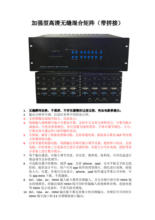
加强型高清无缝混合矩阵(带拼接)1.无缝瞬间切换,不黑屏,不存在缓慢的过度过程,快如电影换镜头;2.输出分辨率可调,以适应多种不同的显示屏;3.支持图像局部细节放大、局部显示;4.每路输入视频都可独立可叠加字幕,支持中文及英文两种语言;字幕可静止或滚动,可更改背景颜色,也可设置为透明背景,字体可调节颜色、大小,字幕内容可通过串口软件随时更改;5.可拼接,兼容了拼接处理器功能,支持普通电视、液晶显示器及DLP等实现大屏幕拼接功能;6.自带音量控制器功能,每路输出音频可独立调节音量,提供串口协议,支持电脑、中控等第三方设备对它进行音量控制,音量大小可在电视、投影等显示设备上进行数字提示;7.每个输出通道,可独立调节亮度、对比度、饱和度、锐利度,可对色温进行增益调节及补偿调节;8.可选配内置中控模块,提供app,支持iphone、ipad、安卓平板及手机无线控制,提供设计平台,用户可对app软件的背景图片、颜色进行更换,按钮的大小、位置、外观可自由设计;iphone、ipad软件通过苹果公司审核,可从app store下载,不需越狱;9.DVI、VGA、AV、HDMI输入板卡都带音频输入,并且音频可溶合到HDMI输出的视频里,即输出端的HDMI线可同时传输输入的视频和音频,连接电视等HDMI显示设备时,不需另接音频线;10.DVI、VGA、AV、HDMI输出板卡都支持独立的音频输出,音频信号可同时在HDMI数字接口和3.5音频模拟接口输出;11.HDMI及DVI输入端带数字均衡调整电路,输出带信号预加重增强电路,使信号能进行更长距离传输,输入输出都可超过20米距离;12.插卡式结构设计,采用每张卡4个通道的设计,可灵活配置输入输出信号类型及信号通道数,扩展方便,维护便捷,主机可以同时兼容不同的信号,可以配置AV、VGA、YPbPr、DVI、HDMI、HD-SDI、光纤、网络等不同的输入输出板卡,互不干扰,同时传输;13.所有板卡和主板,采用德国Erni原装进口专业高速连接器,非普通金手指连接;14.支持RS-232、红外(选配)、网口(选配)控制信号切换功能;15.一体化全铝拉丝面板、蓝光液晶显示屏,美观高档的外观设计;16.采用Contrex嵌入式ARM处理器控制,运行速度更快,系统更稳定;17.支持一键快速查询功能,方便察看矩阵的切换状态;18.具有掉电记忆功能带有断电现场保护,上电自动恢复关机前状态;19.标准机架安装的金属机箱。
HD44CC5高清视频矩阵开关说明书

INSTALLATION INSTRUCTIONSHD44CC5 HD44CHigh Definition Video Matrix Switcher,Coaxial and CAT5 High Definition Video Matrix Switcher,Coaxial OnlyDESCRIPTIONThe HD44CC5 four-source, four-zone high-definition matrix switcher has component video andS/PDIF digital audio inputs for each source. All four zone outputs have component video output and S/PDIF audio output for economical local distribution up to 250’, as well as a RJ45 output for transmission of the video and digital audio signal up to 1000’ to the HDRXSG01 receiver located in the zone. Both coaxial component video output and CAT5 output are active simultaneously, making it possible to distribute four sources to eight outputs at the same time.The HD44C has the same great features as the HD44CC5 without the CAT5 output. The HD44C is ideal for installations requiring local switching and distribution up to 250’.The HD44CC5 and HD44C unit is expandable up to 16 zones.SPECIFICATIONSSize: 17” W x 7 3/8” D x 3 15/16” HWeight: 9.25 lbs (4.2 kilos)Controllable through IR and RS232 commandsBandwidth supports resolutions of 1080p, 1080i, 720p, 480p and 480i.Optional Rack Mount kit available (RM2UKIT)Power supply (120VAC, 0.25A, 50-60Hz)Operates in temperatures up to 55 degrees Celsius.DETAIL OVERVIEW[1] SOURCE LOOP-THROUGH CONNECTIONThe source inputs are buffered to provide an output at the same levels, assuming a 75-ohm termination is on the output. Use these connections for HD44 expansion systems. The buffers are an active circuit. The HD44 must be powered on for an active connection.[2] SOURCE INPUTSGold-plated RCA jacks for connection from the output of the source. Color coordinated to match all HD source components.[3] IR RECEIVERThe rear panel IR receiver is a 3.5mm Stereo jack that is compatible with all Xantech IR receivers, such as the 291-10. Switch 4 must be in the OFF position to use this jack.PLUG CIRCUITSIGNALTIP IRRING GROUNDSLEEVE +12VDC, 25mA[4] IR BUS, EMITTER PORTThe 3.5mm Mono jack is an emitter port. The IR signal is connected to the IR Receiver. A Xantech 283M emitter can be connected to this port.PLUG 2-Pin WECO CIRCUITSIGNALTIP +IRSLEEVE - GROUNDThe 2-Pin WECO screw terminal is an IR port. The IR signal is connected to the IR Receiver. The WECO screw terminal allows easy installation to a typical Xantech IR connecting block.[5] RS232 (SERIAL) COMMANDSThe RS232 Port is bi-directional. The communication is set to 9600 Baud 8-N-1.DB9 CONNECTORCIRCUIT PINTX 2RX 3GND 5RS232 COMMAND STRUCTUREWhere:{CR#} – Carriage Return (0x0D){z#} - Zone Number. Range is 1..4 (1..16 if expanded){s#} - Source Input Number. Range is 1..4{0/1} – Either 0 (zero) or 1 (one). 0 – Off, 1 – On.NAME COMMAND RETURN REMARKS!{z#}PR01+ To turn on Zone 2: !2PR1+ or !02PR1+ or !2PR01+ or !02PR01+Zone Power!{z#}PR00+ OK{CR}ERROR{CR} To turn off Zone1: !1PR0+ or !01PR0+ or!1PR00+ or !01PR00+Zone Power Toggle !{z#}PT+OK{CR}ERROR{CR}All Zones Off !EO+ OK{CR}ERROR{CR}Turns all the zones off.All Zones On !EA+ OK{CR}ERROR{CR}Turns all the zones on.Zone Restore All !RF+ OK{CR}ERROR{CR}Restore all the Zone-to-Source routing to thecurrent selection: !RF+Input (Source) Select !{z#}SS{s#}+OK{CR}ERROR{CR}To set Zone 1 to Source Input 4: !1SS4+Ping Expansion Port !RP+OK{CR}ERROR{CR}Request that any unit connected to the expansionport respond with a ping.Return Ping to Xantech port !SP+ +Returns a +. Meant for inter-expansion boxcommunications.RS232 QUERIES Where:{CR#} – Carriage Return (0x0D){z#} - Zone Number. Range is 1..4 (1..16 if expanded){s#} - Source Input Number. Range is 1..4{0/1} – Either 0 (zero) or 1 (one). 0 – Off, 1 – On.NAME QUERY RETURN EXAMPLERETURNEXPLANATIONZone Power ?{z#}PR+?{z#}PR{0/1}+ ?4PR0+{CR} Power in zone 4 is OFF.Input Select ?{z#}SS+ ?{z#}SS{s#}+ ?4SS3+{CR} Zone 4 currently has source 3 selected.System Info ?SI+ SI{Device:HD44,Device Cde:000C,Hardware Cde:0000,Reserved Cde:0000,Firmware Ver:X.Y.Z}+SIDevice:HD44, DeviceCde:000C,Hardware Cde:0000,Reserved Cde:0000,Firmware Ver:1.1.0This command is used only with single unitsystems. Note this is command does nottrickle down to the expansion port.X = MajorY = MinorZ = Release[6] AC POWER INPUTStandard IEC 3-Conductor AC Line Cord Receptacle for plug-in of a 3-conducator power line cord. Be sure to note if the power receptacle is domestic (120VAC type) or international (240VAC type).[7] RS232 EXPANSIONThe HD44C and HD44CC5 can be expanded into a larger system. By using any combination of the HD44C and HD44CC5 (up to 4 units), a larger High-Definition distribution system can be created.For instance, two HD44C units can be combined to create a much larger 4 source input to 8 zone output. The two HD44C units must have their own unique address (see ADDRESS (DIP SWITCH) section). The top unit (master controller) must always be addressed as UNIT 1. See Section 8 for setting the unit address. The included RS232 expansion cable allows a single RS232 control port to be used to command the entire system. The expansion cable is connected between the DB9 (5) and 3.5mm stereo mini jack (7).IMPORTANT NOTICEThe top unit (master controller) must always be addressed as UNIT 1.PLUG3.5MMMALEDB9CIRCUIT PIN PLUG CIRCUITTXTX 2 TIPRX 3 RINGRXGND 5 SLEEVE GND[8] ADDRESS (DIP SWITCH)Switch 1 & 2: Unit Address (for Expansion mode)ADDR SW 1 SW 2UNIT 1 OFF OFFUNIT 2 OFF ONUNIT 3 ON OFFUNIT 4 ON ONSwitch 3: ON for firmware write protectSwitch 4: ON for front panel IR receiver / OFF for rear panel IR receiver[9] CAT5 ZONE OUTPUTOutput connection to the HDRXSG01 receiver module. Uses standard CAT5 cable. Be sure to verify CAT5 wiring connection is correct before installation.[10] COAXIAL ZONE OUTPUTGold-plated RCA jacks for connection to an HD monitor. Color coordinated to match all HD type products. The CAT5 and coaxial output can be used at the same time.IMPORTANT NOTICEAfter connecting the CAT5 cable to the receiver (HDRXSG01), thepower supply to the receiver should be unplugged for a few secondsand then reconnected. This allows the receiver to go through the fullprocess of line length and line quality self-calibration.Do not connect the power supply to the receiver until after the CAT5connection. The HD44CC5 must be powered on before theHDRXSG01.As an alternate process to this procedure, the power may be cycledoff for a few seconds and reapplied to accomplish the same full self-calibration process.If for some reason the system losses power at the receiving end(HDRXSG01), the transmitting end (HD44CC5), or both ends, the fullself-calibration process will automatically occur.QUICK INSTALLATION: HD44CC5 and HDRXSG01[1] Connect the High-Definition Source to the HD44CC5 or HDTXSG01. Figure 1 below shows a HD44CC5 (video matrix transmitter) connected to the HDRXSG01 (receiver).[2] Using CAT5 cable, connect the HD44CC5 zone output or the output from the HDTXSG01 to the HDRXSG01. Connect power to the HD44CC5 first. Then connect power to the HDRXSG01.[3] On the HD44CC5, set the source to zone to enable the HDRXSG01 from the connected High-Definition source. See HD44CC5 manual on how to use RS232 and IR RC68+ controls.[4] Installation Complete! No adjustments needed!RC68+ (IR) COMMANDSThe RC68+ should be set to Group Code “C0”.ZONE 1 ZONE 2 ZONE 3 ZONE 41 ZonePowerToggle 80 48 10 90SRC 1 SRC 2 SRC 3 SRC 4 Zone 1 Source Select 00 C0 50 D0Zone 2 Source Select 40 A0 30 B0 2Zone 3 Source Select 20 E0 70 F0Zone 4 Source Select 60 88 18 98ZONE 1 ZONE 2 ZONE 3 ZONE 43 ZoneOn 08 A8 38 B8 Power4 Zone Power Off 28 E8 78 F85 Zone Power All Off 686 Zone Restore All C87 Zone Power All On 58Note: For expanded systems, the ‘Primary’HD44 should remain on the default group codeof “C0” but each additional HD44 will need to bechanged to a different discrete Code Group sothe units can be individually controlled. Tochange the Group Code of the additional HD44’splease see the RC68X instruction manual(section labeled CHANGING THE INTERNALCODE GROUP NUMBER OF A XANTECHMODEL) or the Application Advisory AA-09 onthe Xantech Web Site[URL:/products/a_folder/a_aa09.pdfADVANCE INSTALLATIONFIGURE 2: Below shows a diagram for a sports bar application. With the equipment rack located near or behind the bar area, the coaxial outputs can be used for local HD monitors. The CAT5 outputs can be used to deliver HD content to areas such as outdoor patios and pool table recreational areas.FIGURE 2FIGURE 3: The figure in the next page shows an expanded HD44CC5 system. With two HD44CC5 devices, HD content can be distributed to 16 displays (8 with CAT5 outputs, 8 with coaxial outputs). The included RS232 expansion cable allows a single RS232 control port to be used to command the entire system.FIGURE 3 (Note: The top unit (master unit) must be addressed as UNIT #1)COMMON PROBLEMS AND TROUBLESHOOTINGPoor video quality (picture is washed out): Several manufacturers of cable and satellite box may have higher than normal DC offset on the video signals. When connected to an HD44C, HD44CC5, and HDTXSG01, this may result in a washed out picture. To remedy this problem, a DC blocker should be used between the source component and the HD44C, HD44CC5, and HDTXSG01. Picture appears to be blooming: A blooming picture is usually caused by a video signal that is too high. One reason for this problem is the HDRXSG01 was not synchronized to the HD44CC5. To correct this, be sure the CAT5 cables is connected between the HD44CC5 and HDRXSG01. Remove power from both devices. Simultaneously apply power to both units. This will synchronize the correct signal strength.Xantech Corporation13100 Telfair Avenue, 2/FSylmar, CA 91342Phone: (818) 362-0353, Fax: (818) 362-9506Installation Instructions, HD44CC5, HD44C © 2007 Xantech Corporation This document is copyright protected. No part of this manual may be copied or reproduced in any form without priorwritten consent from Xantech Corporation.Xantech Corporation shall not be liable for operational, technical, or editorial errors/omissions made in this document.Document Number 08905071BThis page intentionally left blankThis page intentionally left blankThis page intentionally left blank。
DSW-822矩阵用户手册 -高清

8x2数字高清切换器8x2数字高清切换器用户手册声明未经本公司书面许可,任何个人和单位不得摘抄或者复制本手册内容的部分或者全部,并不得以任何形式进行传播。
由于产品版本升级或其它原因,本手册内容会不定期更新,恕不另行通知。
本手册仅作为使用指导,本手册中的内容不构成任何明示或暗示的担保。
本手册所包含的商标都属各自所有人所有。
关于本手册1.本手册适用于8X2数字高清切换器DSW-822H、8X2混合高清切换器(DSW-822HM1、DSW-822HM2),并作为用户配置该系列产品的标准指导手册;2.更新日期2015/2/1目录安全操作指南 (4)第1章产品概述 (5)第2章接口说明 (7)2.1后面板接口说明 (7)2.2前面板指示说明 (9)第3章使用说明 (11)3.1 开箱检查 (11)3.2 使用前准备 (11)3.3 接入信号线 (11)3.4 检查设备运行状态 (12)3.5 其他功能的操作与说明 (12)3.6其他线方法 (13)第4章常见问题及排除 (15)附录一:DSW-1602/DSW-822串口切换命令协议 (16)安全操作指南为确保设备正常使用及人员的安全,在安装,使用和维护时,请仔细阅读并遵守以下事项:•系统必须在接地状态下工作。
否则,在工作中不仅对信号造成干扰、对设备本身也可能造成损坏,而且还容易漏电引起意外事故。
•禁止对本产品的机械和电器设计更改或增添任何部件。
否则生产厂家对由此所带来的危害性结果不负责任。
•请勿使用两芯插头,确保设备的输入电源为220V 50Hz的交流电。
•请勿将设备置于过冷、过热或过于潮湿的地方。
•设备在工作时会发热,因此请保持工作环境的良好通风性,以免温度过高而损坏机器。
•本产品严禁带电插拔输入信号线缆、输出信号线缆。
•在进行下列操作之前,必须将设备的电源线从交流供电电源拔下:•取下或重装设备的任何部件;•断开或重接设备的任何电器插头或其它连接。
•未经许可,请勿擅自拆开设备机箱进行维修等操作,设备内有220V交流高压部件,以免发生意外事故或加重设备的损坏程度。
Atlona 2x4 HDMI 矩阵切换器说明书

A tlonA2x4 HDMI Matrix SwitcherAT-HD-V24M1. Package Contents (1)2. Introduction (1)3. Features (1)4. Specifications (2)5. Panel Descriptions (2)5.1 Front Panel (2)5.2 Rear Panel (3)6. Remote Control (3)7. IR Extender (4)7.1 IR Extender Connection (4)7.2 The IR Extender Components Setup (4)8. RS-232 Serial Interface (5)8.1 RS-232 Serial Interface Connect a PCor Control System (5)8.2 RS-232 (5)8.3 Commands (5)9. RS-232 Serial Commands (6)9.1 Standby Mode (6)9.2 Power Off Mode (6)9.3 Front Panel Lock (6)9.4 Unit Reset (6)10. Tipical Application (7)11. Safety Information (8)12. Warranty (9)13. Atlona Product Registration (10)• 2x4 HDMI Matrix Switcher (AT-HD-V24M)• Instruction Manual• IR Remote Control• Universal AC/DC power adapter: 12VDC• 19 inch Ear mount pair• IR Extender receiver• RS232 package (RS232 DVD Drive & RS232 Cable)Atlona Technologies’ AT-HD-V24M is a 2x4 HDMI Matrix Switcher with audio designed to work as a switcher for multiple Audio/Video sources and displays. This Atlona unit is capable of switching HDMI signals between two sources and four displays. Because it is a matrix switch, any or all of the 2 inputs can simultaneously be switched to any or all of the outputs. This devise will support high definition video in multiple resolutions of up to 1080p or 1920x1200. This unit has quick and easy installation. With manual, RS232, as well as IR Remote control options, Atlona’s AT-HD-V24M Matrix Switcher is HDCP Compliant making it is perfect for all HDMI devices, PC monitors, Plasma TV displays and HDTVs.• Switches HDMI Video signal with Audio between 2 sources and 4 displays.• Matrix Switch: each input can be directed to any or all outputs at the same time• Quick and easy installation• HDMI digital video/audio format, DVI format and HDCP compliant• Supports link speeds of up to 6.75 Gbps• Supports wide range of PC resolutions from VGA to W UXGA 1920x1200 and HDTV/DTVresolutions 480i/480p, 576i/576p, 720p, 1080i, 1080p• Compatible with all HDMI devices, PC monitors, Plasma TV display and HDTV• Supports Digital Video TMDS formats in Deep Color 12bits• Support IR Remote and IR Extender with distance 300M Maximum.• Various User Interface control:• IR remote control• Manual controlled by Front Panel button• RS232 Control• Automatically scanning input status by LED on front panel• 2x 4 HDMI Matrix Switcher: 2 HDMI Inputs To 4 HDMI Outputs, • Input Signals: Video (TMDS) 0.5~1.0Vpp, DDC 5Vpp• Signal Supports : HDMI Standard, DVI and HDCP Compliant• Video Supported: HDMI and DVI formats up to 1080p or 1920x1200• Audio Supported: DTS-HD Master Audio, Dolby True -HD & Dolby Digital Plus • Supports digital video standards such as: RGB/YCBCR: 24/30/36-bits YCBCR: 8/10/12/16/20/24-bits Double data rate interface for RGB/YCBCR: 12/15/18-bits • Controls: IR, IR EXT, RS232, and Select buttons on the front panel • Data Rates: 250Mbps to 2.25Gbps.• IR Extender Distance: 1000ft maximum. • IR frequency: 38KHz.• Safety Approvals: CE, FCC, RoHS. • Power Supply: 12V DC• Use Universal Switch Type 50/60Hz,100/230V1. Front Panel1. POWER SWITCH. The power switch turns the unit on and off. The LED will illuminate red to indicate that the switcher is ON2. INPUT SOURCES STATUS DISPLAY . Input sources 1 to 2 LEDs illuminate blue to indicate desired video source is present on that input.3. OUTPUT SOURCES STATUS DISPLAY . Output Status shows by LED display.4. SOURCES SELECT BUTTONS. Separate outputs 1 ~ 2 source select buttons are provided. Select sources are 1-HDMI, 2-HDMI.5. IR SENSOR. The IR sensor receives IR commands from the supplied remote control.6. SOURCE SETUP BUTTONS. Setup the inputs 1 ~ 27. 19 INCH EAR MOUNT PAIR. 19 inch case Ear Mount pair12354672. Rear Panel1. DC POWER INLET. Power Input: 12VDC2. IR EXTENDER CONTROL. Support one of IR Extender’ extend distance maximum 300 Me -ters.3. RS 232 CONNECTION. DB-9pin Female connector for serial RS-232 control.4. VIDEO INPUTS: HDMI Inputs 1, 2. HDMI Female connector. (Unit can be used with HDCP compliant DVI digital video signals with appropriate)5. VIDEO OUTPUTS: HDMI Outputs 1~4. HDMI Female connector. (Unit can be used with HDCP compliant DVI digital video signals with appropriate) Ensure the mains voltage supply matches the label on the sup -plied plug-Pack (+/- 10%)Ensure that the power switch is OFFConnect all audio video sources and destination equipment Power up all HD Source and DisplaysFor each desired output select the appropriate input by using the front panel select buttons, IR remote control, or the RS232 serial communications port.When powering up the AT-HD-V24M will return to its last used set -ting before Powered down.1,2. SWITCH POWER ON or OFF 3. INPUT 1 SOURCES SELECTION (Select sources with selection button)4. INPUT 2 SOURCES SELECTION (Select sources with selection button)543211. IR Extender Connection2. The IR Extender Components SetupRS-232 SERIAL INTERFACE CONNECT a PC or CONTROL SYSTEMPin RS-232Definition1-Not used2TX Transmitter3RX Receiver4-Not used5GND Ground6-Not used7-Not used8-Not used9-Not usedRS-232Atlona Technologies’ switcher can be controlled via the RS-232 serial control port to allow for interfacing to a PC, The serial communication parameters are 9600 baud, 8 bit, No Parity and 1 stop bit - this is often referred to as 9600 8N1.When the unit recognizes a complete command it will perform the requested action - there is no delimiter character required. The unit does not send out a message when a value is changed from the front panel or by IR control. If the unit needs to be controlled via the front panel in addi-tion to the RS232 control, you should regularly poll the unit status to ensure the control system accurately reflects the current settings or similar third party control system.COMMANDSTo Switch Inputs to OutputsSBI0XO0Y- Where X is Output Number (1-4) and Y is Input Number (1-2)Unit will respond withSBUD0XOY- Where X is Output Number (1-4) and Y is Input Number (1-2)Example : Send Input 2 to Output 3SBI02O03-SendSBUD02O3-RcvdSTANDBY MODENote: Turning the unit System Power Off over RS232 will distinguish the LED display leaving only the Power Switch LED on. The Video and Audio outputs will also mute. While the unit is turned off byRS232 it will continue to accept and act upon switching commands. For example, if the unit is in the off mode (via RS232) and you send a command to switch an input to an output, that route will complete and the video and audio will now appear on that channel only. The front panel LED for that particular output will also show the input selected (for that single output channel only). The remaining LED’s will remain off and video and audio outputs muted. The unit will still return status and change messages in response to commands sent while in Power Off state. A hard reset command (SBALLRST) will return the unit to normal operation and also unlock the front panel.POWER OFF MODESBSYSMOF- Put system into Standby (Soft Power Off)SBSYSMON- Bring unit out of Standby (Soft Power On)Unit will respond withSBALOFAK- Unit is in StandbySBALONAK- Unit is no longer in StandbyExample : Put Unit in Standby (Soft Power)SBSYSMOF-SendSBALOFAK-RcvdFRONT PANEL LOCKNote : Hard resetting the unit will unlock the Front Panel controls.SBSYSMLK- When front panel is locked, changes can only be made by RS-232SBSYSMUK- Front Panel UnlockUnit will respond withSBSYSLOK- Front Panel has been LockedSBSYSULK- Front Panel has been UnlockedExample : Lock Front Panel ButtonsSBSYSMLK-SendSBSYSLOK-RcvdUNIT RESETSBALLRST - Reset every output to Input 1Unit will respond withSBRSTACK- Unit has reset each Output to Input 1Example : Reset all outputs to Input 1SBALLRST-SendSBRSTACK-RcvdPC RS232 ControlAT-HD-V24MHDMI Player 1HDMI Player 2HDMI Display 4HDMI Display 1HDMI Display 3HDMI Display 2SafeguardsTo reduce the risk of electric shock, do not expose this product to rain or moisture.If the wall plug does not fit into your local power socket, hire an electrician to replace your obsolete socket.Do not modify the wall plug.Doing so will void the warranty and safety features.This equipment should be installed near the socket outlet and the device shouldbe easily accessible in case it requires disconnection.PrecautionsFCC Regulations state that any unauthorized changes or modifications to this equipment not expressly approved by the manufacturer could void theuser’s authority to operate this equipment.Operate this product using only the included external power supply. Use of other power supplies could impair performance, damage the product or cause fires.In the event of an electrostatic discharge, this device may automatically turn off. If this occurs, unplug the device, and plug it back in.Protect and route power cords so they will not be stepped on or pinched by anything placed on or against them. Be especially careful of plug-ins, or cord exit points from this product. Avoid excessive humidity, sudden temperature changes or temperature extremes.Keep this product away from wet locations such as bathtubs, sinks, laundries, wet basements and swimming pools.Use only accessories recommended by ATLONA to avoid fire, shock or other hazards.Unplug the product before cleaning. Usea damp cloth for cleaning. Do not use cleaning fluid or aerosols, which could enter the unit and cause damage, fire or electrical shock. Some substances may also mar the finish of the product.Never open or remove unit panels or make any adjustments not described in this manual. Attempting to do so could expose you to dangerous electrical shock or other hazards. It may also cause damage to your AT-HD-V24M. Opening the product will void the warranty.Do not attempt to service the unit. Instead disconnect it and contact your Authorized ATLONA reseller or contact ATLONA directly.1. LIMITED WARRANTYAtlona Technologies warrants that (a) its products (the “Product”) will perform substantially in accordance with the accompanying written materials for a period of 3 YEARS from the date of receipt and (b) that the Product will be free from defects in materials and workmanship under normal use and service for a period of 3 years. In the event applicable law imposes any implied warranties, the implied warranty period is limited to 3 years from the date of receipt. Some jurisdictions do not allow such limitations on duration of an implied warranty, so the above limitation may not apply to Customer.2. CUSTOMER REMEDIESAtlona Technologies and its suppliers’ entire liability and Customer’s exclusive remedy shall be, at Atlona Technolo-gies’ option, either return of the price paid for the Product, or repair or replacement of the Product that does not meet this Limited Warranty and which is returned to Atlona Technologies with a copy of Customer’s receipt. This Limited Warranty is void if failure of the Product has resulted from accident, abuse, or misapplication. Any replacement Prod-uct will be warranted for the remainder of the original warranty period or 3 year, whichever is longer.3. NO OTHER WARRANTIESTO THE MAXIMUM EXTENT PERMITTED BY APPLICABLE LAW, ATLONA TECHNOLOGIES AND ITS SUPPLI-ERS DISCLAIM ALL OTHER WARRANTIES, EITHER EXPRESS OR IMPLIED, INCLUDING, BUT NOT LIMITED TO IMPLIED WARRANTIES OF MERCHANTABILITY AND FITNESS FOR A PARTICULAR PURPOSE, WITH REGARD TO THE PRODUCT AND ANY RELATED WRITTEN MATERIALS. THIS LIMITED WARRANTY GIVES CUSTOMER SPECIFIC LEGAL RIGHTS. CUSTOMER MAY HAVE OTHER RIGHTS DEPENDING ON THE JU-RISDICTION.4. NO LIABILITY FOR DAMAGESTO THE MAXIMUM EXTENT PERMITTED BY APPLICABLE LAW, IN NO EVENT SHALL ATLONA TECHNOLO-GIES OR ITS SUPPLIERS BE LIABLE FOR ANY DAMAGES WHATSOEVER (INCLUDING WITHOUT LIMITA-TION, SPECIAL, INCIDENTAL, CONSEQUENTIAL, OR INDIRECT DAMAGES FOR PERSONAL INJURY, LOSS OF BUSINESS PROFITS, BUSINESS INTERRUPTION, LOSS OF BUSINESS INFORMATION, OR ANY OTHER PECUNIARY LOSS) ARISING OUT OF THE USE OF OR INABILITY TO USE THIS PRODUCT, EVEN IF ATLONA TECHNOLOGIES HAS BEEN ADVISED OF THE POSSIBILITY OF SUCH DAMAGES. IN ANY CASE, ATLONA TECHNOLOGIES’ AND ITS SUPPLIERS’ ENTIRE LIABILITY UNDER ANY PROVISION OF THIS AGREEMENT SHALL BE LIMITED TO THE AMOUNT ACTUALLY PAID BY YOU FOR THE PRODUCT. BECAUSE SOME JU-RISDICTIONS DO NOT ALLOW THE EXCLUSION OR LIMITATION OF LIABILITY FOR CONSEQUENTIAL OR INCIDENTAL DAMAGES, THE ABOVE LIMITATION MAY NOT APPLY TO YOU.ATLONA2151 O’toole Ave, Ste DSan Jose CA 95131Toll Free: 1-877-536-3976International: 408-954-8782FAX: 408-954-8792Website: E-MAIL:***************Thank you for purchasing this Atlona product — we hope you’ll enjoy it.We also hope that you’ll take a few moments to register your new purchase. Registration creates an ownership record if your product is lost or stolen and helps ensure you’ll receive notification of performance issues and firm-ware updates.At Atlona, we respect and protect your privacy and assure you that your registration information is completely secure. Of course, Atlona product registration is totally voluntary and failure to register will not diminish your limited warranty rights.To register go to /registration。
HDMI 矩阵说明书中性
HDMIMATRIX多路数字视频切换矩阵说明书装机必读为了确保矩阵切换器可靠使用及人员的安全请在安装使用和维护时敬请遵守以下事项:1. 冬春季是很容易产生静电的季节,在不经意间造成芯片的损坏,希望能够对静电问题引起重视。
加强静电防护。
2.与矩阵相连的所有机器必须共地,防止地电位差烧坏机器。
3.输入信号幅度不大于标称幅度。
大于标称幅度的输入,机器安全不能保障。
4.机器输入和输出阻抗均满足100欧姆差分阻抗,输出负载不能短路。
5.在下列操作之前一定要将矩阵切换器的电源关闭:(1)取下或重装矩阵切换器的任何部件;(2)断开或重接矩阵切换器的任何电器插头或其它连接。
6.在矩阵切换器安装时应确保电源线中的地线接地良好,请勿使用两芯电源插头, 确保矩阵切换器的输入电源为220V±10%,50Hz 的交流电。
7.矩阵切换器内有交流220V 高压部件,勿擅自打开机壳,以免发生触电危险。
8.应将矩阵切换器安装在远离电磁辐射严重的地方。
9.应让矩阵切换器工作在通风良好的环境,以免温度过高而损坏机器。
10.长时间不使用时应关闭矩阵切换器的电源。
11.非专业人士未经许可,请不要试图拆开矩阵切换器机箱,不要私自维修,以免发生意外事故或加重矩阵切换器的损坏程度。
1.概述HDMI MATRIX数字视频矩阵切换器是为了将计算机数字视频信号进行重新分配和组合的矩阵交换设备,该设备可将多路HDMI数字视频输入信号切换到多路输出通道的任意通道上去。
可广泛用于所有需要进行HDMI信号分配和组合的场合,应用领域涉及军工、多媒体教学、电视电话会议、金融、科研、气象等领域。
2.性能特点⊙插卡式工业机箱,输入输出独立插卡,一卡2路,灵活可靠。
⊙断电现场保护。
⊙可带电拔插,工作可靠。
⊙带RS232接口,可远程计算机操作。
⊙自动EDID,所有输入口的EDID信息自动同步到第1个输出显示单元的EDID。
⊙输入信号丢失LED指示。
⊙兼容HDMI1.3,支持HDCP。
AtlonA HDMI 4x2矩阵开关说明书
A tlonA4x2 HDMI™ Matrix Switch HDMI™ version 1.3AT-HDMI-42M1. Introduction (1)2. Features (1)3. Package Contents (1)4. Operation Controls and Functions (2)4.1 Front Panel (2)4.2 Rear Panel (3)4.3 Remote Control (3)4.4 RS-232 Protocol (4)4.4.1 Pin Definition (4)4.4.2 Commands (4)5. Specifications (5)5.1 General Specification (5)5.2 Support Resolution (5)6. Connection and Installation (5)7. Safety (6)8. Warranty (7)AT-HDMI-42M is a high performance HDMI™ Matrix with remote control. It offers you maxi-mum convenience in HDMI™ signal distribution when you have multiple HDMI™ sources and displays to connect together. Each of the four HDMI™ sources can be directed to any one of the two outputs, so two displays can show 2 identical or 2 different sources at the same time. AT-HDMI-42M provides a maximum of 8 possible connection scenarios between sources and displays.When HDMI™ signal progresses through AT-HDMI-42M, it is re-timed, level compensated, phase error corrected, and data jitter eliminated, so the output is a regenerated brand new HDMI™ signal that can run for another 25 meters and can be cascaded.1. HDMI™ version 1.3, HDCP 1.1 and DVI 1.0 compliant.2. HDMI™ input is compensated, clock / phase adjusted, and jitter eliminated so the output is a well tuned standard HDMI™ signal.3. Input source LED indicators on each output select.4. Ideal for home theater integration, conference room and retail stores.5. Compatible with all HDMI™ sources and displays.6. Supports high resolution input/output:PC: VGA, SVGA, XGA, SXGA and UXGA (1600X1200) &HDTV: 480i, 576i, 480p, 576p, 1080i, and 1080p7. RS-232 control.8. IR remote control.1. AT-HDMI-42M HDMI™ Matrix2. 5VDC Power Supply Adaptor3. Operation Manual4.1. Front Panel1. Remote control sensor.2. Power Switch & LED Indicator:The LED will illuminate when the power is turned on.3. Input Select/Indicators (A):Press the “HDMI™ OUT A” button repeatedly to switch to your desired source, and the LED will illuminate to indicate which input source is being selected, and routed to HDMI™A display.4. Input Select/Indicators (B):Press the “HDMI™ OUT B” button repeatedly to switch to your desired source, and the LED will illuminate to indicate which input source is being selected, and routed to HDMI™B display.4.2 Rear Panel4.3 Remote Control 1. IR IN Socket:Plug the IR extender sensor (optional) into the socket for IR extension control.2. RS-232 Communication Port:Connect to the COM port of your PC for the distant control over RS-232 channel.3. HDMI™ inputs 1 and 2:Connect to the HDMI™ output of your source equipment such as DVD player or set-top-box.4. HDMI™ outputs A and B:Connect each of these output ports to the HDMI™ input of an HDMI™ display.5. HDMI™ inputs 3 and 4:Connect to the HDMI™ output of your source equipment such as DVD player or set-top-box.6. Power:1. Power:Press the button to turn on/off the unit.2. Input Select for HDMI™ OUT A:Press 1, 2, 3 or 4 to select the desired input source for HDMI™ OUT A.3. Input Select for HDMI™ OUT B:Press 1, 2, 3 or 4 to select the desired input source for HDMI™ OUT B.4. Void buttons (No function).4.4 RS-232 Protocol4.4.1 Pin Definition*RS-232 transmission format:Baud Rate: 9600 bpsData bit: 8 BitsParity: NoneStop Bit: 1 bit4.4.2 CommandsCOMMAND ACTIONP0Power Off (standby) P1Power On *ST System Status *VR Firmware VersionA1Output A select Input1 A2Output A select Input2 A1Output A select Input3 A2Output A select Input4 B1Output B select Input1 B2Output B select Input2 B3Output B select Input3 B4Output B select Input4DVD Blu-ray STBPS3HDTV HDTV5.1 General Specification* Frequency bandwidth: 2.25Gbps (single link)* HDMI v1.3* Input/Output: 4-in to 2-out HDMI™ female ports * 5V DC power supply* Dimensions: 240 (W) x 165 (D) x 49 (H)mm * Weight: version 1.35Kgs 5.2 Support Resolution INTPUT PC VGA, SVGA, XGA, SXGA, UXGATV480i, 480p, 576i, 576p, 720p, 1080i, 1080p OUTPUTPCVGA, SVGA, XGA, SXGA, UXGATV480i, 480p, 576i, 576p, 720p, 1080i, 1080pSafeguardsTo reduce the risk of electric shock, do not expose this product to rain or moisture.If the wall plug does not fit into your local power socket, hire an electrician to replace your obsolete socket.Do not modify the wall plug.Doing so will void the warranty and safety features.This equipment should be installed near the socket outlet and the device shouldbe easily accesible in case it requires disconnection.PrecautionsFCC Regulations state that any unauthorized changes or modifications to this equipment not expressly approved by the manufacturer could void theuser’s authority to operate this equipment.Operate this product using only the included external power supply. Use of other power supplies could impair performance, damage the product or cause fires.In the event of an electrostatic discharge, this device may automatically turn off. If this occurs, unplug the device, and plug it back in.Protect and route power cords so they will not be stepped on or pinched by anything placed on or against them. Be especially careful of plug-ins, or cord exit points from this product.Avoid excessive humidity, sudden temperature changes or temperature extremes.Keep this product away from wet locations such as bathtubs, sinks, laundries, wet basements and swimming pools.Use only accessories recommended by ATLONA to avoid fire, shock or other hazards.Unplug the product before cleaning. Usea damp cloth for cleaning. Do not use cleaning fluid or aerosols, which could enter the unit and cause damage, fire or electrical shock. Some substances may also mar the finish of the product.Never open or remove unit panels or make any adjustments not described in this manual. Attempting to do so could expose you to dangerous electrical shock or other hazards. It may also cause damage to your AT-HDMI-42M. Opening the product will void the warranty.Do not attempt to service the unit. Instead disconnect it and contact your Authorised ATLONA reseller or contact ATLONA directly.LIMITED ONE-YEAR WARRANTYATLONA by Lenexpo Electronics warrants only to the initial purchaser of this product for a period of one year from the date of purchase from an Authorized ATLONA Reseller, the product will be free of electrical and mechanical defects that materially affect the products operation as described in this users manual. Within this period, ATLONA will, at it’s sole option, repair or replace any components, which fail of normal use or refund the net original price.DISCLAIMER OF WARRANTYALL IMPLIED WARRANTIES OF MERCHANTABILITY OR FITNESS FOR A PARTICULAR PURPOSE ARE LIMITED TO ONE YEAR FROM PURCHASE; ALL OTHER EXPRESS OR IMPLIED CONDITIONS, REPRESENTATIONS AND WARRANTIES, INCLUDING ANY IMPLIED WARRANTY OF NON-INFRIGEMENT, ARE DISCLAIMED. Some jurisdictions do not allow limitations on how long an implied warranty lasts, so the above limitation may not apply to you. This warranty gives you specific legal rights, and you may also have other rights, which vary by jurisdiction.LIMITATION OF LIABILITYTO THE EXTENT NOT PROHIBITED BY LAW, IN NO EVENT WILL ATLONA OR ITS SUPPLIERS BE LIABLE FOR ANY LOST REVENUE, PROFIT OR DATA, OR FOR SPECIAL, INDIRECT, CONSEQUEN-TIAL, INCIDENTAL, OR PUNITIVE DAMAGES, HOWEVER CAUSED REGARDLESS OF THE THEO-RYOFLIABILITY, ARISING OUT OF OR RELATED TO THE USE OF OR INABILITY TO USE THE PRODUCT, EVEN IF ATLONA HAS BEEN ADVISED OF THE POSSIBILITY OF SUCH DAMAGES. IN NO EVENT ATLONA’S LIABILITY TO YOU, WHETHER IN CONTRACT, TORT (INCLUDING NEGLIGENCE),OR OTHERWISE, EXCEED THE AMOUNT PAID BY YOU FOR THE PRODUCT. The foregoing limitations will apply even if any warranty or remedy provided to you fails its essential purpose. Some jurisdictions do not allow the exclusion or limitation of incidental or consequential damages, so the above limitation of or exclusion may not apply to you.DisclaimerThis document is provided for technical information for the user. It does not create any warranty with re-spect to the product, and does not modify or enhance the terms of the warranty that may accompany this product.ATLONA reserves the right to modify the information in this document as necessary.ATLONA holds no responsibility for any errors that may appear in this document. Customers should take appropriate action to ensuretheir use of the product does not infringe upon any patents. ATLONA respects valid patent rights of third parties.Trademarks and Copyrights All other product names or marks referenced herein are trademarks or regis-tered trademarks of their respective owners.ATLONA2151 O’toole Ave, Ste DSan Jose CA 95131Toll Free: 1-877-536-3976International: 408-954-8782FAX: 408-954-8792Website: E-MAIL:***************。
hdmi矩阵 用法
hdmi矩阵用法
HDMI矩阵是一种用于信号分配和切换的设备,它可以将多个HDMI输入信号分配到多个HDMI输出端口,并且可以根据需要进行切换选择。
使用HDMI矩阵的步骤如下:
1. 连接输入设备:将HDMI信号源(如电视机、游戏机、摄像机等)通过HDMI线缆连接到矩阵的输入端口。
一般矩阵都有多个输入端口,可以同时连接多个信号源。
2. 连接输出设备:将HDMI显示设备(如电视、投影仪、显示器等)通过HDMI线缆连接到矩阵的输出端口。
同样,矩阵也有多个输出端口,可以连接多个显示设备。
3. 配置矩阵:使用矩阵提供的遥控器或者面板按钮进行矩阵的配置。
一般可以选择输入信号源和输出显示设备,或者设置分配的规则(如1对1的映射关系、特定输入信号源对应多个输出端口等)。
4. 切换信号源:根据需要,使用矩阵提供的遥控器或者面板按钮进行信号源的切换。
可以选择不同的输入信号源,然后将其分配到特定的输出端口上。
需要注意的是,不同的HDMI矩阵可能会有不同的使用方法和配置步骤。
建议查阅矩阵产品的用户手册或者咨询相关技术支持,以获得准确的操作指引。
HDMI矩阵用户手册
三、矩阵主机安装............................................................................................................................................. - 3 -
8.2 软件功能说明 ................................................................. - 12 8.2.1 主操作界面功能说明: ................................................................................................................. - 12 8.2.2 系统功能的应用 ......................................................................................................................... - 13 8.2.3 键盘切换功能的使用 ................................................................................................................. - 13 8.2.4 自动循环切换功能 ..................................................................................................................... - 14 8.2.5 手动输入指令 ............................................................................................................................. - 15 8.2.6 批量代码用户指令集 ................................................................................................................. - 15 8.2.7 收发指令列表 ............................................................................................................................. - 16 -
- 1、下载文档前请自行甄别文档内容的完整性,平台不提供额外的编辑、内容补充、找答案等附加服务。
- 2、"仅部分预览"的文档,不可在线预览部分如存在完整性等问题,可反馈申请退款(可完整预览的文档不适用该条件!)。
- 3、如文档侵犯您的权益,请联系客服反馈,我们会尽快为您处理(人工客服工作时间:9:00-18:30)。
高清矩阵信号切换系统 PROFESSIONAL MATRIX SWITCHERS SYSTEM
用 户 手 册
在使用前,请仔细阅读本用户手册 广州捷控电子科技有限公司 用户手册
- 1 - 感谢阁下选择我公司的产品,为了让阁下更好使用我公司的产品,请在安装调试前仔细阅读本产品说明手册,如有疑问,请及时与本公司或当地的办事处联系,谢谢。 本手册仅作为用户操作指示,不做维修服务用途。产品若进行了修改,恕不另行通知。 本手册版权为本公司所有,受《中华人民共和国著作权法》以及其他知识产权法规保护。未经本公司书面允许,任何单位或个人不得任意地仿制、拷贝、摘抄、转译或用做其他商业用途。 自2012年01月01日起,此后之功能或相关参数若有变更,将另作补充说明,详细情况可向设备厂商查询。 广州捷控电子科技有限公司 用户手册
- 2 - 安全须知 为确保设备可靠使用及人员安全,在安装,使用和维护时,请遵守以下事项: 电源 在设备安装时,应确保电源线中的地线接地良好,请勿使用两芯插头,确保设备输入电源为100V--240V50/60HZ的交流电。
电源线 妥善布线,避免被践踏或重物挤压。 工作环境 请勿将设备放置在过冷或过热的地方,保持工作环境的良好通风。在潮湿结露环境或长时间不使用时,应关闭设备电源。
维护 所有维修必须由认证的维修人员进行。设备内有交流高压部件为避免出现触电危险,请勿擅自拆解设备或维修。
操作注意事项 在下列操作之前一定要将设备的交流电源线从交流供电插座拔下: A.取下或重装设备的任何部件。 B.断开或重接设备的任何电器插头或其他连接。 广州捷控电子科技有限公司 用户手册 - 3 - 目 录 一、包装说明 .............................................................................................................................. - 4 - 二、矩阵系统说明 ...................................................................................................................... - 4 - 2.1 矩阵功能的概述 ........................................................................................................... - 4 - 2.2 数字高清矩阵的分类 ................................................................................................... - 4 - 2.2.1伯爵II全无缝高清混插矩阵 ............................................................................ - 4 - 技术规格 ...................................................................................................................... - 5 - 输入信号卡 .................................................................................................................. - 7 - 输出信号卡 .................................................................................................................. - 7 - 型号系列 ...................................................................................................................... - 7 - 技术参数 ...................................................................................................................... - 7 - 2.2.2数字高清全无缝DVI矩阵(混合全无缝输出卡) ...................................... - 10 - 产品特征 .................................................................................................................... - 10 - 技术规格 .................................................................................................................... - 11 - 2.2.3 数字高清全无缝HDMI矩阵(混合全无缝输出卡) ................................. - 13 - 产品特征 .................................................................................................................... - 13 - 技术规格 .................................................................................................................... - 14 - 三、安装连接 ............................................................................................................................ - 17 - 3.1 矩阵主机与机柜的安装 ........................................................................................... - 17 - 3.2 RS-232通信接口的连接方法 .................................................................................. - 17 - 3.3 RJ45型网线插头的连接方法 .................................................................................. - 18 - 3.4 伯爵II高清混插智能矩阵后面板示意图及接线说明 .......................................... - 19 - 3.5 数字高清全无缝DVI矩阵后面板示意图及接线说明 .......................................... - 20 - 3.6 数字高清全无缝HDMI矩阵后面板示意图及接线说明 ...................................... - 20 - 四、操作说明 ............................................................................................................................ - 21 - 4.1 面板按键控制方式 ..................................................................................................... - 21 - 4.2.1 亚像素级调试技术 .......................................................................................... - 22 - 4.2 RS-232协议控制指令系统......................................................................................... - 23 - 4.3 应用软件使用说明 ..................................................................................................... - 24 - 4.3.1 《MatrixTool》软件介绍 ................................................................................ - 24 - 4.3.2 软件的启动 ...................................................................................................... - 24 - 4.3.3 《MatrixTool》的操作 .................................................................................... - 24 - 4.4 手机安卓软件的使用 ................................................................................................. - 27 - 4.4.1 界面操作 .......................................................................................................... - 27 - 五、系统应用连接示例图 ........................................................................................................ - 29 - 5.1 伯爵系列高清混插智能矩阵系统连接图(以HD1818为例) ................................... - 29 - 5.2 数字高清DVI矩阵(以HD DVI1818为例) ............................................................. - 30 - 5.3 数字高清HDMI矩阵系统连接图(以HDMI1818为例) .............. 错误!未定义书签。