
电磁说明书内页
普通型设备适用于除铁要求不高的带式输送机上除铁;超强设备(即T1、T2、T3)是针对一些特殊场合(如料层厚、带速高、夹杂较大或很细小铁件)分成三个等级进行设计的。如能配以金属探测器,更能提高运营效果。
它被广泛用于以煤为燃料的热电厂、选煤厂、冶金、水泥、玻璃、粮食、化、港口工等行业的运输物料除铁。用以净化物料提高品位,保护下一道工序的机器设备。
e、f图所视单轨行走小车吊挂方式:为了除铁器维护方便,我们也可以选用行走小车进行吊装;行走小车轨道与皮带机垂直安装。
提示:
1)当带式除铁器安装在输送带中部时,若输送带有倾角,吊装时除铁器电机应靠近低位,且除铁器倾角不得大于5°(见下图)。
2)根据输料皮带速度,物料性质等因素,高度可以做适当调整。若条件允许,悬挂高度< H(见参数页)除铁效果会更好。
项目
型号及名称
结构简图
特点
适用场合
RCBD-D型
带式隔爆除铁器
全封闭,全填充,并通过自身散热片进行散热;防潮,防污染。皮带可自动纠偏。
自动卸铁;
隔爆。
适用于含有甲烷成分的爆炸性气体的场所。
名词)控制来实现除铁器吸铁与弃铁的过程。又称盘式除铁器。
2)自动卸铁(带式):由磁系与机架、卸铁皮带及主、从动滚筒、托辊、电动减速机组等共同组成,电机与减速机联成一体,它是通过电
PDC型
自冷圆盘除铁器
通过自身散热结构自然冷却;体积小,散热效果好。
电控卸铁。
适用于各种输料除铁恶劣环境下选用
PDC(Q)型
自冷圆盘除铁器
(全封闭式)
全封闭,全填充,并通过自身散热片进行散热;防潮,防污染,耐用,散热效果好。
电控卸铁
适用于现场环境恶劣,粉尘较多的场所。
RCDC型
风冷带式除铁器
借助风机进行散热;皮带可自动纠偏,可实现集控及连续吸、弃铁。
1) 磁场会使心脏起博器受到严重损坏。带有心脏起搏器的人应在确知磁场对起搏器无影响的前提下才能接近设备。如果情况不明,应在磁场完全消失后再接近设备。
2)请不要在磁场附近使用铁制工具或器件,特别是带尖角的器具。
2)请不要携带磁存储传媒物如计算机磁盘、磁带及信用卡等接近设备,
因为磁场会抹掉其上信息,使其无法使用。
3)如原现场条件为双轨或由于设备较大(10吨以上)也可选用双轨组合行走小车,轨道方向与以上所述带式除铁器安装要求相同。如下
3.6安装程序
1)选址
2)安装工字梁轨道,且轨道端头要求留够除铁器行走的位置;设备两侧要留有2米左右安装与维护空间,前后要有足够的卸铁空间。
3)在工字钢轨道上安装行走装置(或安装固定吊具装置)。
2)除铁器的悬吊高度初定为高度≤H(见参数页)的调整测量(按安装图示测量),若倾斜安装使用,除了测高度≤H(见参数页)尺寸外,还要检测倾角α。
3)如水平安装,除铁器下部卸铁皮带工作面尽量保持与输料皮带平行的测量。
4)如倾斜安装尽量使大皮带的卸料机头物料抛出的最高点对准磁系中心。
5)如果设置了声光报警系统,可以人为制造一点小麻烦,来验证声光报警是否正确。
3.4.2单机单皮带机安装:
1.在输送机中部位置安装:除铁器应安装在皮带机某个中段位置,须选择一段长10米左右,且能随时不妨碍搬运的宽度,空中能行走,除铁器无任何障碍物,其额定悬挂高度≤H(见参数页)。行走小车轨道方向要与输送机方向垂直。
2.在输送机机头位置安装:除铁器应选择安装在皮带输送机头的斜上方。额定悬挂高度≤H(见参数页),倾角α=15O~30O(油冷设备α=15O~20O)。行走小车轨道安装在输送机正上方且与输送机方向相同。如下图:
5)对于RCDE、RCDF型油冷除铁器倾斜吊挂时油枕需调整为水平位置如下:
3.5带式除铁器安装要求
1.在输送机中部位置安装:除铁器应安装在皮带机某个中段位置,须选择一段长10米左右,且能随时不妨碍搬运的宽度,除铁器无任何障碍物,其额定悬挂高度≤H(见参数页)。
a图所视固定吊装方式:不需安装轨道,可吊装在天棚上或吊装在工字钢梁上。4个吊点间距要与除铁器吊耳间距相同,这样有利于吊耳受力均匀。
备注:
1)两组吊具之间夹角不得大于60度。
2)如现场吊挂空间不足,您可以选择卸扣与(螺旋扣、锚链、钢丝绳、钢拉杆)任意一种组合安装。
3.4盘式除铁器安装要求及行走装置(见参数页表3)
3.4.1手动小车安装或固定安装:适用于输料带不连续运行或含杂铁量较少的输料除铁环境。当设备通电工作一段时间后,人工将设备拉到弃铁位上方,然后断电卸铁(如下图);也可以采用固定吊挂,先将输料机停机,然后将设备断电,人工清理设备下方的杂铁。且留够卸铁搬运空间,其额定悬挂高度≤H(见参数页)。
3.2开箱与检查
1)检查设备是否完好无损,电缆线是否有损伤。
2)随机附带的文件有:
a)产品装箱单
b)产品合格证
c)配套件的合格证及说明书
d)产品说明书
e)公司有关的技术服务、信息反馈方面的技术资料。
3.3吊挂装置
1)适用于主机的吊挂装置(见参数页表2)。
2)吊挂装置组合见下图(优先选用方式2.2钢丝绳):
7)注意观察除铁器整机运行状况及吸、弃铁能力。可以人为的向被输物料内投入不同重量、不同形状的杂铁,检测主机吸、弃铁能力及除净率,必要时对吊高或倾角应做调整。(试验时不可投入过重、过尖锐的杂铁。)
8)连续试生产运行24小时之内不出现问题便可投入正式生产运行。
4.2带式除铁器安装后的调整检查、试运行
1)对吊挂装置两端连接的可靠性进行检查。试运行时若设备有摆动可在水平方向上做4个支点。
3)检查行走小车的轨道限位装置的安全可靠性及小车运行的平稳性。
4)行走小车往返到达吸铁、弃铁限位后,除铁器中心应对准皮带中心和弃铁车口中心。
5)若安装两台除铁器于一条皮带上时,按程控要求检查交替运行是否准确到位,是否平稳可靠。空载每台至少试往返10次以上,不出现任何问题,方可投入试生产运行。
6)投入生产试运行之后,特别注意观察检视主机运行状况、吸、弃铁能力,限位后停止位置的准确性。交替运行程序是否混乱。
提示:
1)根据输料皮带速度,物料性质等因素,高度可以做适当调整。若条件允许,悬挂高度< H(见参数页)除铁效果会更好。
2)对于设备较大(5吨以上)需选用单轨或双轨组合行走小车,轨道方向与以上所述盘式除铁器安装要求相同。如下:
3)安装前调整垫片使车轮与工字钢间隙达3~4毫米。
4)行走小车需在轨道上安装限位装置,安装位置见电气说明书;安装方式见下图:
3)机驱动皮带及其刮板作循环卸铁运动,实现自动卸铁。又称带式除铁器。
4)隔爆:防爆标志为:ExdI。隔爆的执行标准为:GB3836.1-2000和GB3836.2-2000;该设备具有国家认证的MA标志以及隔爆合格证。
3.
INSTALLATION
3.1运输与贮存
1)除铁器要包装运输,且通风防雨。
2)除铁器的贮存要在通风、干燥的库房内。
阅读索引
READING
1.操作者人身安全类注意事项说明2
2.结构原理3
3.安装7
4.调试、试运行15
5.运行注意事项19
6.设备保养、维护19
7.参数页、附图22
1
NOTICE ITEM OF OPERATERS PERSONAL SAFETY
除铁器能产生非常强的磁场。因此所有接近此设备的工作人员必须知晓其潜在的危险性,切不可掉以轻心。磁场主要集中在除铁器底部,但除铁器四周会有部分弱磁场。特此制订如下安全守则:
3.4.3单机双皮带交替除铁:当双皮带机交替运行时,可采用单机交替除铁。需设一条独立的工字梁单独轨道垂直于两条皮带机,其工字钢型号选择依据行走装置确定。
弃铁位置可根据现场需要可在两皮带之间或皮带一侧。(系统工作简图如下:)
3.4.4对于双机双(单)皮带交替除铁,需设两条独立的工字梁单独轨道。其工字钢型号选择依据行走装置确定,设备间距最小≥设备宽度的2倍。(系统工作简图如下:)
4)在轨道上安装手拉葫芦作为起吊工具。
5)除铁器励磁电缆连接在除铁器接线口上。
6)用钢丝绳扣、手拉葫芦起吊除铁器至一定高度。
7)用吊挂装置将除铁器与行走小车或固定吊点连接起来,按高度=H(见参数页)定位。若条件允许,高度<H(见参数页)除铁效果会更好。
3.7配电柜安装
1)配电柜的位置按现场空间条件选定,要求其不受风雨侵蚀,确保配电柜的安全使用,操作方便。
自动卸铁。
适用于露天或各种轻粉尘环境选用。
RCDD型
自冷带式除铁器
通过自身散热结构自然冷却;皮带可自动纠偏,可实现集控及连续吸、弃铁。
自动卸铁。
适用于各种输料除铁恶劣环境下选用
项目
型号及名称
结构简图
特点
适用场合
RCDE型
油冷盘式除铁器
选用高温导热油,油路设计合理,借助油的自循环进行散热,低温升。
电控卸铁。
3)将除铁器延伸出来的电缆与配电柜连接上;电源至配电柜之间的电缆,由现场自定。
4.
DEBUGGING AND TRYING RUN
4.1盘式除铁器安装后的调整检查、试运行
1)对吊挂装置两端连接的可靠性进行检查。
2)除铁器的悬吊高度初定为高度≤H(见参数页)的调整测量(按安装图示测量),若倾斜安装,除了测高度≤H(见参数页)尺寸外,还要检测倾角α。
CCDD型
回收带式除铁器
全封闭,全填充,自冷,防潮,防污染;皮带可自动纠偏,10%工作制。
自动卸铁。
应用于磁性矿,与CCDP联合效果更加;必须与金属探测仪配套使用。
RCBD-B型
盘式隔爆除铁器
全封闭,全填充,并通过自身散热片进行散热;防潮,防污染,耐用,散热效果好;
电控卸铁;
电磁铁使用说明书

.目录Index1、基本原理和使用条件Basic principle and operating conditions2、产品型号及含义Models and contents3、用途及使用范围Usage and applicable range4、结构及特点Structure and characteristic5、电气性能Electrical property6、型号、技术参数与外形尺寸图Models, technical data, and overall dimension drawing 7、使用注意事项Cautions8、保养及维修Maintenance and service1.基本原理和使用条件 Basic principle and operating conditions1.1 基本原理 Basic principle电磁铁工作时,电源及控制设备向电磁铁供给直流电,电磁铁内部产生强大的磁场,通过壳体磁路和工作气隙对被吸物产生强大磁力而达到搬运物料的目的。
When electromagnet works, the power source and the controlling device supply direct current to the electromagnet. A strong magnetic field will be generated inside the electromagnet, the magnetic field gives enough strong magnetic force on the material through the shell magnetic circuit and the operating clearance to lift the bulk material .1.2 使用条件 using conditions1.2.1 使用地点的海拔高度不超过2000m。
电磁使用说明书(KKF)

设置完毕,在按 C/CE 键保存退出
单按 和 可进行显示屏对比度的提升或降低
4.3 操作菜单 BASIC SETUP
基本组态
SYSTEM SETUP 系统组态
1. Damping(s): 阻尼时间(s) (0.1~99.1) 2. PV Decimal: 显示分辨率(1、2、3) 3. Totoal Decimal:显示分辨率(1、2、3)
KKF82E 智能电磁流量计
使用说明书
上海阔克自动化仪表有限公司
目录
一、特点 1.1 特点 1.2 使用范围 1.3 正常工作条件
二、工作原理及结构 2.1 原理 2.2 结构组成及性能参数
三、转换器接线 3.1 一体型电磁流量计接线 3.2 分体型电磁流量计接线
四、操作 4.1 转换器面板结构与按键定义 4.2 操作按键定义 4.3 操作菜单 4.4 参数设置和使用
LN
FUSE
4-20mA
RS-485 Data
+-
FUSE
4-20mA
RS-485 Data
AC供电转换器
序号 L N
标示 L N
功能 AC 85~265v 供电 AC 85~265v 供电
+
+
DC 18~36v 供电 +
-
-
DC 18~36v 供电 +
1
+
4~20mA 输出+
2
-
4~20mA 输出-
7
Io +
8
Io -
9
Ue +
10 PF +
11 PF -
12 RS +
13 RS -
Spira Flexi-Shield电磁干扰膜说明说明书

7(818) 764-8222For reference only. Please contact Spira for our controlled specification drawing.Spira’s Flexi-Shield gasket offers the best of both worlds! This gasket combines the EMI shielding performance of our other spiral gaskets with the rain/wind/dust sealing of an elastomer! A special process wraps our highly conductive spiral around a soft silicone tube. This results in gaskets that are very easy to handle, are rugged enough to be used in demanding sliding applications, provide as little as two pounds of closure force per inch, and offer moderate to high shielding, depending on the materials chosen. The low force series is especially well-suited to shielding the front/rearpanels of VME/VXI and similar enclosures.Flexi-Shield Part Numbers (Stainless Steel)Recommended Groove Dimensions*Diameter Standard Force Moderate Force Low Force Depth (L)+.002”-.000”Width (G)+.007”-.005”Width (W)+.000”-.002”.063” ± .003”SQ-04 MQ-04 LQ-04 .046” .094” .060”.070” ± .003” SQ-.070 MQ-.070 LQ-.070 .053” .094”.067”.094” ± .004” SQ-06MQ-06LQ-06.070” .125” .090”.103” ± .004” SQ-.103 MQ-.103 LQ-.103 .077”.141”.099”.106” ± .004” SQ-.106 MQ-.106 LQ-.106 .080” .141” .102”.125” ± .004”SQ-08 MQ-08 LQ-08 .094” .171” .121”.139” ± .005”SQ-.139MQ-.139LQ-.139.104.187.134.141” ± .005” SQ-09 MQ-09 LQ-09 .105” .187”.136”.187” ± .008” SQ-12 MQ-12 LQ-12 .140” .250”.181”.250” ± .010”SQ-16 MQ-16 LQ-16.185”.343”.240”See page 51 for groove mounting techniques.* Different groove required for VME/VXI and similar front/rear panel shielding.Refer to our VME/VXI Shielding Design Guide on our website for details.Note: Larger sizes may be available. Contact us for more information.Dovetail Groove Cutters detailed on page 36.Flexi-Shield mounted instandard o-ring groove.Application InformationShielding QualityLow Closure ForceWhether you need moderate to high shielding levels, rain/wind/dust sealing, or simply want the ease of handling that the inner tube provides, Spira’s Flexi-Shield comes through for you. All the benefits for one low cost!We offer stainless steel for moderate shielding quality, and optional tin plating for higher shielding levels. All shielding quality results are based on tests against tin plated joint surfaces. The shielding quality may vary depending on your specific application. Refer to page 50 for more complete data.Stainless Steel (All Forces): 100 dB at 1 GHz Low Force Tin Plated Gaskets: 120 dB at 1 GHzModerate and Standard Force Tin Plated Gaskets: 130 dB at 1 GHzThe low force series is ideal for applications with very little closure force (approximately two pounds per linear inch compression). The gasket resists compression set, is very easy to handle and will provide a rain/wind/dust seal.Flexi-Shield mounted indovetail groove.8(818) 764-8222For reference only. Please contact Spira for our controlled specification drawing.The low force gasket is the best choice for shielding front and back panels of VME/VXI and similar enclosures. The gaskets are easy to insert and testing shows no visible wear after 1,000 insertions! Flexi-Shield gaskets are manufactured from a continuous piece of metal, so they have no small pieces to break off and short out equipment. For specific design information, refer to our VME/VXI Shielding Design Guide .All versions of Flexi-Shield are ideally suited for sliding applications. Specify moderate or standard force Flexi-Shield where extreme durability is required.Spiral : Stainless steel (tin plating optional). Inner T ubing : 60 durometer silicone.Our testing shows that all sizes and all resiliencies offer a rain/wind/dust seal. (We have other gaskets that provide an immersion seal). Contact us for free samples to determine if this gasket meets your environmental sealing needs!Flexi-Shield gaskets come in three different resiliencies (as shown below). Optimal compression of the gasket is 25% of the diameter of the spiral (except in the case of VME/VXI designs. Please refer to our VME/VXI Shielding Design Guide ). Since the force to compress the gasket is a function of the cube of the thickness of the stainless steel ribbon, the compression forces shown are approximate.Standard Force : ~30 pounds per linear inch compression.Moderate Force : ~10 pounds per linear inch compression.Low Force : ~2 pounds per linear inch compression.Refer to Groove Mounting Techniques for detailed mounting information. Refer to our VME/VXI Shielding Design Guide on our website for more information.VME/VXI and Similar Front/Rear PanelsSlidingApplications Materials Environmental Sealing Compression ForceMountingMaterials & PlatingSpecial TubingPlating for stainless steel Flexi-Shield can be specified using the following prefix: T : Tin/lead plating over the stainless steel for better shielding qualityElectroplated 90% tin, 10% lead (Example: TSQ-04)IW : RoHS compliant tin plating (Example: IWSQ-04)Tin plated beryllium copper material may be substituted if desired. An edge platedversion is also available for high humidity/salt-fog environments as shown below.Fluorosilicone tubing can be specified as follows (may include extra charges):-F: Fluorosilicone tubing (Example: SQ-04-F )Available OptionsFlexi-Shield is sold by the foot and typically packaged on spools except in small quantities. It can also be ordered cut-to-length in specific sizes or you can cut it yourself using a sharp pair of scissors. Not all configurations are stock items. Contact us for availability. Custom o-rings also available as described on page 37.Ordering InformationSee pages 59-60 for material specifications & compatibility information.Specify material by choosing the desired prefix from the table.Example: EIWMT-08RoHS edge tin plated beryllium copper Moderate ForceRev 5-23-22。
DC电源电磁闸产品说明书

1-2158000-0Power Relays, Standard, Monostable, DC, 400 – 500mW Coil Power Rating Class, 400mW Coil Power Rating DC, 200Ω Coil Resistance03/22/2021 11:25PM | Page 1For support call+1 800 522 6752Relays, Contactors & Switches > Relays >Power RelaysCoil Resistance:200 ΩCoil Power Rating DC:400 mWCoil Power Rating Class:400 – 500 mWCoil Magnetic System:Monostable, DCPower Relay Type:StandardFeaturesProduct Type Features Power Relay Type StandardElectrical CharacteristicsInsulation Initial Dielectric Between Coil & Contact Class 5000 V Actuating SystemDC Contact Limiting Making Current16 A Insulation Creepage Between Contact & Coil 8 mm Contact Limiting Short-Time Current 30 A Coil Power Rating.4 W Contact Limiting Continuous Current 16 A Insulation Creepage Class8 mm Insulation Initial Dielectric Between Contacts & Coil 5000 Vrms Input Voltage9 VDC Contact Limiting Breaking Current 16 A Coil Current.045 ACoil Magnetic SystemMonostable, DC Coil Power Rating Class 400 – 500 mW1-2158000-0 ACTIVESCHRACKTE Internal #:1-2158000-0Power Relays, Standard, Monostable, DC, 400 – 500mW Coil Power Rating Class, 400mW Coil Power Rating DC, 200Ω Coil ResistanceView on >Coil Magnetic System Monostable, DCCoil Power Rating Class400 – 500 mWCoil Power Rating DC400 mWCoil Resistance200 ΩCoil Special Features UL Coil Insulation Class FCoil Voltage Rating9 VDCContact Switching Load (Min)100mA @ 12VContact Switching Voltage (Max)300 VDCContact Voltage Rating30 VDCBody FeaturesProduct Weight13 gCase Color OrangeContact FeaturesContact Plating Material Silver NickelSwitch Arrangement(2) x 1 Form A (SPST-NO)Contact Special Features Single ContactContact Arrangement 1 Form A (NO)Contact Current Class16 AContact Current Rating (Max)16 AContact Material AgNi90/10Contact Number of Poles1Terminal Type PCB-THTTermination FeaturesRelay Termination Type Printed Circuit TerminalsMechanical AttachmentRelay Mounting Type Printed Circuit BoardDimensionsLength Class (Mechanical)25 – 30 mmBase Dimensions29 x 12.7 mmDimensions (L x W x H) (Approximate)29 x 12.7 x 15.7 mmInsulation Clearance Class8 mmHeight Class (Mechanical)15 – 16 mmInsulation Clearance Between Contact & Coil8 mmWidth Class (Mechanical)12 – 16 mm03/22/2021 11:25PM | Page 2 For support call+1 800 522 6752Width Class (Mechanical)12 – 16 mmProduct Width12.7 mmProduct Length29 mmProduct Height15.7 mmUsage ConditionsEnvironmental Ambient Temperature (Max)85 °CEnvironmental Ambient Temperature Class-40 – 85 °CEnvironmental Category of Protection RTIIOperating Temperature Range-40 – 85 °CPackaging FeaturesPackaging Method Box & TubeProduct ComplianceFor compliance documentation, visit the product page on >EU RoHS Directive 2011/65/EU CompliantEU ELV Directive 2000/53/EC CompliantChina RoHS 2 Directive MIIT Order No 32, 2016No Restricted Materials Above ThresholdEU REACH Regulation (EC) No. 1907/2006Current ECHA Candidate List: JUN 2020(209)Candidate List Declared Against: JUN 2020(209)Does not contain REACH SVHCHalogen Content Not Low Halogen - contains Br or Cl > 900ppm.Solder Process Capability Wave solder capable to 265°CProduct Compliance DisclaimerThis information is provided based on reasonable inquiry of our suppliers and represents our current actual knowledgebased on the information they provided. This information is subject to change. The part numbers that TE has identified asEU RoHS compliant have a maximum concentration of 0.1% by weight in homogenous materials for lead, hexavalentchromium, mercury, PBB, PBDE, DBP, BBP, DEHP, DIBP, and 0.01% for cadmium, or qualify for an exemption to theselimits as defined in the Annexes of Directive 2011/65/EU (RoHS2). Finished electrical and electronic equipment productswill be CE marked as required by Directive 2011/65/EU. Components may not be CE marked. Additionally, the partnumbers that TE has identified as EU ELV compliant have a maximum concentration of 0.1% by weight in homogenousmaterials for lead, hexavalent chromium, and mercury, and 0.01% for cadmium, or qualify for an exemption to these limitsas defined in the Annexes of Directive 2000/53/EC (ELV). Regarding the REACH Regulation, the information TE provideson SVHC in articles for this part number is based on the latest European Chemicals Agency (ECHA) ‘Guidance onrequirements for substances in articles’ posted at this URL: https://echa.europa.eu/guidance-documents/guidance-on-reachCompatible Parts03/22/2021 11:25PM | Page 3 For support call+1 800 522 675203/22/2021 11:25PM | Page 4For support call+1 800 522 6752TE Part #972437300155/9953-24-2/2(LAT3)TE Part #3-1415538-1RT334009WGTE Part #2-1415541-4PB134018TE Part #1855570-1HDM/FA EAPR.180F BENCH G/LM CUTTE Part #1852298-1HDM EAPR250F LM & G PIGTAILTE Part #160497-2MATE-N-LOK SOCKETTE Part #964131-6FF 110 TAB 0.2-0.5 MM2 .070 F NP CUSN4TE Part #2120050-1FF HOUSING 6P NYLON BLUETE Part #1721547-4PCN 3A/5A SLIM PCB RELAY 3VDCTE Part #2112132-1TIMER, RECEPTACLE AND TABTE Part #CAT-SCH691-R997PCB Power Relay: 12-16 Amp, MonostableCompatible PartsCustomers Also BoughtDocumentsCAD Files3D PDF3DCustomer View ModelENG_CVM_CVM_1-2158000-0_A.2d_dxf.zipEnglishCustomer View ModelENG_CVM_CVM_1-2158000-0_A.3d_igs.zipEnglishEnglishCustomer View ModelENG_CVM_CVM_1-2158000-0_A.3d_stp.zipEnglishTerms and ConditionsBy downloading the CAD file I accept and agree to the of use.Datasheets & Catalog PagesIndustrial Relays Quick Reference GuideEnglishIndustrial Relays Quick Reference GuideJapaneseIndustrial Relays Quick Reference GuideProduct SpecificationsDefinitions RelaysEnglishAgency ApprovalsVDE CertificateEnglish03/22/2021 11:25PM | Page 5 For support call+1 800 522 6752。
美国US2 42CF35AF品牌的42DP类型不可逆定义目的用途电磁闸数据表说明书
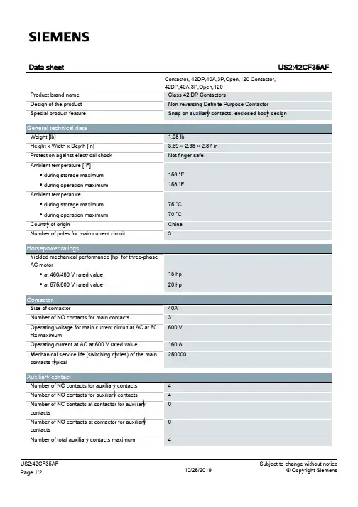
Operating current of auxiliary contacts of contactor ● at AC at 600 V
Contact rating of auxiliary contacts of contactor according to UL
10 A 10A@600VAC (A600), 11A 1/2HP 125-250VAC, 0.6A 125VDC, 0.3A 250VDC
Data sheet
Product brand name Design of the product Special product feature
US2:42CF35AF
Contactor, 42DP,40A,3P,Open,120 Contactor, 42DP,40A,3P,Open,120
Class 42 DP Contactors Non-reversing Definite Purpose Contactor Snap on auxiliary contacts, enclosed body design
vertical Surface mounting and installation Box lug
40 ... 40 lbf·in 4 AWG
Box lug
4 AWG
Quick connects, Screw-type terminals Quick Connects, Screw-type terminals
0
contacts
Number of NO contacts at contactor for auxiliary
0
contacts
Number of total auxiliary contacts maximum
综合电磁设备产品说明书
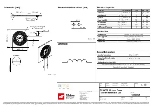
Dimensions: [mm]Scale - 1:1,5760308101760308101760308101T e m p e r a t u r eT T T 760308101Cautions and Warnings:The following conditions apply to all goods within the product series of WE-WPCC ofWürth Elektronik eiSos GmbH & Co. KG:General:•This electronic component is designed and manufactured for use in general electronic equipment.•Würth Elektronik must be asked for written approval (following the PPAP procedure) before incorporating the components into any equipment in fields such as military, aerospace, aviation, nuclear control, submarine, transportation (automotive control, train control, ship control), transportation signal, disaster prevention, medical, public information network, etc. where higher safety and reliability are especially required and/or if there is the possibility of direct damage or human injury.•Electronic components that will be used in safety-critical or high-reliability applications, should be pre-evaluated by the customer. •The component is designed and manufactured to be used within the datasheet specified values. If the usage and operation conditions specified in the datasheet are not met, the wire insulation may be damaged or dissolved.•Do not drop or impact the components, as the component may be damaged.•Würth Elektronik products are qualified according to international standards, which are listed in each product reliability report. Würth Elektronik does not warrant any customer qualified product characteristics beyond Würth Elektroniks’ specifications, for its validity and sustainability over time.•The responsibility for the applicability of the customer specific products and use in a particular customer design is always within the authority of the customer. All technical specifications for standard products also apply to customer specific products.Product specific:Soldering:•The solder profile must comply with the technical product specifications. All other profiles will void the warranty.•All other soldering methods are at the customers’ own risk.Cleaning and Washing:•Washing agents used during the production to clean the customer application might damage or change the characteristics of the wire insulation, marking or plating. Washing agents may have a negative effect on the long-term functionality of the product. Potting:•If the product is potted in the customer application, the potting material might shrink or expand during and after hardening. Shrinking could lead to an incomplete seal, allowing contaminants into the core. Expansion could damage the component. We recommend a manual inspection after potting to avoid these effects.Storage Conditions:• A storage of Würth Elektronik products for longer than 12 months is not recommended. Within other effects, the terminals may suffer degradation, resulting in bad solderability. Therefore, all products shall be used within the period of 12 months based on the day of shipment.•Do not expose the components to direct sunlight.•The storage conditions in the original packaging are defined according to DIN EN 61760-2.Packaging:•The packaging specifications apply only to purchase orders comprising whole packaging units. If the ordered quantity exceeds or is lower than the specified packaging unit, packaging in accordance with the packaging specifications cannot be ensured. Handling:•Violation of the technical product specifications such as exceeding the nominal rated current will void the warranty.•Applying currents with audio-frequency signals may result in audible noise due to the magnetostrictive material properties.•Due to heavy weight of the components, strong forces and high accelerations may have the effect to damage the electrical connection or to harm the circuit board and will void the warranty.•The temperature rise of the component must be taken into consideration. The operating temperature is comprised of ambient temperature and temperature rise of the component.The operating temperature of the component shall not exceed the maximum temperature specified.These cautions and warnings comply with the state of the scientific and technical knowledge and are believed to be accurate and reliable.However, no responsibility is assumed for inaccuracies or incompleteness.Würth Elektronik eiSos GmbH & Co. KGEMC & Inductive SolutionsMax-Eyth-Str. 174638 WaldenburgGermanyCHECKED REVISION DATE (YYYY-MM-DD)GENERAL TOLERANCE PROJECTIONMETHODCMe002.0002022-11-03DIN ISO 2768-1mDESCRIPTIONWE-WPCC Wireless PowerTransfer Transmitter Coil ORDER CODE760308101SIZE/TYPE BUSINESS UNIT STATUS PAGEImportant NotesThe following conditions apply to all goods within the product range of Würth Elektronik eiSos GmbH & Co. KG:1. General Customer ResponsibilitySome goods within the product range of Würth Elektronik eiSos GmbH & Co. KG contain statements regarding general suitability for certain application areas. These statements about suitability are based on our knowledge and experience of typical requirements concerning the areas, serve as general guidance and cannot be estimated as binding statements about the suitability for a customer application. The responsibility for the applicability and use in a particular customer design is always solely within the authority of the customer. Due to this fact it is up to the customer to evaluate, where appropriate to investigate and decide whether the device with the specific product characteristics described in the product specification is valid and suitable for the respective customer application or not.2. Customer Responsibility related to Specific, in particular Safety-Relevant ApplicationsIt has to be clearly pointed out that the possibility of a malfunction of electronic components or failure before the end of the usual lifetime cannot be completely eliminated in the current state of the art, even if the products are operated within the range of the specifications.In certain customer applications requiring a very high level of safety and especially in customer applications in which the malfunction or failure of an electronic component could endanger human life or health it must be ensured by most advanced technological aid of suitable design of the customer application that no injury or damage is caused to third parties in the event of malfunction or failure of an electronic component. Therefore, customer is cautioned to verify that data sheets are current before placing orders. The current data sheets can be downloaded at .3. Best Care and AttentionAny product-specific notes, cautions and warnings must be strictly observed. Any disregard will result in the loss of warranty.4. Customer Support for Product SpecificationsSome products within the product range may contain substances which are subject to restrictions in certain jurisdictions in order to serve specific technical requirements. Necessary information is available on request. In this case the field sales engineer or the internal sales person in charge should be contacted who will be happy to support in this matter.5. Product R&DDue to constant product improvement product specifications may change from time to time. As a standard reporting procedure of the Product Change Notification (PCN) according to the JEDEC-Standard inform about minor and major changes. In case of further queries regarding the PCN, the field sales engineer or the internal sales person in charge should be contacted. The basic responsibility of the customer as per Section 1 and 2 remains unaffected.6. Product Life CycleDue to technical progress and economical evaluation we also reserve the right to discontinue production and delivery of products. As a standard reporting procedure of the Product Termination Notification (PTN) according to the JEDEC-Standard we will inform at an early stage about inevitable product discontinuance. According to this we cannot guarantee that all products within our product range will always be available. Therefore it needs to be verified with the field sales engineer or the internal sales person in charge about the current product availability expectancy before or when the product for application design-in disposal is considered. The approach named above does not apply in the case of individual agreements deviating from the foregoing for customer-specific products.7. Property RightsAll the rights for contractual products produced by Würth Elektronik eiSos GmbH & Co. KG on the basis of ideas, development contracts as well as models or templates that are subject to copyright, patent or commercial protection supplied to the customer will remain with Würth Elektronik eiSos GmbH & Co. KG. Würth Elektronik eiSos GmbH & Co. KG does not warrant or represent that any license, either expressed or implied, is granted under any patent right, copyright, mask work right, or other intellectual property right relating to any combination, application, or process in which Würth Elektronik eiSos GmbH & Co. KG components or services are used.8. General Terms and ConditionsUnless otherwise agreed in individual contracts, all orders are subject to the current version of the “General Terms and Conditions of Würth Elektronik eiSos Group”, last version available at .Würth Elektronik eiSos GmbH & Co. KGEMC & Inductive SolutionsMax-Eyth-Str. 174638 WaldenburgGermanyCHECKED REVISION DATE (YYYY-MM-DD)GENERAL TOLERANCE PROJECTIONMETHODCMe002.0002022-11-03DIN ISO 2768-1mDESCRIPTIONWE-WPCC Wireless PowerTransfer Transmitter Coil ORDER CODE760308101SIZE/TYPE BUSINESS UNIT STATUS PAGE。
美国电子设备制造商Eaton的电磁开关器件说明书
Eaton 167814Eaton Moeller® series MSC-DE DOL starter, Ir= 0.3 - 1.2 A, 24 V 50/60 Hz, AC voltageGeneral specificationsEaton Moeller® series MSC-DE DOL starter167814MSC-DE-1,2-M17-SP(24V50/60HZ)4015081643929145 mm 272 mm 45 mm 1.174 kgCSA File No.: 012528 CEIEC/EN 60947-4-1UL Category Control No.: NKJH CSACSA-C22.2 No. 14-10 ULCSA Class No.: 3211-08 UL File No.: E123500 VDE 0660 UL60947-4-1AProduct NameCatalog Number Model CodeEANProduct Length/Depth Product Height Product Width Product Weight Certifications1.2 AIs the panel builder's responsibility. The specifications for the switchgear must be observed.7.5 kW208 - 480 V AC14 kA, 240 V, SCCR (UL/CSA)14 kA, 480 Y/277 V, SCCR (UL/CSA)0 A24 VMeets the product standard's requirements.Is the panel builder's responsibility. The specifications for the switchgear must be observed.DIN rail≤ 500 ms, main conducting paths, AC-4 cycle operationDoes not apply, since the entire switchgear needs to be evaluated.0.37 kW0.37 kWMeets the product standard's requirements.Motor Starters in System xStart - brochureSimple, flexible and safe! Distribution system for motor-starter combinationsSave time and space thanks to the new link module PKZM0-XDM32ME Product Range Catalog Switching and protecting motorsDA-DC-00004245.pdfDA-DC-00004109.pdfeaton-manual-motor-starters-msc-d-dol-starter-dimensions.epseaton-manual-motor-starters-msc-d-dol-starter-3d-drawing.epseaton-manual-motor-starters-mounting-msc-d-dol-starter-3d-drawing.eps DA-CE-ETN.MSC-DE-1,2-M17-SP(24V50_60HZ)IL03402052ZWIN-WIN with push-in technologyDA-CS-msc_de_spDA-CD-msc_de_speaton-manual-motor-starters-device-msc-d-dol-starter-wiring-diagram.epsRated operational current for specified heat dissipation (In) 10.11 Short-circuit ratingRated operational power at AC-3, 380/400 V, 50 Hz Rated operational voltageShort-circuit current rating (type E)Rated conditional short-circuit current, type 1, 480 Y/277 V Rated control supply voltage (Us) at AC, 50 Hz - min10.4 Clearances and creepage distances10.12 Electromagnetic compatibilityMounting methodCut-out periods - min10.2.5 LiftingRated power at 575 V, 60 Hz, 3-phaseRated power at 460 V, 60 Hz, 3-phase10.2.3.1 Verification of thermal stability of enclosures Rated control supply voltage (Us) at DC - min BrochuresCatalogs Certification reports DrawingseCAD model Installation instructions Installation videos mCAD modelWiring diagrams0 VFitted with:Short-circuit releaseCurrent flow times - min900 (Class 15) AC-4 cycle operation, Main conducting paths 1000 (Class 20) AC-4 cycle operation, Main conducting paths 500 (Class 5) AC-4 cycle operation, Main conducting paths 700 (Class 10) AC-4 cycle operation, Main conducting paths Note: Going below the minimum current flow time can cause overheating of the load (motor).For all combinations with an SWD activation, you need not adhere to the minimum current flow times and minimum cut-out periods.Number of pilot lightsShort-circuit current rating (high fault at 600 V)100 kA, Fuse, SCCR (UL/CSA)3 A, Class J/CC, max. Fuse, SCCR (UL/CSA)Rated control supply voltage (Us) at AC, 50 Hz - max24 V10.8 Connections for external conductorsIs the panel builder's responsibility.Coordination class (IEC 60947-4-3)Class 2Rated conditional short-circuit current, type 1, 600 Y/347 V0 APower consumption, sealing, 50 Hz2.1 CO, Coil in a cold state and 1.0 x UsAmbient operating temperature - max55 °CRated operational power at AC-3, 220/230 V, 50 Hz0.18 kWConnection to SmartWire-DTNoNumber of command positionsStatic heat dissipation, non-current-dependent Pvs2.1 WElectrical connection type of main circuitScrew connectionElectrical connection type for auxiliary- and control-current circuit Screw connectionRated control supply voltage (Us) at DC - max0 V10.9.3 Impulse withstand voltageIs the panel builder's responsibility.Ambient operating temperature - min-25 °C10.6 Incorporation of switching devices and componentsDoes not apply, since the entire switchgear needs to be evaluated.10.5 Protection against electric shockDoes not apply, since the entire switchgear needs to be evaluated.ClassAdjustable10.13 Mechanical functionThe device meets the requirements, provided the information in the instruction leaflet (IL) is observed.10.2.6 Mechanical impactDoes not apply, since the entire switchgear needs to be evaluated.10.9.4 Testing of enclosures made of insulating materialIs the panel builder's responsibility.10.3 Degree of protection of assembliesDoes not apply, since the entire switchgear needs to be evaluated.Heat dissipation per pole, current-dependent Pvid0.4 WActuating voltage24 V 50/60 HzVoltage typeACSwitching capacity (auxiliary contacts, general use)1 A, 250 V DC, (UL/CSA)15 A, 600 V AC, (UL/CSA)Overload release current setting - min0.3 AEquipment heat dissipation, current-dependent Pvid1.2 WHeat dissipation capacity Pdiss0 WRated operational current (Ie)16.7 AAssigned motor power at 460/480 V, 60 Hz, 3-phase0.5 HPNumber of auxiliary contacts (normally closed contacts)Rated conditional short-circuit current (Iq), type 2, 380 V, 400 V, 415 V0 A10.2.3.2 Verification of resistance of insulating materials to normal heatMeets the product standard's requirements.10.2.3.3 Resist. of insul. mat. to abnormal heat/fire by internal elect. effectsMeets the product standard's requirements.Overload release current setting - max1.2 A10.9.2 Power-frequency electric strengthIs the panel builder's responsibility.Overvoltage categoryIIIDegree of protectionIP20NEMA OtherPollution degree3Rated control supply voltage (Us) at AC, 60 Hz - min24 V10.7 Internal electrical circuits and connectionsIs the panel builder's responsibility.Rated impulse withstand voltage (Uimp)6000 V ACConnectionScrew terminals10.10 Temperature riseThe panel builder is responsible for the temperature rise calculation. Eaton will provide heat dissipation data for the devices.FunctionsTemperature compensated overload protectionRated conditional short-circuit current (Iq), type 2, 230 V0 ATypeStarter with electronic trip unit10.2.2 Corrosion resistanceMeets the product standard's requirements.10.2.4 Resistance to ultra-violet (UV) radiationMeets the product standard's requirements.10.2.7 InscriptionsMeets the product standard's requirements.Short-circuit release (Irm) - max186 ARated control supply voltage (Us) at AC, 60 Hz - max24 VRated operational current (Ie) at AC-3, 380 V, 400 V, 415 V 1.2 AModelDirect starterNumber of auxiliary contacts (normally open contacts)1AltitudeMax. 2000 mSwitching capacity (auxiliary contacts, pilot duty)P300, DC operated (UL/CSA)A600, AC operated (UL/CSA)Eaton Corporation plc Eaton House30 Pembroke Road Dublin 4, Ireland © 2023 Eaton. All Rights Reserved. Eaton is a registered trademark.All other trademarks areproperty of their respectiveowners./socialmedia。
电磁开关 传感器技术数据手册说明书
GENERAL DATALife Expectancy Minimum operations Mechanical Electrical Light Duty3 x 105 at 3A, 120VACMedium Duty 1.8 x 10⁵ at 6A, 120VAC Operate Time (typical) 5ms at nominal coil voltageRelease Time (typical) 2ms at nominal coil voltage(with no coil suppression)Dielectric Strength 750Vrms contact to contact(at sea level for 1 min.) 2000Vrms contact to coil except hermeticallysealed version which is 1600Vrms Insulation Resistance 1000 megohms min. at 20°C, 500VDC, 50% RHDropoutGreater than 5% of nominal coil voltage Ambient TemperatureAt nominal coil voltageOperating-55°C (-67°F) to 90°C (194°F) Class B -55°C (-67°F) to 115°C (239°F) Class F Storage-55°C (-67°F) to 130°C (266°F) Class B -55°C (-67°F) to 155°C (311°F) Class F Vibration 0.062" DA at 10–55 Hz, 10 g at 55–110 Hz Shock 10gEnclosure P B T polyesterTerminalsTinned copper alloy, P.C.Max. Solder Temp.270°C (518°F)Max. Solder Time 5 seconds Max. Solvent Temp.80°C (176°F)Max. Immersion Time 30 seconds WeightApprox. 11 gramsCOILPowerAt Pickup Voltage (typical)Standard coil: 250mW (48V coil: 341mW) Sensitive coil: 175mW (48V coil: 182mW)Max. Continuous Class B: 2.0W 20°C (68°F) ambientDissipation1.6W 40°C (104°F) ambientClass F: 2.5W 20°C (68°F) ambientTemperature Rise2.1W 40°C (104°F) ambientAt nominal coil voltage Standard coil: 38°C (68°F)Sensitive coil: 28°C (50°F)TemperatureMax. 105°C (221°F) Class A Max. 130°C (266°F) Class B Max. 155°C (311°F) Class FMINIATUREPC BOARD RELAYFEATURES •Subminiature size•High sensitivity, 110mW pickup •Coils to 48VDC•Hermetically sealed version available•Epoxy sealed for automatic wave soldering •Withstands 4kV standard IEEE Lightning Surge•Withstands 6kV IEEE Lightning Surge (special order)•Class B insulation (130°C) standard•Class F insulation (155°C) version available •UL, CUR file E44211CONTACTSArrangement SPDT (1 Form C)SPST (1 Form A)RatingsLight DutyResistive load:Max. switched power: 100W or 600VA Max. switched current: 3AMax. switched voltage: 150VDC or 300VAC UL Rating: See chart on Page 3Medium DutyMax. switched power: 180W or 1800VA Max. switched current: 6AMax. switched voltage: 150VDC or 300VAC UL Rating: See chart on Page 3Material Light duty: SilverMedium duty: Silver nickel Resistance< 100 milliohms initiallyNOTES1.All values at 20°C (68°F).2.Relay may pull in with less than “Must Operate” value.3.Other coil resistances and sensitivities available upon request.4.Unsealed relays should not be dip cleaned.5.Specifications subject to change without notice.1 x 107•VDE approved versions available (Class A Insulation only)RELAY ORDERING DATARELAY ORDERING DATA - VDE APPROVED VERSIONSUL, CUR RATINGSLight Duty2A at 28VDC or 300VAC 1/8HP at 120 VAC1/10HP at 120/240 VAC (100,000 cyc)1.2/0.6A at 120/240 VAC, Pilot Duty 100,000 cyc 3.0/1.5A at 120/240 VAC General Use 100,000 cyc Medium Duty 6A at 28VDC or 300VAC1/8 HP at 120/240 VAC (100,000 cyc)1.5/0.8 A at 120/240 VAC, Pilot Duty 100,000 cyc 3.8/1.9 A at 120/240 VAC General Use 100,000 cycVDE RATINGSSealed5A at 250VAC resistive, 10,000 cyclesUnsealed 6A at 250VAC resistive, 50,000 cyclesHERMETICALLY SEALED VERSION3/29/21。
电磁滤波器DC1-344D1FN-A66N的说明书
IEC/EN 61439 design verification
10.2 Strength of materials and parts
Efficiency Maximum leakage current to ground (PE) without motor Fitted with
Frame size Motor feeder
Note
Note Note 150 % Overload Note 150 % Overload maximum permissible cable length
Variable frequency drives
DC1
Ue
400 V AC, 3-phase
480 V AC, 3-phase
U2
400 V AC, 3-phase
480 V AC, 3-phase
ULN
V
380 (-10%) - 480 (+10%)
Ie
A
4.1
Rated operational current at a switching frequency of 16 kHz and an ambient air temperature of +40 °C
DATASHEET - DC1-344D1FN-A66N
Variable Frequency Drive, 3-/3- 400 V, 4.1 A, 1.5 kW, EMC-Filter
Part no.
DC1-344D1FN-A66N
Catalog No.
169479
Eaton Catalog No. DC1-344D1FN-A66N
Frame size Connection to SmartWire-DT
TDK 大功率PQ系列Mn-Zn大尺寸磁铁芯说明书
F E R R I T E SJuly 2019Mn-ZnLarge Size Ferrite Cores for High Power PQ seriesPlease be sure to read this manual thoroughly before using the products.The products listed on this catalog are intended for use in general electronic equipment (AV equipment, telecommunications equipment, home appliances, amusement equipment, computer equipment, personal equipment, office equipment, measurement equipment, industrial robots) under a normal operation and use condition.The products are not designed or warranted to meet the requirements of the applications listed below, whose performance and/or quality require a more stringent level of safety or reliability, or whose failure, malfunction or trouble could cause serious damage to society, person or property.When using the products for specific purposes, please first make confirmations in areas such as safety, reliability, and quality.Please understand that we are not in a position to be held responsible for any damage or the like caused by any use exceeding the range or conditions of this specification sheet or by any use in the specific applications.(1) Aerospace/Aviation equipment(2) T ransportation equipment (electric trains, ships, etc.)(3) Medical equipment(4) Power-generation control equipment(5) Atomic energy-related equipment(6) Seabed equipment(7) T ransportation control equipment (8) Public information-processing equipment(9) Military equipment(10) Electric heating apparatus, burning equipment(11) Disaster prevention/crime prevention equipment(12) Safety equipment(13) Other applications that are not considered general-purposeapplicationsWhen using this product in general-purpose standard applications, you are kindly requested to take into consideration securing protection circuit/equipment or providing backup circuits, etc to ensure higher safety.REMINDERS FOR USING THESE PRODUCTSLarge Size Ferrite Cores for High Power FEATURESAPPLICATIONPART NUMBER CONSTRUCTIONRANGE OF USE AND STORAGE TEMPERATUREOverview of the PQ SeriesPE22PQ78×39×42Material Core shapeWidth Height when assembledThicknessPE22PQ783942PC401078770Temperature rangeOperating temperature Storage temperature °C °C –30 to +105–30 to +85Product compatible with RoHS directiveHalogen-freeMn-Zn PQ Cores SHAPES AND DIMENSIONSPart No.Dimensions(mm)A1A2BøC2D E2HPE22 PQ78⨯39⨯42PC40 PQ78⨯39⨯4278.5±1.542.0±0.869.0min.25.5±0.539.4±0.660.0min.25.8±1.0 PE22 PQ107⨯87⨯70PC40 PQ107⨯87⨯70107.0±2.070.0±1.593.7min.41.0±1.087.0±1.572.5min.56.0±1.5Part No.Effective parameterElectricalcharacteristics Core factor Effectivecross-sectionalareaEffectivemagnetic pathlengthEffectivecore volumeWeigh(approx.)A L-valueC1(mm–1)C2⨯10–2(mm–3)A e(mm2)e(mm)V e(mm3)(g)(nH/N2)1kHz0.4A/m23°CPE22 PQ78⨯39⨯42 PC40 PQ78⨯39⨯420.247300.051530480 119 569003043047940±25%9790±25%PE22 PQ107⨯87⨯70 PC40 PQ107⨯87⨯700.14260 0.009989 1428 204 2906001560156014570±25%18210±25%PE22PQ78×39×42MaterialCoreshapeWidthHeight whenassembledThicknessSHAPES AND DIMENSIONS*The symbol followed A min. value shows minimum cross-sectional area part.C is center pole part, L: is outer pole part, B is the back part.• Available customaize core like this. Please specify when ordering. Calculated output power (forward converter mode): 1.6kW (100kHz)NI limit vs. A L -valueA L -value vs. Air gap lengthEffective parameter Electricalcharacteristics Core factorEffectivemagnetic path lengthEffectivecross-sectional area Effective core volumeCross-sectional center pole areaMinimum cross-sectional area Winding cross-sectional area Weigh (approx.)A L -valueC 1C 2⨯10–2 e Ae Ve A cA min.*Acw (mm –1)(mm –3)(mm)(mm 2)(mm 3)(mm 2)(mm 2)(mm 2)(g)(nH/N 2)1kHz 0.4A/m 23°C0.24730.0515311948056900510510C*5703047940±25%The 20% and 40% graph shows when a 20% and 40% drop from the initial A L -value has been made due to the DC superimposition.SHAPES AND DIMENSIONS*The symbol followed A min. value shows minimum cross-sectional area part.C is center pole part, L: is outer pole part, B is the back part.• Available customaize core like this. Please specify when ordering. Calculated output power (forward converter mode): 1.7kW (100kHz)NI limit vs. A L -valueA L -value vs. Air gap lengthEffective parameter Electricalcharacteristics Core factorEffectivemagnetic path lengthEffectivecross-sectional area Effective core volumeCross-sectional center pole areaMinimum cross-sectional area Winding cross-sectional area Weigh (approx.)A L -valueC 1C 2⨯10–2 e Ae Ve A cA min.*Acw (mm –1)(mm –3)(mm)(mm 2)(mm 3)(mm 2)(mm 2)(mm 2)(g)(nH/N 2)1kHz 0.4A/m 23°C0.24730.0515311948056900510510C*5703049790±25%The 20% and 40% graph shows when a 20% and 40% drop from the initial A L -value has been made due to the DC superimposition.SHAPES AND DIMENSIONS*The symbol followed A min. value shows minimum cross-sectional area part.C is center pole part, L: is outer pole part, B is the back part.• Available customaize core like this. Please specify when ordering. Calculated output power (forward converter mode): 8.3kW (100kHz)NI limit vs. A L -valueA L -value vs. Air gap lengthEffective parameter Electricalcharacteristics Core factorEffectivemagnetic path lengthEffectivecross-sectional area Effective core volumeCross-sectional center pole areaMinimum cross-sectional area Winding cross-sectional area Weigh (approx.)A L -valueC 1C 2⨯10–2 e Ae Ve A cA min.*Acw (mm –1)(mm –3)(mm)(mm 2)(mm 3)(mm 2)(mm 2)(mm 2)(g)(nH/N 2)1kHz 0.4A/m 23°C0.14260.009989204142829060013201320C*1540156014570±25%The 20% and 40% graph shows when a 20% and 40% drop from the initial A L -value has been made due to the DC superimposition.SHAPES AND DIMENSIONS*The symbol followed A min. value shows minimum cross-sectional area part.C is center pole part, L: is outer pole part, B is the back part.• Available customaize core like this. Please specify when ordering. Calculated output power (forward converter mode): 9.0kW (100kHz)NI limit vs. A L -valueA L -value vs. Air gap lengthEffective parameter Electricalcharacteristics Core factorEffectivemagnetic path lengthEffectivecross-sectional area Effective core volumeCross-sectional center pole areaMinimum cross-sectional area Winding cross-sectional area Weigh (approx.)A L -valueC 1C 2⨯10–2 e Ae Ve A cA min.*Acw (mm –1)(mm –3)(mm)(mm 2)(mm 3)(mm 2)(mm 2)(mm 2)(g)(nH/N 2)1kHz 0.4A/m 23°C0.14260.009989204142829060013201320C*1540156018210±25%The 20% and 40% graph shows when a 20% and 40% drop from the initial A L -value has been made due to the DC superimposition.。