技术要求翻译
设备安装技术要求-英文翻译
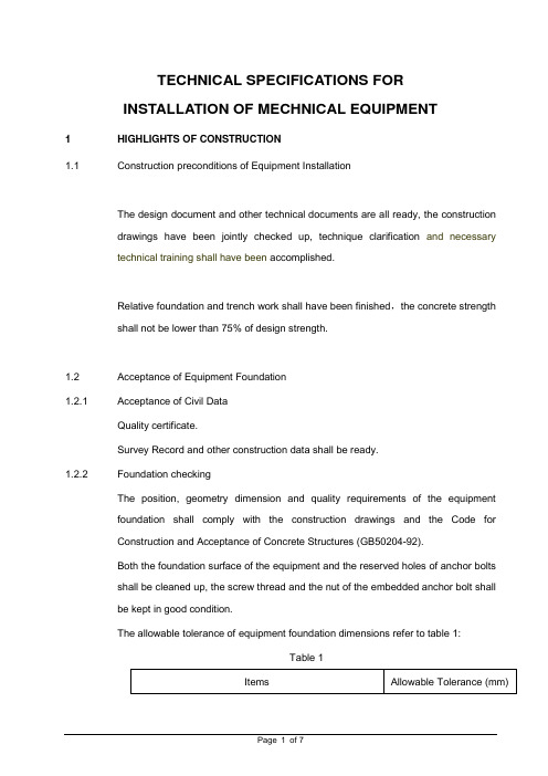
TECHNICAL SPECIFICATIONS FORINSTALLATION OF MECHNICAL EQUIPMENT1 HIGHLIGHTS OF CONSTRUCTION1.1 Construction preconditions of Equipment InstallationThe design document and other technical documents are all ready, the constructiondrawings have been jointly checked up, technique clarification and necessarytechnical training shall have been accomplished.Relative foundation and trench work shall have been finished,the concrete strengthshall not be lower than 75% of design strength.1.2 Acceptance of Equipment Foundation1.2.1 Acceptance of Civil DataQuality certificate.Survey Record and other construction data shall be ready.1.2.2 Foundation checkingThe position, geometry dimension and quality requirements of the equipmentfoundation shall comply with the construction drawings and the Code forConstruction and Acceptance of Concrete Structures (GB50204-92).Both the foundation surface of the equipment and the reserved holes of anchor boltsshall be cleaned up, the screw thread and the nut of the embedded anchor bolt shallbe kept in good condition.The allowable tolerance of equipment foundation dimensions refer to table 1:Table 1Page 1 of 71.3 Unpacking Inspection of EquipmentUnpacking inspection of equipment shall be executed under the supervision of theOwner’s personnel, Contractor shall inspect the following items:Appearance , quantity, specification and model of the equipmentPacking list and other technical dada.During the inspection Contractor shall keep all the records.Equipment , spare parts and special tools shall be carefully kept.1.4 Installation of Equipment1.4.1 Positioning and Aligning of EquipmentThe baseline of installation shall be designated accord with construction drawing andrelating axis, edge line or elevation line before equipment positioning.The allowable tolerance of of the distance from plane installation bench mark toactual foundation axis or between actual shop wall axis and edge line is ±20mm.Refer to Table 2 for the allowable tolerance of plane position and elevation of thepositioning plane, line or point to bench mark:Table2The allowable tolerance of equipment installation refers to table 3: Table 31.4.2 Anchor BoltThe Anchor bolt in the reserved hole shall accord with the requirement ofconstruction drawing and design document; the requirement below must be followedif no other special instructions are available:(1) Anchor bolt shall be vertical in reserved hole free of inclining.(2) The distance between any part of anchor bolt to the hole wall shall be largerthan 15mm, and the bolt end shouldn’t touch hole bottom.(3) The oil dirt and oxidized surface of anchor bolt shall be clear away, a littlegrease shall be applied to the screw thread of the anchor bolt.(4) There shall be no distance between the nut and the gasket, and so are thegasket and the pedestal of the equipment.(5) Bolt shall extend out of nut after nut fastening; the exposed length is about1/3-2/3 of the diameter value of the bolt.(6) The anchor blot shall be fastened while concrete strength in reserved reachesmore than than 75% designed value, the fastening strength shall be evenly.1.4.3 Iron ShimThe shim size for level adjusting of equipment shall accord with the requirement ofconstruction drawings or technical documents.The common wedge shim and flat shim shall be selected according to Appendix 5 ofthe Construction & Acceptance Criterion of Machine & Equipment Installation Works(GB50231-98).1.4.4 GroutingThe grouting between the foundation and pedestal of the equipment/the reservedhole of the anchor bolt shall comply with the Code for Construction and Acceptanceof Concrete Structures (GB50204-92).The grouting place shall be cleaned up before grouting. The concrete grade used forgrouting is one grade higher than that used for foundation or ground. Groundingshouldn’t make anchor bolt inclined or affect installing precision of the equipment.The thickness of grouting layer shall accord with design requirement, commonly notless than 25mm.The outer forms shall be laid before grouting, the distance of outer forms from outeredge of equipment base shouldn’t less than 60mm; Float coat shall be applied to thesurface after removal of forms.The inner forms shall be laid when complete grouting is not needed under equipmentbase and grouting layer would bear load of equipment.1.4.5 Assembly of EquipmentThe assembly of equipment shall accord with the requirement of constructiondrawings, technical documents of manufacturer and Code for Construction &Acceptance of Machine & Equipment Installation Works (GB50231-98).Before the equipment assembly, the Contractor shall be familiar with the equipmentstructure and the technical requirements of equipment assembly. Recheck andcleaning treating on match dimension, relating precision, match face and sliding faceof assembly parts shall be done, and the assembly shall be performed according tomarks and assemble sequence.As to equipment or parts have inner cavity, careful check and clearance must bedone before concealing avoid any foreign substance contained in it.As to oil tank or water tank that difficult to disassembly, check and fix, leakageexamination must be done before assembly.1.4.6 Installation of Equipment AccessoriesThe installation of tower and inner parts of equipment shall accord with therequirement of construction drawings and Code for Construction & Acceptance ofMachine & Equipment Installation Works (GB50231-98).The installation of inner parts of pump shall accord with the requirement ofconstruction drawings and Construction, Code for Construction and Acceptance ofCompressor, Fan and Pump Installation Works (GB50275-98).The installation, pressure testing of accessory pipe shall accord with the requirementof construction drawings and Code for Construction and Acceptance of IndustrialPiping Works (GB50236-98).The installation of accessory ladder, platform shall accord with the requirement ofconstruction drawings and Code for Construction and Acceptance of Steel StructureWorks (GB50205-95).1.4.7 Equipment TestAfter the installation completed, all the welding seams of pressure vessel shall bechecked according to the Assessment on Welding Technology of Pressure Vessel(JB4708-92) and make record.Pressure experiment shall be performed to pressure container accord withconstructing instructions and design requirement after installation.The pressure & leakage test shall be executed according to the ConstructionExplanation and the Design Requirements after the installation of stove type andfamiliar equipments that have water double layer.1.4.8 Cleaning and Purging of EquipmentWhen the installation of pump equipment completed, cleaning and purged of suchequipment must be carried out according to construction drawings and Construction,Checking and Construction, Code for Construction and Acceptance of Compressor,Fan and Pump Installation Works (GB50275-98).The cleaning and purging of static equipment must be performed after installationaccording to construction drawings and Code for Construction & Acceptance ofMachine & Equipment Installation Works (GB50231-98).1.4.9 Test-run of EquipmentThe conditions, contents and procedure shall be ready before equipment test-run, asspecified in Code for Construction & Acceptance of Machine & EquipmentInstallation Works (GB50231-98).Make good test-run record during the test-run operation.After test-run of equipment, turn off power supply, drain out water and vent air andclean as per Code for Construction & Acceptance of Machine & EquipmentInstallation Works (GB50231-98).1.4.10 Taking-over, Inspection and Acceptance of the Equipment Installation WorksAfter all the working procedure of equipment have finished, the Contractor shall packup all the construction documents and perform inspection & acceptance of theEquipment Installation Works under the supervision of relative personnel if thetest-run of equipment is successful and meet the requirements of Design and Relative Specifications.At last the Contractor shall go through the formalities of taking-over procedure.ATTACHED ILLUMINATION:This Standard Is Kept By Technique Department.This Standard Was Prepared By Construction Management Department.THE MAIN DRAFTSMAN OF THIS STANDARD:Xu QingChecked by :Xu Xingguo / Wu BenlunApproved by :。
技术要求翻译
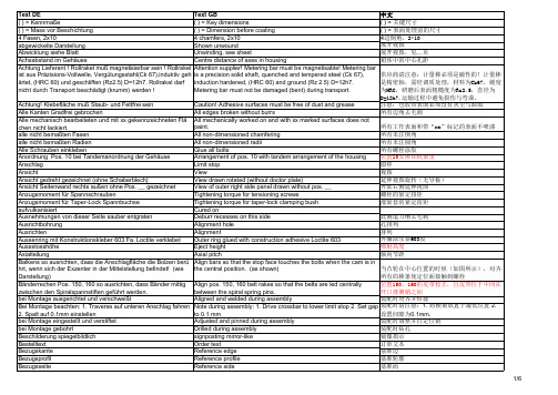
所有未注圆角
Alle Schrauben einkleben
Glue all bolts
所有螺栓涂胶
Anordnung Pos. 10 bei Tandemanordnung der Gehäuse Anschlag
Arrangement of pos. 10 with tandem arrangement of the housing Limit stop
Drilled during assembly
装配时钻孔
Beschilderung spiegelbildlich Bestelltext
signposting mirror-like Order text
镜像指示 订单文本
Bezugskante
Reference edge
基准边
Bezugsprofil
chen nicht lackiert. alle nicht bemaßten Fasen
paint. All non-dimensioned chamfering
所有工作表面和带“xx”标记的表面不喷漆 所有未注倒角
alle nicht bemaßten Radien
All non-dimensioned radii
hrt, wenn sich der Exzenter in der Mittelstellung befindet! (wie the central position. (as shown)
当凸轮在中心位置的时候(如图所示),对齐
Darstellung)
所有的棒条使定位面接触到螺栓
Bänderrechen Pos. 150, 160 so ausrichten, dass Bänder mittig Align pos. 150, 160 belt rakes so that the belts are led centrally
常用技术翻译
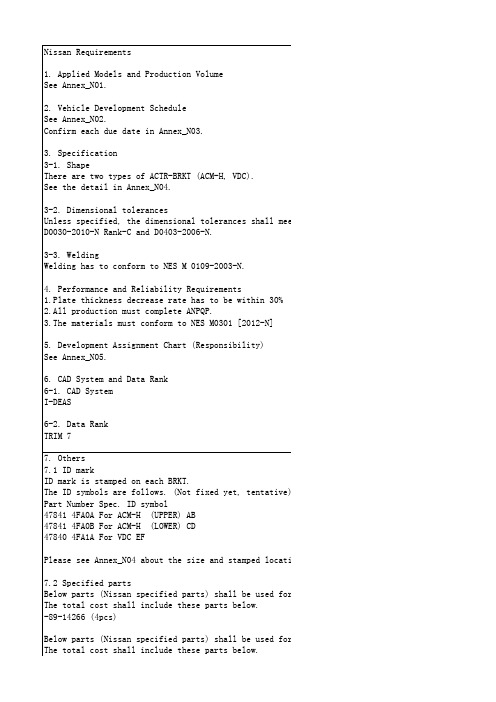
-18316 S3260 (4pcs) -81-10630-2G (2pcs) -89-18306-2A (2pcs)-89-14266 (4pcs)Below parts (Nissan specified parts) shall be used for 47840 4FA1A.The total cost shall include these parts below.-49728 6P00A (4pcs)-18316 S3260 (4pcs)-81-10630-2G (2pcs)-89-18306-2A (2pcs)-89-14266 (2pcs)-82-76625 (2pcs)8. Notes1. This technical sheet gives the supplier the minimum specification of the BRKT for Brake System t quote the cost. If the specifications stated in this RFQ are not enough for the cost quotation, all the unclear items must be informed to Nissan before the cost quotation.2. If there are any difficulties or concerns about BRKT shape for the production, please contact with Nissan engineers and provide counter proposal.3. Nissan will not accept any cost increasing request for design change by the supplier matters without any changes of Nissan specification.4. If you need the 3D data of these BRKT for cost estimation, please inform to Nissan engineer.5. The sample parts (1 part each) for vibration test must be delivered by September 14th.6. To contact Nissan, please send an e-mail below.Driving Control Engineering Development Department (XN0)ISHIZUKA MOTOI : motoi-ishizuka@mail.nissan.co.jp7. Others7.1 ID markID mark is stamped on each BRKT.The ID symbols are follows. (Not fixed yet, tentative)Part Number Spec. ID symbol47841 4FA0A For ACM-H (UPPER) AB47841 4FA0B For ACM-H (LOWER) CD47840 4FA1A For VDC EFPlease see Annex_N04 about the size and stamped location.7.2 Specified partsBelow parts (Nissan specified parts) shall be used for 47841 4FA0A & 47841 4FA0B.The total cost shall include these parts below.-89-14266 (4pcs)Below parts (Nissan specified parts) shall be used for 47840 4FA1A.The total cost shall include these parts below.-49728 6P00A (4pcs)-18316 S3260 (4pcs)-81-10630-2G (2pcs)-89-18306-2A (2pcs)-89-14266 (2pcs)-82-76625 (2pcs)8. Notes1. This technical sheet gives the supplier the minimum specification of the BRKT for Brake System t quote the cost. If the specifications stated in this RFQ are not enough for the cost quotation, all the unclear items must be informed to Nissan before the cost quotation.2. If there are any difficulties or concerns about BRKT shape for the production, please contact with Nissan engineers and provide counter proposal.3. Nissan will not accept any cost increasing request for design change by the supplier matters without any changes of Nissan specification.4. If you need the 3D data of these BRKT for cost estimation, please inform to Nissan engineer.5. The sample parts (1 part each) for vibration test must be delivered by September 14th.6. To contact Nissan, please send an e-mail below.Driving Control Engineering Development Department (XN0)ISHIZUKA MOTOI : motoi-ishizuka@mail.nissan.co.jpwith Nissan engineers and provide counter proposal.3. Nissan will not accept any cost increasing request for design change by the supplier matters without any changes of Nissan specification.).thin 30%012-N]ity)-18316 S3260(4件)-81-10630-2G(2个)-89-18306-2A(2个)ow. ow.-89-14266(4件)以下部分(日产指定的部分)应用于为478404FA1A。
(完整版)英文图纸技术翻译

340121-05-HNOTES :(UNLESS OTHERWISE SPECIFIED):备注:(除非另有说明)1. MATERIAL :RTP 900-P1700 ZC-700458 BLUE (UDEL POLYSULFONE ,COLOR BLUE).材料:RTP 900-P1700 RTP 900-P1700 蓝色(聚砜,蓝色)NO USED OR RECYCLED MATERIAL PERMITTED .不允许使用用过的或者回收的材料PROVIDED RAW MATERIAL LOT CERTIFICATION WITH EACH SHIPMENT WHICH INCLUDES SUPPLIER NAME LOT NUMBER ,AND MATERIAL TYPE OR SPECIFICATION NUMBER .提供每一次交付来料原材料批号认证,包括供应商名称批号,材料类型或者规格编号2. ALL EJECTOR PIN AND GATING VESTIGE TO BE FLUSH OR RECESSED WITHIN .005 OF SURFACE.所有的顶针和水口残留要与部品表面齐平,深入表面最大不能超过0.005INTUITIVE SURGICAL ENGINEER TO APPROVE ALL GATE AND EJECTOR PIN LOCATIONS .要与客户确认水口和顶针位置3. NO CRACKS ,FLASH,SINKS,OR KNIT LINES PERMITTED UNLESS APPROVED BY INTUITIVE SURGICAL . 不能有裂纹,披峰,缩水,熔接线,除非客户同意VISUALLY INSPECT FOR COMPLETE FILL AND IRREGULARITIES肉眼检查一下打满胶的部品和其他不良4. ALL MOLD RELEASE MUST BE APPROVED BY INTUITIVE SURGICAL ENGINEERING PRIOR TOUSE .脱模剂要经过外观工程科同意后使用5. DIAMETRICAL TAPER TO CONFORM TO ISO 594/1-1986 (LUER FITTING ).直径的锥形符合ISO 594/1 - 1986(鲁尔接口配件)USE GO/NOGO GAGE DEFINED IN ISO 594/1-1986 ,FIGURE 3C (ISI PN 710014)TO INSPECT CAVITY .通止规使用参考ISO 594/1-1986,检查前模用FIGURE 3C (ISI PN 710014)6. NOT FULLY DIMENSIONED OBTAIN MISSING INFORMATION FROM CAD FILES .没标注的尺寸参见CAD图纸7. PARTS TO BE CLEAN , WITH NO CONTAMINATION OR LUBRICANT .部品要干净,没有污染物质或润滑剂NO VISIBLE PARTICULATE WHEN EXAMINED WITHOUT MAGNIFICATION .用肉眼检查,不要有可见微粒8. PACKAGE IN CLEAN CLEAR PLASTIC BAGS .包装使用干净的透明塑料袋LABEL PACKAGING WITH INTUITIVE ’S PART NUMBER , REVISION (EG .340121-01-H),PURCHASE ORDER NUMBER,AND QUANTITY.包装标签上要有:直观的零件号,修订版本(如.340121-01-H),采购订单号和数量。
技术要求翻译

The delivery kit should include service kits for commissioning, as well as maintenance for 500 and 1000 hours.
机组调试,和500以及1000小时维保
Warranty: Original manufacturer's warranty
- electronic control system of the compressor unit assemblies in Russian with an alert on the LCD screen about the following parameters: working pressure, fuel level, operating hours counter, air temperature at the outlet of the compressor element and out of the outlet, engine oil pressure, engine oil temperature, number Engine speed, compressor oil level, engine coolant level, ready-to-start state, start state, idle state, load status, refrigerated state Emergency stop status, warm-up status;
带有离心除液的额外柴油滤器
- a system that ensures uninterrupted start-up at a temperature of -25 ° C;
机械图纸中英文翻译
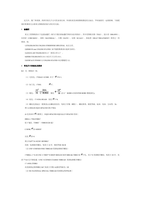
近几年,我厂和英国、西班牙的几个公司有业务往来,外商传真发来的图纸都是英文标注,平时阅看有一定的困难。
下面把我们积累的几点看英文图纸的经验与同行们交流。
1标题栏英文工程图纸的右下边是标题栏(相当于我们的标题栏和部分技术要求),其中有图纸名称(TILE)、设计者(DRAWN)、审查者(CHECKED)、材料(MATERIAL)、日期(DATE)、比例(SCALE)、热处理(HEAT TREATMENT)和其它一些要求,如:1)TOLERANCES UNLESS OTHERWISE SPECIFIAL 未注公差。
2)DIMS IN mm UNLESS STATED 如不做特殊要求以毫米为单位。
3)ANGULAR TOLERANCE±1°角度公差±1°。
4)DIMS TOLERANCE±0.1未注尺寸公差±0.1。
5)SURFACE FINISH 3.2 UNLESS STATED未注粗糙度3.2。
2常见尺寸的标注及要求2.1孔(HOLE)如:(1)毛坯孔:3"DIAO+1CORE 芯子3"0+1;(2)加工孔:1"DIA1";(3)锪孔:锪孔(注C'BORE=COUNTER BORE锪底面孔);(4)铰孔:1"/4 DIA REAM铰孔1"/4;(5)螺纹孔的标注一般要表示出螺纹的直径,每英寸牙数(螺矩)、螺纹种类、精度等级、钻深、攻深,方向等。
如:例1.6 HOLES EQUI-SPACED ON 5"DIA(6孔均布在5圆周上(EQUI-SPACED=EQUALLY SPACED均布)DRILL 1"DIATHRO'钻1"通孔(THRO'=THROUGH通)C/SINK22×6DEEP沉孔22×6例2.TAP7"/8-14UNF-3BTHRO'攻统一标准细牙螺纹,每英寸14牙,精度等级3B级(注UNF=UNIFIED FINE THREAD美国标准细牙螺纹)1"DRILL 1"/4-20 UNC-3 THD7"/8 DEEP 4HOLES NOT BREAK THRO钻1"孔,攻1"/4美国粗牙螺纹,每英寸20牙,攻深7"/8,4孔不准钻通(UNC=UCIFIED COARSE THREAD 美国标准粗牙螺纹)1"-14NS-2THRO攻美国固定特种螺纹M1",每英寸牙数14,精度等级为二级(注NS=NATIONAL SPECIAL THREAD:美国固定特种标准)2.2倒角(CHAMFER)例1/8×45°BEV倒角1/8×45°(注BEV=BEVEI,斜面)1.5×45°CHAM倒角1.5×45°(注CHAM=CHAMFER倒角)2.3方(SQUARE)例 5"SQUARE5"×5"方2.4剖视(SECTION)例 SECTION A-A A-A剖面2.5圆角半径例1"R R1"RADIUS MUST BE SMOOTH AND BLEND INTO FACE圆弧必须光滑且与平面相切2.6加工余量例 DOTTED LINES INDICATED MAX FINISH 1"/8虚线表示最大加工余量1"/82.7零件标记例USE 5"/16 RAISED HAIRLINE LET-TERS MARKING ON ONE SIDE OF BODY用突起高为5"/16的细实线字母在本体一侧打标记3关于铸锻件的技术要求例1.FORGING MUST BE ANNEALED TO BE BELOW 203 BRINELL HARDNESS 锻件必须退火处理,布氏硬度<203例2.NORMALIZE TO 163-207BHNMUST BE FREE OF SCALE & RUST锻件正火处理,布氏硬度163-207,锻件表面不得有氧化皮和锈蚀例3.FORGING TO BE SHOT OR SAND BLASTED锻件需经喷丸或喷砂处理例4.UNLESS OTHERWISE SPECIFIED DRAFT ANGLES 7°未注明锻造拔模斜度7°例5.CAST TO BE FREE OF EXCESSIVE FLASH 铸件不得有过多的毛边例6.DRAFT ANGLE 2° UNLESS OTHER-WISE SPECIFIED 未注明铸造拔模斜度2°总之,看英文机械工程图纸并不是高不可攀,只要坚持常看,熟记部分单词即可。
图纸技术要求英汉翻译

图纸信息1.Dimensions apply after finished.图纸尺寸应用于成品。
2.Unless otherwise specified,the following profile and positional tolerance applies :未注尺寸的,按照轮廓度和位置度公差。
3.Condition part for safe handling per UL#1439. 规定以UL#1439文件安全加工。
4.Surface treatment:electroless nickel .0001-.0002 thk.表面处理:无电沉镍,厚度.0001-.00025.Material:grey cast iron one percent nickel.材料:含1%镍的灰铸铁。
6.Draft adds mass.图样增大面积。
7.Normalize before machining.机加工前正火(热处理,解除内应力)8.Unless otherwise specified,draft angle to be 2°.未注公差,图样角度给到2度。
9.Straight knurl this surface.此表面直纹。
10.Check when restrained to datum A.以A基准检查工件。
11.Inside and outside radii 0.06 typ. 內外R角0.06.12.All bins and walls to be 0.38 thk unless otherwise specified.未注明,加强肋和壁给定0.38厚度.13.Casting to be stress relieved.铸造用来去除內应力。
14. A slip fit hole.间隙配合孔.Press fit.过盈配合。
15.An interference fit.过渡配合。
整车信息安全技术要求英文版
整车信息安全技术要求英文版English:"Vehicle information security technology requirements encompass a multifaceted approach to safeguarding the integrity, confidentiality, and availability of data within the vehicle's ecosystem. These requirements entail robust encryption mechanisms to protect sensitive information from unauthorized access or tampering, secure authentication protocols to ensure only authorized users can interact with the vehicle's systems, and stringent intrusion detection and prevention systems to thwart malicious attacks. Additionally, comprehensive risk assessment and mitigation strategies should be implemented to identify and address potential vulnerabilities across both hardware and software components. Continuous monitoring and updates are imperative to adapt to evolving cybersecurity threats and maintain the effectiveness of security measures. Collaboration among automotive manufacturers, cybersecurity experts, and regulatory bodies is essential to establish standardized practices and regulations that uphold the security of vehicles throughout their lifecycle, from design and manufacturing to operation and decommissioning."中文翻译:"整车信息安全技术要求包括多方面的措施,以保障车辆生态系统内数据的完整性、机密性和可用性。
- 1、下载文档前请自行甄别文档内容的完整性,平台不提供额外的编辑、内容补充、找答案等附加服务。
- 2、"仅部分预览"的文档,不可在线预览部分如存在完整性等问题,可反馈申请退款(可完整预览的文档不适用该条件!)。
- 3、如文档侵犯您的权益,请联系客服反馈,我们会尽快为您处理(人工客服工作时间:9:00-18:30)。
Biegeradius = Blechdicke Biegeradius max. Blechdicke +1mm Bohrung für Blindniet Bohrungen fluchten zueinander Bohrungen und Gewinde vor Lackierung abdecken. Bohrungen und Langloch beidseitig gratfrei Bohrungen und mit XX gekennzeichnete Flächen nicht behandelt Bolzen bei Montage einkleben Bolzen in Hebel mit Loctite 601 eingeklebt Chromoxid umlaufend __ dick Dichtscheiben entfernt Die Klebung des Bandes ist nach den Vorschriften des KlebstoffHerstellers ausgeführt. Dübelbohrung Durchgangsbohrungen dynamisch gewuchtet bei Betriebsdrehzahl e = Lückenweite Einbaulage oben Einbauvorschrift Taper-Lock Spannbuchse nach JW 416-71 Einspeisung Luft für Voreinblasung Einzelheit Energiekette erforderlichenfalls hier trennen, versatzfrei und Oberfläche eingeschliffen erst verstiften, dann verschweißen Fallenschloss Fertigungstoleranzen für Laserschnitte Flankenrichtung Fluchtungsfehler der Paßfedernuten zueinander 0,2mm! für Stifte gasdicht eingeschweißt Gefertigt aus Gegenrad-Unterlagen-Nr. geheftet Geradverzahnung gestreckle Länge Gewinde und mit XX gekennzeichnete Flächen nicht behandelt Gewindefreistich Gezeichnet: SAUGSCHIEBER ZU! (Bohrung 5.2 in POS.30 deckungsgleich mit Bohrung 5.2 in POS.40) gezogen Gleitblech Pos. 560 nach dem Ausrichten zum Quermesser mit Pos. 610 verbohren und mit Pos. 625 verschrauben. Gleitflächen gefettet graviert und schwarz ausgelegt größere Trennblechaussparung an 8 Stellen