kppw手册
PW安装手册

银河 PW 安装手册20 - 200KVA单机UPS,并联UPS和频率变换器E-51028231XU/AA张永萍译韩林校梅兰日兰电子有限公司目录特征所有机柜的共同特征 (3)UPS机柜 (5)空电池柜 (6)选择保护装置的电气参数 (7)确定电缆截面积的电气参数................ (10)安装吊装....................................... .. (12)机柜就位 (12)地板承重 (13)高架地板和普通地板上机柜的布局 (14)功率电缆的联线图 (16)功率电缆的连接 (21)“中介11接点”标准辅助电路的连接 (38)机柜之间的连接(并联配置) (40)外部维修旁路单元的连接 (44)通讯选件板的安装 (45)电池“温度传感器”的连接 (46)与IBM AS/400 计算机的连接 (50)“远程6信号”指示单元(选件)的连接 (52)安装的最后阶段 (53)_____________________________________________________特征所有机柜的共同特征图1给出了一个Galaxy PW UPS机柜的例子。
图1_____________________________________________________Galaxy的所有机柜在连同包装一起运到安装地点后,在没有安装四周底部的围栏之前,短距离内可以用叉车搬运。
叉车可以从机柜任一边的底部进入。
留给叉车的空间为100毫米±10毫米;1900毫米高的机柜还可以从上方吊起。
在机柜的四个角上安有可拆卸的吊环(内径为35毫米);机柜不可调部分的高度(H)为1400毫米或1900毫米(两种高度的机柜-译者注);通过用13毫米的扳手拧入或拧出四个地脚螺拴,可在±10毫米内调整高度;机柜用安装在底部四个角上的圆柱形地脚螺拴(直径为40毫米)来落地;机柜的厚度(D)为825毫米(卸掉门和后面板后为800毫米);UPS机柜的工作温度范围:在额定功率时为0℃到35℃之间(40℃时最长工作8小时);有过载时最高温度为25℃。
Parker Hannifin 电动泵 P2 P3 系列筒状泵维护手册说明书

00
FULL STROKE - 100%
70
MINIMUM ADJUSTMENT
99
MAXIMUM ADJUSTMENT
03
21
10
50 P2-105-0221-02
1 SWASHPLATE ASSY - CW
32
R 51 P2-105-2401
1 PORT PLATE CW
PWPC板维修手册完整版

AOC PWPC板简介PWPC类产品:(A/D+D/D) power+Inverter powerA/D POWR:由于一般市用电网提供的是220V/50Hz或110V/60Hz的交流电压,而LCD显示器电路是工作在直流低压的条件下,所以需要在显示器上专门配有电源电路。
其作用就是将市电的交流电压转换成为12V的直流电压输出,从而向显示器主板供电。
即为:AdapterD/D POWER:由于显示器内部的主板上需要8V/5V/3.3V/2.5V或1.8V可选电压以满足主板不同的IC供电,鉴于此,在PWPC板上用DC-DC电压转换器以获得。
INVERTER POWER :因液晶屏本身没有发光功能,这就需要在液晶屏后加一个照明系统,现在发光部件的主流为被称作冷阴极管的萤光管。
其发光原理与室内照明用的热阴管类似,但不需象热阴管那样先预热灯丝,它在较低温状态就能点亮,因此叫冷阴极管。
但要驱动这种冷阴极管需要能输出1000~1500V交流电压的特殊电源。
这就要从12V直流电压转换得到,即为:Inverter。
早期,冠捷电子采用Adapter和Inverter分开的方式实现对显示器的供电。
Adapter采用的PWM IC为UC3842或UC3843、Inverter采用的PWM IC为TL1451。
后来,出于Cost down的考虑,采用Adapter和Inverter一体化的方案,即:PWPC板。
目前,Adapter部分采用的PWM IC为SG6841、Inverter部分采用的PWM IC为TL1451或BA9741。
此回路原理会在第二章中得到详细介绍。
PWPC板维修方式: PWPC板可以在不具备有PANEL及主板的情况下,被单独、方便地维修。
维修方法及维修案例将在第三章中得到详细介绍。
认识PWPC板PCB 板料号接主板连接PIN输入电源接口正面图与PANEL 灯管连接电源用开关变压器INVERTER 用升压变压器机种名PWPC 序列号背面图注:根据供给PANEL 的灯管及尺寸不一致,其机构及所用的料件相应改变。
PWL操作说明书
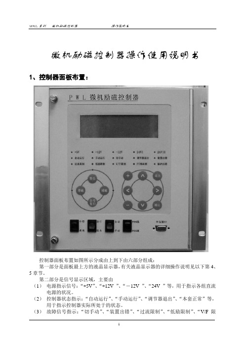
微机励磁控制器操作使用说明书1、控制器面板布置:控制器面板布置如图所示分成由上到下由六部分组成:第一部分是面板最上方的液晶显示器,有关液晶显示器的详细操作说明见以下第4、5章节。
第二部分是信号显示区域,主要由(1)电源指示信号:“+5V”、“+12V ”、“-12V ”、“24V ”等,用于指示各组直流电源的状况。
(2)控制器状态指示:“自动运行”、“手动运行”、“调节器退出”、“本套正常”等,用于指示控制器实际所处于的状态。
(3)故障信号指示:“切手动”、“装置出错”、“过流限制”、“低励限制”、“V/F限制”、“PT熔丝断”、“脉冲出错”等信号,用于指示控制器的故障所在。
其中除“装置出错”外,其余信号皆具有程序自保持功能,即当故障消失后,这些信号不会自动复归,必须人为复归。
“装置出错”是用于指示控制器本身出错的故障信号。
第三部分是控制器操作按钮及指示灯:“置位”按钮、“增磁”按钮、“减磁”按钮及其信号指示,和“信号复归”按钮。
第四部分是液晶显示器键盘操作按钮:包括“∧”键、“∨”键、“<”键、“>”键、“+”键、“-”键、“退出”键、“确认”键。
其中“∧”键、“∨”键用于光标上下移动或屏显前翻后翻;“<”键、“>”键用于光标的左移或右移;“+”键、“-”键用在参数修改时数字量的增加或做试验时各种试验选项的选择等等。
第五部分控制器操作开关及指示灯:“中控”/“就地”开关、“运行”/“退出”开关、“自动”/“手动”开关、“PSS投”/“PSS退”开关及相应的指示灯。
第六部分是串行口:用于同后台机或笔记本电脑通讯,将控制器的参数、试验波形、故障记录、事件记录等数据上传至后台机或笔记本电脑,属于即插即用型,可带电插拔。
上图所示为50MW及以上发电机组励磁调节装置微机励磁控制器面板布置图。
针对25MW及以下发电机组励磁调节装置,如果机组加装PSS则对电力系统影响太小,因此控制器面板布置图没有“PSS投退”开关,其余同上图。
工作文档SPPA-T3000用户手册(组态手册3)
sSPPA-T3000,用户手册用户组态手册(共4册,第3分册)目,录1,,模板编辑器.................... 错误!未指定书签。
1.1,,启动模板编辑器 ...... 错误!未指定书签。
1.1.1,,退出模板编辑器.. 错误!未指定书签。
1.2,,常规布置................. 错误!未指定书签。
1.2.1,,工具栏.................. 错误!未指定书签。
1.2.1.1,,标准............... 错误!未指定书签。
1.2.1.2,,链接............... 错误!未指定书签。
1.2.1.3,,排列............... 错误!未指定书签。
1.2.1.4,,图形布局....... 错误!未指定书签。
1.2.1.5,,交互式绘图工具错误!未指定书签。
1.2.2,,模板的上下文菜单错误!未指定书签。
1.2.3,,单一、持久模式.. 错误!未指定书签。
1.2.4,,选项...................... 错误!未指定书签。
1.2.5,,窗口...................... 错误!未指定书签。
1.2.6,,保存视图.............. 错误!未指定书签。
1.3,,模板功能................. 错误!未指定书签。
1.3.1,,保存模板.............. 错误!未指定书签。
1.3.2,,以新的名字保存模板错误!未指定书签。
1.3.3,,打开库.................. 错误!未指定书签。
1.3.4,,编辑模板.............. 错误!未指定书签。
1.3.5,,创建新的模板...... 错误!未指定书签。
1.3.6,,删除模板.............. 错误!未指定书签。
1.3.7,,删除模板库节点.. 错误!未指定书签。
1.3.8,,将模板移动到另一个库节点错误!未指定书签。
佩尔科冷点PRO和PLUS微波水负载和处理表面手册说明书

PELCO ColdSpot® PRO and PLUSMicrowave Water Load and Processing SurfaceProduct No. 36116-10 PVC with Glass Surface and 36116-20 PolypropyleneThe PELCO ColdSpot® serves as the water load and processing surface for your tissue samples, slides, slide staining container or other processing protocols.Features•Provides a processing surface with an even, controllable temperature that eliminates hot spots/cold spots •Dampens the standing wave patterns generated by the closed cavity design of microwave ovens •Simplifies the operation of microwave processing by omitting the need for most microwave calibration •Offers speed, control and simplicity, a true revolution in microwave processing•Rests on the floor of any model PELCO® Microwave System, connecting to the PELCO® Load Cooler or PELCO® SteadyTemp™ Pro•Holds cooled water which is continuously circulated between the PELCO ColdSpot® and the Load Cooler or PELCO® SteadyTemp™ Pro•The 36116-10 with its glass surface is designed for use with the PELCO® EM Pro Microwave Vacuum Chamber (Product No. 3536).The glass surface can be used as the base for PELCO® Microwave Vacuum Chamber to allow processing of samples directly on the water-cooled surface while under vacuum. •Can be used with the Sequenza™ Slide Rack (Product No. 36105). Each rack holds ten slides at a time during microwave-assisted staining protocols.Installation and Operation of the PELCO ColdSpot® with a Load Cooler.1.Install the hoses.With the PELCO ColdSpot® outside the microwave, route the red stripped silicone hosethrough the hole in the lid and connect to the fitting inside the reservoir. Connect the translucent hose to the fitting on the side of the reservoir. Set the ColdSpot® on a flat surface. Fill with water until the water level covers the side connection’s inlet inside the reservoir. When the unit is filled outside the microwave any spills can be easily dried off prior to placement in the microwave. NOTE: Remove as many bubbles as possible under the top surface by lifting the reservoir end of the PELCO ColdSpot® and gently tapping the other end on the counter.2.Insure that the Load Cooler is primed by following the instructions in the microwave manual.3.Connect the two silicon rubber hoses that are supplied with the unit to the “Load-In” and “Load-Out”ports on the inside upper left rear of the microwave cavity. The red stripped hose should be attached to the “Load-Out” port.a.For older microwave models the Quick Disconnect fittings will have to be removed from thehoses.4.Turn on the load cooler. Lift the end where the hoses are attached to remove any trapped air from underthe top surface.5.At the end of operation for the day or when the Load Cooler is turned off, disconnect the ColdSpot toprevent overflowing. On the PELCO BioWave® Pro unplugging the Quick Disconnect fittings will stop any flow and plug the ports. For older microwave models place a 600ml or larger beaker containing36116-10, -20 TN V3 08262011 Page 1 of 536116-10, -20 TN V3 08262011 Page 2 of 5 approximately 250ml of water on the PELCO ColdSpot ®. Then disconnect the hoses from the PELCO ColdSpot ® fittings and place the disconnected ends of the hoses in the beaker. 6. To resume operation repeat steps 2-4. Check the water level. The water should cover the inlet to the outside connector.WARNINGS • Check the water level in the reservoir with the load cooler running to ensure the correct volume of water is in the unit prior to beginning a microwave protocol. • If Step 5 of the operation instructions is not done at the end of the day or when the Load Cooler is turned off, water will drain back from the system and may cause the PELCO ColdSpot ® to overflow into the microwave cavity. • The PELCO ColdSpot ® should never be used without running the Load Cooler. The maximum service temperature for the water inside the 36116-10 PRO unit is 60°C and inside the 36116-20 PLUS unit is 90°C. This temperature will not be reached or exceeded with a properly operating Load Cooler. PELCO ColdSpot ® with the load ports configured for use with the Load Cooler Patent #6329645 Installation and Operation of the PELCO ColdSpot ® with a PELCO ® SteadyTemp Pro.• If the PELCO SteadyTemp TM Pro is connected to the PELCO BioWave ® Pro, The Red striped hose from the PELCO SteadyTemp TM Pro is connected to the “B -RED STRIPE” fitting and the clear hose is connected to the “A -OPAQUE” fitting at the back of the microwave. The setup will look like Fig 2.o For the 34700 models if the SteadyTemp™ Pro is not connected to the BioWave™, unhook the load cooler tubing lines from the port on the rear of the microwave in order to attach the SteadyTemp™ Pro tubing lines. (The Quick Disconnect fittings will have to be removed from the hoses.) The plastic hose clamps can be removed by pushing or prying the two ends in opposite direction to disengage the teeth. Drain the tubes into a beaker while running the loadFigure 1cooler. Fold each end of these tubes and crimp with the hose clamp. The Red stripped hosefrom the SteadyTemp™ Pro is then clamped to the top "Load Out" port and the clear hose isclamped to the lower “Load In” port. The middle port is not used.1.Install the hoses. With the PELCO ColdSpot® outside the microwave, connect the translucent siliconhose to the fitting on the side of the reservoir, and the red stripe hose to the fitting inside the reservoir.Fill with water until the water level is at the halfway point in the rear reservoir. When the unit is filled outside the microwave any spills can be easily dried off prior to placement in the microwave. Thehalfway point is determined when the unit is sitting flat on a counter.NOTE: Remove as many bubbles as possible under the top surface by lifting the reservoir end of the PELCO ColdSpot® and gently tapping the other end on the counter.2.On the PELCO BioWave® Pro model, connect the translucent silicone tube to the “IN -OPAQUE” upperfront fitting on the left side of the microwave cavity and red silicone tube to the “OUT –RED STRIPED”lower front fitting on the left side of the microwave cavity. The translucent tube should then be connected to the left outside fitting of the PELCO ColdSpot®. The upper left fitting delivers water to the top of the PELCO ColdSpot® reservoir. The setup will look like Fig 3.a.For some of the PELCO BioWave® Pro and older microwave models the Quick Disconnect fittingswill have to be removed from the hoses.b.For 34700 and older, connect the two silicon rubber hoses that are supplied with the unit to the“Load-In” and “Load-Out” ports on the inside upper left rear of the microwave cavity. The redstripped hose should be attached to the “Load-Out” port.3.Press the I/O button on the SteadyTemp™ Pro to turn it on. This will start circulation of the water intothe PELCO ColdSpot®.4.Add fluid to the PELCO ColdSpot® Pro reservoir as necessary to maintain the water level.5.Set and adjust the temperature as instructed in the PELCO SteadyTemp TM Pro manual and allow thewater to reach that temperature. The maximum operation temperature of the PELCO ColdSpot® Pro is 60°C. The PELCO® SteadyTemp™ Pro set point should be below 55°C in order to remain below 60°C during microwave processing. The temperature probe can be placed in the Temperature Probe Port of the PELCO ColdSpot® and the temperature restriction set at or below 60°C to protect the PELCO ColdSpot®Pro from overheating.a.The maximum operation temperature of the PELCO ColdSpot® Plus is 90°C.WARNINGS• The Load Cooler controls should not be used. Do not run the Load Cooler without water in it as this will damage the pump. The user has to make sure the SteadyTemp™ Pro is on when operating the BioWave™ Pro with the PELCO ColdSpot® Pro.The PELCO ColdSpot® Pro should never be used without running the SteadyTemp™ Pro. The maximum service temperature for the water inside the PELCO ColdSpot® Pro unit is 60°C. The microwave temperature restriction should be set at or below this temperature.36116-10, -20 TN V3 08262011 Page 3 of 5Figure 2Model 36500 PELCO BioWave® with the PELCO SteadyTemp TM Pro36116-10, -20 TN V3 08262011 Page 4 of 536116-10, -20 TN V3 08262011 Page 5 of 5Figure 3 PELCO ColdSpot ® with the load port configured for use with the PELCO SteadyTemp Pro. Patent No. 6329645。
源配电板_K-PW 系列电源配电板使用说明书
HOLLiAS MACS -K系列模块2014年5月B版HOLLiAS MAC-K系列手册- K-PW系列电源配电板使用说明书重要信息危险图标:表示存在风险,可能会导致人身伤害或设备损坏件。
警告图标:表示存在风险,可能会导致安全隐患。
提示图标:表示操作建议,例如,如何设定你的工程或者如何使用特定的功能。
目录1.概述 (1)2.K-PW01 交流电源配电板 (2)2.1连接器定义 (2)2.2外形尺寸 (3)3.K-PW11 直流电源配电板 (4)3.1连接器定义 (4)3.2外形尺寸 (7)4.K-PW21 查询电源分配板 (8)4.1连接器定义 (8)4.2指示灯 (9)4.3外形尺寸 (9)5.技术指标 (10)5.1K-PW01 (10)5.2K-PW11 (10)5.3K-PW21 (11)K-PW系列电源配电板1.概述K-PW系列电源分配板有三个型号,分别是K-PW01、K-PW11和K-PW21。
K-PW01是交流电源配电板,K-PW11是直流电源配电板,安装在机柜背面,配合AC/DC电源模块,为整个K系列硬件提供系统电源、现场电源。
K-PW21是查询电源分配板,安装在机柜正面,为I/O模块提供24V/48VDC查询电源。
下面将分别介绍。
2.K-PW01 交流电源配电板K-PW01是K系列硬件交流分配板,实现交流电源的分配输出功能,给系统电源、现场电源、辅助电源的AC/DC电源模块提供输入配电。
有两路110V/220V交流电输入,每路输入交流电源平分成5路输出。
两组通道各带有一个PCB安装滤波器,用来给系统电源和现场电源AC/DC供电。
每路带独立的船型开关,可以接通或关断本路,开关上自带通断指示灯。
船型开关在切断对应通道电源时,该指示灯熄灭;接通对应通道电源时,该指示灯亮。
K-PW01交流配电板安装在35mm宽的标准DIN导轨上,与导轨采用卡扣的固定方式,其外观示意图如图2-1所示。
派珀飞机客户服务手册说明书
761-640 PA-32RT-300 & -300T Lance II & Turbo Lance II 753-816 PA-34-200 Seneca 761-589 PA-34-200T Seneca II761-750 PA-34-220T Seneca III & Seneca IV (IV S/N’s 3448038 thru 3448079)761-887 PA-34-220T Seneca IV & V (IV S/N’s 3447001 thru 3447029; V S/N’s 3449001 & up)761-470 PA-36 Pawnee Brave761-659 PA-38 Tomahawk & Tomahawk II 761-717 PA-42 & -42-720 Cheyenne III & IIIA761-818 PA-42-720 Cheyenne IIIA (Advanced Trainer)761-792 PA-42-1000 Cheyenne 400761-842 PA-42-1000 Cheyenne 400 (Advanced Trainer) Supplement 761-663 PA-44-180 & -180T Seminole and Turbo Seminole (44-180 ending S/N 4495013)761-891 PA-44-180 Seminole (S/N’s 4496001 & up)761-782 PA-46-310P/350P Malibu / Malibu Mirage (350P ending S/N 4622200)761-878 PA-46-350P Malibu Mirage (S/N’s 4636001 & up) 766-884 PA-46-350P Malibu Mirage (G1000) / M350767-004 PA-46-500TP Malibu Meridian (Meggit / Avidyne)766-882 PA-46-500TP Malibu Meridian (G1000) / M500767-616 PA-46-600TP M600767-069 PA-46R-350T Malibu Matrix766-885PA-46R-350T Malibu Matrix (G1000)761-471 PA-36 Pawnee Brave761-660 PA-38 Tomahawk & Tomahawk II761-523 PA-42 & -42-720 Cheyenne III & IIIA761-852 PA-42-720 Cheyenne IIIA (Advanced Trainer)761-789 PA-42-1000 Cheyenne 400761-840 PA-42-1000 Cheyenne 400 (Advanced Trainer) Supplement761-664 PA-44-180 & -180T Seminole & Turbo Seminole(44-180 ending S/N 4495013)761-892 PA-44-180 Seminole (S/N’s 4496001 & up)761-783 PA-46-310P/350P Malibu / Malibu Mirage (350P ending S/N 4622200)761-876 PA-46-350P/46R-350T Malibu Mirage / M350 / Malibu Matrix(350P S/N’s 4636001 & up)767-005 PA-46-500TP Malibu Meridian (Meggitt / Avidyne)767-072 PA-46-500TP Malibu Meridian (G1000) / M500767-617 PA-46-600TP M600(1) See page 35 in the Customer Service Information File (P/N 1753-755), for a list of current revision datesfor Piper Flight Manuals.753-772 PA-23-250 (Six Place) Aztec “D” (1968–1969)753-775 PA-23-250 (Six Place) AiResearch Turbo Aztec “D” (1968–1969)753-794 PA-23-250 (Six Place) Lycoming Turbo Aztec “D” (1969)752-467 PA-24-180, PA-24-250 (1958)753-529 PA-24-180, PA-24-250 (1959–1960)753-570 PA-24-180, PA-24-250 (1961)753-597 PA-24-180, PA-24-250 (1962–1964)(See also 753-629 on page 18.)753-685 PA-24-260 (1965)753-696 PA-24-260 “B” (1966–1969)753-774 PA-24-260 “C” (1969–1972)753-823 PA-24-260 Turbo (1970–1972)753-598 PA-24-400 (1964–1965)753-584 PA-28-140 (1964–1968)753-787 PA-28-140 “B” (1968–1969)753-805 PA-28-140 “C” (1970)761-459 PA-28-140 “D” (1971 )761-489 PA-28-140 “E” (1972)761-512 PA-28-140 (1973)753-600 PA-28-150,-160,-180 “B” (thru 1964)753-683 PA-28-150,-160,-180 “C” (1965–1967)753-765 PA-28-180 “D” (1968–1969)753-806 PA-28-180 “E” (1970)761-460 PA-28-180 “F” (1971)761-490 PA-28-180 “G” (1972)761-513 PA-28-180 (1973)753-648 PA-28-235 (1963–1965)753-729 PA-28-235 “B” (1966–1967)753-767 PA-28-235 “C” (1968–1969)753-808 PA-28-235 “D” (1970)761-463 PA-28-235 “E” (1971)761-491 PA-28-235 “F” (1972)761-514 PA-28-235 (1973)753-750 PA-28R-180 (1967–1969)753-811 PA-28R-180 (1970)761-461 PA-28R-180 “B” (1971)753-795 PA-28R-200 (1969)753-807 PA-28R-200 (1970)761-462PA-28R-200 “B” (1971)753-644 PA-30 (1963–1965)753-697 PA-30 “B” (1965–1968)761-452 PA-30 “B” Turbo (1965–1968)753-773 PA-30 “C” (1968–1969)753-778 PA-30 Turbo “C” (1968–1969)753-780 NLA PA-31-300 (1968–1969)753-688 PA-32-260 (1965–1968)753-788 PA-32-260 “B” ( 1969)753-809 PA-32-260 “C” (1970)761-464 PA-32-260 “D” (1971)761-494 PA-32-260 “E” (1972)761-515 PA-32-260 (1973)753-745 PA-32-300 (1966–1968) (S/N’s 32-40001 thru 32-40545)753-789 PA-32-300 “B” (1969) (S/N’s 32-40566 thru 32-40777)753-810 PA-32-300 “C” (1970)761-465 PA-32-300 “D” (1971)761-495 PA-32-300 “E” (1972)761-516PA-32-300 (1973)761-827 PA-28R-201 Arrow, (1988–1994) (S/N’s 2837001–2837061)761-869 PA-28R-201 Arrow, (1995 & up) (S/N’s 2844001 & up)761-636 PA-28R-201T Cherokee Turbo Arrow III (1977–1978)761-833 PA-28R-201T Turbo Arrow (1989 & up) (S/N’s 2803001 & up)761-690 PA-28RT-201 Arrow IV (1979)761-730 PA-28RT-201 Arrow IV (1980 & up)761-691 PA-28RT-201T Turbo Arrow IV (1979 & up)761-456 PA-31 Navajo (S/N’s 1–659 & 661–711)761-472 PA-31 Navajo without Wing Locker (S/N’s 712–751)761-483 PA-31 Navajo with Wing Locker (S/N’s 660 & 712–751)761-501 PA-31 Navajo (S/N’s 752 thru 7612110)761-626 PA-31 Navajo (1977–1979)761-723 PA-31 Navajo (1980 & up)761-571 PA-31-325 Navajo C/R (1974–1976)761-627 PA-31-325 Navajo C/R (1977–1979)761-724 PA-31-325 Navajo C/R (1980 & up)761-486 PA-31-350 Navajo Chieftain (1973–1976)761-628 PA-31-350 Chieftain (1977–1979)761-725 PA-31-350 Chieftain (1980 & up)761-772 PA-31-350 T-1020753-768 PA-31P Pressurized Navajo (1970–1976)761-629 PA-31P Pressurized Navajo (1977)761-795 PA-31P-350 Mojave761-560 PA-31T Cheyenne (1974–1976)761-625 PA-31T Cheyenne and Cheyenne II (1977–1979)761-703 PA-31T Cheyenne II (1980–1983)761-673 PA-31T1 Cheyenne I (1978–1983)761-796 PA-31T1 Cheyenne IA761-762 PA-31T2 Cheyenne II XL (1981 & up)761-777 PA-31T3 T-1040761-558 PA-32-260 Cherokee Six-260 (1974–1976)761-631 PA-32-260 Cherokee Six-260 (1977–1978)761-559 PA-32-300 Cherokee Six-300 (1974–1976)761-632 PA-32-300 Cherokee Six-300 (1977–1979)761-616 PA-32R-300 Cherokee Lance (1976)761-633 PA-32R-300 Cherokee Lance (1977–1978)761-637 PA-32RT-300 Lance II (1978–1979)761-657 PA-32RT-300T Turbo Lance II (1978–1979)761-728 PA-32-301 Saratoga (1980 & up)767-031 PA-32-301FT Piper 6X767-059PA-32-301FT Piper 6X (with Garmin G1000 EFIS)761-729 PA-32-301T Turbo Saratoga (1980 & up)767-032 PA-32-301XTC Piper 6XT761-727 PA-32R-301 Saratoga SP (1980–1993)761-856 PA-32R-301 Saratoga II HP (1993–1995) (S/N’s 3213042–3213103)761-871 PA-32R-301 Saratoga II HP (1995) (S/N’s 3246001–3246017)761-885 PA-32R-301 Saratoga II HP (1996–1997) (S/N’s 3246018–3246087)761-899 PA-32R-301 Saratoga II HP (1997–2006) (S/N’s 3246088–3246244)761-726 PA-32R-301T Turbo Saratoga SP (1980 & up)761-900 PA-32R-301T Saratoga II TC (1997–2008) (S/N’s 3257001–3257446,3257475, 3257448–3257454,3257460,3257487)and3257485,3257480,767-058 PA-32R-301T Saratoga II TC (G1000) (2007–2008)(S/N’s3257455–3257493)3257447,753-815 PA-34-200 Seneca (S/N’s 34-7250001 thru 34-7250214)761-506 PA-34-200 Seneca(S/N’s 34-7250001 thru 34-7250189 when Piper Kit 760-607 is installed;S/N’s 34-7250190 thru 34-7250214 when Piper Kit 760-611 is installed; andS/N’s 34-7250215 thru 34-7350353)761-577 PA-34-200 Seneca (1974)761-593 PA-34-200T Seneca II (1975–1976)761-634 PA-34-200T Seneca II (1977–1981)761-756 PA-34-220T Seneca III (1981 & up)761-844 PA-34-220T Seneca III (1989–1994) (S/N’s 3448001–3448035 (28 Volt))761-854 PA-34-220T Seneca IV (1994–1995) (S/N’s 3448038–3448079 (28 Volt))761-872 PA-34-220T Seneca IV (1995–1996) (S/N’s 3447001–3447029)761-890 PA-34-220T Seneca V (1997–2006) (S/N’s 3449001–3449325;less 3449311 and 3449323)767-046 PA-34-220T Seneca V (Avidyne) (2006–2010) (S/N’s 3449311, 3449323;3449326– 3449409, 3449411–3449414, & 3449420)767-089 PA-34-220T Seneca V (G600) (2010–2012)(S/N’s 3449410, 3449415–3449419, 3449421–3449466) 767-092 PA-34-220T Seneca V (G1000) (2013–2017) (S/N’s 3449459, 3449467 & up) 767-105 PA-34-220T Seneca V (G1000 NXi) (2018 & up) (S/N’s 3449509 and up)761-614 PA-36-285 Pawnee Brave (1975–1978)761-648 PA-36-300 Pawnee Brave 300 (1977–1981)761-674 PA-36-375 Brave 375 (1979 & up)761-658 PA-38-112 Tomahawk (1978 & up)761-453 PA-39 Turbo and PA-39 (1970–1972)761-521 PA-42 Cheyenne III761-793 PA-42-720 Cheyenne IIIA761-791 PA-42-1000 Cheyenne 400761-662 PA-44-180 Seminole (1979–1982)761-841 PA-44-180 Seminole (1989–1993) (S/N’s 4495001–4495013)761-873 PA-44-180 Seminole (1995 & up) (S/N’s 4496001 & up; less 4496174) (includes G500-equipped airplanes)767-049 PA-44-180 Seminole (Avidyne) (2006–2010)(S/N’s 4496174; 4496224–4496226, 4496230–4496250, 4496253,4496257, 4496258, 4496261, and 4496265–4496283)767-090 PA-44-180 Seminole (G1000) (2013–2017)(S/N’s 4496331, 4496339–4496394 , 4496396, 4496401–4496402,and 4496409–4496411.)767-101 PA-44-180 Seminole (G1000 NXi) (2016 & up)(S/N’s 4496395, 4496397 & up)761-748 PA-44-180T Turbo Seminole (1980 & up)761-784 PA-46-310P Malibu (1984–1986) (S/N’s 46-8408001 thru 4608007)761-816 PA-46-310P Malibu (1986–1988) (S/N’s 4608008–4608140)761-825 PA-46-350P Malibu Mirage (1989–1995) (S/N’s 4622001–4622200)761-866 PA-46-350P Malibu Mirage (1995) (S/N’s 4636001–4636020)761-884 PA-46-350P Malibu Mirage (1996–1997) (S/N’s 4636021–4636131)767-003 PA-46-350P Malibu Mirage (1998–1999) (S/N’s 4636132–4636195)767-007 PA-46-350P Malibu Mirage (1999–2005) (S/N’s 4636196–4636374)767-050 PA-46-350P Malibu Mirage (Avidyne Entegra) (2006–2009)(S/N’s 4636375–4636459, 4636461–4636462, and 4636481)767-082 PA-46-350P Malibu Mirage (G1000) (2010–2015)(S/N’s 4636460, 4636463–4636651, less 4636481, 4636633) 767-096 PA-46-350P M350 (2015–2017)(S/N’s 4636633, 4636652–4636715, 4636717–4636719) 767-102 PA-46-350P M350 NXi (2017 & up) (S/N’s 4636716, 4636720 & up)767-010 PA-46-500TP Malibu Meridian (2000–2003) (S/N’s 4697001–4697156)767-033 PA-46-500TP Malibu Meridian (2000–2003) (S/N’s 4697001–4697156 when Piper Kits No. 767-360 and767-361 are installed); and(2003) (S/N’s 4697157–4697173)767-043 PA-46-500TP Malibu Meridian (2004–2005) (S/N’s 4697174–4697215, less 4697198)767-045 PA-46-500TP Malibu Meridian (Avidyne Entegra) (2006–2009)(S/N’s 4697198, 4697216–4697398, less 4697340) 767-070 PA-46-500TP Malibu Meridian (G1000) (2009–2015)(S/N’s 4697340, 4697399–4697581 less 4697549 and 4697569) 767-095 PA-46-500TP M500 (2015–2017)(S/N’s 4697549, 4697569, 4697582–4697625, 4697627–4697630) 767-103 PA-46-500TP M500 NXi (2017 & up) (S/N’s 4697626, 4697631 & up)767-098 PA-46-600TP M600 (2016–2018)(S/N’s 4698001–4698060, 4698062–4698080)767-106 PA-46-600TP M600 G3000 NG (2018 & up) (S/N’s 4698061, 4698081 & up)767-067 PA-46R-350T Malibu Matrix (Avidyne Entegra) (2008–2009) (S/N’s 4692001–4692133, 4692141, 4692149 and 4692153)767-083PA-46R-350T Malibu Matrix (G1000) (2010 & up) (S/N’s 4692134 & up)Avionics Service Manuals761-467 Piper Avionics Equipment - Installation, Service, and Parts Manualincludes: PTR-1 VHF TransceiverO-1 and OL-1 OMNI Converter;PRC-3 Radio Compass;PRC-4 Radio Compass; and,PM-1 Marker BeaconAvionics Wiring Diagram Service ManualsNote: Wiring diagrams for models / model years not listed here typically appear in the appropriate airplane maintenance / service manual.761-684 Avionics Wiring Diagram Service Manual PA-23-250 (6), Complete (1978) PA-31 Series and PA-31T 761-685 Avionics Wiring Diagram Service Manual PA-28/32/34 Series Complete (1978)761-682 Avionics Wiring Diagram Service Manual All Models prior to 1975 761-643 NLA Avionics Wiring Diagram Service Manual PA-23-250 (6), Complete (1975-1976) PA-31 Series,(P/N’s 761-646 & 761-647 Combined) PA-31P and PA-31T 761-646 Avionics Wiring Diagram Service Manual PA-23-250 (6) and Volume I only (1975-1976) PA-31 Series 761-647 Avionics Wiring Diagram Service Manual PA-31P and PA-31T Volume II only (1975-1976)761-645 NLA Avionics Wiring Diagram Service Manual PA-28/32/34 Series Complete (1975-1977)761-671 Avionics Wiring Diagram Service Manual PA-23-250 (6), Complete (1977) PA-31 Seriesand PA-31T 761-713 Avionics Wiring Diagram Service Manual PA-28/32/34 & 44 Series Complete (1979)761-520PA-31T and PA-31T1 Cheyenne - 50 Hr.761-644PA-31T and PA-31T1 Cheyenne - 100 Hr.761-758PA-31T2 Cheyenne II XL - 100 Hr.761-774PA-31T3 T-1040 - 100 Hr.767-019PA-32-260/300 Cherokee Six - 50 Hr.761-747PA-32-301/301T Saratoga and Turbo Saratoga - 50 Hr.767-027PA-32-301FT Piper 6X - 50 Hr.767-028PA-32-301XTC Piper 6XT - 50 Hr.767-018PA-32R-300 Cherokee Lance - 50 Hr.761-017PA-32R-301/301T Saratoga SP, Turbo Saratoga SP,Saratoga II HP - 50 Hr. (II HP ending S/N 3213103)767-016PA-32R-301 Saratoga II HP - 50 Hr. (S/N’s 3246001 & up)767-015PA-32R-301T Saratoga II TC - 50 Hr.761-737PA-32RT-300/300T Lance II / Turbo Lance II - 50 Hr.761-499PA-34-200 Seneca - 50 Hr.761-592PA-34-200T Seneca II - 50 Hr.761-753PA-34-220T Seneca III and IV - 50 Hr. (IV S/N’s 3448038 thru 3448079)767-006PA-34-220T Seneca IV and V - 50 Hr. (IV S/N’s 3447001 thru 3447029)761-661PA-38-112 Tomahawk - 50 Hr.761-760PA-42 and PA-42-720 Cheyenne - 50 Hr.761-739PA-42 and PA-42-720 Cheyenne - 100 Hr.761-820PA-42-720 Cheyenne (Advanced Trainer) - 50 Hr.761-819PA-42-720 Cheyenne (Advanced Trainer) - 100 Hr.761-851PA-42-1000 Cheyenne 400 - 50 Hr.761-790PA-42-1000 Cheyenne 400 - 100 Hr.761-845PA-42-1000 Cheyenne 400 (Advanced Trainer) - 50 Hr.761-846PA-42-1000 Cheyenne 400 (Advanced Trainer) - 100 Hr.761-733PA-44-180/180T Seminole / Turbo Seminole - 50 Hr.(180 ending S/N 4495013)767-014PA-44-180 Seminole (S/N’s 4496001 & up) - 50 Hr.761-788PA-46-310P/350P Malibu / Malibu Mirage - 50 Hr.(350P ending S/N 4622200)767-013PA-46-350P/46R-350T Malibu Mirage / M350 / Malibu Matrix - 50 Hr.(350P S/N’s 4636001 & up)767-009PA-46-500TP Malibu Meridian (Meggitt / Avidyne) - 100 Hr.767-073PA-46-500TP Malibu Meridian (G1000) / M500 - 100 Hr.767-624PA-46-600TP M600 - 100 Hr.THIS PAGE INTENTIONALLY BLANK230-212 PA-31P Pressurized Navajo230-1088 PA-31P-350 Mojave230-210 PA-32-260, -300 Cherokee Six230-1046 PA-32-301/301T Saratoga766-857 PA-32-301FT Piper 6X766-858 PA-32-301XTC Piper 6XT230-916 PA-32R-300 Lance230-1045 PA-32R-301/301T Saratoga SP and Saratoga II HP230-1047 PA-32R-301 Saratoga II HP (S/N’s 3246001 & up)230-2047 PA-32R-301T Saratoga II TC (S/N’s 3257001 & up)230-953 PA-32RT-300/300T Lance II230-208 PA-34-200 Seneca230-856 PA-34-200T Seneca II230-1061 PA-34-220T Seneca III and IV (IV S/N’s 3448038 thru 3448079)767-012 PA-34-220T Seneca IV and V (IV S/N’s 3447001 thru 3447029)230-783 PA-36-285, -300, -375 Pawnee Brave230-960 PA-38-112 Tomahawk230-963 PA-44-180 and PA-44-180T Seminole (44-180 ending S/N 4495013) 230-1963 PA-44-180 Seminole (S/N’s 4496001 & up)230-1085 PA-46-310P/350P Malibu (350P ending S/N 4622200)767-011 PA-46-350P/46R-350T Malibu Mirage / Malibu Matrix(350P S/N’s 4636001 & up)See our website () for a current list of authorized Piper:Dealers,Sales Centers,andService Centers。
kppw客客威客开发手册
类务业统系 cni/bil/ 类具工统系 repleh/bil/ 包言语文中 nc/gnal/ 易网�讯腾�浪新�端户客列系博微 obiew/tneilc_ekek/ 端户客 retnecu retnecu/tneilc_ekek/ 端户客 ipa 淘 ipaoat/tneilc_ekek/ 端户客信短 sms/tneilc_ekek/ 录目端户客 dniwphp tneilc_wp/tneilc_ekek/ 录目端户客 ekek ekek/tneilc_ekek/ 口入转跳台后 ekek/ 页首件文装安 php.xedni/llatsni/ 件文板模的/ 录目放存片图务服值增统系 sloot/sys/sdaolpu/atad/ 录目放存片图级等户用统系 kram/sys/sdaolpu/atad/ 录目放存片图证认统系 htua/sys/sdaolpu/atad/ 录目放存片图告广统系 da/sys/sdaolpu/atad/ 放存夹件文为日月年以件文传上通普 sdaolpu/atad/ 件文的成生类板模由,件文标目的行运 php c_lpt/atad/ 录目时临的传上象图户用 pmt/atad/ 录目件文话会统系 noisses/atad/ 录目存缓 etilqs,存缓件文 ehcac_atad/atad/ 录目份备库据数�份备板模统系 pukcab/atad/ 片图象图户用统系 ratava/atad/ 片图位告广统系 cipda/atad/ 件文层制控心中户用 resu/lortnoc/ 铺店人个�铺店业企�层制控间空铺店 ecaps/lortnoc/ 藏稳件稿�顶置务任�急加务任�证模项费附统系 me tiyap/lortnoc/ 件文层制控讯资统系 elcitra/lortnoc/ 件文层制控 xaja 统系 xaja/lortnoc 件文层示显台后统系 lpt/nimda/lirtnoc/ 件文层制控台后统系 nimda/lortnoc/ 件文层制控用应 lortnoc/ 件文置配端户客 retnecU php.retnecu.gifnoc/gifnoc/ 件文置配端户客 dniwPHP php.wp_gifnoc/gifnoc/ 件文置配化始初统系 i.gifnoc/gifnoc/ 类理处作操库据数 esab/ 证认名实�机手�业企�件邮�行银有,证模证认统系 htua/ 口入件文收接端户客 dniwphP php.ipa_wp/iap_wp/ipa/ 件文收接端户客 retnecu php.cu/ipa/ 明说件文 件文录目
价值与技术 KPP SOFT 工具软件 入门手册说明书
Value & TechnologyKPP SOFT工具软件入门手册[第二版修订1]目录第一章Windows下KPP的安装 (1)1-1.软件对计算机系统要求 (1)1-2.软件安装 (1)1-3.软件启动 (5)第二章编程环境 (6)2-1.选项子菜单 (6)2-2.自定义子菜单 (10)2-3.用户权限管理子菜单 (11)2-4.环境子菜单 (12)2-5.增大编程区空间 (13)第三章程序编辑 (15)3-1.新建工程 (15)3-2.输入梯形图 (16)3-3.编辑梯形图 (20)3-4.检索 (20)3-5.图标 (22)3-6.下载工程 (23)3-7.PLC设定 (26)3-8.导入导出工程 (30)3-9.程序比较 (31)第四章文档编辑 (33)4-1.文档显示与否设置 (33)4-2.变量名、接线信息及功能存储器注释的输入 (34)4-3.回路注释输入 (35)4-4.级行注释输入 (35)第五章其他视图 (36)5-1.语句视图 (36)5-2.级视图 (36)5-3.交叉引用视图 (38)5-4.PID视图 (39)第六章监控与调试 (47)6-1.监控梯形图 (47)6-2.页监视 (48)6-3.数据视图 (49)6-4.设置断点 (50)6-5.调试工具 (50)6-6.离线模拟 (53)修订履历注:由于产品更新和改进,所使用软件的实际内容可能会与本手册资料的说明有所不同,不周之处敬请谅解。
我们会根据产品、软件更新和改进的情况,不断修订本手册资料的内容。
第一章 Windows 下KPP 的安装1-1. 软件对计算机系统要求本软件是WINDOWS 环境下的PLC 编程软件。
利用本软件可以进行程序设计、编写注释说明文档和维护控制应用系统。
注:Windows 8及以上版本安装时,会弹出“Windows Smart Screen ”的警告信息,请继续安装。
点击“Detail Information ”,在画面转换后,点击“Execute ”。
- 1、下载文档前请自行甄别文档内容的完整性,平台不提供额外的编辑、内容补充、找答案等附加服务。
- 2、"仅部分预览"的文档,不可在线预览部分如存在完整性等问题,可反馈申请退款(可完整预览的文档不适用该条件!)。
- 3、如文档侵犯您的权益,请联系客服反馈,我们会尽快为您处理(人工客服工作时间:9:00-18:30)。
一.安装前的准备1. 下载合适的程序包到本地,下载解压缩之后如下图所示:1.2程序包地址为:/bbs/viewthread.php?tid=669&extra=page%3D12、二进制上传upload 文件夹里的所有程序文件到服务器,如下图所示:注:虚拟主机上传文件请一定使用二进制方式上传,独立主机直接在服务器上下载解压缩即可。
3、修改文件和目录属性注:如果您的主机为nix 操作系统,请设置如下文件夹权限改为777,Windows 主机设置Internet 来宾帐号可读写的权限。
config config/config.php data data/.* (安装完毕777 取消) 如果你对修改文件属性不太明确,请参考更详细的教程:文件权限修改方法二、开始安装使用URL 安装,应用程序安装地址:输入http://**.com/install /index.php 注意:**.com 是您的KPPW 域名。
安装界面如下图所示:1.接受安装协议,开始安装KPPW。
2.安装环境检测3.按照提示,输入相关域名,数据信息,管理员信息说明:数据库服务器本地地址:一般为您的域名。
数据库用户名:是指有权操作KPPW 数据库的用户。
数据库密码:是指安装KPPW 的数据库密码。
数据库名:是指安装KPPW 的数据库名称。
表名前缀:默认为keke_ ,也可以自定义填写,强烈建议使用默认配置。
虚拟主机用户如果不确定以上数据库信息,请与空间商联系确认;独立主机用户请与MySQL 安装人员联系。
填写完毕,提交进入下一步4.点击下一步,开始自动安装安装成功5.点击任务大厅到前台首页至此,kppw1.2已经成功的安装完毕了。
后台管理地址为http://您的域名/keke/,用户名和密码是安装时设置的用户名和密码。
安装过程也可以参考/bbs/viewthread.php?tid=23&extra=page%3D1。
管理首页–系统登录管理首页为完成本系统的基本设置和系统配置信息,左侧提供了常用设置的菜单选项,主要包括基本配置,提现审核,用户管理,文章管理,缓存更新,模板管理,友情链接管理广告管理8个子菜单,方便管理,如下如图:站长统计:统计当前任务总数,悬赏总金额,进行中的任务,注册用户,vip和团队个数。
备忘录:管理员可以记录网站管理相关事情重要公告:显示最近系统更新公告授权信息:显示系统的版本及授权信息2.系统配置设置系统的基本信息,系统邮件和支付接口配置,模型管理,客服和工作室管理,自定义导航和用户体系的相关设置,具体如下:2.1站点信息设置网站标题,logo,公司地址,第三方统计代码,备案号等网站基本信息。
以上信息中,公司logo显示在页面的左上角,除最后一项外,都显示在网页的底部联系方式上,如下图:网站是否关闭:默认为开启状态,设为关闭后将不能访问。
关闭后,访问网站有如下提示:2.1.2基本配置伪静态,代金券的开启与关闭,seo设置,文件上传,非法关键字设置。
1).开启或关闭伪静态:设为开启时,如下图所示。
更多伪静态信息参考/bbs/viewthread.php?tid=1092).代金券是否启用:默认为开启状态。
设为开启时,将现金兑换成代金券,可以使用代金券进行交易。
如图显示的是会员的现金和代金券数。
如果关闭,我的账号中只有现金数量,所有交易都通过现金进行。
3).网站标题,显示在网页的标题中4).Meta Keywords,网站关键词信息5).Meta Description,网站描述6).附件上限,设置系统上传附件的大小,当超过指定大小时不能上传。
7).附件格式,上传的附件格式。
8).用户禁止关键字:用户关键字过滤9).内容禁止关键字:内容关键字过滤10).新用户注册时间限制:新用户注册在指定时间内不能发布或参与任务。
2.1.3邮件配置设置邮件服务器的相关的参数1).邮件服务器:选择采用服务器内置的email服务,或者采用其他的smtp服务。
默认选择其他的服务器。
2).邮件是否加密链接ssl:默认选择是,利于邮件和系统的安全。
3).发送邮件服务器地址:填写发送邮件的服务器地址4).服务器端口:默认为255).邮件发送账号:发送邮件所需的账号,若没有,则留空6).账号密码:7).邮件回复地址:8).测试邮件地址:测试邮件服务器是否设置成功。
2.1.4支付接口配置或编辑支付宝接口基本信息,用户充值,提现设置。
如图显示的是支付接口列表和支付参数配置信息。
1).支付参数设置:设置用户充值和提现金额的最小值,用户当日的体现最高值。
如图设置,一个用户在一天内最多体现1000元。
2).支付接口配置:在接口列表中,点击配置,得到该接口的配置信息,如图3).是否启用:开启或关闭这个接口,默认为开启;财付通商户编号,交易密钥:申请开通的商户编号和密钥。
文子提示:对这个接口的说明。
2.1.5站内短信设置相应的事件发生时,发送邮件或站内信。
如下图设置,当注册完成时,系统发送站内信通知用户注册成功。
收到系统发送的站内信编辑模板:修改站内信或邮件内容的模板。
站内信内容如下:2.1.6任务模型安装,卸载,管理任务模型。
1).禁用开启任务设为禁用,关闭任务模型,如图禁用悬赏任务模型。
前台显示:点击设为启用即可重新启用这个任务模块。
2).安装任务模型:如图,把task_2放在task目录下,打开task2\control\admin\task config.xml 文件,如下图,分别设置任务模型的id,标识,模型名称,模型目录,作者,状态。
输入模板所在的目录task_2,点击安装即可。
如图安装完成3).卸载任务模型:同安装相反的操作,当不需要这个任务模型是,点击,完成卸载。
2.1.7会员整合如果需要整合其他的用户系统,可以安装适当的版本号插件进行整合。
点击添加,设置整合的插件的相关信息,安装即可。
2.1.8客服管理添加,编辑,等管理客服信息1).添加新客服如图,写入要添加的客服的id,单击添加即可。
添加成功后,系统会给添加的客服发送站内信通知。
2).编辑客服点击编辑,打开客服编辑页面,填写好要修改的信息,点击编辑即可,如下图:3).权限设置:,进入权限编辑页面,可以选择会员组或者系统组中的一个权限。
关于权限的更多设置在用户管理中说明。
4).删除客服,点击按钮即可。
2.1.9工作室管理工作室查看,审核,开启和管理。
1).点击查看查看工作室信息.2).审核,点击审核,工作室审核通过,也可以一次选中多个进行批量审核。
3).点击删除,删除工作室信息。
2.1.10导航管理添加,开启,隐藏导航,编辑链接,导航排序操作。
1).添加链接:分别输入一下内容导航名称:我的任务模型链接地址:index.php?do=task list&model id=10 排序方式:8 是否在新窗口打开:否显示模式:全部显示保存配置,结果如下图所示:2).编辑导航,方法同添加一样,打开导航列表,直接进行编辑即可。
如图编辑导航的标题为任务模型,且在首页隐藏,其他页面显示。
修改后的效果如图所示,在首页不显示,在商城页面显示。
修改后index.php页面导航3).点击删除,删除导航。
2.2.1认证项目管理邮箱认证,实名认证,企业认证,银行认证信息。
1).编辑认证项目如图是编辑认证信息。
认证项目名称:如实名认证,身份认证工作周期:认证审核的时间认证费用:认证所需要的费用认证有效期:认证有效期认证大图标:认证所需要上传的大图片认证小图标:认证所需要上传的大图片认证描述:关于认证的几点说明,这个信息在申请认证时显示。
是否开启:默认是开启,开启后会员可以申请认证。
2).点击删除,删除认证项目。
更多认证信息在认证管理中说明。
2.2.2经验值配置1).经验值配置设置会员参加相关的活动后获得的经验值数。
如设置会员评论任务将获得2个经验值,其他的设置与之相同。
2).经验值等级规则:设置不同经验值的用户等级和权限。
如图,经验值在50~200的头衔是书童,如果没有上传图标,则使用默认图标。
权限设置:为不同等级的用户设置不同的权限。
主要包括悬赏任务,招标任务配置权限,添加任务模型的配置权限,店铺权限和工作室权限。
如上图,点击权限配置,设置书生等级的禁用发布悬赏任务。
2.2.3信誉值配置设置信誉值和信誉值规则。
1).设置互评开启时间:中标时:选择该选项时,当威客中标时,威客和雇主开始互评。
公示期:当任务处于公示期是双方才能开始互评。
结束时:当任务结束时双方互评。
后面两项是设置自动评价的时间和评价等级,如上图所示,如果双方在任务结束的时候还没有互评,则系统在任务结束后三天自动评价为好评。
2).增加新规则,点击如图我们新增了一条规则,设置金额在50~100之间,好评,中评将分别获得3.2.1个积分,点击保存配置即可。
1.编辑规则:在规则列表中直接编辑,方法和添加类似,保存配置即可。
2.删除规则,点击即可。
信誉值等级规则:设置信誉值和它对应的卖家和卖家的图标。
编辑信誉值:设置信誉值的范围,上传卖家或买家的图标,如下图,然后单击保存配置即可。
增加新规则:输入金额,分别上传上传卖家,买家在次信誉值的图片,保存配置即可。
删除经验值:在经验值列表中点击即可。
2.2.4.vip收费规则配置vip收费金额和有效期限。
添加,编辑规则,输入金额和有效期限,单击保存编辑即可。
编辑规则同理修改好金额和有效期限,单击保存编辑即可。
删除规则:把光标放在要删除的记录的两个表单中的任意一个中,然后点击即可删除。
3. 文章管理对资讯,帮助,单页三个模块的信息进行添加,修改和编辑操作。
3.1资讯模块3.1.1添加文章如上图,分别填写文章标题,分类(点击下拉列表选择文章分类,)排序.用户名:文章的发布者文章来源:文章的出处是否推荐:勾选时为推荐上传图片:上传文章的图片。
Seo标题,seo关键字,seo描述,设置seo属性,便于搜索引擎查和收录。
文章内容:输入文章的内容。
3.1.2文章管理查看:查看文章的详细内容。
编辑:点击列表中文章的标题或者编辑,打开文章编辑页面,如图,修改其中的信息,点击保存编辑即可。
删除:点击删除即可。
放入回收站:勾选要放入的文章id,如图,点击放入回收站后,文章不会在前台列表中显示了,此时文章的状态为:回收站,如图恢复文章:勾选文章状态为回收站的文章id,点击回复文章即可。
批量删除:批量删除指定的文章,勾选要删除的文章的id,点击批量删除即可。
3.1.3添加文章分类父分类:单击列表框,选择文章的父分类。
是否推荐:勾选,则推荐显示该分类。
排序:设定分类的排序顺序。
在写入分类名称,保存即可。
3.1.4分类管理对文章分类进行添加,修改,删除操作。
操作方法参考文章管理。