Emigma中文手册_说明
米勒中文用户手册
2006−01
工艺
MIG (GMAW) 焊 药芯焊丝 (FCAW) 焊 (气保或自保)
说明书
送丝机
S-75DX
请访问我们的网站
用户手册
文档: MIG (GMAW)
目录
第1部分:安全预防措施-使用前请阅读............................................................. 1 1-1. 符号使用..... . . . . . . . . . . . . . . . . . . . . . . . . . . . . . . . . . . . . . . . . . . . . . . . . . . . . . . . . . . . . . . . . . . . . . . . . 1 1-2. 电弧焊危险......... . . . . . . . . . . . . . . . . . . . . . . . . . . . . . . . . . . . . . . . . . . . . . . . . . . . . . . . . . . . . . . . . . . 1 1-3. 安装、操作和维护的其它符号................................ . . . . . . . . . . . . . . . . . . . . . . . . . . . . 3 1-4. (略)........................... . . . . . . . . . . . . . . . . . . . . . . . . . . . . . . . . . . . . . . . . . . . . . . . . . . . . . . . 3 1-5. 主要安全规范.............. . . . . . . . . . . . . . . . . . . . . . . . . . . . . . . . . . . . . . . . . . . . . . . . . . . . . . . . . . . . . 4 1-6. EMF电磁兼容信息. . . . . . . . . . . . . . . . . . . . . . . . . . . . . . . . . . . . . . . . . . . . . . . . . . . . . . . . . . . . . . . . . . . . . . 4
恩尼格码密码机制作图解

恩尼格码密码机制作图解这个作品是2013年无线电单片机竞赛的亚军。
感谢所有支持这个作品的你们!在对称加密学当中,恩尼格码机绝对是承前启后的存在。
它将密码学研究从以前的语言文字学中心完全转移到了数学身上。
在这里牵涉的密码并不是我们平时邮箱、银行帐号那种狭义概念,那种顶多叫做口令。
这里说的密码就是通过某种转换规律方式,把一篇文章变得面目全非,非常人能阅读,以达到保密效果。
这篇文章适于电脑控、军事控、历史控、数学控阅读,请做好烧脑准备。
第1步:在对称加密学当中,恩尼格码机绝对是承前启后的存在。
它将密码学研究从以前的语言文字学中心完全转移到了数学身上。
在这里牵涉的密码并不是我们平时邮箱、银行帐号那种狭义概念,那种顶多叫做口令。
这里说的密码就是通过某种转换规律方式,把一篇文章变得面目全非,非常人能阅读,以达到保密效果。
这篇文章适于电脑控、军事控、历史控、数学控阅读,请做好烧脑准备。
这是我们的初号机。
以下教程将手把手教你如何完美山寨史上著名的德国恩尼格玛密码机(以下称哑谜机,不清楚历史的可以到维基、百度等地方脑补一下)。
这个基于Arduino 的开源程序能够加解密任何哑谜机M4型(海军型)的信息。
这个第一台全功能开源完美哑谜机复制品是根据sketchsk3tch写的《Kid’s Game to Arduino Enigma Machine》(从儿童玩具到Arduino恩尼格玛机)所作。
采用多路复用LED电路,仅用38个针脚的115个发光二极管和4个针脚的36个按键所连接的整个电路,全靠在键盘回路里准确放置的电阻以及P型号晶体管得以实现。
要不然,4个16段显示器,以及每个按键上的LED将大幅增加所需针脚总量,即使用了Arduino。
英尼格玛机使用及练习

英尼格玛机Enigma使用教程与练习前言:针对某些同学对于二战时期德军使用的密码机英尼格玛机Enigma的兴趣,我在这里编写一套关于使用英尼格玛机模拟器加密和解密的教程。
希望大家能喜欢。
我在编写这套教程时使用的是D. Rijmenants在2008年编写的模拟器,其他的模拟器也是和这个大同小异,但是为了方便我就用这个模拟器编写教程了。
里面会用到一定量的德语作为破译内容(毕竟这个是德国人的玩意),我会附上中文翻译的,所以不必担心看不懂。
——杨宜锦I. 英尼格玛机的构造英尼格玛机是一个复杂的电动密码机,有很多部件组成。
我们在模拟器中需要了解而且使用的部件大概有以下几个:①.外部密码轮(三个到四个,对应内部齿轮)②.内部齿轮(三个到四个)Rotors③.键盘(拉丁字符,26个字母)Keyboard④.26个插座插口Plugs模拟器自己附带的有显示屏,点击模拟器中间下方的灰色铁片就可以开关显示屏了。
里面还有调节收发者的齿轮(Reflector),这个在真正的英尼格玛机中并不存在,使用这个可以使模拟器破解六套德国军队的英尼格玛机密码,分别是Wehrmacht/Luftwaffe – UKW = B、Wehrmacht/Luftwaffe – UKW = C、Kriegsmarine M3 – UKW = B、Kriegsmarine M3 – UKW = C、Kriegsmarine M4 – UKW = B、Kriegsmarine M4 – UKW = C;其中,前四套英尼格玛机使用3个齿轮,后两套英尼格玛机使用4个齿轮。
英尼格玛机之所以复杂,是因为它每天每套密码所对应的收信密匙不同,每天内部齿轮所用的密匙不同,而解密所用的密匙又在发件人所发信息中,所以说除非你同时有一台英尼格玛机,有收方的密匙和发件人所发信息,否则完全不可能破解信息。
II. 如何使用英尼格玛机发密报首先,你要和对方确定你要用的是哪一套密码(初学者建议先使用前四套英尼格玛机,相对来讲比较简单,后两套英尼格玛机比较复杂)。
新马尔电子产品说明书

0521-03AMay 2006FUSE PANELTechnical PracticeFDP 101010/10 GMTNEBS Level 3 CertifiedFEATURES2 isolated groups (busses) of 10 GMT fuses in each (15Amps/GMT position)Polarity insensitive (+/-24 or +/- 48 Vdc) battery voltageThis panel can operate at 200 Amps of output current per panel (100 Amps per Bus)Barrier terminal strips for fused outputs and isolated returns (grounds)Three sets of Form C relay contacts are provided to extend alarmsOne set of alarm contacts for each; MAJOR Bus A, MAJOR Bus B and MINOR External Input AlarmMINOR External Input Alarm provided on the ground signal applied to the input pinCable management bar (aka. towel bar) on rear panel includedFive spare fuse holders provided on the panel’s faceplateSingle 1.75” mounting height (single panel space)Two sets of mounting brackets are supplied (1” & 1-3/4” spacing), both sets of brackets are universal for 19” and 23” racks, with flush and offset mounting optionsNEBS level 3 certified, with zone 4 earthquakeP.O.Box1306,NewportBeach,California92663~Phone:714-751-0488~Fax:714-957-1621~***************************1. GENERAL DESCRIPTION1.1. The Newmar model FDP 1010 Fuse Panel provides up to 20 circuits for the distribution of DC power to equipment. Each of the 20 circuits is individually protected by a GMT style telecommunication fuse located on the panel's faceplate. Alarm circuits are provided to indicate and extend alarm conditions when faults occur. Normal Operation LEDs are provided to indicate the status of each bus in the panel.1.2. Input wiring is connected to a high current, 2-hole lug input block located at the rear of the panel. Each group of fuses or bus has its own completely isolated inputs, allowing the distribution of two battery voltages through the same panel.1.3. The power is distributed to the load side equipment through GMT style fuses. There are 10 fuses per fuse group and two groups per panel. Each fuse position is available for installer connection at the rear of the panel. A designation card is provided for keeping records of which position is connected to which equipment and what amperage is to be used. 1.4. Each panel is equipped with dummy fuses in all unused positions. The panel also can hold up to 5 spare fuses in the faceplate.1.5. Alarm circuits are provided to alert service personnel of fault conditions. A fuse alarm is caused when any of the GMT distribution fuses opens. A red Fuse Alarm LED on the faceplate will illuminate and the green Normal Operation LED will extinguish to signal a fuse alarm and also the appropriate MAJOR relay contacts will change states. These fuse panels have common (C), normally open (NO) and normally closed (NC) terminals for both Major and Minor alarms. A Major alarm being a fuse or power failure in that bus and a Minor alarm being an external alarm. The external alarm is ground activated (20mA required to activate alarm.) Note, the use of the alarm contacts is optional, if you do not wish to extend the alarms, you don’t have to do anything with the alarm pins.The “Normal” condition of the relay exists when the panel is powered up without any blown fuses or externally activated alarms.The red External Alarm LED on the units face plate will light when a ground is connected to the MINOR “Alarm In” terminal (20mA max. signal required to activate alarm.)1.6. The N250120-N-L0521 Fuse Panels are made from 0.050" steel and painted black. Single rack height panels are shipped with two sets of universal brackets (1” & 1-3/4” spacing) that will fit both 19" and 23" wide racks and use only one 1.75" panel space. The panel has a clear L shaped lexan to protect the wiring connections on the back of the panel.2. APPLICATION2.1. The N250120-N-L0521 Fuse Panels are designed to be used in the distribution of DC power. They are rack mount panels that can provide fused DC power to up to 20 individual circuits, or 10 pieces of equipment, providing redundant battery feeds to each.3. CIRCUIT DESCRIPTION3.1. Power is connected to the fuse panel via ¼” studs on 5/8” centers located at the rear of the panel (torque 5.5 ft-lbs.) These inputs are high current stud blocks that supply current to the fuse panel. Connect the battery return cable to the stud input that is labeled “RTN” and the Battery supply cable is connected to the terminals labeled “BAT”.3.2. Distribution of current from each bus is provided by GMT style fuses. Each bus has 10 fuse holders for distribution; the fuses are labeled F1 to F10 on each bus. Each fuse position is made available at the rear of the fuse panel. Maximum output current of each fused position is rated at 15 Amps, provided the maximum bus current or BDFB fuse is not exceeded (each bus is rated at 100Amps max.)3.3. Fuse alarm circuitry provides 1 set of form “C” contacts (C, NO and NC) for each type of alarm (Major Bus A, Major Bus B and Minor-Ext). In the event of a fuse or external alarm, the proper relay will change states, providing a connection between the Normally Open “NO” and Common “C” terminals. The normally closed “NC” terminal will open to high impedance. The MINOR indicates an external ground input alarm (aka; bay or rack alarms.) Ground activates the external alarm input.4.INSTALLATIONPlease read completely before beginning. WARNING:Installation should only be performed by an experienced Installer familiar with DC power distribution systems.4.1. Unpack and inspect the Newmar Fuse Panel for possible damage incurred during shipping. If damage is found, file a claim immediately with the carrier, and notify Newmar.4.2. Once the panel is unpacked, verify that there are two sets of mounting brackets (1” & 1-3/4” spacing). Adjust the position and orientation of the correct mounting brackets on the fuse panel, such that it will fit the rack you wish to mount the panel in. Single rack height panels have a universal bracket that allows the panel to be mounted on either 19" or 23" wide equipment racks and can be installed for flush mounting of the fuse panel, or for a 5" offset mounting.4.3. Mount the panel on the equipment rack using the thread forming #12-24 rack mounting screws and tooth lock washers provided.WARNING:For safety reasons all wiring should be done with the power source removed (when possible).4.4. Remove the distribution fuse feeding the input cables that are to be connected to the new panel. Using input cables specified by the Job Engineer, hook up the input cables to the input terminal block on the fuse panel (“BAT” & “RTN” for each bus). Each high current input terminal uses a two hole compression lug (1/4” on 5/8”, torque to5.5 ft-lbs).4.5. The battery outputs (“BAT”) are available at the terminal blocks (#6 screw, up to 10awg fork) at the rear of the panel. Each fuse position is numbered and that circuit is available at the terminal block position with the same number.4.6. All battery return (“RTN”) connections are also terminated on barrier strips (#6 screw, up to 10awg fork). Note, these returns are isolated from the chassis frame.4.7. This panel has MAJOR Bus A, MAJOR BusB and MINOR External alarms. Each alarm has a common (C), normally open (NO) and normally closed (NC) alarm contact.The Minor External Input Alarm is used for alarms that originate outside the panel (bay alarms). A ground signal is supplied from another device in the bay to activate this alarm. In an alarm the “C” contact will short to the “NO” contact, and the “NC” will open. Connect the alarm connections as per your alarm system requirements. Newmar recommends you fuse the alarm battery supply (ABS) to 1A or less to protect the alarm wiring and circuitry.4.8. CHASSIS GROUND;For safety reasons, and as recommended by NEBS, the chassis should be electrically connected to the rack ground. From step 4.3. the panel should already be ground to the rack via the #12-24 thread forming rack screws and outside tooth lock washers. In addition to grounding via the mounting brackets, it is recommended you ground the chassis using a ground cable and the #10 bolt and locks on side of chassis (#10 screw torque; 2ft-lbs or 2.7Nm).4.9. Power up the panel by installing the distribution fuses supplying the panel. The panel should power up with the Normal Operation LED illuminated and without any red LEDs illuminated, and the relays should be in the “Normal” state (“C” connected to “NC”).4.10. If you wish to verify the fuse alarm circuit, you can insert a blown fuse into one of the empty fuse holders. The red Fuse Alarm LED should light and the Normal Operation LED should extinguish and the appropriate “MAJOR” alarm extension relay should change states to extend the alarm. If you wish to verify the externally activated alarm you can connect a GND to the External Alarm In, the External Alarm LED should light and the MINOR-external alarm extension relay should change states to provide the alarm extension.4.11. Install panel output distribution fuses as required. Use the provided designation card to keep a record of which equipment is connected to which circuit and what the fuse rating is. Be careful not to overload the panel bus or BDFB fuse position rating supplying the panel.Note:If you have any questions, suggestions, or problems, please don't hesitate to call Newmar Technical Support at (714) 751-0488, (email) ********************************or contact us through the Internet at http//. Your input helps us in our ongoing product improvement process that benefits both of us. Thank You.5. SPECIFICATIONS5.1. Voltage -/+24 or -/+48 VDC Typical-/+22 to -/+58 VDC Max.5.2. Current/Fuse 15 Amps Maximum5.3. Current/Bus 100 Amps Max.5.4. Current/Panel 200 Amps5.5. Output Fuse GMT Style Fuse Holders 5.6. Output/Bus 10 Fuses (20 per panel) 5.7. Output/Panel 2 Busses per Panel5.8. Input Block Two ¼” Stud on 5/8 center 5.9. Output Block #22 AWG to 12 AWG wireOr fork/ring for #6 screw,10awg forks/rings will work 5.10. Alarm Block #22 AWG to 12 AWG wire or fork/ring for # 6 screw. 5.11. Relay contacts 2 Amps/58Vdc max 5.12. Relay activation Gnd, 20mA max. 5.13. Dimensions 1¾ H, 17 W,10½ D(excluding brackets) 5.14. Rack Mounting 19” and 23” Racksfor 1” or 1-3/4”Panel Spaces5.15. Weight Apprx. 8 Lbs5.16. Operating Temp. -20° to +60°C(-5° to +140°F)5.17. Color Black10 AWG fork/ring will work Compatible lugs for Input Block2 hole compression lugs for 1/4” studs on 5/8” centers (torque 5.5ft-lbs), example; Panduit® LCD2-14A 2awg wireLCD4-14A 4awg wireLCD6-14A 6awg wireLCD8-14A 8awg wire Output lugs (locking fork recommended): Ring or fork for #6 screw (up to 10awg)6. WARRANTYThis product manufactured for Newmar by Noran Tel is warranted to be free from defects from workmanship and components for a period of 2 years from the date of shipment. During this period any defective products shipped prepaid to Newmar will be repaired or replaced at our discretion and returned at no further cost to the customer. Newmar shall not be liable for any consequential or indirect damage of any type or nature, nor for any cost of reinstallation. Any product that has been subject to improper installation, unauthorized alteration, accident or misuse is rendered void of warranty.Newmar also provides a repair service for products not covered by warranty. Charges will be levied for labor, components, and transportation.To return a unit for repair contact the Newmar and obtain a Return Material Authorization Number (RMA.)Be prepared to provide the following information:1. Product Name2. Product Model Number3. Product Serial Number4. Your contact person and phone number.5. Your company name and return address Package the unit in its original shipping carton or adequate substitute, along with a clear & complete description of the problem or defect. Clearly mark the outside of the carton with the Return Material Authorization Number and send the unit to the address shown below:NEW MAR2911 W. Garry AveSanta Ana, CA 92704Phone: (714) 751-0488Fax: (714) 957-1621E-mail: ********************* Internet: 。
爱森电子产品说明书

Eaton PDG52M1200E4RNEaton Power Defense molded case circuit breaker, Globally Rated, Frame 5, Two Pole, 1200A, 65kA/480V, PXR20 ARMS LSI w/ Relays, No TerminalsGeneral specificationsEaton Power Defense molded case circuit breakerPDG52M1200E4RN 786679286579139.7 mm 406.4 mm 209.5 mm 21.32 kg Eaton Selling Policy 25-000, one (1) year from the date of installation of theProduct or eighteen (18) months from thedate of shipment of the Product,whichever occurs first.RoHS Compliant UL 489CSACCC MarkedIEC 60947-2Product NameCatalog Number UPCProduct Length/Depth Product Height Product Width Product Weight WarrantyCompliancesCertifications1200 AComplete breaker 5Two-polePD5 Global Class A PXR 20 LSI w/ARMS600 Vac600 VNo Terminals65 kAIC at 480 Vac 100 kAIC Icu/ 100 kAIC Ics/ 220 kAIC Icm @240V (IEC) 15 kAIC Icu/ 7.5 kAIC Ics/ 31.5 kAIC Icm @690V (IEC) 65 kAIC @480/277V (UL) 100 kAIC @240V (UL)70 kAIC Icu/ 53 kAIC Ics/ 154 kAIC Icm @380-415V (IEC) 50 kAIC Icu/ 40 kAIC Ics/ 105 kAIC Icm @440V (IEC) 35 kAIC @600/347V (UL)30 kAIC Icu/ 25 kAIC Ics/ 63 kAIC Icm @525V South Africa (IEC)50 kAIC Icu/ 30 kAIC Ics/ 105 kAIC Icm @480V Brazil (IEC)1200 AEaton Power Defense MCCB PDG52M1200E4RN 3D drawing Power Xpert Protection Manager x64Amperage Rating Circuit breaker frame type Frame Number of poles Circuit breaker type Class Trip TypeVoltage rating Voltage rating - max Terminals Interrupt rating Interrupt rating rangeTrip rating 3D CAD drawing packageApplication notesConsulting application guide - molded case circuit breakersPower Xpert Protection Manager x32BrochuresStrandAble terminals product aidPower Defense brochurePower Defense molded case circuit breaker selection posterPower Defense technical selling bookletCatalogsPower Defense molded case circuit breakers - Frame 5 product aid Power Xpert Release trip units for Power Defense molded case circuit breakersMolded case circuit breakers catalogCertification reportsPDG6 CSA certificationPDG5 CB reportPDG5 CCC certificationPDG5 CSA CertificationPDG6 CCC certificatePower Defense Declaration concerning California’s Proposition 65EU Declaration of Conformity - Power Defense molded case circuit breakersPDG5 UL authorizationInstallation instructionsPower Defense Frame 2/3/4/5/6 voltage neutral sensor module wiring instructions – IL012316ENPower Defense Frame 4_5 flex shaft handle mech assembly instructions - IL012284ENPower Defense Frame 5 aux, alarm, shunt trip and uvr instructions(IL012201EN).pdfPower Defense Frame 5 vertical padlockable handle lock hasp installation instructions - IL012283ENPower Defense Frame 5 key interlock installation instructions -IL012294ENPower Defense Frame 5 walking beam installation instructions -IL012290ENPower Defense Frame 5 breaker status module installation instructions – IL012307ENPower Defense Frame 4_5_6 high performance flex shaft handle mech assembly instructions - IL012296ENInstallation videosPower Defense Frame 5 Trip Unit Replacement Animated Instructions Power Defense Frame 5 UVR Trip How-To VideoPower Defense Frame 5 Aux, Alarm, ST and UVR Animated Instructions.rh1Power Defense Frame 5 Shunt Trip, Aux and Alarm Trip How-To Video Power Defense Frame 5 Trip Unit Upgrade Relays Board, Animated Instructions.rhPower Defense Frame 5 Trip Unit Upgrade Wire Harnesses, Animated Instructions.rhMultimediaPower Defense molded case circuit breakersPower Defense Frame 2 Variable Depth Rotary Handle Mechanism Installation How-To VideoPower Defense Frame 5 Trip Unit How-To VideoEaton Power Defense for superior arc flash safetyPower Defense Frame 6 Trip Unit How-To VideoPower Defense Frame 3 Variable Depth Rotary Handle Mechanism Installation How-To VideoPower Defense BreakersSpecifications and datasheetsEaton Specification Sheet - PDG52M1200E4RNTime/current curvesPower Defense time current curve Frame 5 - PD5White papersMolded case and low-voltage power circuit breaker healthIntelligent power starts with accurate, actionable dataSingle and double break MCCB performance revisited Implementation of arc flash mitigating solutions at industrial manufacturing facilitiesIntelligent circuit protection yields space savingsMaking a better machineSafer by design: arc energy reduction techniquesMolded case and low-voltage breaker healthEaton Corporation plc Eaton House30 Pembroke Road Dublin 4, Ireland © 2023 Eaton. All Rights Reserved. Eaton is a registered trademark.All other trademarks areproperty of their respectiveowners./socialmedia。
PPT恩尼格玛密码机

恩想出来的,1926年的“恩尼格玛C型”首先 安装了反射器。反射器是恩尼格玛机的一个显 著特征。
1943年恩尼格码机的使 用
下图为美国国家密码博物馆展出的一些恩尼格玛机: ①商业用恩 尼格玛密码机,②T型恩尼格玛密码机,③G型恩尼格玛密码机, ④未知型号,⑤德国空军版恩尼格玛密码机,⑥德国陆军版恩尼 格玛密码机,⑦德国海军版恩尼格玛密码机,即M4型
了复杂而精致的元件的盒子,粗看和打字机 有几分相似。可以将其简单分为三个部分: 键盘、转子和显示器。
内部结构图
密码机的设置
·键盘 键盘一共有26个键,键盘排列和广为使用 的计算机键盘基本一样,只不过为了使通讯 尽量地短和难以破译,空格、数字和标点符 号都被取消,而只有字母键。 ·显示器 键盘上方就是显示器,这可不是意义上的 屏幕显示器,只不过是标示了同样字母的26 个小灯泡,当键盘上的某个键被按下时,和 这个字母被加密后的密文字母所对应的小灯
无法在实际中应用,而简单的加密方法又很 容易被破译,因此在军事通讯领域,急需一 种安全可靠,而又简便有效的方法。 1918年德国发明家亚瑟·谢尔比和理 德·里特创办了一家新技术应用公司,曾经 学习过电气应用的谢尔比乌斯,想利用现代 化的电气技术,来取代手工编码加密方法, 发明一种能够自动编码的机器。谢尔比乌斯 给自己所发明的电气编码机械取名“恩尼格 码”(ENIGMA,意为哑谜),乍看是个放满
恩尼格玛密码机的大部分设置都会在一段时间 (一般为一天)以后被更换。但是,转子的起始 位置却是每发送一条信息就要更换的,因为如果 一定数量的文件都按照相同的加密设置来加密的 话,密码学家就会从中得到一些信息,并且有可 能利用频率分析来破译这个密码。为了防止这种 事情发生,转子的起始位置在每次发送信息之前 都会被改变。这个方法被称作“指示器步骤”。 最早期的指示器步骤成为了波兰密码学家破译 恩尼格玛密码机密码的突破口。在这个步骤中,
Sennheiser MEG 14-40-L-II 耳部麦克风说明书
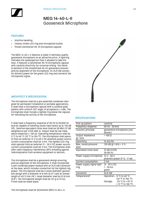
FEATURES• Intuitive handling• Clearly visible LED ring and microphone button • Proven Sennheiser KE 10 microphone capsuleThe MEG 14-40-L-II features a made in Germany quality gooseneck microphone on an attractive price. A lightring indicates the spokesperson that is allowed to take the floor. It features a Sennheiser KE 10 microphone capsule with cardioid directivity for universal miking. The flexib-le element of the streamlined 40 c m gooseneck ensures precise alignment of the microphone. An XLR 5M connec-tor delivers power for the green LED ring and connects the microphone signal.SPECIFICATIONSPick-up patterncardioidFrequency response 50 Hz - 20 k HzAcoustic principle gooseneck microphone (con-denser)Output impedance @ 1 k Hz < 100 ΩSensitivity15 m V/PaMax. sound pressure level130 d B @ 1 kHz < 3 %Equivalent noise level37 dB (CCIR)26 dB (A)Power supply microphone 12 V - 48 Vphantom power (P 12 - P 48)Current consumption 3 mAPower supply signal light ring 12 - 30 V DC 1 - 18 mAgreenConnector XLR-5M TemperatureF Operation:Storage:0 °C to 40 °C(32 °F to 104 °F)-25 °C to +70 °C(-13 °F to 158 °F)ARCHITECT‘S SPECIFICATIONThe microphone shall be a pre-polarized condenser desi-gned for permanent installation or portable applications. It shall have a microphone capsule with a cardioid polar pattern with uniform 120° angle of acceptance (-3 d B). The microphone shall include a lighted ring below the capsule for indicating the activity of the microphone.It shall have a frequency response of 50 H z to 20,000 H z and be capable of handling sound input levels up to 130 d B SPL. Nominal equivalent noise level shall be 26 d BA (37 d B weighted as per CCIR 468-3). Output shall be low impe-dance balanced (< 100 Ω). Operating temperature shall be 0 °C to 40 °C (32 °F to 104 °F). The microphone shall opera-te from an external 12 V to 48 V D C phantom power source; current consumption shall be 3 m A. The lighted LED ring shall operate from an external 12 – 30 V D C power source; current consumption shall be 3 m A. The microphone shall offer radio frequency interference (RFI) shielding against intermodulation from wireless equipment or devices.The microphone shall be a gooseneck design ensuring precise alignment of the microphone. It shall incorporate a self-contained power module with an XLR 5M connector at the base, which includes connection for the lighted ring power. The microphone shall be a small-diameter goosen-eck design with a diameter of 8 m m (0.31") and an overall length of 457.2 m m (18"). Head diameter shall be 22.8 m m (0.9"). The microphone weight shall be 147 g (4.72 o z). Finish shall be matte black.The microphone shall be Sennheiser MEG 14-40-L-II.POLAR PATTERN0°330°300°270°240°210°180°150°120°90°60°30°DIMENSIONS⌀ 0.9"[22,8 m m ]PIN ASSIGNMENT1 Microphone Ground2 Microphone +3 Microphone –4 LED Ground5 LED: 12 – 30 V32145FREQUENCY RESPONSEHz501002005001k2k5k10k20kd B V-20-30-40-50-60PRODUCT VARIANTS Product FeaturesMEG 14-40 B Art. no. 504791• Gooseneck with integrated Senn-heiser KE 10 microphone capsule• RF shielding against intermodu-lation from wireless equipment/devices• Streamlined design for seamlessintegration• Premium quality made in GermanyThe MEG 14-40 features a made in Germany qualitygooseneck microphone on an attractive price. It featuresan integrated Sennheiser KE 10 microphone capsule withcardioid directivity for universal miking and a streamlined40 c m gooseneck with a XLR 3M connector. The flexibleelement ensures precise alignment of the microphone.MEG 14-40-L B Art. no. 504792• Gooseneck with integrated Senn-heiser KE 10 microphone capsule• RF shielding against intermodu-lation from wireless equipment/devices• Streamlined design for seamlessintegration• LED ring for speech indication• AC/DC lightring powering• Premium quality made in GermanyThe MEG 14-40-L features a made in Germany qualitygooseneck microphone on an attractive price. A lightringindicates the spokesperson that is allowed to take thefloor. It features a Sennheiser KE 10 microphone capsulewith cardioid directivity for universal miking. The flexibleelement of the streamlined 40 c m gooseneck ensuresprecise alignment of the microphone. A XLR 5M connec-tor delivers power for the red LED ring and connects themicrophone signal.MEG 14-40-L-II B Art. no. 506398• Intuitive handling• Clearly visible LED ring and micro-phone button• Proven Sennheiser KE 10 micro-phone capsuleThe MEG 14-40-L-II features a made in Germany qualitygooseneck microphone on an attractive price. A lightringindicates the spokesperson that is allowed to take thefloor. It features a Sennheiser KE 10 microphone capsulewith cardioid directivity for universal miking. The flexibleelement of the streamlined 40 c m gooseneck ensuresprecise alignment of the microphone. An XLR 5M connec-tor delivers power for the green LED ring and connectsthe microphone signal.COMPATIBILE PRODUCTSProduct compatible withMEG 14-40 B MAT 133, MAT 133 S-B, SL Tablestand 133-S DW MEG 14-40-L B MAT 153, MAT 153-S und MAS 1MEG 14-40-L-II B SL Tablestand 153-S DW, MAT 153-S B。
PSAIM 版本 1.4 EIMp 用户指南说明书

for PSAIM™version1.4 EIMp User's GuideCopyright©2006-2016Siemens Energy,Inc.All rights reserved.Siemens Energy,Inc.Siemens Oil&GasConceptual&Engineering Services(CES)4615Southwest Freeway,Suite900Houston,TX77027/energyAll other company,product and service names and logos may be trademarks or service marks of their respective companies.Any rights not expressly granted herein are reserved.While every effort is made to ensure the accuracy of content,the product documentation could contain inaccuracies or out-dated material(which includes product screenshots and images)due to the large number of product enhancements being added.As such,the documentation set is subject to change at any time without notice.Refer to the README for documentation corrections and addendum.Please note,updates to the documentation set are reflected in the next general availability major release.Table of ContentsContacting Customer Support4 Technical Support Service(TSS)4 Technical Support Website(TSW)4 Incidents reported prior to July2015(Rightnow Portal)4 Incidents reported after July2015(SIOS Portal)4 Problems Accessing TSW4 Software Update(SU)5 Software Installation Service(SI)5 Postal Mail5 About This Guide6 1Using EIMp81.1Logging In82Users and Roles92.1Role Permissions92.1.1Creating and Editing Users112.1.2Resetting the Password132.1.3Creating and Editing Roles143Privilege17 4User Group18 5Plant Topology20Contacting Customer SupportSIEMENS provides a dedicated technical support team for their Process Safety&Conceptual Engineering Software.Customers that qualify for Customer Support Services are entitled to these services.For questions related to Customer Support and whether or not you qualify,please check with the support team for verification.The program includes the following services and is subject to a user registration procedure.l Access to Technical Support Service(TSS):Customer Support for problems related to software use post installationl Access to Technical Support Website(TSW):Web site including amongst others,information such as Frequently Asked Questions and technical documentation about products.l Software Updates(SU):Request for shipment of software upgrades such as major and minor releases,and service packs(for qualifying customers and users)l Software Installation(SI):Assistance with software installationTechnical Support Service(TSS)TSS can be reached through the Customer Care Center phone number:.International and within US:+1(800)333-7421The phone is answered24x7x365.However,response to service request tickets is provided only from Monday to Friday,business hours from8:00AM to5:00PM,Central Daylight Time,excluding US national holidays. Technical Support Website(TSW)Incidents reported prior to July2015(Rightnow Portal)Access to Rightnow Portal through Operations Intelligence,Safety&Conceptual Engineering Services Customer Support Site(https:///energy/sw-support)is available to all customers registered as a TSS user.TSW contains technical information such as Technical Documentation and Useful Hints.Customers are requested to check the status of incidents reported prior to July2015in the Rightnow Portal.After July 2015,this portal will no longer accept new Incident Requests.Incidents reported after July2015will be available in the SIOS portal below.Incidents reported after July2015(SIOS Portal)Access to Siemens Industry Online Support(SIOS)(https:///cs/#?lc=en-WW)is available to all registered er must be registered at the SIOS portal to be able to request er can register directly on the portal by clicking the above URL and then clicking Register in the upper right portion of the page.Note:The SIOS portal is the recommended means for requesting support.All emails are handled directly in the support ticketing system via the web portal above and are linked to ticket numbers so a full record of all email communications is maintainedProblems Accessing TSWIn case customers are facing problems accessing the TSW,please call+1-800-333-7421Software Update(SU)Qualified customers can request for or be notified when major,minor releases,patches,service packs are available for valid and licensed versions of the software product.Alternatively,customers can contact a TSS representative using the Customer Care Center phone number provided above to receive these updates by logging a ticket.Software Installation Service(SI)Qualified customers can contact the TSS team via the customer support center to request assistance with installation of licensed softwarePostal MailSiemens Energy,Inc.Customer Services,Oil,Gas&MarineProcess Safety& Conceptual EngineeringAttn.:Customer Support Department4615Southwest Freeway,Suite900Houston,TX77027USAAbout This GuideThis application includes complete documentation in an accessible PDF-based help system.The accessible PDF format is designed to provide easy navigation online.The file can also be printed out to provide a handy desktop reference.Formatting ConventionsBold Terms in bold describe an item that you select to carry out a given task.Example:Select the Print option.Italics Italicized terms pertain to the three(3)tabs of the Properties View.Example:Design specifications are edited in the Engineering tab.Dotted Underline Text with a dotted underline represent links to another topic within the document.Example:The model is illustrated in Figure1-47.In addition to these formatting conventions,this document uses the following styled paragraphs as visual cues for online viewing.l Notes are used to offer information that supplement important points of the main text.Tips suggest certain tech-niques and procedures that may help you achieve your task quickly.Unit or Case is not required.You can install each PSAIM™component separately.You simply uncheck thecomponents you do not want to install.The service is typically installed on the same server.l See Also notices provide you with additional references to similar topics and/or concepts within the guide as well as external sources.To continue with the Environment configuration and EIMp database upgrade,refer tothe"PS Environment Tool Configuration Guide."To continue with the Environment configuration and EIMp database upgrade,refer tothe"PS Environment Tool Configuration Guide."See the topic,Troubleshooting the Configuration for more information.l Web References point you to external web sites that give additional information on the given topic./energyl Important notices provide information that are required to completing a given task.Check-in all site-level items and approve the changes.Due to limitations with SQL Server,you must install the PSAIM™and EIMp databases onthe same system where SQL Server is hosted.l Warnings tell you that failure to take or avoid a certain action could result in loss of data or application mal-function.WarningDo not power off or unplug your machine during an upgrade.1 Using EIMp1Using EIMpThe EIMp(Engineering Information Management platform)is used for controlling user access and maintaining the plant topology(COMPANY/SITE/UNIT).1.1Logging InThere are two(2)ways to log into the EIMp program:l Using Windows credentials;l Using the application username and password.T o l o g o n t o E I M punch EIMp.The"Main"dialog appears.2.For Environment Server,type the EIMp server name and click the Connect icon.3.For Environment,click the down-arrow and select the EIMp Environment from the drop-down.4.Do one of the following:l Check Login using windows credentials.ORl Uncheck the windows credentials checkbox.The User Name and Password textboxes appear.Enter the User Name and Password.To change the password,see the topic,Resetting the Password.5.Click Log In.2Users and RolesThis section covers how to add,edit and delete users and roles.2.1Role PermissionsA user can have more than one role and the access to each COMPANY/SITE/UNIT can be associated with each unique role.Read Only User has the ability to view,but not to modifyManagement User has the ability to view and perform auditing tasksInspector User has the ability to perform inspection engineering tasksEngineer User has the ability to perform all engineering tasksChampion User has the application administrator accessAvailable roles for PSAIM™S it e S et t in gsConfiguration Settings AIM_MODIFY_SITESETTINGS x x---Drawing SettingsCorrosion Monitoring SettingsActivity SettingsView Site Settings AIM_VIEW_SITESETTINGSx x x x x User Settings x x x x x x Local Drawing SettingsLocal Data Logger SettingsSelecting ProfileCustom Filter SettingsWork Offline AIM_WORKOFFLINE x x x x x Equ ipm en tActivate/Inactivity Equipment AIM_ACTIVATE_EQUIPMENT x x---Privileges and permissions assigned for each role in PSAIM™Add/Copy/Edit/Delete Equipment AIM_MODIFY_EQUIPMENTx x x--View Equipment AIM_VIEW_EQUIPMENTx x x x x Co r r o s io n Mo n it o r in gActivate/Inactivate Component AIM_ACTIVATE_COMPONENTx x---Add/Copy/Edit/Delete/Group Component AIM_MODIFY_COMPONENTx x x--View Component AIM_VIEW_COMPONENTx x x x x T MLActivate/Inactivate TML AIM_ACTIVATE_TML x x---Add/Edit/Copy/Clone TML AIM_MODIFY_TML x x x--View TML AIM_VIEW_TML x x x x x S u r v eyAdd,edit and delete Survey AIM_MODIFY_SURVEY x x x--View Survey AIM_VIEW_SURVEY x x x x x Approve Survey AIM_APPROVE_SURVEYx x---S t r u c t u r al T m inAdd or edit Structural Tmin AIM_MODIFY_STMIN x x x--View Structural Tmin AIM_VIEW_STMIN x x x x x Ac t iv it yAdd/Edit/Delete/Complete Activity AIM_MODIFY_ACTIVITYx x x--View Activity AIM_VIEW_ACTIVITY x x x x xApprove/Reject Activity AIM_APPROVE_ACTIVITYx x---D r aw in gAdd,edit and delete Drawing AIM_MODIFY_DRAWING x x x--Privileges and permissions assigned for each role in PSAIM™View Drawing AIM_VIEW_DRAWING x x x x x Data LoggerAIM_DATALOGGERxxx--At t ac h m en t an d H is t o r y Add,edit and delete Attachment AIM_MODIFY_ATTACHMENT x x x --View Attachment AIM_VIEW_ATTACHMENT x x x x x Edit/Delete History AIM_MODIFY_HISTORYx x x --View History AIM_VIEW_HISTORY x x x x x Audit Trail AIM_AUDITTRAILxx-x-R epo r t s Add or edit Reports AIM_MODIFY_REPORT x x x x -Delete Reports AIM_DELETE_REPORT x x Delete Own Delete Own-View Reports AIM_VIEW_REPORTxxxxxS APAdd or edit SAP AIM_MODIFY_SAP x x ---View SAP AIM_VIEW_SAP x x x x x HelpAIM_VIEW_HELPxxxxxPrivileges and permissions assigned for each role in PSAIM™2.1.1Creating and Editing UsersT o c r e a t e a u s e r a n d a s s i g n r o le s1.From the main menu,click User .The "User -User Role View"screen appears.2.Click the Add button()OR the Edit button().The"User Administration"screen appears.Fields with a red asterisk(*)are required.These represent the minimuminformation needed to create the user.3.Select an Application.4.Check the Active checkbox.To deactivate a user,you simply deselect(uncheck)the Active checkbox and click Save.5.For Log In,enter the Windows user name.6.Check the Is Windows User checkbox.7.Enter the user's First and Last names and an Email.8.For each Role/User Group/Privilege/Business Unit,select an available item to assign to the user and click theright-arrow()button to add it to the Selected column.To remove an item from the Selected column,select the item and click the left-arrow()button.A role with an asterisk(*)indicates that is a system role.So,you must select a resource in order toassign the system role to the user.For more information on PSAIM™roles and their assigned permissions,see the topic,About Roles.9.For system roles:From the Selected column for Roles,select the system role and click the Edit Resources button.This updates the resources for the selected role.If new user information has not been saved,a dialog appears prompting youto save the user information.Click Yes to save and continue.10.Click Save.For Application Users(not Windows Users),a password is automatically generated and the following message appears.To copy this temporary password to the clipboard,press CTRL+SHIFT+C.Upon the next log-on,you will need to reset your password.T o de l e t e a u s e r1.From the main menu,click User.The"User-User Role View"screen appears.2.Select(to highlight)the user you want to remove.A user cannot be deleted if there are Role(s),Privilege(s),User Group(s),and or Business Unit(s)associatedwith the user.3.Click the Delete button().2.1.2Resetting the PasswordWhen resetting your password,the new password must be:l Alphanumeric,consisting of only letters(a-z,A-Z)and/or numbers(0-9);l Six to fifteen characters long;l Different from the previous password.T o r e s e t t he p a s s w o r d1.Log onto EIMp.The log on page appears.2.Enter your existing password,then enter(and re-enter)the new password.3.Click Log In.2.1.3Creating and Editing RolesThis section describes how to add,edit and delete a user role. It also shows all the user(s)assigned to each role.A role with an asterisk(*)indicates that is a system role.System roles are pre-defined and cannot be edited ordeleted.T o c r e a t e(o r e di t)a r o l e1.From the main menu,click Role.The"User Role-User View"screen appears.2.Click the Add button()OR the Edit button().The"Role Administration"screen appears.Fields with a red asterisk(*)are required.These represent the minimum3.Select an Application.4.Check the Active checkbox.To deactivate a user,you simply deselect(uncheck)the Active checkbox and click Save.5.Enter a Role Name.6.For each User/Privilege/User Group,select an available item to assign to the role and click the right-arrow()To remove an item from the Selected column,select the item and click the left-arrow()button.7.Click Edit Resources,which is located at the upper,right-hand corner of the dialog box.The"Assign resources for"dialog appears.8.Check the location(s).In order to save,each application role must have at least one resource assigned to it.9.Click OK to assign the resource(s)for the application role.This returns you to the"Role Administration"screen.A resource inherits permissions for all sub-resources.For example,assigning a COMPANY to a user grantsthat user access to all SITES and UNITS.Similarly,assigning a SITE to a user grants that user to the UNITSunder the SITE.10.Click Save.T o de l e t e a r o l e1.From the main menu,click Role.The"User Role-User View"screen appears.2.Select(to highlight)the role you want to remove.A role cannot be deleted if there are User(s),Privilege(s),and/or User Group(s)associated with the role.3.Click the Delete button().3PrivilegeThis dialog shows all the user(s)who are assigned to all the available privilege(s).This dialog simply displays the users.There are no options to configure.4User GroupThis section describes how to add,edit and delete user group. It also shows all the user(s)who are assigned to each user group.T o c r e a t e(o r e di t)a u s e r g r o u p1.From the main menu,click User Group.The"User Group-User View"screen appears.2.Click the Add button()OR the Edit button().The"User Group Administration"screen appears.Fields with a red asterisk(*)are required.These represent the minimuminformation needed to create the user group.3.Select an Application.4.Enter a User Group Name.5.For each User/Role/Privilege,select an available item to assign to the user group and click the right-arrow()button to add it to the Selected column.To remove an item from the Selected column,select the item and click the left-arrow()button.6.Click Save.T o de l e t e a u s e r g r o u p1.From the main menu,click User Group.The"User Group-User View"screen appears.2.Select(to highlight)the user group you want to remove.A user group cannot be deleted if there are User(s),Privilege(s),and/or Role(s)associated with the usergroup.3.Click the Delete button().5 Plant Topology5Plant TopologyThis section describes how to configure the plant topology types(COMPANY/SITE/UNIT)and to add,edit and delete the plant topology entity.It is highly recommended you fully configure the plant topology prior to using the PSAIM™application.Changes made to plant topology is reflected in the application after10minutes.T o c o n f i g u r e t he p l a n t t o p o l o g y1.From the main menu,click Plant Topology.The"Plant Topology"screen appears.The Delete button for the Type Administration group is disabled to allow aone-time set-up.First,you define the type.2.For Type Administration,either click the Add button()OR select a plant topology type.3.Do one of the following:l To add a parent-level type,enter the Name and click Save Type.l To add a child-level type,enter the Name,then select the Parent,and click Save Type.Fields with a red asterisk(*)are required.Next,define the entity(or the plant topology data).5 Plant Topology214.For Entity Administration ,either click the Add button ()OR select a plant topology entity.5.Select a Parent from the drop-down list.6.Then,enter a Name ,Code ,and Address .7.Click Save Entity .T o de l e t e a n e n t i tyPrior to deleting a parent entity,all children must first be deleted.1.Select (to highlight)the entity you want to remove.2.Click the Delete button ().。
- 1、下载文档前请自行甄别文档内容的完整性,平台不提供额外的编辑、内容补充、找答案等附加服务。
- 2、"仅部分预览"的文档,不可在线预览部分如存在完整性等问题,可反馈申请退款(可完整预览的文档不适用该条件!)。
- 3、如文档侵犯您的权益,请联系客服反馈,我们会尽快为您处理(人工客服工作时间:9:00-18:30)。
测量中的数据集
项目管理的第三层级
数据集(Data Set) – 显示数据是实测( Measured )数据(或是野外数据 ),模拟得到的( Simulated )数据,或是处理后的( Processed )数据。 域类型(Domain Type) – 显示数据是频率域( Frequency )、频谱域( Spectral )、时间域( Time )、或者是静态域( Static )的数据。 改变名称(Change Name) – 在任何时候键入新的名称并按下改变名称按键可以更改数据集的名称。 模型名称 (Model Name) – 数据集的第二个标识字符串,可记录关于数据集的额外细节。 配置 (Configuration) – 查看和修改涉及测量的配置信息。 模型(Model) – 查看和修改模型的配置信息,导入多面体文件,地形等等。 网格(Grids) – 网格管理工具 – 包含了已生成的针对本数据集的所有网格。
过滤测量编辑器 曲线图 可视化工具 网格等值线图 拟断面 CDI浏览器 等值线图
网格工具
数据显示工具集
等值线图 以三维曲面显示网格化的数据。显示一维 三维可视化工具
最先进的三维可视化和模型构 和三维反演的三维体积等值线,并提供剖面切割工具。 建工具让你在三维空间中结合模型结构查看数据(实 网格等 网格等值线图 显示网格工具创建的网格数据。 测数据、正演数据和反演数据)。数据可以曲线、矢 量、真实三维曲面或者等值线曲面形式展现。允许对 多重网格图 在同一时间显示最多四个网格。 异常体的位置、形状和大小进行详细分析。可查看多 达三个数据通道的数据。可同时显示来自多个模型的 拟断面 依据数据类型,通过绘制与时间或频率比对 数据曲线或模型数据与实测数据的曲线以供比较。 的数据产生一种拟断面显示。
合并数据集
主窗口 开关主数据库窗口。
数据导入
导入工具集 提供一组导入工具,允许将实测数 据带入数据库。数据文件应为符合设备生产厂 家文件格式的文件,或为ASCII柱状数据格式文 件,或为.qct 格式的文件。 生产厂家数据格式 使你能够将符合设备生产厂 家标准文件格式的实测数据带入数据库中。包 括:Terra TEM、TEM Fast、CRONE、 GEONICS TEM、IP6和 AIRBORNE TEM (GeoTEM 和 QUESTEM)数据。 .qct 格式: QCTool 是一款功能非常广泛且廉价的 产品。用于数据处理和品质控制。许多类型的 数据可以通过这种格式导入。.gdb 文件的导入 就是通过首先将.gdb 文件转为 .qct 文件来完成 的。
a) MODELS –反演模型( *.pex, *.mag, *.grv, *.res) – ASCII 文件包含了反演模型 b) Griddata – *.dat - (二进制文件) c) PlotSettings – 储存用户设定的用于展示曲线图和网格图的设置参数 d) Polyhedron – 这里存储了数据库中所有的多面体。如果一个多面体文件是由另 一个数据源导入,那么在此会产生一个副本以供本数据库使用 e) Surveycomments - *.pxt –可以在主数据库界面使用和编辑 f) Temp – 临时文件夹。 EMIGMA 用来存储辅助信息 g) Log – 保存反演日志, 以便恢复反演设置
数据库菜单
数据库(Database) 工具集用于管理数据库 *.mdb 文件。允许创建一个新的
数据库,打开一个已经存在的数据库,导入数据到数据库,从数据库导出数据,搜索一个数 据集,合并数据集,以及退出 EMIGMA 程序。
视图(View ) 工具集用于管理 EMIGMA 主界面的视图选项,包括工具栏,状态栏
乘以一个数(Multiply Data by) -除以一个数(Divide Data by) 对数据加减一个值(Shift Data ) -设置“无数据”(Set NODATA) 新值(New Value ) -反转符号(Reverse Sign) 删除点(Delete Points ) -反转测线方向(Reverse Profile Direction) 每隔N个点删除一个点(Delete Every )-删除时间通道(Delete Time Channel) 删除频率(Delete Frequency ) -删除接收器(Delete Receiver) 删除发射器(Delete Transmitter ) -删除发射接收器间距(Delete Separation)
当你对校正满意时,选择保存( 保存(Save)。
测量检查
测线排序 利用线标, X 位置或者 Y
位置对测线进行排序。
对测线位置使用数字(Digital)或空间 (Spatial)过滤器。数字过滤器包括中值(Median) 、高 斯(Gaussian) 、均值(Mean)和 Savitzky-Golay(常规或 非常规)过滤器。空间过滤器包括中值、高斯、均值和 Savitzky-Golay (空间半径)过滤器。
新的 EMIGMA 更新。
数据库 工具集
新建数据库 保存数据库 工作区 主窗口 刷新 导出 打开数据库 搜索数据集 导入 合并数据集
新建数据库 在 EMIGMA 程序中创建一个新的 刷新 更新数据库中数据集的显示。
数据库文件(*.mdb)。
导入 包括一组将数据导入数据库的工具。 打开数据库 在 EMIGMA 中打开一个已经存在
EMIGMA 数据库结构
EMIGMA – 数据库结构
EMIGMA 被设计为既能提供一般数据分析, 被设计为既能提供一般数据分析,同时又是具有极高水平的一种工具集成。 同时又是具有极高水平的一种工具集成。这些工具用于数 据解释, 建模和反演。 建模和反演。 因此, 因此,相比简单的数据库应用, 相比简单的数据库应用,它具有更广泛的能力。 它具有更广泛的能力。 每一个新的数据库应该拥有自己的目录。 每一个新的数据库应该拥有自己的目录。在这个目录中有: 在这个目录中有: - 一个 EMIGMA 数据库, 它包括一个 *.mdb 文件 - 相关联的文本文件 (ASCII 格式) 这些文件被命名为 “ N.dat” – 在 EMIGMA 的主界面中,当一个数据集被选择时,其相应的文本文 件名被给出。 - 相关联的子目录
EMIGMA
高级版与专业 版
EMIGMA 概要
EMIGMA – 数据库版 数据库设计的目的 · · · · · · ·
减少用于建模和分析数据的时间 增强数据分析的能力 提高后期提供工作报告及查找数据解释的能力 集成全部的工具到一个平台 包含了容易使用的数据编辑, 压缩, 过滤和处理的方法 允许建立大型数据集以便分析航空测量数据 为反演工具及其与正演工具的集成提供了一个框架
操作
从以下选择
-
根据数据类型(Data Type),发射器( Transmitters),接受器(Receivers), 时间通道(Time Channels)或频率( Frequencies),响应类型(Responses) 和相量(Phasor)等选择数据通道。
所有的时间通道 所有的测点 所有的测线
数据库中的项目
项目管理的第一层级
重新命名(change Name) – 在任何时候你都可以通过键入项目名称然后点击重新命名按钮来重新命名项目。 删除项目(Delete Project) – 首先选择项目, 然后按删除项目按键。 创建项目(Create Project) –点击创建项目按键建立一个新项目。
导出
势能场FFT 处理 电导率深度成像
正演模拟
数据库 项目, 测量 和数据集管理 测量检查 - 检查测线和数据点 - 测线过滤 - 测线排序 数据/测点 校正 - 删除不好的测点 - 删除发射器接收器组 - 反转符号 - 对数据加减一个值 - 乘以系数 - 其它 数据精减 - 利用正演计算 不同反响的数据
应用系统熟悉所有的结构,不需要用户管理。但是当发送数据库到其他用户时,切记打包全部的包含了 完整文件夹信息的目录结构。EMIGMA V8.5及以后版本含有一个功能,允许用户直接输出和打包,以 便于传输。
打开数据库 主窗口
三维可视化 合并数据集 多重网格图 拟断面 搜索数据集 数据表 测量编辑器 网格化 刷新 导入 CDI 浏览器 XY 曲线图 网格视图 等值线图 数据抽取及过滤 新建数据库
多面体产生器 断层显示 源配置 变换器
一维反演 三维反演
数据组织结构
在建模和反演操作中用户可以很容易地生成许多文件。模型被组织在数据库结构 中以便稍后很容易地获得数据解释的状况。 多重数据集和模型可以保存在单一的数据库文件中。EMIGMA提供了多重组织层 级允许各种组织准则存在以适应用户的喜好。例如, 用户可以通过数据解释项目或 数据类型进行组织;或者简单地把所有项目和数据组织在一个主数据库中。用户 可以在一个单一项目(一个数据库文件中的组织层级)中组织各种数据集以便于更容 易地分析不同类型的数据和集成不同类型数据的模型。 现在允许有新的数据通道, 诸如: GPS (x,y,z) , 高度表, 和基准时间( FID )。 更新 – 可以将重力场数据作为经过配置的地球物理数据导入你的数据并且构建它 们的图像。 们的图像。 – V8 包含了重力场模型和反演。 包含了重力场模型和反演。
和数据库颜色的切换显示。
数据可视化(Data Visualization) 允许用不同的方法观察和
显示数据,以便于分析和报告。
处理工具集(Processing Tools) 是一个包含各种工具的组合,
用于处理测量的数据。
帮助(Help) 显示在线帮助标题,EMIGMA 程序版本,许可证细节和状态,下载最
项目中的测量 项目管理的第二层级
测量名(Survey Name) – 任何时候只要键入新的名字,然后按下改变( Change)按键就可以重新命名。 测量注释 (Survey Comments) – 输入并保存关于测量的说明。 加一个测量(Add Survey) – 生成一个新的合成测量。 备份(BackUP) – 生成一个包含了所有数据集的测量的副本。 删除测量 (Delete Survey) – 在任何时候要删除一个测量,选中它并按下删除测量按键。 复制 (Copy)– 放置选中的测量到 EMIGMA 剪切板。 粘贴(Paste) – 将 EMIGMA 剪切板中的测量添加到当前项目中。