实时控制传输通讯协议RealTime Control and Translate Protocol
实时传输协议RTP与RTCP资料
-- 作者:vcfans-- 发布时间:2007-3-2 15:52:59-- 流媒体专题—传输协议实时传输协议RTP与RTCPRTP(Real-timeTransportProtocol)是用于Internet上针对多媒体数据流的一种传输协议。
RTP被定义为在一对一或一对多的传输情况下工作,其目的是提供时间信息和实现流同步。
RTP通常使用UDP来传送数据,但RTP也可以在TCP或ATM等其他协议之上工作。
当应用程序开始一个RTP会话时将使用两个端口:一个给RTP,一个给RTCP。
RTP本身并不能为按顺序传送数据包提供可靠的传送机制,也不提供流量控制或拥塞控制,它依靠RTCP提供这些服务。
通常RTP算法并不作为一个独立的网络层来实现,而是作为应用程序代码的一部分。
实时传输控制协议RTCP。
RTCP(Real-timeTransportControlProtocol)和RTP一起提供流量控制和拥塞控制服务。
在RTP会话期间,各参与者周期性地传送RTCP包。
RTCP包中含有已发送的数据包的数量、丢失的数据包的数量等统计资料,因此,服务器可以利用这些信息动态地改变传输速率,甚至改变有效载荷类型。
RTP和RTCP配合使用,它们能以有效的反馈和最小的开销使传输效率最佳化,因而特别适合传送网上的实时数据。
6.2.1 RTP数据传输协议RTP提供端对端网络传输功能,适合通过组播和点播传送实时数据,如视频、音频和仿真数据。
RTP没有涉及资源预订和质量保证等实时服务,RTCP扩充数据传输以允许监控数据传送,提供最小的控制和识别功能。
RTP与RTCP设计成独立传输和网络层。
2.1.1 RTP固定头RTP 头格式如下:-----------------------------------------------------------------------------------------------|V=2|P|X| CC |M| PT | 系列号 |-----------------------------------------------------------------------------------------------| 时标 |-----------------------------------------------------------------------------------------------| 同步源标识(SSRC) |-----------------------------------------------------------------------------------------------| 作用标识 (CSRC) || .... |-----------------------------------------------------------------------------------------------开始12个八进制出现在每个RTP包中,而CSRC标识列表仅出现在混合器插入时。
RTSP协议实时流传输协议简介
RTSP协议实时流传输协议简介RTSP(Real-Time Streaming Protocol)是一种用于实时流传输的网络协议。
它的主要作用是控制多媒体服务器上的流媒体数据,实现实时的传输和控制。
一、RTSP协议的概述RTSP协议是由IETF(Internet Engineering Task Force,互联网工程任务组)制定的一种应用层协议。
它通过控制服务端上的媒体数据流,为客户端提供实时播放、暂停、倒带、快进等控制功能。
二、RTSP协议的特点1. 实时性:RTSP协议能够提供低延迟的实时传输,适用于对实时性要求较高的应用场景,如视频监控、视频会议等。
2. 灵活性:RTSP协议支持多种编解码器、多种传输协议,可以适应不同的网络环境和设备要求。
3. 扩展性:RTSP协议允许通过扩展方式定义新的方法和参数,以满足个性化的业务需求。
三、RTSP协议的工作原理1. 客户端发送请求:客户端通过建立RTSP连接向服务器发送命令请求,如PLAY、PAUSE、SETUP等。
这些命令指示服务器开始、暂停或切换媒体流的传输。
2. 服务器响应请求:服务器接收到客户端的请求后,将相应的媒体流数据传输给客户端,并返回相应的状态码和信息。
3. 媒体流传输:客户端通过UDP或TCP协议与服务器建立数据传输通道,实现实时媒体流的传输。
4. 控制指令交互:客户端与服务器之间进行控制指令的交互,如快进、快退、暂停等,实现对媒体流的控制。
四、RTSP协议与RTP协议的关系RTSP协议通常与RTP(Real-Time Transport Protocol)协议配合使用。
RTP协议负责将媒体数据进行分片并在网络中传输,而RTSP协议则负责控制RTP协议的传输和播放。
两者配合使用,可以实现流媒体的实时传输和控制。
五、RTSP协议的应用场景1. 视频监控:RTSP协议适用于实时监控系统,可以帮助实现远程监控图像的实时传输和控制。
2. 视频会议:RTSP协议可以实现多方视频会议中的视频数据传输和控制,保证会议的实时性和流畅性。
实时控制系统的应用:异步串行通信协议说明书
1300 Henley Court Pullman, WA 99163509.334.6306Lab 4b: Application of Asynchronous Serial Communications Protocol for Real-time ControlRevised May 23, 2017This manual applies to Unit 4, Lab 4b.1 Objectives1. To control and monitor the operations of a stepper motor using serial communications between a PIC32microprocessor and a computer terminal.2. To implement real-time control using a preemptive foreground-background task scheduling scheme.3. Simulate an environment that provides both local and remote control of a real-time system.2Basic Knowledge1. Elements of ASCII text encoding .2. I/O configuration for PPS Processors .3. How to initialize special function using the PLIB functions.4. How to program the PIC32 processor to both generate and receive and decode serial text data.3 Equipment List3.1 Hardware1. Basys MX3 trainer board2. Workstation computer running Windows 10 or higher, MAC OS, or Linux3. 2 Standard USB A to micro-B cables4. 4-wire stepper motor5.5V, 4A DC power supplyIn addition, we suggest the following instruments:6. 3.2 SoftwareThe following programs must be installed on your development work station:1. Microchip MPLAB X® v3.35 or higher2. PLIB Peripheral Library3. XC32 Cross Compiler4.WaveForms 2015 (if using the Analog Discovery 2)5.PuTTY Terminal Emulation.4 Project Takeaways1.Knowledge of a PC terminal emulation program.2.How to develop a library of PIC32 software to provide bi-directional communications of single charactersand strings of characters.3.How to generate and decode ASCII text strings.4.How to implement a human-machine interface (HMI) using point-to-point serial communications.5 Fundamental ConceptsSerial communication is the process of sending data one bit at a time, sequentially, over a communication channel or computer bus. This is in contrast to parallel communication, where several bits are sent as a whole on a link with several parallel channels. Both parallel and serial communications have handshaking requirements to synchronize data transfers. Although parallel communications generally have a speed advantage over serial communications, the primary advantage for serial communications is the reduced number of processor I/O pins and connecting wires or conductors.6 Problem StatementIt requires all of the elements of software code developed and hardware used in previous labs, as well as additional hardware and software to support the serial communications with the PC. This project will require you to input text data from the serial port that will set the direction, mode, and speed of the stepper motor. This interface will be in addition to all of the controls provided in Lab 2b. The text from the serial port will be echoed to the LCD. It will be good for you to review the documentation on how the following text manipulating functions are implemented: printf, sprintf, scanf, and strcmp.7 Background InformationLab 4a introduced the basic concepts of UARTs and asynchronous serial communications. Lab 4b extends that knowledge by specifying a system that is capable of two independent control and monitoring locations which is common to many industrial applications, such as gantry cranes and processing plants. In this lab, the switches and push buttons on the Basys MX3, as used in lab 2b, will perform the local control functions. The Basys MX3 LCD will be used as the local display. The UART serial connection will provide the basic control and display functionality using a workstation terminal emulator program.8 Lab 4b8.1 Requirementsmunications will use the PC terminal emulation program for a bit rate of 38400, even parity, 8 databits, and one stop bit.2.Local Control Specifications of Stepper Motora.Direction and Mode controli.BTNR controls the direction of rotor rotation of the stepper motor.ii.BTND controls the stepper motor step mode.iii.The speed of rotation must be the same regardless of stepper mode operation.b.The speed of rotation is set by the hexadecimal value set on the eight slide switches. SW7 is themost significant bit and SW0 is the least significant bit.c.The speed of the motor is to be displayed on the 4-digit 7-segment LED display in RPM.d.The four digits of the Basys MX3 7-segment display are continually updated with a 1 mspersistence (each digit must be turned on for 1 ms). The four digits will be lit in a round-robinfashion in a foreground operation managed by Timer 1 ISR.e.Stepper motor outputs are changed in the Timer 1 ISR using the period as determined by theslide switch settings. The period is determined by converting RPM to ms delay between steps.f.The BTNC push button controls the ON/OFF state of the LED0 in a push-on/push-off manner.i.When LED0 is changed to “ON,” print “Stepper motor under local control” on the serialmonitor. Then read switches and push buttons to set the stepper motor operations andreport the status of the remote serial monitor via UART 4.ii.When LED0 is changed to “OFF,”print “Stepper motor under remote control.” Followed by the message “Enter data [DIR] [MODE] [###] for [DIR] = CW or CCW, [MODE] = FULLor HALF, and [###] = stepper motor speed in RPM” to the remote serial monit or viaUART 4.3.Remote Control Specificationsa.Any change of the stepper motor operations made by local controls must be reported to theserial terminal using the format “[DIR] [MODE] [###]” for [DIR] = “CW” or “CCW”, [MODE] =“FULL” or “HALF”, and “[###]: = stepper motor speed in RPM.”b.When the system is under remote control operation, stepper motor control is implementedusing a command string in the following format: [DIR] [MODE] [###][RETURN] where the textfields are described in 2.f.ii. above. The [RETURN] character is generated when the monitor“Enter” key is pressed. All command fields must contain valid text or range of numbers,otherwise the entire command is ignored and an error message is sent back to the monitor usingthe text “Bad entry\n\r.”8.2 Design Phase1.Develop a data flow diagram for the software components needed for the requirements of Lab 4b.2.Schematic diagrams: Provide a block diagram of the equipment used for Lab 4b.3.Flow diagrams: Provide a complete software control flow diagram for Lab 4b.4.Develop a test plan that lists each requirement stated in section 8.1, including a column for PASS/FAIL. 8.3 Construction Phaseunch a new Microchip MPLAB X project called Lab4b. Add the config_bits.h file to the project.2.Add lab4b.c file to project Lab4b. The initialization segment of the main function should configure all I/Opins, initialize UART 4, initialize the Timer 2 interrupts, set LED0 on (indicating local operating mode), and set all global variables.3.Add all stepper motor files used in Lab 2b to the project.4.Add the UART functions developed for Lab 4a.5.This program will contain the function main and process the serial text. Put the following tasks inside thewhile(1) loop:a.Check for BTNC being pressed.b.Check if a command line of text has been entered.c.The direction and mode string variables can be decoded using the string compare function“strcmp.” An example of using this function would be:x = strcmp(mode_txt,”FULL”);d.Only if the st ring of data in mode_txt is exactly equal to FULL will the value of “x” equal zero. Youmust include <string.h> to be able to use this function.e.After decoding the string data, set the global variables that control direction, mode, and stepdelay (computed from RPM setting).8.4 Testing1.Run the project. Complete the test plan that was developed above.9 Questions1.Why is it appropriate that the UART getstrU4 function be a background process?2.What are the advantages of using serial communications to link to processors?3.What are the disadvantages of using serial communications to link to processors?10 References1.PIC32MX330/350/370/430/450/470 Family Data Sheet2.“Using the USART in Asynchronous Mode”,/downloads/en/DeviceDoc/usart.pdf3.“Asynchronous Communications with the PICmicro® USART”,/downloads/en/AppNotes/00774a.pdf4.RS-232, RS-422, RS-423, RS-485 Asynchronous communications.Appendix A: Basys MX3 Schematic DrawingsFigure A.1. PIC32MX370 to FT232RQR IC schematic diagram.Figure A.2. LCD and switches on the Basys MX3 that controls the stepper motor speed.Figure A.3. PuTTY screenshot generating LCD display.Figure A.4. PuTTY screenshot of serial configuration for 19200 BAUD and ODD parity.Appendix B: Allocating a Heap in MPLAB XIf when compiling your project you see an error like: "ld.exe Error: A heap is required, but has not been specified," this is because you need to specify a heap size by setting “Run” ->“Set Project Configuration” -> “Customize…”. Go to the “xc32-ld” category (under “XC32 (Global Options)”) -> “Heap size (bytes)” to “0” The configuration window should look like Fig. B.1. Click on the “Apply” button followed by clicking on the “OK” button. See/mplabx:creating-a-heap.Figure B.1. Allocating Heap size.。
实时传输协议(RTP)和实时控制协议(RTCP)
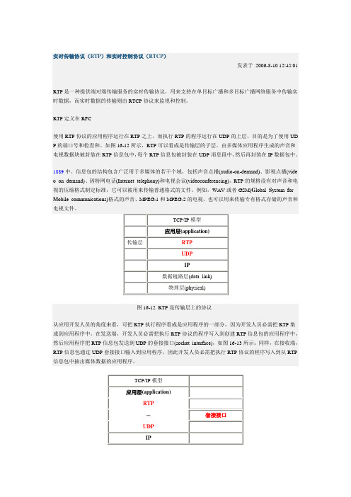
图16-12 RTP是传输层上的协议从应用开发人员的角度来看,可把RTP执行程序看成是应用程序的一部分,因为开发人员必需把RTP集成到应用程序中。
在发送端,开发人员必需把执行RTP协议的程序写入到创建RTP信息包的应用程序中,然后应用程序把RTP信息包发送到UDP的套接接口(socket interface),如图16-13所示;同样,在接收端,RTP信息包通过UDP套接接口输入到应用程序,因此开发人员必需把执行RTP协议的程序写入到从RTP 信息包中抽出媒体数据的应用程序。
图16-13 RTP和UDP之间的接口现以用RTP传输声音为例来说明它的工作过程。
假设音源的声音是64 kb/s的PCM编码声音,并假设应用程序取20毫秒的编码数据为一个数据块(chunk),即在一个数据块中有160个字节的声音数据。
应用程序需要为这块声音数据添加RTP标题生成RTP信息包,这个标题包括声音数据的类型、顺序号和时间戳。
然后RTP信息包被送到UDP套接接口,在那里再被封装在UDP信息包中。
在接收端,应用程序从套接接口处接收RTP信息包,并从RTP信息包中抽出声音数据块,然后使用RTP信息包的标题域中的信息正确地译码和播放声音。
如果应用程序不使用专有的方案来提供有效载荷类型(payload type)、顺序号或者时间戳,而是使用标准的RTP协议,应用程序就更容易与其他的网络应用程序配合运行,这是大家都希望的事情。
例如,如果有两个不同的公司都在开发因特网电话软件,他们都把RTP合并到他们的产品中,这样就有希望:使用不同公司电话软件的用户之间能够进行通信。
这里需要强调的是,RTP本身不提供任何机制来确保把数据及时递送到接收端或者确保其他的服务质量,它也不担保在递送过程中不丢失信息包或者防止信息包的次序不被打乱。
的确,RTP的封装只是在系统端才能看到,中间的路由器并不区分那个IP数据报是运载RTP信息包的。
RTP允许给每个媒体源分配一个单独的RTP信息包流,例如,摄像机或者麦克风。
rtc协议

RTC协议什么是RTC协议RTC(Real-Time Communication)协议是一种实时通信协议,用于在互联网上进行实时音视频通信。
它是一种对等通信协议,可以在不同的终端设备之间进行双向通信,包括音频、视频和数据的传输。
RTC协议在实时通信领域发挥着重要的作用,它为我们提供了一种高效、稳定的通信方式,使得远程交流变得更加便捷。
在各种应用场景中,RTC协议被广泛应用于视频会议、在线教育、远程医疗、社交娱乐等领域。
RTC协议的特点实时性RTC协议的最大特点就是实时性,它能够在网络环境下提供低延迟、高质量的音视频传输。
这对于一些需要及时交流的场景非常重要,比如视频会议中的实时互动、在线教育中的教师和学生的即时交流等。
可靠性在实时通信中,信号的稳定传输是至关重要的。
RTC协议采用了可靠的数据传输机制,确保音视频的准确传递,避免了数据丢失和传输错误的问题。
兼容性RTC协议具有良好的兼容性,可以在不同的终端设备上运行,包括PC、手机、平板等。
这使得用户可以在不同的设备上进行实时通信,极大地提高了通信的便捷性和灵活性。
安全性RTC协议在数据传输过程中采用了加密算法,保证了通信的安全性。
这对于一些涉及敏感信息的场景非常重要,比如远程医疗中的病人隐私保护、在线支付中的支付安全等。
扩展性RTC协议具有良好的扩展性,可以根据需求进行定制和扩展。
开发者可以根据实际需要,添加自定义的功能和特性,以满足不同场景下的需求。
RTC协议的应用场景视频会议RTC协议在视频会议中扮演着重要的角色。
通过RTC协议,参会人员可以在不同地点实时进行视频通话和互动,实现远程会议的目的。
这大大节省了时间和成本,提高了会议的效率。
在线教育随着互联网的普及,越来越多的教育资源可以通过网络进行传播和共享。
RTC 协议在在线教育中提供了实时的教学环境,学生可以与教师进行互动交流,获得更好的学习效果。
远程医疗RTC协议在远程医疗中发挥着关键作用。
rtc原理
rtc原理RTC原理:实时传输控制的基本概念与应用一、引言实时传输控制(Real-time Transport Control,RTC)是一种用于实时传输数据的通信协议。
它基于传输控制协议(Transport Control Protocol,简称TCP)和用户数据报协议(User Datagram Protocol,简称UDP),通过网络传输实现实时数据的传输与控制。
本文将介绍RTC的基本原理、应用场景以及在视频会议、在线游戏等领域的具体应用。
二、RTC的基本原理RTC的基本原理是通过网络传输实时数据流,保证数据的实时性和稳定性。
其中,TCP协议提供了可靠的数据传输机制,确保数据的完整性和顺序性;而UDP协议则提供了低延迟的数据传输特性,适用于实时性要求较高的场景。
1. 数据打包与拆包在RTC中,数据包是实时传输的基本单位。
发送端将需要传输的数据按照一定的规则打包成数据包,然后通过网络发送给接收端。
接收端根据数据包头部的信息,将数据包拆包成原始数据。
这样,数据可以按照一定的顺序和时间间隔进行传输和接收。
2. 数据传输与控制在数据传输过程中,发送端和接收端通过握手机制建立连接,确保双方可以互相识别和通信。
发送端将数据包发送给接收端,接收端通过接收和处理数据包,实现对数据的解码和展示。
同时,RTC还通过控制信息实现对数据传输的控制,包括数据流的开启、关闭、丢包重传等。
三、RTC的应用场景RTC的应用场景非常广泛,涵盖了很多领域。
下面以视频会议和在线游戏为例,具体介绍RTC在这些场景中的应用。
1. 视频会议在视频会议中,多个参会人员通过网络传输实时的音视频数据。
RTC通过保证数据的实时性和稳定性,确保参会人员能够实时地观看和听到其他与会人员的画面和声音。
同时,RTC还支持屏幕共享、实时聊天等功能,提升了会议的互动性和效率。
2. 在线游戏在在线游戏中,玩家通过网络传输实时的游戏数据,与其他玩家进行游戏对战或合作。
传输控制协议介绍
传输控制协议介绍一、传输控制协议的概念传输控制协议(TCP,Transmission Control Protocol)是一种面向连接的、可靠的、基于字节流的传输层通信协议。
它在互联网协议(IP)网络通信中起着重要的传输控制作用,确保数据能够可靠、有序、错误校验地从一个主机传输到另一个主机。
TCP提供了一种可靠的、有序的和错误校验的数据传输方式,能够自动处理数据流量控制和数据包的重新发送等任务。
二、TCP的主要特点1.面向连接:TCP是一种面向连接的协议,需要先建立连接才能进行数据传输。
在传输数据之前,需要通过三次握手(three-way handshake)建立可靠的连接。
2.可靠传输:TCP提供了可靠的数据传输服务,能够保证数据的有序、可靠、错误校验的传输。
它通过确认机制、重传机制、流量控制和拥塞控制等机制实现可靠性。
3.字节流:TCP将数据看作字节流,没有消息边界的概念。
发送方和接收方以字节流的形式发送和接收数据,不需要关心数据的具体格式和分段。
4.错误校验:TCP提供了错误校验功能,通过校验和(checksum)对数据包进行错误检测,确保数据在传输过程中没有被损坏或篡改。
5.流量控制:TCP通过流量控制机制防止接收方来不及处理接收到的数据而造成数据丢失。
流量控制基于滑动窗口协议(sliding window protocol),通过动态调整窗口大小来控制发送方的发送速率。
6.拥塞控制:拥塞控制是为了防止过多的数据包同时发送到网络中,导致网络拥塞甚至崩溃。
TCP通过拥塞控制机制(congestion control mechanism)来动态调整发送方的发送速率,确保网络通畅。
三、TCP的工作原理TCP通过一系列机制来保证数据传输的可靠性和有序性。
以下是TCP工作原理的简要概述:1.建立连接:在传输数据之前,需要通过三次握手协议来建立TCP连接。
三次握手包括SYN(synchronize)报文、SYN-ACK(synchronize-acknowledge)报文和ACK(acknowledge)报文,以确认双方都准备就绪并建立可靠的连接。
实时传输协议(RTP)是什么
实时传输协议(RTP)是什么简介实时传输协议(RTP)是一种网络协议,用于在多媒体应用程序之间传输音频和视频数据。
它提供了一种标准化的格式,使多媒体数据能够通过网络传输。
RTP是由IETF(Internet工程任务组)指定的标准协议,其目的是在多媒体会话中传输音频和视频流数据。
RTP协议本身是无连接的,无状态的协议,它使用UDP协议作为传输协议。
RTP协议通常与RTCP协议一起使用,用来传输控制信息。
RTCP负责发送统计信息和控制信息,包括流媒体的质量、丢包率等信息。
RTP协议和RTCP协议通常被合称为RTP/RTCP协议。
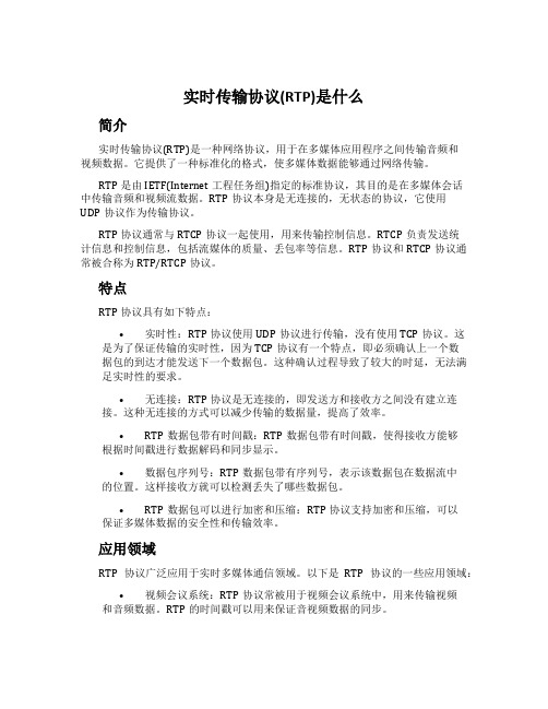
特点RTP协议具有如下特点:•实时性:RTP协议使用UDP协议进行传输,没有使用TCP协议。
这是为了保证传输的实时性,因为TCP协议有一个特点,即必须确认上一个数据包的到达才能发送下一个数据包。
这种确认过程导致了较大的时延,无法满足实时性的要求。
•无连接:RTP协议是无连接的,即发送方和接收方之间没有建立连接。
这种无连接的方式可以减少传输的数据量,提高了效率。
•RTP数据包带有时间戳:RTP数据包带有时间戳,使得接收方能够根据时间戳进行数据解码和同步显示。
•数据包序列号:RTP数据包带有序列号,表示该数据包在数据流中的位置。
这样接收方就可以检测丢失了哪些数据包。
•RTP数据包可以进行加密和压缩:RTP协议支持加密和压缩,可以保证多媒体数据的安全性和传输效率。
应用领域RTP协议广泛应用于实时多媒体通信领域。
以下是RTP协议的一些应用领域:•视频会议系统:RTP协议常被用于视频会议系统中,用来传输视频和音频数据。
RTP的时间戳可以用来保证音视频数据的同步。
•流媒体系统:RTP协议常被用于流媒体系统中,比如实时流媒体直播、点播等。
•视频监控系统:RTP协议能够提供实时的视频流数据传输,可以被用于视频监控系统中,比如公共安全领域的视频监控。
总结RTP协议是一种用于传输音频和视频数据的网络协议,它具有实时性、无连接、数据包带有时间戳和序列号等特点。
- 1、下载文档前请自行甄别文档内容的完整性,平台不提供额外的编辑、内容补充、找答案等附加服务。
- 2、"仅部分预览"的文档,不可在线预览部分如存在完整性等问题,可反馈申请退款(可完整预览的文档不适用该条件!)。
- 3、如文档侵犯您的权益,请联系客服反馈,我们会尽快为您处理(人工客服工作时间:9:00-18:30)。
RCTP实时控制/传输通讯协议
RCTP协议(RealTime Control and Translate Protocol)为自定义实时控制/传输通讯协议。
1、基本帧格式
1.1帧结构
typedef struct
{
uchar head; //帧头
uchar length; //帧长度
uchar length_rep; //帧长度重复
uchar head_rep; //帧头重复
uchar source_id; //发送设备号
uchar directory_id; //接收设备号
uchar handle; //帧与操作类型
uchar parameter[frame_data_size]; //帧参数域buf
uchar AccVal; //累加和校验
uchar stop; //结束符
} struct_frame;
1.2开始符的判断
条件:if(struct_frame.head == struct_frame.head_rep) && (struct_frame.length == struct_frame.length_rep)成立。
1.3帧与操作类型
1.3.1 数据帧的操作类型定义
1.3.2 命令帧的操作类型定义
1.4 校验和
校验和为:0-N的累加值,1字节。
2、基于RCTP的LED数码管数据采集通讯协议: RCTP-Ⅰ协议
RCTP-Ⅰ协议是基于RCTP的LED数码管数据采集通讯协议,物理上基于RS-485口,通过屏蔽双绞线实现通讯。
RCTP-Ⅰ协议是一种主-从协议。
主站设备发送要求到从站设备,从站设备响应,从站不能主动发出信息。
波特率代码表:
在默认状态下通信的设置速率一般是9600、无效验、8数据位、1个停止位。
2.2 操作类型(功能)-共128种
2.3 常用命令与应答
2.3.1 命令—读寄存器数据
例子:主机0X00读从机设备0X02数据请求(读数据):
数据类型:00-十六进制;01-ASCII码
一般主机地址为0x00;止位。
应答:数据帧
2.3.2 命令—写寄存器数据
应答:
2.3.3 命令接收状态回复
当接收命令过程发生异常时回复命令接收状态。
帧与操作类型回复:最高位为0,bit6-bit0原样返回。