数字混合锁相环频率合成器中英文对照外文翻译文献
手机中英文注释
手机中英文注释英文注释A:ADC: 模拟/数字转换ADSL: 不对称数字用户线AFC:自动频率控制AFCDAC:数模转换输出AGC: 自动增益控制AGND:模拟地AID:区域识别标志ALARM: 告警AM: 调幅AMPLIFIER: 放大器AMPS:先进的移动电话系统ANALOG: 模拟ANALOGON:音频逻辑控制启动ANT:天线AOC: 自动输出控制(MOTO专用)APC: 自动功率控制APC:音频处理芯片ARFCH: 绝对信道ASDI:辅助数据输入ASDIFS:辅助数据输入选通ASDCLK:辅助接口时钟信号ASDO:辅助数据输出ASDOFS:辅助数据输出选通ASIC: 专用接口集成电路AST-DET: 饱和度检测AUC:鉴权中心AUX: 辅助AUXADC3:外部AD转换输入3AUXADC4:外部AD转换输入4AUDIO: 音频AVDD:模拟电路供电AFMS(AUDIO FROM MS): 来自手机的音频ATMS(AUDIO TO MS): 去向手机的音频B:BASE: 基极BASE BAND<BB>: 基带BATT-ID:电池类型BATT-TEMP:电池温度BATTP:电池温度测量BBC:基带编解码器BCH: 广播信道BCP:基带串口BDR:语音信道编码信息,接收资料信号BDX:语音信道的编码信息BFRX:控制信道的编码信息,发射同步信号BFSR:音频接收同步信号BFSX:软化射频I/O信号或音频数字信号送CPU BIAS: 偏压BIPOLAR TRANSISTORE: 双极晶体管BIST:内置自测BLUE TOOTH<BT>: 蓝牙BOOT: 屏蔽罩BPF:带通滤通器BREFCAP:基带参考藕合电容BREFOUT:基带参考电压输出BS: 基站BSC: 基站控器BTS: 基站收发器BSCLK:接收时钟信号BSCLK:基带接口时钟信号BSD:接收数字信号BSDI:基带接口数据输入BSDO:接收数字信号BSDO:基带接口数据输出BSDIFS:基带接口数据输入选通BSDOFS:基带接口数据输出选通BSIFS:接收同步信号BSOFS:接收同步信号BSW:频段落选择信号BUS:总线BUZZER:振铃信号C:CAR:电源控制、音频、振铃模块CAPACITY: 电容CCD:电荷耦合器件<即摄像头>CCIO:数据通信器CCIOSW:数据通信口开关CCONTCSX: 维持信号<NOKIA专用>CDMA<CIDE DIVISION MULTIPLE ACCESS>: 码分多址CHARGE<CHRG>:充电CHRGRON:充电启动CHARGEUR:充电电源CHIDENT:充电中断信号CKMIW:时钟和片选信号CLK:时钟信号CLKBM:CPU系统时钟输入CLOCKM:时钟管理CMDDS:测量启动信号CMDCH:充电控制信号CMDVIB:振动控制信号CODEC: 编/译码器COL: 列COLLECTOR: 集电极CONVERTER: 转换器<三星>CONTROL: 控制CPIFSYN:二本振锁相控制信号输出CPRFSYN:一本振锁相控制信号输出CPU< CENTRAL PROCESSING UNIT>: 中央处理器CRYSTAL: 晶体CSLCDGLRESETLCD:用一控制LCD显示CSSRAM:暂存片选信号D:DAI:数字音频接口DATA:数据信号DCS1800M<DIGITAL CELLULAR SYSTEM AT 1800M>: 1800M数字蜂窝系统DCS-SEL:1800MHz频段选择DCT3<DIGITAL CORE TECHNOLOGY 3RD GENERATION>: 第3代数字核心技术DEBUG-RX:调试数据接收DEBUG-TX:调试数据发射DET: 检测.如:SIM-DET.DEMOD:DM: 解调DGND:数字电路地DFMS<DATA FROM MS>;来自手机的数据DIGITL:数字DIODE: 二极管DIPLEXER: 双工器DM-CS: 低通-翻转,片选信号<MOTO专用>DMT:并行多路测试DOMIW:是CPU输出的扫描控制D-REG: 数字调整电压DRAM: 动态存储器DSP<DIGITAL SIGNAL PROCESSOR>: 数字信号处理DSR:测试端口DTMF: 双音多频DTMS<DATA TO MS>: 去向手机的数据DUPLEX: 双工器,即合路器E:EARN:(耳机)负EARP:(耳机)正ECHO CANCEL: 回声抑制功能EFR<ENHANCED FULL RATE>: 扩展的全速率<NOKIA专用>EL<ELECTRO-LUMINESCENT LIGHTING>: 电激发光板<片>.EMC<ELECTROMAGNETIC COMPATIBILITY>: 电磁互换EMI: 电磁干扰EMS: 增强型短信服务<文本+音调+图片+声音+动画>.<比SMS优秀>.EMITTER: 发射极ENRF134:射频频率合成模块启动ENOMEGAMN1:芯片功能启动信号EQUALIZER: 均衡器ESN<ELECTRONIC SN>: 电子序列号.ETACS: 增强型全接入移动通信系统EXC: 外部EXT: 外部F:FACCH: 快速随路控制信道FCH: 频率校正信道FCCH:频率较正信道FDMA<FREQUENCY DIVISION MULTIPLE ADDRESS>: 频分多址FEED-BACK<FDBK>: 反馈FER: 误码率FET<FIELD EFFECT TRANSISTOR>: 场效应管FILTER<FL>: 滤波器FLIP: 翻盖FLOCK:本振锁定控制信号FM: 调频FSK: 移频键控G:GAIN: 增益GMSK: 高斯最小频移键控GPRS<GENERAL PACKET RADIO SERVICE>: 通用无线分组业务GPS:全球导航定位系统GRID: 栅极GSM<GLOBAL SYSTEM FOR MOBILE COMMUNICATIONS>: 全球移动通讯系统.GSM<GLOBAK SYSTEM MOBILE COMMUNICATION>: 900MGSM-SEL:900MHS频段选择信号H:HAMONIC FILTER:谐波滤波器HANDOFF:切换HAND-OFF:越区转接HEAD-INT:耳机请求信号HLR:归属位置寄存器HOOK: 免提HPF:高通滤波器HS<HALF RATE SPEECH>: 半速率I:I: 同相支路IC<INTEGRATED CIRCUIT>: 集成电路IF<INTERMEDIATE FREQUENCY>: 中频IFIN:中频信号输入(正)IFINB:中频信号输入(负)ILLEGAL SOFTWARI LOADED: 非法软件下载IMEI<INTERNATIONAL MOBILE EQUIPMENT IDENTIT中断Y>: 国际移动设备识别码INDUCTANCE: 电感INITIAL:初始INT<INTERRUPT>: 中断INTH:中断管理器INT?C:按键中断判断口INTERFACE: 界面I/O:数据输入/输出IRXP:接收I信号(正)IRXN:接收I信号(负)IRDA<INFRARED RAY>: 红外线ISDN: 综合业务数字网ITXP:发射基带I信号(正)ITXN:发射基带I信号(负)ITWADEVP:时钟(闹钟)开机控制信号IWF:各种业务功能接口J:JACKEN:耳机启动信号K:KEYLIGHT:键盘灯L:LAN<LOCAL AREA NETWORK>: 局域网LANG:低噪声放大器增益控制信号LNAON:低噪声放大器启动信号LCD<LIQUID CRYSTAL DISPLAY>:液晶显示器LE:频率合成器使能信号LED<LIGHT EMITTING DIODE>: 发光二极管LEVEL: 电平LIGHTKEY:按键背景灯控制信号LNA<LOW NOISE AMPLIFIER>: 低噪放大器LOCK: 锁定LOGIC: 逻辑LOOP: 环路LOOP FLITER: 环路滤波器LPF:低通滤波器LSDN<LOCAL SERVICE DIGITAL NETWORK>:本地业务数字网M:MANUAL TEST:人工测试MCLK:主时钟MCU<MICRO CONTROLLER UNIT> : 微处理单元(中央处理器)MDM: 调制/解调器(MOTO专用)MENU: 菜单MESVBATUBAT:测量电压MF: 陶瓷滤波器MIC:麦克风MIDI<MUSICAL INSTRUMENT DIGITAL INTERFACE>: 乐器数字接口MIX1OUT:第一混频器输出(正)MIX1OUTB:第一混频器输出(负)MIX2OUT:第二混频器输出(正常)MIX2OUTB:第二混频器输出(负)MIXIDCSINB:1800MHz混频器输入(负)MIXIDCSIN:1800MHz混频器输入(正)MMS<MULTIMEDIA MESSAGE SERVICE>: 多媒体短消息服务/即彩信<第三代短消息>MMC<MULTIMEDIA CARD>: 多媒体卡MOBILE: 移动MOBILE-SWITCH: 移动交换机MOD: 调制MODEM:调制/解调器MODE:模式MODFREQ:调制菜单MODULATION TYPE:调制类型MP3:MPEG LAYER 3: 一种声音压缩格式,压缩比可达1:12 MPU: 主处理单元MRESPWROIN:CPU上电复位信号输入MSC<MOBILE SEITCH CENTRAL>: 移动交换中心MS<MOBILE SET>: 移动台MSC: 移动交换中心MSIN: 移动台识别码MSK: 最小频移键控MSN: 设备制造号码MSRN: 漫游MUTE: 静音N:NBSSCAX:扫描选择NC: 悬空NEG<NEGATIVE>: 负压NETWORK: 网络O:OCE:使能信号OEL:待机状态下FLASH数据输出使能端OFST: 偏置OLED<ORGANIC LIGHT-EMITTING DIODE>: 有机发光二极管ONSRQ: 免提开关控制OSC:振荡器OSCILLATE: 振荡OUIL:开机信号ONRADIO:控制射频电压产生信号P:PA:功率放大器PA-ON:发射启动信号PA-LEVEL:功率等级信号PAS<PERSONAL ACCSS PHONE SYSTEM>: 无线市话/小灵通/个人通信接入系统PCB: 印刷电路板PCH: 寻呼信道PCHAR:充电维持信号PCM<PULSE CODE MODULATION> : 脉冲编码调制PCN<PERSONAL CIMMUNICATIONS SERVICE>: 个人通信服务(也指其使用的1800M频率)PD/PH/PHD<PHASE DETECTOR>: 鉴相器PDATA: 并行数据PDA<PERSONAL DIGITAL ASSISTANT>: 个人数字助理PHASE: 相位PHS<PERSONAL HANDY-PHONE SYSTEM>: 无线市话/小灵通<日本名称> PIN<PERSONAL IDENTIFICATION NUMBER>: 个人识别码<保存在卡中,错则手机不能使用,允许输错三次> PIN2码用于设定如通话计费等的特殊功能,如被锁住不会影响其他功能的使用.PK PEAK:峰值PLL<PHASE LOCKDE LOOP>: 锁相环PLLOUT:锁相环控制电压输出POLY: 和弦PROTECT: 保护PUK: SIM卡锁的解锁密码. <允许输错10次,错则卡永久报废>PUMP: 激励/泵/电荷泵PVEF:开关机状态寄存器激活信号PWM<PULSE WEIDTH MODULATION> : 脉冲宽度调制PWRON:电源开关PWRHOLD:电源保持PWRKEY:电源健控信号Q:Q: 正交支路QRXP:接收Q信号(正)QRXN:接收Q信号(负)QTXP:发射基带Q信号(正)QTXN:发射基带Q信号(负)QUARTZ CRYSTAL: 石英晶体R:RADIO-TEMP:射频温度检测电路RAMP:功率基准控制信号RECEIVER:听筒信号REED: 干簧管REF: 参考RESCAP:复位信号延时电容RESET:复位RESETLCD:显示屏复位信号RESISTANCE: 电阻RF<RADIO FREQUENCY>: 射频RF-LO:一本振RF-SW:天线开关RF2V8:射频供电2.8VRIF:射频接口功能ROAMING: 漫游ROW: 行RPE-LTP:语音编解码RSLCD:控制LCD对比度的信号RSSI<RECEIVE SIGNAL STRENGTH INDICATION>: 接收场强.接收信号强度指示RTC<REAL TIME CONTROL>: 实时时钟控制RWLCD:显示屏读写控制信号RXD:串行数据接收RXON:接收启动RXIP:接收I信号(正)RXIN:接收I信号(负)RXQP:接收Q信号(正)RXQN:接收Q信号(负)S:SAT-DET<SATURATION>: 饱和度检测SCH: 同步信道SCLEEP E?PROM:码片时钟线SCLI?C:I?C总线时钟线SCOKET: 接口SDAEEP E?PROM:码片数据线SDATA:频率合成器串行数据线SERCLD:去射频时钟线SERDAT:去射频数据线SERIAL: 串行SERVICE LEVEL:服务等级SENSE: 传感器SHIFT: 移相电路SHORTCUT: 短路SIM<SUBSCRIBER IDENTIFY MODULE>: 用户识别模块SIMBAT:SIM 电源SIMGND:SIM卡电路地SIM-I/O:卡数据输入输出信号SIMON:VSIM电源开关SIMPRDG:VSIM 程序控制SIM-RST:SIM卡复位信号SLEEP: 睡眠,休眠SMOC: 数字信号处理器(MOTO专用)SMS<SHORT MESSAGE SERVICE>:短消息SW-VCC:开关供电SPEAKER:喇叭SPI: 串行外围接口SRAM: 静态随机存储器SRAM:暂存器STK<SIM TOOL KIT>: 用户识别应用开发工具STN<SUPER TWISTED NEMATIC>:超扭曲向列型液晶显示屏幕<属反射式LCD,黑暗时清晰度差>STR<START>: 启动信号(如SYN-STR)SWDC: 未调整电压(MOTO专用)SYN<SYNTHESIZER>: (频率)合成SYN-CLK:频率合成时钟信号T:TACS: 全接入移动通信系统TANK: 回路TCH: 话音通道TCXO: 温度补偿型晶振TDMA<TIME DIVISION MULTIPLEX ACCESS>:时分多址TD-SCDMA: 时分同步多址<中国提出的第三代移动通信标准>TEMP: 温度TFD<THIN FILM DIODE>: 薄膜二极管半透式液晶显示器<在反射式/透射式下均能提供高清晰度的显示>TFT<THIN FILM TRANSISTOR>: 薄膜晶体管型液晶显示器<目前最好的>THERM: 温度检测TRANSFER: 转移TSC: 触摸屏TDI-测试信号输入TSO:测试信号输出TCK:测试时钟信号TMS:测试模式控制TXD:串行数据发送TXONPA:发射功放启动TSP:时?串口TAP:测试口TPU:时间处理单元TX:发信TCXO:温度补偿晶体振荡器TS:时隙TEMPRAD:主板温度测量信号TUNING:调谐U:UEM<UNIVERSAL ENERGY MANAGEMENT>: 通用电源管理器<NOKIA专用> UHF: 超高频UI<USER INTERFACE>: 用户模组ULPD:超低功率器件UPDATD: 升级UP-LINK: 上行链路UPP<UNIVERSAL PHONE PROCESSOR>: 通用电话处理器<NOKIA专用>V:VALONVCO:开机维持信号VBATT:电池电压VBC:音频数字信号编解码器VCAP+:升压电容(正)VCAP-:升压电容(负)VCCA:模拟供电VCCCOMP:鉴相器供电VCCPLL:锁相环低噪声放大器供电VCK:音频接收发送的时钟信号VCO<VOLTAGE CONTROLLED OSCILLATOR>: 压控振荡器VCP:语音串行口VCXO<VOLTAGE CONTROLLED CRYSTAL OSCILLATOR>: 压控晶体振荡器VDX:音频发送数据传输信号VDR:音频接口数据传输信号VF: 电池电量检测(三星)VFS:音频数据接收发送选择信号VHF:甚高频VINNORP:音频信号输入正(MIC)VINNORN:音频信号输入负(MIC)VINAUXP:音频信号外部输入正(外部MIC信号)VINAUXN:音频信号外部输入负(外部MIC信号)VOUTNORP:音频信号正输出推动VOUTNORN:音频信号负输出推动VOUTAUXP:音频信号外部耳机正VOUTAUXN:音频信号外部耳机负VPG:LED脉冲激发器VREF:参考电压VREF CAP:参考电压电容耦合VRTC:实时时钟电源VSAUU:开机辅助电压VSCLK:音频接口时钟VSD:发送数字信号VSDI:音频接口选通输入VSDO:音频接口数据输出VSFS:音频接口选通VSFS:发送同步信号VTCXO:主时钟供电W:WAP<WIRELESS APPLICATION PROTOCOL>: 无线应用程序通讯协议WATCH DOG: 看门狗WCDMA<WIDEBAND CODE DIVISION MULTIPLEX ACCESS>: 宽带码分多址<第三代技术>WD-CP: 看门狗脉冲WIRELESS: 无线。
数据通信 毕业论文外文文献英文翻译
郑州轻工业学院本科毕业设计(论文)——英文翻译题目差错控制编码解决加性噪声的仿真学生姓名专业班级通信工程05-2 学号 12院(系)计算机与通信工程学院指导教师完成时间 2009年4月26日英文原文:Data communicationsGildas Avoine and Philippe OechslinEPFL, Lausanne, Switzerlandfgildas.avoine, philippe.oechsling@ep.chAbstractData communications are communications and computer technology resulting from the combination of a new means of communication. To transfer information between the two places must have transmission channel, according to the different transmission media, there is wired data communications and wireless data communications division. But they are through the transmission channel data link terminals and computers, different locations of implementation of the data terminal software and hardware and the sharing of information resources.1 The development of data communicationsThe first phase: the main language, through the human, horsepower, war and other means of transmission of original information.Phase II: Letter Post. (An increase means the dissemination of information)The third stage: printing. (Expand the scope of information dissemination)Phase IV: telegraph, telephone, radio. (Electric to enter the time)Fifth stage: the information age, with the exception of language information, there are data, images, text and so on.1.1 The history of modern data communicationsCommunication as a Telecommunications are from the 19th century, the beginning Year 30. Faraday discovered electromagnetic induction in 1831. Morse invented telegraph in 1837. Maxwell's electromagnetic theory in 1833. Bell invented the telephone in 1876. Marconi invented radio in 1895. Telecom has opened up in the new era. Tube invented in 1906 in order to simulate the development of communications.Sampling theorem of Nyquist criteria In 1928. Shannong theorem in 1948. The invention of the 20th century, thesemiconductor 50, thereby the development of digital communications. During the 20th century, the invention of integrated circuits 60. Made during the 20th century, 40 the concept of geostationary satellites, but can not be achieved. During the 20th century, space technology 50. Implementation in 1963 first synchronized satellite communications. The invention of the 20th century, 60 laser, intended to be used for communications, was not successful. 70 The invention of the 20th century, optical fiber, optical fiber communications can be developed.1.2 Key figuresBell (1847-1922), English, job in London in 1868. In 1871 to work in Boston. In 1873, he was appointed professor at Boston University. In 1875, invented many Telegram Rd. In 1876, invented the telephone. Lot of patents have been life. Yes, a deaf wife.Marconi (1874-1937), Italian people, in 1894, the pilot at his father's estate. 1896, to London. In 1897, the company set up the radio reported. In 1899, the first time the British and French wireless communications. 1916, implementation of short-wave radio communications. 1929, set up a global wireless communications network. Kim won the Nobel Prize. Took part in the Fascist Party.1.3 Classification of Communication SystemsAccording to type of information: Telephone communication system, Cable television system ,Data communication systems.Modulation by sub: Baseband transmission,Modulation transfer.Characteristics of transmission signals in accordance with sub: Analog Communication System ,Digital communication system.Transmission means of communication system: Cable Communications,Twisted pair, coaxial cable and so on.And long-distance telephone communication. Modulation: SSB / FDM. Based on the PCM time division multiple coaxial digital base-band transmission technology. Will gradually replace the coaxial fiber.Microwave relay communications:Comparison of coaxial and easy to set up, low investment, short-cycle. Analog phone microwave communications mainly SSB / FM /FDM modulation, communication capacity of 6,000 road / Channel. Digital microwave using BPSK, QPSK and QAM modulation techniques. The use of 64QAM, 256QAM such as multi-level modulation technique enhance the capacity of microwave communications can be transmitted at 40M Channel 1920 ~ 7680 Telephone Rd PCM figure.Optical Fiber Communication: Optical fiber communication is the use of lasers in optical fiber transmission characteristics of long-distance with a large communication capacity, communication, long distance and strong anti-interference characteristics. Currently used for local, long distance, trunk transmission, and progressive development of fiber-optic communications network users. At present, based on the long-wave lasers and single-mode optical fiber, each fiber road approach more than 10,000 calls, optical fiber communication itself is very strong force. Over the past decades, optical fiber communication technology develops very quickly, and there is a variety of applications, access devices, photoelectric conversion equipment, transmission equipment, switching equipment, network equipment and so on. Fiber-optic communications equipment has photoelectric conversion module and digital signal processing unit is composed of two parts.Satellite communications: Distance communications, transmission capacity, coverage, and not subject to geographical constraints and high reliability. At present, the use of sophisticated techniques Analog modulation, frequency division multiplexing and frequency division multiple access. Digital satellite communication using digital modulation, time division multiple road in time division multiple access.Mobile Communications: GSM, CDMA. Number of key technologies for mobile communications: modulation techniques, error correction coding and digital voice encoding. Data Communication Systems.1.4 Five basic types of data communication system:(1)Off-line data transmission is simply the use of a telephone or similar link to transmit data without involving a computer system.The equipment used at both ends of such a link is not part of a computer, or at least does not immediately make the data available for computer process, that is, the data when sent and / or received are 'off-line'.This type of data communication is relatively cheap and simple.(2)Remote batch is the term used for the way in which data communication technology is used geographically to separate the input and / or output of data from the computer on which they are processed in batch mode.(3)On-line data collection is the method of using communications technology to provide input data to a computer as such input arises-the data are then stored in the computer (say on a magnetic disk) and processed either at predetermined intervals or as required.(4)Enquiry-response systems provide, as the term suggests, the facility for a user to extract information from a computer.The enquiry facility is passive, that is, does not modify the information stored.The interrogation may be simple, for example, 'RETRIEVE THE RECORD FOR EMPLOYEE NUMBER 1234 'or complex.Such systems may use terminals producing hard copy and / or visual displays.(5)Real-time systems are those in which information is made available to and processed by a computer system in a dynamic manner so that either the computer may cause action to be taken to influence events as they occur (for example as in a process control application) or human operators may be influenced by the accurate and up-to-date information stored in the computer, for example as in reservation systems.2 Signal spectrum with bandwidthElectromagnetic data signals are encoded, the signal to be included in the data transmission. Signal in time for the general argument to show the message (or data) as a parameter (amplitude, frequency or phase) as the dependent variable. Signal of their value since the time variables are or not continuous, can be divided into continuous signals and discrete signals; according to whether the values of the dependent variable continuous, can be divided into analog signals and digital Signal.Signals with time-domain and frequency domain performance of the two most basic forms and features. Time-domain signal over time to reflect changing circumstances. Frequency domain characteristics of signals not only contain the same information domain, and the spectrum of signal analysis, can also be a clear understanding of the distribution ofthe signal spectrum and share the bandwidth. In order to receive the signal transmission and receiving equipment on the request channel, Only know the time-domain characteristics of the signal is not enough, it is also necessary to know the distribution of the signal spectrum. Time-domain characteristics of signals to show the letter .It’s changes over time. Because most of the signal energy is concentrated in a relatively narrow band, so most of our energy focused on the signal that Paragraph referred to as the effective band Bandwidth, or bandwidth. Have any signal bandwidth. In general, the greater the bandwidth of the signal using this signal to send data Rate on the higher bandwidth requirements of transmission medium greater. We will introduce the following simple common signal and bandwidth of the spectrum.More or less the voice signal spectrum at 20 Hz ~ 2000 kHz range (below 20 Hz infrasound signals for higher than 2000 KHz. For the ultrasonic signal), but with a much narrower bandwidth of the voice can produce an acceptable return, and the standard voice-frequency signal gnal 0 ~ 4 MHz, so the bandwidth of 4 MHz.As a special example of the monostable pulse infinite bandwidth. As for the binary signal, the bandwidth depends on the generalThe exact shape of the signal waveform, as well as the order of 0,1. The greater the bandwidth of the signal, it more faithfully express the number of sequences.3 The cut-off frequency channel with bandwidthAccording to Fourier series we know that if a signal for all frequency components can be completely the same through the transmission channel to the receiving end, then at the receiving frequency components of these formed by stacking up the signal and send the signal side are exactly the same, That is fully recovered from the receiving end of the send-side signals. But on the real world, there is no channel to no wear and tear through all the Frequency components. If all the Fourier components are equivalent attenuation, then the signal reception while Receive termination at an amplitude up Attenuation, but the distortion did not happen. However, all the transmission channel and equipment for different frequency components of the degree of attenuation is differentSome frequency components almost no attenuation, and attenuation of some frequency components by anumber, that is to say, channel also has a certain amount of vibrationIncrease the frequency characteristics, resulting in output signal distortion. Usually are frequency of 0 Hz to fc-wide channel at Chuan harmonic lost during the attenuation does not occur (or are a very small attenuation constant), whereas in the fc frequency harmonics at all above the transmission cross Decay process a lot, we put the signal in the transmission channel of the amplitude attenuation of a component to the original 0.707(that is, the output signal Reduce by half the power) when the frequency of the corresponding channel known as the cut-off frequency (cut - off frequency).Cut-off frequency transmission medium reflects the inherent physical properties. Other cases, it is because people interested in Line filter is installed to limit the bandwidth used by each user. In some cases, because of the add channel Two-pass filter, which corresponds to two-channel cut-off frequency f1 and f2, they were called up under the cut-off frequency and the cut-off frequency.This difference between the two cut-off frequency f2-f1 is called the channel bandwidth. If the input signal bandwidth is less than the bandwidth of channel, then the entire input signal Frequency components can be adopted by the Department of channels, which the letter Road to be the output of the output waveform will be true yet. However, if the input signal bandwidth greater than the channel bandwidth, the signal of a Frequency components can not be more on the channel, so that the signal output will be sent with the sending end of the signal is somewhat different, that is produced Distortion. In order to ensure the accuracy of data transmission, we must limit the signal bandwidth.4 Data transfer rateChannel maximum data transfer rate Unit time to be able to transfer binary data transfer rate as the median. Improve data transfer rate means that the space occupied by each Reduce the time that the sequence of binary digital pulse will reduce the cycle time, of course, will also reduce the pulse width.The previous section we already know, even if the binary digital pulse signal through a limited bandwidth channel will also be the ideal generated wave Shape distortion, and when must the input signal bandwidth, the smaller channel bandwidth, output waveformdistortion will be greater. Another angle Degree that when a certain channel bandwidth, the greater the bandwidth of the input signal, the output signal the greater the distortion, so when the data transmissionRate to a certain degree (signal bandwidth increases to a certain extent), in the on-channel output signal from the receiver could not have been Distortion of the output signal sent to recover a number of sequences. That is to say, even for an ideal channel, the limited bandwidth limit System of channel data transfer rate.At early 1924, H. Nyquist (Nyquist) to recognize the basic limitations of this existence, and deduced that the noise-free Limited bandwidth channel maximum data transfer rate formula. In 1948, C. Shannon (Shannon) put into the work of Nyquist 1 Step-by-step expansion of the channel by the random noise interference. Here we do not add on to prove to those now seen as the result of a classic.Nyquist proved that any continuous signal f (t) through a noise-free bandwidth for channel B, its output signal as a Time bandwidth of B continuous signal g (t). If you want to output digital signal, it must be the rate of g (t) for interval Sample. 2B samples per second times faster than are meaningless, because the signal bandwidth B is higher than the high-frequency component other than a letter has been Road decay away. If g (t) by V of discrete levels, namely, the likely outcome of each sample for the V level of a discrete one, The biggest channel data rate Rm ax as follows:Rmax = 2Blog 2 V (bit / s)For example, a 3000 Hz noise bandwidth of the channel should not transmit rate of more than 6,000 bits / second binary digital signal.In front of us considered only the ideal noise-free channel. There is noise in the channel, the situation will rapidly deteriorate. Channel Thermal noise with signal power and noise power ratio to measure the signal power and noise power as the signal-to-noise ratio (S ignal - to -- Noise Ratio). If we express the signal power S, and N express the noise power, while signal to noise ratio should be expressed as S / N. However, people Usually do not use the absolute value of signal to noise ratio, but the use of 10 lo g1 0S / N to indicate the units are decibels (d B). For the S / N equal 10 Channel, said its signal to noise ratio for the 1 0 d B; the same token, if the channel S / N equal to one hundred, then the signal to noiseratio for the 2 0 d B; And so on. S hannon noise channel has about the maximum data rate of the conclusions are: The bandwidth for the BH z, signal to noise ratio for the S / N Channel, the maximum data rate Rm ax as follows:Rmax = Blog 2 (1 + S / N) (bits / second)For example, for a bandwidth of 3 kHz, signal to noise ratio of 30 dB for the channel, regardless of their use to quantify the number of levels, nor Fast sampling rate control, the data transfer rate can not be greater than 30,000 bits / second. S h a n n o n the conclusions are derived based on information theory Out for a very wide scope, in order to go beyond this conclusion, like you want to invent perpetual motion machine, as it is almost impossible.It is worth noting that, S hannon conclusions give only a theoretical limit, and in fact, we should be pretty near the limit Difficult.SUMMARYMessage signals are (or data) of a magnetic encoder, the signal contains the message to be transmitted. Signal according to the dependent variable Whether or not a row of values, can be classified into analog signals and digital signals, the corresponding communication can be divided into analog communication and digital communication.Fourier has proven: any signal (either analog or digital signal) are different types of harmonic frequencies Composed of any signal has a corresponding bandwidth. And any transmission channel signal attenuation signals will, therefore, Channel transmission of any signal at all, there is a data transfer rate limitations, and this is Chengkui N yquist (Nyquist) theorem and S hannon (Shannon) theorem tells us to conclusions.Transmission medium of computer networks and communication are the most basic part of it at the cost of the entire computer network in a very Large proportion. In order to improve the utilization of transmission medium, we can use multiplexing. Frequency division multiplexing technology has many Road multiplexing, wave division multiplexing and TDM three that they use on different occasions.Data exchange technologies such as circuit switching, packet switching and packetswitching three have their respective advantages and disadvantages. M odem are at Analog phone line for the computer's binary data transmission equipment. Modem AM modulation methods have, FM, phase modulation and quadrature amplitude modulation, and M odem also supports data compression and error control. The concept of data communications Data communication is based on "data" for business communications systems, data are pre-agreed with a good meaning of numbers, letters or symbols and their combinations.参考文献[1]C.Y.Huang and A.Polydoros,“Two small SNR classification rules for CPM,”inProc.IEEE Milcom,vol.3,San Diego,CA,USA,Oct.1992,pp.1236–1240.[2]“Envelope-based classification schemes for continuous-phase binary Frequency-shift-keyed modulations,”in Pr oc.IEEE Milcom,vol.3,Fort Monmouth,NJ,USA,Oct.1994,pp. 796–800.[3]A.E.El-Mahdy and N.M.Namazi,“Classification of multiple M-ary frequency-shift keying over a rayleigh fading channel,”IEEE m.,vol.50,no.6,pp.967–974,June 2002.[4]Consulative Committee for Space Data Systems(CCSDS),Radio Frequency and Modulation SDS,2001,no.401.[5]E.E.Azzouz and A.K.Nandi,“Procedure for automatic recognition of analogue and digital modulations,”IEE mun,vol.143,no.5,pp.259–266,Oct.1996.[6]A.Puengn im,T.Robert,N.Thomas,and J.Vidal,“Hidden Markov models for digital modulation classification in unknown ISI channels,”in Eusipco2007,Poznan,Poland, September 2007,pp.1882–1885.[7]E.Vassalo and M.Visintin,“Carrier phase synchronization for GMSK signals,”I nt.J.Satell. Commun.,vol.20,no.6,pp.391–415,Nov.2002.[8]J.G.Proakis,Digital Communications.Mc Graw Hill,2001.[9]L.Rabiner,“A tutorial on hidden Markov models and selected applications in speechrecognition,”Proc.IEEE,vol.77,no.2,pp.257–286,1989.英文译文:数据通信Gildas Avoine and Philippe OechslinEPFL, Lausanne, Switzerlandfgildas.avoine, philippe.oechsling@ep.ch摘要数据通信是通信技术和计算机技术相结合而产生的一种新的通信方式。
基于NE564D锁相环频率合成器的设计
基于NE564D锁相环频率合成器的设计The Design of PLL Frequency Synthesizer Based on NE564D曾素琼(嘉应学院电子信息工程学院,广东梅州514015)Zeng Su-qiong(School of Electronics and Information Engineer, Jiaying University,Guangdong Meizhou 514015)摘要:设计基于NE564D的锁相频率合成器,对系统的实现作了详细描述,最后对系统作了实验验证及分析。
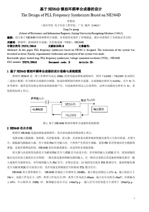
关键词:锁相环;锁相频率合成器;压控振荡器(VCO);NE564D中图分类号:TP273;TN915 文献标识码:B 文章编号:Abstract: In this paper, PLL frequency synthesizer based on NE564 is designed. The realization of the system was described in detail. Finally, experimental verification and analyzed of the system were made.Keywords: phase-locked loop; PLL frequency synthesizer; voltage-controlled oscillator (VCO);NE564DCLC number: TP273;TN915 Document code: B Article ID:1基于NE564D锁相环频率合成器的设计思路与系统框图锁相环NE564D是一种工作频率可高达50MHz的常用超高频集成锁相环,利用74LS393(74LS393是双四位二进制计数器)作为频率合成器的分频器,组成倍频锁相环频率合成器。
合成器输出频率为fo=Nfr。
式中fr为参考频率,通常是用高稳定度的晶体振荡器产生,对晶振频率固定之后获得的。
手机测试常用词汇的中英文对照[1](1)
](https://uimg.taocdn.com/6f54037025c52cc58bd6be46.webp)
polyphonic ringtone和弦铃声chord music ringtone 对讲机Walkie-Talkie全球定位系统GPS (Global Positioning System)高保彩铃真high fidelity(常简写为hi-fi)移动梦网Monternet(Mobile+Internet)短信服务SMS(Short Message Service)彩信服务MMS(Multimedia Message service)客户身份识别卡SIM卡(Subscriber Identity Module)全球移动通信系统GSM (Global System For Mobile Communications) 储值卡pre-paid phone card语音提示voice prompt直板手机bar phone翻盖手机clamshell phone /flip phone滑盖手机slide phone翻盖接听flip answer按键keypad按键音keypad tone提示音warning tone手机充值cellular phone replenishing/recharging手机入网费initiation charges for mobile phone; mobile access fee漫游roaming service手机用户mobile phone user/subscriber短信short message; text message图片短信picture message手机费mobile phone fee关机power off手机铃音mobile phone ringtone振动vibrate手机实名制mobile phone identification policy双向收费two-way charging scheme彩屏color screen壁纸wallpaper待机模式standby mode操作菜单options菜单模式list view/ grid view快捷图标short-cut icon自动重拨automatic redial快速拨号speed dial语音拨号voice dial任意键应答any key answer限制呼叫fixed dial呼出通话outgoing call被叫通话incoming call近来的呼叫recent call呼叫转移call divert未接电话missed call已接电话received call不在服务区out of reach手机电路中常用的中英文对照A/D:模数转换。
基于集成频率合成器的锁相环设计
与
法 | 蔫
l l 。
第 日 月 己口 年1 口
己卷 第 1 7 期
基 于 集成 频 率合 成 器 的锁 相 环 设计
郝 绍 杰
( 中国电子科技集 团公 司第 4 究所 1研
青 岛 265) 6 5 5
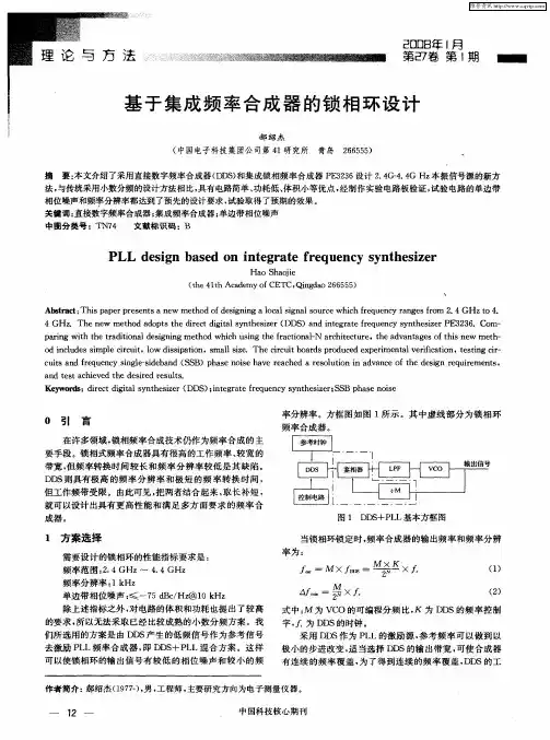
摘 要: 本文介绍 了采用 直接数字频率 合成器 ( D ) D S 和集成锁相频 率合成 器 P 33 设计 2 4 - 4 本 振信号源 的新方 E 26 .G4 G Hz . 法, 与传统采用小数分频 的设计 方法相 比, 有电路 简单 、 具 功耗 低 、 体积小 等优点 , 经制作 实验 电路 板验证 , 试验 电路 的单 边带 相位噪声和频率 分辨率都达到 了预先 的设计要求 , 试验取得 了预期 的效果 。
们所选 用 的方案 是 由 D S产生 的低 频信 号作 为参 考信 号 D
式 中 : 为 V O的可 编程 分频 比 , 为 D S的频 率 控 制 M C K D 字 , 为 D S的时钟 。 D 采用 D S D 作为 P L的激励源 , L 参考频率可以做到以
去激励 P L频率合成器 , D S L L 即 D +P L混合方案。这样 可 以使 锁相 环 的输 出信 号 有较 低 的相 位 噪 声 和较 小 的频
c lsa d fe u n y sn l-ie a d( SB)p a e n ieh v e c e e ou in i d a c ft ed sgn r q ie n s ut n rq e c i esd b n S g h s os a e r a h d a r s l to n a v n eo h e i e u r me t ,
0 引 言
在许多领域 , 锁相频率合成技术仍作为频率合成 的主
高速数字混合锁相环频率合成器毕业论文中英文资料对照外文翻译文献综述
中英译文翻译英文:High Speed Digital Hybrid PLL Frequency Synthesizer译文:高速数字混合锁相环频率合成器To get the high-speed, it is necessary to prepare the precise synchronization of the complicated design.In 2001, H. G. Ryu proposed a simplified structure of the DDFS (direct digital frequency synthesizer)-driven PLL for the high switching speed [2].However, there is a problem that the speed of the whole system is limited by PLL.Y. Fouzar proposed a PLL frequency synthesizer of dual loop configuration using frequency-to-voltage converter (FVC) [3].It has a fast switching speed by the PD (phase detector), FVC using output signal of VCO and the proposed coarse tuning controller.However, H/W complexity is increased for the high switching speed.Also, it shows the fast switching characteristic only when the FVC works well.Another method is pre-tuning one which is called DH-PLL in this study [4].It has very high speed switching property, but H/W complexity and power consumption are increased due to digital look-up table (DLT) which is usually implemented by the ROM including the transfer characteristic ofVCO(voltage controlled oscillator).For this reason, this paper proposes a timing synchronization circuit for the rapid frequency synthesis and a very simple DLT replacement digital logic block instead of the complex ROM type DLT for high speed switching and low power consumption. Also, the requisite condition is solved in the proposed method. The fast switching operation at every the frequency synthesis process is verified by the computer circuit simulation.II.DH-PLL synthesizerAs shown in Fig.1, the open-loop synthesizer is a direct frequency synthesis type that VCO 要得到高运行速度,事先做好复杂设计的精确同步是必要的。
基于数字锁相环的宽带频率源设计
Ke r s f e u n y s n h sz r d g t l h s o k d l o ;n e r t d p a e l c e o p y wo d :r q e c y t e i ; i ia a e l c e o p i t g a e h s o k d l o e p
( 舶 重 工集 团公 司 7 3所 , 州 2 5 0 ) 船 2 扬 2 0 1
摘要 : 介绍了数字锁相环路的基本原理 , 分析了集成锁相环芯片 A F 17 D 40 的性 能 , 采用其设计 出一种具有多个频道
的 宽 带频 率 合 成 器 , 具 有 结 构 简 单 、 定 性 好 、 度 高 、 实 现 等 特 点 。 它 稳 精 易
出宽带、 低相噪的频率合成器。
1 锁 相 环 频 率 合 成 器 原 理
锁 相 环路基 本 的方框 图如 图 1 示 所
f f
。
.
—
.ቤተ መጻሕፍቲ ባይዱ
.
.
—
—
—
.
—
—
.
图 1 锁 相 环 基 本 框 图
高精 度参 考 品振 的信号 上 , 因此 具有频 带 宽 、 作频 工
率高、 频谱 质 量好 等优 点 ; 其 不足之 处 是频率 分 辨 但 率 、 率建 立时 间等 方 面 远 不如 直 接 式 数 字 频 率合 频 成 器 。而且 大规模 集 成 电路 技术 的迅速 发展及 广 泛 应 用改 变 了传统 的模 拟 电路 设 计 方 法 , 因此 数 字 锁
0 引 言
随着 雷 达 技术 的不 断 发展 , 频 率 合 成器 的频 对 率稳 定度 、 频谱 纯度 、 率范 围 以及 捷 变频 速度 提 出 频 了更 高要 求 。频率 合 成 有 很 多方 式 , 接模 拟 频 率 直
手机维修中英文对照表第一版
A ampere 安培A /D 模拟/数字信号转换A/D analog/digital 模拟/数字A/D 模拟接口A/LB 音频/逻辑版AIL-IN 输入到左声道耳机放大器AIL-IN 中断信号输入【检测耳机是否接入】AIL-OUT 左声道耳机放大信号输入A20/ECLK 地址线第二十位AB address bus 地址总线AB-SEL 输入端口选择信号Action 行动Acting-deae 假运行模式Activate 激活Activate 启动Activate filter 有缘滤波器ADO 转换电池,判断电量ADI 转换电池,判断电量AD 美国模拟器件芯片生产标识ADAC 模/数转化器ADAC 捕助数/模转换器ADC 模/数转化器ADC-ON 模数转换器开启ADD 地址Add entry 加项Add networkto list 向目录增加网络Addition adjacent 邻近Address in formation地址信息Aadjacent cell monitoring邻近蜂窝监测Adjust ring volume调整振铃音量ADP自动数据处理ADPCM 自适应差分脉码调制ADTRIG 模拟转化触发信号AF audio frequency音频AEC自动频率控制AFCOUT自动频率控制信号输入AFMS音频线路板AG and gate 与门ACC自动增益控制ACC-EN 自动增益控制使能AGCH 准予接入信道Agenda 备忘录AGND 模拟地AGNDAI 接地AID 区域识别标志Air ime 通话时间Air 具ime counter通话计时器AIS ALC警告指示信息Alarm闹钟Alarms 警告音LIC 自动电平控制Alcohol 酒精Alcohol bottle 酒精瓶Alert提示Alert振铃驱动ALEV auto level 自动电平All calls 所有通话ALOC接入果荷等级ALRT-MICN 反相辅助音频信号输入ALRT-REF振铃放大器的非反方向输入ALRT-VCC振铃/耳机放大器电源ALRTIN 振铃放大器的反相输入ALRTOUTP 振铃放大器的非反相输入AM 调幅AM-ADJ 幅度调整AMP amplifier放大器Amplification 放大倍数Amplifying tube放大管AMPS先进的移动电话系统ANA-CLK多模同步时钟ANA-STR多模开启And logic qperation与运算Anode阳极。
IIR数字滤波器中英文对照外文翻译文献
(文档含英文原文和中文翻译)中英文资料对照外文翻译IIR Digital Filter DesignAn important step in the development of a digital filter is the determination of a realizable transfer function G(z) approximating the given frequency response specifications. If an IIR filter is desired,it is also necessary to ensure that G(z) is stable. The process of deriving the transfer function G(z) is called digital filter design. After G(z) has been obtained, the next step is to realize it in the form of a suitable filter structure. In chapter 8,we outlined a variety of basic structures for the realization of FIR and IIRtransfer functions. In this chapter,we consider the IIR digital filter design problem. The design of FIR digital filters is treated in chapter 10.First we review some of the issues associated with the filter design problem. A widely used approach to IIR filter design based on the conversion of a prototype analog transfer function to a digital transfer function is discussed next. Typical design examples are included to illustrate this approach. We then consider the transformation of one type of IIR filter transfer function into another type, which is achieved by replacing the complex variable z by a function of z. Four commonly used transformations are summarized. Finally we consider the computer-aided design of IIR digital filter. To this end, we restrict our discussion to the use of matlab in determining the transfer functions.9.1 preliminary considerationsThere are two major issues that need to be answered before one can develop the digital transfer function G(z). The first and foremost issue is the development of a reasonable filter frequency response specification from the requirements of the overall system in which the digital filter is to be employed. The second issue is to determine whether an FIR or IIR digital filter is to be designed. In the section ,we examine these two issues first . Next we review the basic analytical approach to the design of IIR digital filters and then consider the determination of the filter order that meets the prescribed specifications. We also discuss appropriate scaling of the transfer function.9.1.1 Digital Filter SpecificationsAs in the case of the analog filter,either the magnitude and/or the phase(delay) response is specified for the design of a digital filter for most applications. In some situations, the unit sample response or step response may be specified. In most practical applications, the problem of interest is the development of a realizable approximation to a given magnitude response specification. As indicated in section 4.6.3, the phase response of the designed filter can be corrected by cascading it with an allpass section. The designof allpass phase equalizers has received a fair amount of attention in the last few years. We restrict our attention in this chapter to the magnitude approximation problem only. We pointed out in section 4.4.1 that there are four basic types of filters,whose magnitude responses are shown in Figure 4.10. Since the impulse response corresponding to each of these is noncausal and of infinite length, these ideal filters are not realizable. One way of developing a realizable approximation to these filter would be to truncate the impulse response as indicated in Eq.(4.72) for a lowpass filter. The magnitude response of the FIR lowpass filter obtained by truncating the impulse response of the ideal lowpass filter does not have a sharp transition from passband to stopband but, rather, exhibits a gradual "roll-off."Thus, as in the case of the analog filter design problem outlined in section 5.4.1, the magnitude response specifications of a digital filter in the passband and in the stopband are given with some acceptable tolerances. In addition, a transition band is specified between the passband and the stopband to permit the magnitude to drop off smoothly. For example, the magnitude )(ωj e G of a lowpass filter may be given as shown in Figure7.1. As indicated in the figure, in the passband defined by 0p ωω≤≤, we require that the magnitude approximates unity with an error of p δ±,i.e.,p p j p for e G ωωδδω≤+≤≤-,1)(1.In the stopband, defined byπωω≤≤s ,we require that the magnitude approximateszero with an error of i s ,δ.e., ,)(s j e G δω≤ for πωω≤≤s .The frequencies p ω and s ω are , respectively, called the passband edge frequency and the stopband edge frequency. The limits of the tolerances in the passband and stopband,p δ and s δ, are usually called the peak ripple values. Note that the frequency response )(ωj e G of a digital filter is a periodic function of ω,and the magnitude response of a real-coefficient digital filter is an even function ofω. As a result, the digital filter specifications are given only for the range πω≤≤0.Digital filter specifications are often given in terms of the loss function,)(log 20)(10ωωζj e G -=, in dB. Here the peak passband ripple p α and theminimum stopband attenuation s α are given in dB,i.e., the loss specifications of a digital filter are given bydB p p )1(log 2010δα--=,dB s s )(log 2010δα-=. 9.1 Preliminary ConsiderationsAs in the case of an analog lowpass filter, the specifications for a digital lowpass filter may alternatively be given in terms of its magnitude response, as in Figure 7.2. Here the maximum value of the magnitude in the passband is assumed to be unity, and the maximum passband deviation, denoted as 1/21ε+,is given by the minimum value of the magnitude in the passband. The maximum stopband magnitude is denoted by 1/A.For the normalized specification, the maximum value of the gain function or the minimum value of the loss function is therefore 0 dB. The quantitymax α given bydB )1(log 20210max εα+= Is called the maximum passband attenuation. Forp δ<<1, as is typically the case, it can be shown thatp p αδα2)21(log 2010max ≅--≅The passband and stopband edge frequencies, in most applications, are specified in Hz, along with the sampling rate of the digital filter. Since all filter design techniques are developed in terms of normalized angular frequencies p ω and s ω,the sepcified critical frequencies need to be normalized before a specific filter design algorithm can be applied. Let T F denote the sampling frequency in Hz, and F P and F s denote, respectively,the passband and stopband edge frequencies in Hz. Then the normalized angular edge frequencies in radians are given byT F F F F p Tp T p p ππω22==Ω=T F F F F s Ts T s s ππω22==Ω= 9.1.2 Selection of the Filter Type The second issue of interest is the selection of the digital filter type,i.e.,whether an IIR or an FIR digital filter is to be employed. The objective of digital filter design is to develop a causal transfer function H(z) meeting the frequency response specifications. ForIIR digital filter design, the IIR transfer function is a real rational function of 1-z .H(z)=NMdNz z d z d d pMz z p z p p ------++++++++......2211022110 Moreover, H(z) must be a stable transfer function, and for reduced computational complexity, it must be of lowest order N. On the other hand, for FIR filter design, the FIRtransfer function is a polynomial in 1-z :∑=-=N n n zn h z H 0][)(For reduced computational complexity, the degree N of H(z) must be as small as possible. In addition, if a linear phase is desired, then the FIR filter coefficients must satisfy the constraint:][][N n h n h -±=T here are several advantages in using an FIR filter, since it can be designed withexact linear phase and the filter structure is always stable with quantized filter coefficients. However, in most cases, the order N FIR of an FIR filter is considerably higher than the order N IIR of an equivalent IIR filter meeting the same magnitude specifications. In general, the implementation of the FIR filter requires approximately N FIR multiplications per output sample, whereas the IIR filter requires 2N IIR+1 multiplications per output sample. In the former case, if the FIR filter is designed with a linear phase, then the number of multiplications per output sample reduces to approximately (N FIR+1)/2. Likewise, most IIR filter designs result in transfer functions with zeros on the unit circle,N with all of the zeros on the unit and the cascade realization of an IIR filter of orderIIRN+3)/2] multiplications per output sample. It has been shown that circle requires [(3IIRfor most practical filter specifications, the ratio N FIR/N IIR is typically of the order of tens or more and, as a result, the IIR filter usually is computationally more efficient[Rab75]. However ,if the group delay of the IIR filter is equalized by cascading it with an allpass equalizer, then the savings in computation may no longer be that significant [Rab75]. In many applications, the linearity of the phase response of the digital filter is not an issue,making the IIR filter preferable because of the lower computational requirements.9.1.3 Basic Approaches to Digital Filter DesignIn the case of IIR filter design, the most common practice is to convert the digital filter specifications into analog lowpass prototype filter specifications, and then to transform it into the desired digital filter transfer function G(z). This approach has been widely used for many reasons:(a) Analog approximation techniques are highly advanced.(b) They usually yield closed-form solutions.(c) Extensive tables are available for analog filter design.(d) Many applications require the digital simulation of analog filters.In the sequel, we denote an analog transfer function as)()()(s D s P s H a a a =, Where the subscript "a" specifically indicates the analog domain. The digital transfer function derived form H a (s) is denoted by)()()(z D z P z G = The basic idea behind the conversion of an analog prototype transfer function H a (s) into a digital IIR transfer function G(z) is to apply a mapping from the s-domain to the z-domain so that the essential properties of the analog frequency response are preserved. The implies that the mapping function should be such that(a) The imaginary(j Ω) axis in the s-plane be mapped onto the circle of the z-plane.(b) A stable analog transfer function be transformed into a stable digital transfer function.To this end,the most widely used transformation is the bilinear transformation described in Section 9.2.Unlike IIR digital filter design,the FIR filter design does not have any connection with the design of analog filters. The design of FIR filter design does not have any connection with the design of analog filters. The design of FIR filters is therefore based on a direct approximation of the specified magnitude response,with the often added requirement that the phase response be linear. As pointed out in Eq.(7.10), a causal FIR transfer function H(z) of length N+1 is a polynomial in z -1 of degree N. The corresponding frequency response is given by∑=-=N n n j j en h e H 0][)(ωω.It has been shown in Section 3.2.1 that any finite duration sequence x[n] of length N+1 is completely characterized by N+1 samples of its discrete-time Fourier transfer X(ωj e ). As a result, the design of an FIR filter of length N+1 may be accomplished by finding either the impulse response sequence {h[n]} or N+1 samples of its frequency response )H(e j ω. Also,to ensure a linear-phase design, the condition of Eq.(7.11) must be satisfied. Two direct approaches to the design of FIR filters are the windowed Fourier series approach and the frequency sampling approach. We describe the former approach in Section 7.6. The second approach is treated in Problem 7.6. In Section 7.7 we outline computer-based digital filter design methods.作者:Sanjit K.Mitra国籍:USA出处:Digital Signal Processing -A Computer-Based Approach 3eIIR数字滤波器的设计在一个数字滤波器发展的重要步骤是可实现的传递函数G(z)的接近给定的频率响应规格。
锁相环频率合成器
锁相环频率合成器介绍锁相环频率合成器(Phase Locked Loop Frequency Synthesizer)是一种广泛应用于电子通信、无线电设备和测量仪器中的电路。
它主要用于产生稳定且精确的输出频率信号,可以将输入信号的频率放大、分频或合成,以满足不同应用的需求。
原理锁相环频率合成器的基本原理是通过负反馈控制,将输出频率与参考频率(或参考信号)比较,然后通过调整VCO(Voltage Controlled Oscillator,电压控制振荡器)的控制电压,使其输出频率与参考频率保持同步。
简单来说,锁相环频率合成器就是将输入信号锁定到某个特定的频率上。
组成部分锁相环频率合成器由多个部分组成,包括相位比较器、环路滤波器、VCO和分频器。
相位比较器(Phase Comparator)相位比较器用于比较参考信号的相位与VCO输出信号的相位之间的差异,并产生一个误差信号。
常见的相位比较器有模型相位比较器和数字相位比较器。
环路滤波器(Loop Filter)环路滤波器用于滤波和增益控制,将相位比较器输出的误差信号转换为VCO控制电压。
环路滤波器的特性会影响系统的稳定性和锁定时间。
VCO(Voltage Controlled Oscillator)VCO是锁相环频率合成器的核心组件,它根据控制电压的变化来产生不同频率的输出信号。
VCO的输出频率与输入的控制电压成正比。
分频器(Divider)分频器用于降低输出频率。
在一些应用中,需要将VCO的高频输出信号分频得到稳定的低频信号。
工作原理锁相环频率合成器的工作过程可以分为以下几个步骤:1.参考信号与VCO输出信号经过相位比较器进行相位比较。
2.相位比较器产生误差信号,通过环路滤波器转换为控制电压。
3.控制电压作用于VCO,使其输出频率发生变化。
4.VCO输出信号经过分频器得到稳定的输出信号。
5.输出信号经过反馈回到相位比较器,与参考信号进行相位比较。
6.如果相位比较器检测到相位差异,则通过反馈机制调整控制电压,使输出频率与参考频率保持同步。
- 1、下载文档前请自行甄别文档内容的完整性,平台不提供额外的编辑、内容补充、找答案等附加服务。
- 2、"仅部分预览"的文档,不可在线预览部分如存在完整性等问题,可反馈申请退款(可完整预览的文档不适用该条件!)。
- 3、如文档侵犯您的权益,请联系客服反馈,我们会尽快为您处理(人工客服工作时间:9:00-18:30)。
中英文对照外文翻译文献
英文:High Speed Digital Hybrid PLL Frequency Synthesizer
译文:高速数字混合锁相环频率合成器
To get the high-speed, it is necessary to prepare the precise synchronization of the complicated design.
In 2001, H. G. Ryu proposed a simplified structure of the DDFS (direct digital frequency synthesizer)-driven PLL for the high switching speed [2].
However, there is a problem that the speed of the whole system is limited by PLL.
Y. Fouzar proposed a PLL frequency synthesizer of dual loop configuration using frequency-to-voltage converter (FVC) [3].
It has a fast switching speed by the PD (phase detector), FVC using output signal of VCO and the proposed coarse tuning controller.
However, H/W complexity is increased for the high switching speed.
Also, it shows the fast switching characteristic only when the FVC works well.
Another method is pre-tuning one which is called DH-PLL in this study [4].
It has very high speed switching property, but H/W complexity and power consumption are increased due to digital look-up table (DLT) which is usually implemented by the ROM including the transfer characteristic of
VCO(voltage controlled oscillator).
For this reason, this paper proposes a timing synchronization circuit for the rapid frequency synthesis and a very simple DLT replacement digital logic block instead of the complex ROM type DLT for high speed switching and low power consumption. Also, the requisite condition is solved in the proposed method. The fast switching operation at every the frequency synthesis process is verified by the computer circuit simulation.
II.DH-PLL synthesizer
As shown in Fig.1, the open-loop synthesizer is a direct frequency synthesis type that VCO 要得到高运行速度,事先做好复杂设计的精确同步是必要的。
2001年,H.G.Ryu提出了一种简化结构的直接数字频率合成器(DDFS)驱动的高转换速度锁相环【2】。
但是,有一个问题,整个系统的速度是受锁相环限制的。
Y.Fouzar提出了一种使用频率—电压转换器(FVC)具有双重回路结构的锁相环频率合成器【3】。
因为鉴相器(PD), FVC利用了压控振荡器的输出信号和我们提出的粗调控制器,所以它具有快速切换速度。
但是,因为有高速系统转换速度使得H / W的复杂性增加了。
另外,结果表明只有FVC工作状态良好时系统才有较高切换速度。
另一种方法是做预先调整也就是本项研究中的DH-PLL 【4】。
它具有高速切换的特性,但是因为数字查找表(DLT)的原因,H / W复杂度和功耗明显增大了,因为DLT 经常被ROM执行,DLT中包含压控振荡器(VCO)的传输特性。
介于以上原因, 为得到较高切换速度和低功耗,本文提出了一种新的快速定时同步频率合成电路,用一个非常简单的DLT替代数字逻辑块,而不用复杂的ROM型(DLT)。
同时,在该方法中所需必要条件也解决了,频率合成过程的高切换速度在计算机电路仿真中已经得到验证了。
2.DH-PLL合成器
图1中所示的开环频率合成技术是一种直接频率合成方式,在频率控
desired VCO frequency.
③is fixed until a new FCW is made. 关系是固定的。
表1 仿真参数。