可迅速布置的机械手系统大学毕业论文外文文献翻译及原文
机械手外文翻译 修改版
密级分类号编号成绩本科生毕业设计 (论文)外文翻译原文标题Simple Manipulator And The Control Of It 译文标题简易机械手及控制作者所在系别机械工程系作者所在专业xxxxx作者所在班级xxxxxxxx作者姓名xxxx作者学号xxxxxx指导教师姓名xxxxxx指导教师职称副教授完成时间2012 年02 月北华航天工业学院教务处制译文标题简易机械手及控制原文标题 Simple Manipulator And The Control Of It作者机电之家译名JDZJ国籍中国原文出处机电之家中文译文:简易机械手及控制随着社会生产不断进步和人们生活节奏不断加快,人们对生产效率也不断提出新要求。
由于微电子技术和计算软、硬件技术的迅猛发展和现代控制理论的不断完善,使机械手技术快速发展,其中气动机械手系统由于其介质来源简便以及不污染环境、组件价格低廉、维修方便和系统安全可靠等特点,已渗透到工业领域的各个部门,在工业发展中占有重要地位。
本文讲述的气动机械手有气控机械手、XY轴丝杠组、转盘机构、旋转基座等机械部分组成。
主要作用是完成机械部件的搬运工作,能放置在各种不同的生产线或物流流水线中,使零件搬运、货物运输更快捷、便利。
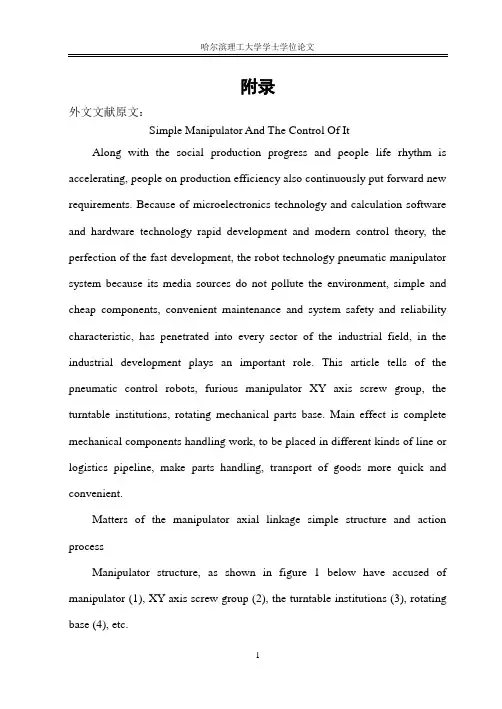
一.四轴联动简易机械手的结构及动作过程机械手结构如下图1所示,有气控机械手(1)、XY轴丝杠组(2)、转盘机构(3)、旋转基座(4)等组成。
图1.机械手结构其运动控制方式为:(1)由伺服电机驱动可旋转角度为360°的气控机械手(有光电传感器确定起始0点);(2)由步进电机驱动丝杠组件使机械手沿X、Y轴移动(有x、y轴限位开关);(3)可回旋360°的转盘机构能带动机械手及丝杠组自由旋转(其电气拖动部分由直流电动机、光电编码器、接近开关等组成);(4)旋转基座主要支撑以上3部分;(5)气控机械手的张合由气压控制(充气时机械手抓紧,放气时机械手松开)。
多自由度机械手毕业论文中英文资料外文翻译文献
毕业论文中英文资料外文翻译文献专业机械设计制造及其自动化课题多自由度机械手机械设计英文原文Automated Tracking and Grasping of a Moving Object with a RoboticHand-Eye SystemAbstractMost robotic grasping tasks assume a stationary or fixed object. In this paper, we explore the requirements for tracking and grasping a moving object. The focus of our work is to achieve a high level of interaction between a real-time vision system capable of tracking moving objects in 3-D and a robot arm with gripper that can be used to pick up a moving object. There is an interest in exploring the interplay of hand-eye coordination for dynamic grasping tasks such as grasping of parts on a moving conveyor system, assembly of articulated parts, or for grasping from a mobile robotic system. Coordination between an organism's sensing modalities and motor control system is a hallmark of intelligent behavior, and we are pursuing the goal of building an integrated sensing and actuation system that can operate in dynamic as opposed to static environments.The system we have built addresses three distinct problems in robotic hand-eye coordination for grasping moving objects: fast computation of 3-D motion parameters from vision, predictive control of a moving robotic arm to track a moving object, and interception and grasping. The system is able to operate at approximately human arm movement rates, and experimental results in which a moving model train is tracked is presented, stably grasped, and picked up by the system. The algorithms we have developed that relate sensing to actuation are quite general and applicable to a variety of complex robotic tasks that require visual feedback for arm and hand control.I. INTRODUCTIONThe focus of our work is to achieve a high level of interaction between real-time vision systems capable of tracking moving objects in 3-D and a robot arm equipped with a dexterous hand that can be used to intercept, grasp, and pick up a movingobject. We are interested in exploring the interplay of hand-eye coordination for dynamic grasping tasks such as grasping of parts on a moving conveyor system, assembly of articulated parts, or for grasping from a mobile robotic system. Coordination between an organism's sensing modalities and motor control system is a hallmark of intelligent behavior, and we are pursuing the goal of building an integrated sensing and actuation system that can operate in dynamic as opposed to static environments.There has been much research in robotics over the last few years that address either visual tracking of moving objects or generalized grasping problems. However, there have been few efforts that try to link the two problems. It is quite clear that complex robotic tasks such as automated assembly will need to have integrated systems that use visual feedback to plan, execute, and monitor grasping.The system we have built addresses three distinct problems in robotic hand-eye coordination for grasping moving objects: fast computation of 3-D motion parameters from vision, predictive control of a moving robotic arm to track a moving object, and interception and grasping. The system is able to operate at approximately human arm movement rates, using visual feedback to track, intercept, stably grasp, and pick up a moving object. The algorithms we have developed that relate sensing to actuation are quite general and applicable to a variety of complex robotic tasks that require visual feedback for arm and hand control.Our work also addresses a very fundamental and limiting problem that is inherent in building integrated sensing actuation systems; integration of systems with different sampling and processing rates. Most complex robotic systems are actually amalgams of different processing devices, connected by a variety of methods. For example, our system consists of three separate computation systems: a parallel image processing computer; a host computer that filters, triangulates, and predicts 3-D position from the raw vision data; and a separate arm control system computer that performs inverse kinematic transformations and joint-level servicing. Each of these systems has its own sampling rate, noise characteristics, and processing delays, which need to be integrated to achieve smooth and stable real-time performance. In our case, this involves overcoming visual processing noise and delays with a predictive filter basedupon a probabilistic analysis of the system noise characteristics. In addition, real-time arm control needs to be able to operate at fast servo rates regardless of whether new predictions of object position are available.The system consists of two fixed cameras that can image a scene containing a moving object (Fig. 1). A PUMA-560 with a parallel jaw gripper attached is used to track and pick up the object as it moves (Fig. 2). The system operates as follows:1) The imaging system performs a stereoscopic optic-flow calculation at each pixel in the image. From these optic-flow fields, a motion energy profile is obtained that forms the basis for a triangulation that can recover the 3-D position of a moving object at video rates.2) The 3-D position of the moving object computed by step 1 is initially smoothed to remove sensor noise, and a nonlinear filter is used to recover the correct trajectory parameters which can be used for forward prediction, and the updated position is sent to the trajectory-planner/arm-control system.3) The trajectory planner updates the joint-level servos of the arm via kinematic transform equations. An additional fixed-gain filter is used to provide servo-level control in case of missed or delayed communication from the vision and filtering system.4) Once tracking is stable, the system commands the arm to intercept the moving object and the hand is used to grasp the object stably and pick it up.The following sections of the paper describe each of these subsystems in detail along with experimental results.П. PREVIOUS WORKPrevious efforts in the areas of motion tracking and real-time control are too numerous to exhaustively list here. We instead list some notable efforts that have inspired us to use similar approaches. Burt et al. [9] have focused on high-speed feature detection and hierarchical scaling of images in order to meet the real-time demands of surveillance and other robotic applications. Related work has been reported by. Lee and Wohn [29] and Wiklund and Granlund [43] who uses image differencing methods to track motion. Corke, Paul, and Wohn [13] report afeature-based tracking method that uses special-purpose hardware to drive a servocontroller of an arm-mounted camera. Goldenberg et al. [16] have developed a method that uses temporal filtering with vision hardware similar to our own. Luo, Mullen, and Wessel [30] report a real-time implementation of motion tracking in 1-D based on Horn and Schunk’s method. Vergheseetul. [41] Report real-time short-range visual tracking of objects using a pipelined system similar to our own. Safadi [37] uses a tracking filter similar to our own and a pyramid-based vision system, but few results are reported with this system. Rao and Durrant-Whyte [36] have implemented a Kalman filter-based decentralized tracking system that tracks moving objects with multiple cameras. Miller [31] has integrated a camera and arm for a tracking task where the emphasis is on learning kinematic and control parameters of the system. Weiss et al. [42] also use visual feedback to develop control laws for manipulation. Brown [8] has implemented a gaze control system that links a robotic “head” containing binocular cameras with a servo controller that allows one to maintain a fixed gaze on a moving object. Clark and Ferrier [12] also have implemented a gaze control system for a mobile robot. A variation of the tracking problems is the case of moving cameras. Some of the papers addressing this interesting problem are [9], [15], [44], and [18].The majority of literature on the control problems encountered in motion tracking experiments is concerned with the problem of generating smooth, up-to-date trajectories from noisy and delayed outputs from different vision algorithms.Our previous work [4] coped with that problem in a similar way as in [38], using an cy- p - y filter, which is a form of steady-state Kalman filter. Other approaches can be found in papers by [33], [34], [28], [6]. In the work of Papanikolopoulos et al. [33], [34], visual sensors are used in the feedback loop to perform adaptive robotic visual tracking. Sophisticated control schemes are described which combine a Kalman filter’s estimation and filtering power with an optimal (LQG) controller which computes the robot’s motion. The vision system uses an optic-flow computation based on the SSD (sum of squared differences) method which, while time consuming, appears to be accurate enough for the tracking task. Efficient use of windows in the image can improve the performance of this method. The authors have presented good tracking results, as well as stated that the controller is robust enough so the use ofmore complex (time-varying LQG) methods is not justified. Experimental results with the CMU Direct Drive Arm П show that the methods are quite accurate, robust, and promising.The work of Lee and Kay [28] addresses the problem of uncertainty of cameras in the robot’s coordinate frame. The fact that cameras have to be strictly fixed in robot’s frame might be quite annoying since each time they are (most often incidentally) displaced; one has to undertake a tedious job of their recalibration. Again, the estimation of the moving object’s position and orientation is done in the Cartesian space and a simple error model is assumed. Andersen et al. [6] adopt a 3rd-order Kalman filter in order to allow a robotic system (consisting of two degrees of freedom) to play the labyrinth game. A somewhat different approach has been explored in the work of Houshangi [24] and Koivo et al. [27]. In these works, the autoregressive (AR) and auto grassier moving-average with exogenous input (ARMAX) models are investigated for visual tracking.Ш. VISION SYSTEMIn a visual tracking problem, motion in the imaging system has to be translated into 3-D scene motion. Our approach is to initially compute local optic-flow fields that measure image velocity at each pixel in the image. A variety of techniques for computing optic-flow fields have been used with varying results includingmatching-based techniques [5], [ 10], [39], gradient-based techniques [23], [32], [ 113, and patio-temporal, energy methods [20], [2]. Optic-flow was chosen as the primitive upon which to base the tracking algorithm for the following reasons.·The ability to track an object in three dimensions implies that there will be motion across the retinas (image planes) that are imaging the scene. By identifying this motion in each camera, we can begin to find the actual 3-D motion.·The principal constraint in the imaging process is high computational speed to satisfy the update process for the robotic arm parameters. Hence, we needed to be able to compute image motion quickly and robustly. The Hom-Schunck optic-flow algorithm (described below) is well suited for real-time computation on our PIPE image processing engine.·We have developed a new framework for computing optic-flow robustly using anestimation-theoretic framework [40]. While this work does not specifically use these ideas, we have future plans to try to adapt this algorithm to such a framework.Our method begins with an implementation of the Horn-Schunck method of computing optic-flow [22]. The underlying assumption of this method is theoptic-flow constraint equation, which assumes image irradiance at time t and t+σt will be the same:If we expand this constraint via a Taylor series expansion, and drop second- and higher-order terms, we obtain the form of the constraint we need to compute normal velocity:Where u and U are the velocities in image space, and Ix, Iy,and It are the spatial and temporal derivatives in the image. This constraint limits the velocity field in an image to lie on a straight line in velocity space. The actual velocity cannot be determined directly from this constraint due to the aperture problem, but one can recover the component of velocity normal to this constraint lineA second, iterative process is usually employed to propagate velocities in image neighborhoods, based upon a variety of smoothness and heuristic constraints. These added neighborhood constraints allow for recovery of the actual velocities u,v in the image. While computationally appealing, this method of determining optic-flow has some inherent problems. First, the computation is done on a pixel-by-pixel basis, creating a large computational demand. Second, the information on optic flow is only available in areas where the gradients defined above exist.We have overcome the first of these problems by using the PIPE image processor [26], [7]. The PIPE is a pipelined parallel image processing computer capable of processing 256 x 256 x 8 bit images at frame rate speeds, and it supports the operations necessary for optic-flow computation in a pixel parallel method (a typical image operation such as convolution, warping, addition subtraction of images can be done in one cycle-l/60 s).The second problem is alleviated by our not needing to know the actual velocities in the image. What we need is the ability to locate and quantify gross image motion robustly. This rules out simple differencing methodswhich are too prone to noise and will make location of image movement difficult. Hence, a set of normal velocities at strong gradients is adequate for our task, precluding the need to iteratively propagate velocities in the image.A. Computing Normal Optic-Flow in Real-TimeOur goal is to track a single moving object in real time. We are using two fixed cameras that image the scene and need to report motion in 3-D to a robotic arm control program. Each camera is calibrated with the 3-D scene, but there is no explicit need to use registered (i.e., scan-line coherence) cameras. Our method computes the normal component of optic-flow for each pixel in each camera image, finds a centurion of motion energy for each image, and then uses triangulation to intersect the back-projected centurions of image motion in each camera. Four processors are used in parallel on the PIPE. The processors are assigned as four per camera-two each for the calculation of X and Y motion energy centurions in each image. We also use a special processor board (ISMAP) to perform real-time histogram. The steps below correspond to the numbers in Fig. 3.1) The camera images the scene and the image is sent to processing stages in the PIPE.2) The image is smoothed by convolution with a Gaussian mask. The convolution operator is a built-in operation in the PIPE and it can be performed in one frame cycle. 3-4) In the next two cycles, two more images are read in, smoothed and buffered, yielding smoothed images Io and I1 and I2.The ability to buffer and pipeline images allows temporal operations on images, albeit at the cost of processing delays (lags) on output. There are now three smoothed images in the PIPE, with the oldest image lagging by 3/60 s.5) Images Io and I2, are subtracted yielding the temporal derivative It.6) In parallel with step 5, image I1is convolved with a 3 x 3 horizontal spatial gradient operator, returning the discrete form of I,. In parallel, the vertical spatial gradient is calculated yielding I, (not shown).7-8)The results from steps 5 and 6 are held in buffers and then are input to alook-up table that divides the temporal gradient at each pixel by the absolute value of the summed horizontal and vertical spatial gradients [which approximates thedenominator in (3)]. This yields the normal velocity in the image at each pixel. These velocities are then threshold and any isolated (i.e., single pixel motion energy) blobs are morphologically eroded. The above threshold velocities are then encoded as gray value 255. In our experiments, we threshold all velocities below 10 pixels per 60 ms to zero velocity.9-10) In order to get the centurion of the motion information, we need the X and Y coordinates of the motion energy. For simplicity, we show only the situation for the X coordinate. The gray-value ramp in Fig. 3 is an image that encodes the horizontal coordinate value (0-255) for each point in the image as a gray value.Thus, it is an image that is black (0) at horizontal pixel 0 and white (255) at horizontal pixel 255. If we logically and each pixel of the above threshold velocity image with the ramp image, we have an image which encodes high velocity pixels with their positional coordinates in the image, and leaves pixels with no motion at zero.11) By taking this result and histogram it, via a special stage of the PIPE which performs histograms at frame rate speeds, we can find the centurion of the moving object by finding the mean of the resulting histogram. Histogram the high-velocity position encoded images yields 256 16-bit values (a result for each intensity in the image). These 256 values can be read off the PIPE via a parallel interface in about 10 ms. This operation is performed in parallel to find the moving object’s Y censored (and in parallel for X and Y centurions for camera 2). The total associated delay time for finding the censored of a moving object becomes 15 cycles or 0.25 s.The same algorithm is run in parallel on the PIPE for the second camera. Once the motion centurions are known for each camera, they are back-projected into the scene using the camera calibration matrices and triangulated to find the actual 3-D location of the movement. Because of the pipelined nature of the PIPE, a new X or Y coordinate is produced every 1/60 s with this delay. While we are able to derive 3-D position from motion stereo at real-time rates, there are a number of sources of noise and error inherent in the vision system. These include stereo triangulation error, moving shadow s which are interpreted as object motion (we use no special lighting in the scene), and small shifts in censored alignments due to the different viewing angles of the cameras, which have a large baseline. The net effect of this is to create a 3-Dposition signal that is accurate enough for gross-level object tracking, but is not sufficient for the smooth and highly accurate tracking required for grasping the object.英文翻译自动跟踪和捕捉系统中的机械手系统摘要——许多机器人抓捕任务都被假设在了一个固定的物体上进行。
机械手设计英文参考文献原文翻译

翻译人:王墨墨山东科技大学文献题目:Automated Calibration of Robot Coordinatesfor Reconfigurable Assembly Systems翻译正文如下:针对可重构装配系统的机器人协调性的自动校准T.艾利,Y.米达,H.菊地,M.雪松日本东京大学,机械研究院,精密工程部摘要为了实现流水工作线更高的可重构性,以必要设备如机器人的快速插入插出为研究目的。
当一种新的设备被装配到流水工作线时,应使其具备校准系统。
该研究使用两台电荷耦合摄像机,基于直接线性变换法,致力于研究一种相对位置/相对方位的自动化校准系统。
摄像机被随机放置,然后对每一个机械手执行一组动作。
通过摄像机检测机械手动作,就能捕捉到两台机器人的相对位置。
最佳的结果精度为均方根值0.16毫米。
关键词:装配,校准,机器人1 介绍21世纪新的制造系统需要具备新的生产能力,如可重用性,可拓展性,敏捷性以及可重构性[1]。
系统配置的低成本转变,能够使系统应对可预见的以及不可预见的市场波动。
关于组装系统,许多研究者提出了分散的方法来实现可重构性[2][3]。
他们中的大多数都是基于主体的系统,主体逐一协同以建立一种新的配置。
然而,协同只是目的的一部分。
在现实生产系统中,例如工作空间这类物理问题应当被有效解决。
为了实现更高的可重构性,一些研究人员不顾昂贵的造价,开发出了特殊的均匀单元[4][5][6]。
作者为装配单元提出了一种自律分散型机器人系统,包含多样化的传统设备[7][8]。
该系统可以从一个系统添加/删除装配设备,亦或是添加/删除装配设备到另一个系统;它通过协同作用,合理地解决了工作空间的冲突问题。
我们可以把该功能称为“插入与生产”。
在重构过程中,校准的装配机器人是非常重要的。
这是因为,需要用它们来测量相关主体的特征,以便在物理主体之间建立良好的协作关系。
这一调整必须要达到表1中所列到的多种标准要求。
可迅速布置的机械手系统外文翻译、外文文献翻译、中英文翻译
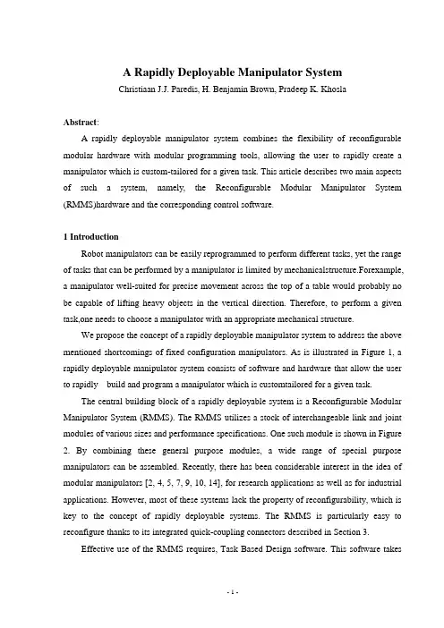
A Rapidly Deployable Manipulator SystemChristiaan J.J. Paredis, H. Benjamin Brown, Pradeep K. KhoslaAbstract:A rapidly deployable manipulator system combines the flexibility of reconfigurable modular hardware with modular programming tools, allowing the user to rapidly create a manipulator which is custom-tailored for a given task. This article describes two main aspects of such a system, namely, the Reconfigurable Modular Manipulator System (RMMS)hardware and the corresponding control software.1 IntroductionRobot manipulators can be easily reprogrammed to perform different tasks, yet the range of tasks that can be performed by a manipulator is limited by mechanicalstructure.Forexample, a manipulator well-suited for precise movement across the top of a table would probably no be capable of lifting heavy objects in the vertical direction. Therefore, to perform a given task,one needs to choose a manipulator with an appropriate mechanical structure.We propose the concept of a rapidly deployable manipulator system to address the above mentioned shortcomings of fixed configuration manipulators. As is illustrated in Figure 1, a rapidly deployable manipulator system consists of software and hardware that allow the user to rapidly build and program a manipulator which is customtailored for a given task.The central building block of a rapidly deployable system is a Reconfigurable Modular Manipulator System (RMMS). The RMMS utilizes a stock of interchangeable link and joint modules of various sizes and performance specifications. One such module is shown in Figure 2. By combining these general purpose modules, a wide range of special purpose manipulators can be assembled. Recently, there has been considerable interest in the idea of modular manipulators [2, 4, 5, 7, 9, 10, 14], for research applications as well as for industrial applications. However, most of these systems lack the property of reconfigurability, which is key to the concept of rapidly deployable systems. The RMMS is particularly easy to reconfigure thanks to its integrated quick-coupling connectors described in Section 3.Effective use of the RMMS requires, Task Based Design software. This software takesas input descriptions of the task and of the available manipulator modules; it generates as output a modular assembly configuration optimally suited to perform the given task. Several different approaches have been used successfully to solve simpli-fied instances of this complicated problem.A third important building block of a rapidly deployable manipulator system is a framework for the generation of control software. To reduce the complexity of softwaregeneration for real-time sensor-based control systems, a software paradigm called software assembly has been proposed in the Advanced Manipulators Laboratory at CMU.This paradigm combines the concept of reusable and reconfigurable software components, as is supported by the Chimera real-time operating system [15], with a graphical user interface and a visual programming language, implemented in OnikaA lthough the software assembly paradigm provides thesoftware infrastructure for rapidly programming manipulator systems, it does not solve the programming problem itself. Explicit programming of sensor-based manipulator systems is cumbersome due to the extensive amount of detail which must be specified for the robot to perform the task. The software synthesis problem for sensor-based robots can be simplified dramatically, by providing robust robotic skills, that is, encapsulated strategies for accomplishing common tasks in the robots task domain [11]. Such robotic skills can then be used at the task level planning stage without having to consider any of the low-level detailsAs an example of the use of a rapidly deployable system,consider a manipulator in a nuclear environment where it must inspect material and space for radioactive contamination, or assemble and repair equipment. In such an environment, widely varied kinematic (e.g., workspace) and dynamic (e.g., speed, payload) performance is required, and these requirements may not be known a priori. Instead of preparing a large set of different manipulators to accomplish these tasks—an expensive solution—one can use a rapidly deployable manipulator system. Consider the following scenario: as soon as a specific task is identified, the task based design software determinesthe task. This optimal configuration is thenassembled from the RMMS modules by a human or, in the future, possibly by another manipulator. The resulting manipulator is rapidly programmed by using the software assembly paradigm and our library of robotic skills. Finally,the manipulator is deployed toperform its task.Although such a scenario is still futuristic, the development of the reconfigurable modular manipulator system, described in this paper, is a major step forward towards our goal of a rapidly deployable manipulator system.Our approach could form the basis for the next generation of autonomous manipulators, in which the traditional notion of sensor-based autonomy is extended to configuration-based autonomy. Indeed, although a deployed system can have all the sensory and planning information it needs, it may still not be able to accomplish its task because the task is beyond the system’s physical capabilities. A rapidly deployable system, on the other hand, could adapt its physical capabilities based on task specifications and, with advanced sensing, control, and planning strategies, accomplish the task autonomously.2 Design of self-contained hardware modulesIn most industrial manipulators, the controller is a separate unit housing the sensor interfaces, power amplifiers, and control processors for all the joints of the manipulator.A large number of wires is necessary to connect this control unit with the sensors, actuators and brakes located in each of the joints of the manipulator. The large number of electrical connections and the non-extensible nature of such a system layout make it infeasible for modular manipulators. The solution we propose is to distribute the control hardware to each individual module of the manipulator. These modules then become self-contained units which include sensors, an actuator, a brake, a transmission, a sensor interface, a motor amplifier, and a communication interface, as is illustrated in Figure 3. As a result, only six wires are requiredfor power distribution and data communication.2.1 Mechanical designThe goal of the RMMS project is to have a wide variety of hardware modules available. So far, we have built four kinds of modules: the manipulator base, a link module, three pivot joint modules (one of which is shown in Figure 2), and one rotate joint module. The base module and the link module have no degrees-of-freedom; the joint modules have one degree-of-freedom each. The mechanical design of the joint modules compactly fits a DC-motor, a fail-safe brake, a tachometer, a harmonic drive and a resolver.The pivot and rotate joint modules use different outside housings to provide theright-angle or in-line configuration respectively, but are identical internally. Figure 4 shows in cross-section the internal structure of a pivot joint. Each joint module includes a DC torque motor and 100:1 harmonic-drive speed reducer, and is rated at a maximum speed of 1.5rad/s and maximum torque of 270Nm. Each module has a mass of approximately 10.7kg. A single, compact, X-type bearing connects the two joint halves and provides the needed overturning rigidity. A hollow motor shaft passes through all the rotary components, and provides achannel for passage of cabling with minimal flexing.2.2 Electronic designThe custom-designed on-board electronics are also designed according to the principle of modularity. Each RMMS module contains a motherboard which provides the basic functionality and onto which daughtercards can be stacked to add module specific functionality.The motherboard consists of a Siemens 80C166 microcontroller, 64K of ROM, 64K of RAM, an SMC COM20020 universal local area network controller with an RS-485 driver, and an RS-232 driver. The function of the motherboard is to establish communication with the host interface via an RS-485 bus and to perform the lowlevel control of the module, as is explained in more detail in Section 4. The RS-232 serial bus driver allows for simple diagnostics and software prototyping.A stacking connector permits the addition of an indefinite number of daughtercards with various functions, such as sensor interfaces, motor controllers, RAM expansion etc. In our current implementation, only modules with actuators include a daughtercard. This card contains a 16 bit resolver to digital converter, a 12 bit A/D converter to interface with the tachometer, and a 12 bit D/A converter to control the motor amplifier; we have used an ofthe-shelf motor amplifier (Galil Motion Control model SSA-8/80) to drive the DC-motor. For modules with more than one degree-of-freedom, for instance a wrist module, more than one such daughtercard can be stacked onto the same motherboard.3 Integrated quick-coupling connectorsTo make a modular manipulator be reconfigurable, it is necessary that the modules canbe easily connected with each other. We have developed a quick-coupling mechanism with which a secure mechanical connection between modules can be achieved by simply turning a ring handtight; no tools are required. As shown in Figure 5, keyed flanges provide precise registration of the two modules. Turning of the locking collar on the male end produces two distinct motions: first the fingers of the locking ring rotate (with the collar) about 22.5 degrees and capture the fingers on the flanges; second, the collar rotates relative to the locking ring, while a cam mechanism forces the fingers inward to securely grip the mating flanges. A ball- transfer mechanism between the collar and locking ring automatically produces this sequence of motions.At the same time the mechanical connection is made,pneumatic and electronic connections are also established. Inside the locking ring is a modular connector that has 30 male electrical pins plus a pneumatic coupler in the middle. These correspond to matching female components on the mating connector. Sets of pins are wired in parallel to carry the 72V-25A power for motors and brakes, and 48V–6A power for the electronics. Additional pins carry signals for two RS-485 serial communication busses and four video busses. A plastic guide collar plus six alignment pins prevent damage to the connector pins and assure proper alignment. The plastic block holding the female pins can rotate in the housing to accommodate the eight different possible connection orientations (8@45 degrees). The relative orientation is automatically registered by means of an infrared LED in the female connector and eight photodetectors in the male connector.4 ARMbus communication systemEach of the modules of the RMMS communicates with a VME-based host interface over a local area network called the ARMbus; each module is a node of the network. The communication is done in a serial fashion over an RS-485 bus which runs through the length of the manipulator. We use the ARCNET protocol [1] implemented on a dedicated IC (SMC COM20020). ARCNET is a deterministic token-passing network scheme which avoids network collisions and guarantees each node its time to access the network. Blocks of information called packets may be sent from any node on the network to any one of the other nodes, or to all nodes simultaneously (broadcast). Each node may send one packet each time itgets the token. The maximum network throughput is 5Mb/s.The first node of the network resides on the host interface card, as is depicted in Figure 6. In addition to a VME address decoder, this card contains essentially the same hardware one can find on a module motherboard. The communication between the VME side of the card and the ARCNET side occurs through dual-port RAM.There are two kinds of data passed over the local area network. During the manipulator initialization phase, the modules connect to the network one by one, starting at the base and ending at the end-effector. On joining the network, each module sends a data-packet to the host interface containing its serial number and its relative orientation with respect to the previous module. This information allows us to automatically determine the current manipulator configuration.During the operation phase, the host interface communicates with each of the nodes at 400Hz. The data that is exchanged depends on the control mode—centralized or distributed. In centralized control mode, the torques for all the joints are computed on the VME-based real-time processing unit (RTPU), assembled into a data-packet by the microcontroller on the host interface card and broadcast over the ARMbus to all the nodes of the network. Each node extracts its torque value from the packet and replies by sending a data-packet containing the resolver and tachometer readings. In distributed control mode, on the other hand, the host computer broadcasts the desired joint values and feed-forward torques. Locally, in each module, the control loop can then be closed at a frequency much higher than 400Hz. The modules still send sensor readings back to the host interface to be used in the computation of the subsequent feed-forward torque.5 Modular and reconfigurable control softwareThe control software for the RMMS has been developed using the Chimera real-time operating system, which supports reconfigurable and reusable software components [15]. The software components used to control the RMMS are listed in Table 1. The trjjline, dls, and grav_comp components require the knowledge of certain configuration dependent parameters of the RMMS, such as the number of degrees-of-freedom, the Denavit-Hartenberg parameters etc. During the initialization phase, the RMMS interface establishes contact with each of thehardware modules to determine automatically which modules are being used and in which order and orientation they have been assembled. For each module, a data file with a parametric model is read. By combining this information for all the modules, kinematic and dynamic models of the entire manipulator are built.After the initialization, the rmms software component operates in a distributed control mode in which the microcontrollers of each of the RMMS modules perform PID control locally at 1900Hz. The communication between the modules and the host interface is at 400Hz, which can differ from the cycle frequency of the rmms software component. Since we use a triple buffer mechanism [16] for the communication through the dual-port RAM on the ARMbus host interface, no synchronization or handshaking is necessary.Because closed form inverse kinematics do not exist for all possible RMMS configurations, we use a damped least-squares kinematic controller to do the inverse kinematics computation numerically..6 Seamless integration of simulationTo assist the user in evaluating whether an RMMS con- figuration can successfully complete a given task, we have built a simulator. The simulator is based on the TeleGrip robot simulation software from Deneb Inc., and runs on an SGI Crimson which is connected with the real-time processing unit through a Bit3 VME-to-VME adaptor, as is shown in Figure 6.A graphical user interface allows the user to assemble simulated RMMS configurations very much like assembling the real hardware. Completed configurations can be tested and programmed using the TeleGrip functions for robot devices. The configurations can also be interfaced with the Chimera real-time softwarerunning on the same RTPUs used to control the actual hardware. As a result, it is possible to evaluate not only the movements of the manipulator but also the realtime CPU usage and load balancing. Figure 7 shows an RMMS simulation compared with the actual task execution.7 SummaryWe have developed a Reconfigurable Modular Manipulator System which currently consists of six hardware modules, with a total of four degrees-of-freedom. These modules canbe assembled in a large number of different configurations to tailor the kinematic and dynamic properties of the manipulator to the task at hand. The control software for the RMMS automatically adapts to the assembly configuration by building kinematic and dynamic models of the manipulator; this is totally transparent to the user. To assist the user in evaluating whether a manipulator configuration is well suited for a given task, we have also built a simulator.AcknowledgmentThis research was funded in part by DOE under grant DE-F902-89ER14042, by Sandia National Laboratories under contract AL-3020, by the Department of Electrical and Computer Engineering, and by The Robotics Institute, Carnegie Mellon University.The authors would also like to thank Randy Casciola, Mark DeLouis, Eric Hoffman, and Jim Moody for their valuable contributions to the design of the RMMS system.可迅速布置的机械手系统作者:Christiaan J.J. Paredis, H. Benjamin Brown, Pradeep K. Khosla摘要:一个迅速可部署的机械手系统,可以使再组合的标准化的硬件的灵活性用标准化的编程工具结合,允许用户迅速建立为一项规定的任务来通常地控制机械手。
机械手外文翻译
机械手外文翻译外文文献原文:Along with the social production progress and people life rhythm is accelerating, people on production efficiency also continuously put forward new requirements. Because of microelectronics technology and calculation software and hardware technology rapid development and modern control theory, theperfection of the fast development, the robot technology pneumatic manipulator system because its media sources do not pollute the environment, simple and cheap components, convenient maintenance and system safety and reliabilitycharacteristic, has penetrated into every sector of the industrial field, in the industrial development plays an important role. This article tells of the pneumatic control robots, furious manipulator XY axis screw group, the turntable institutions,rotating mechanical parts base. Main effect is complete mechanical components handling work, to be placed in different kinds of line or logistics pipeline, make parts handling, transport of goods more quick and convenient.Matters of the manipulator axial linkage simple structure and action processManipulator structure, as shown in figure 1 below have accused of manipulator (1), XY axis screw group (2), the turntable institutions (3), rotating base (4), etc.Its motion control mode is: (1) can rotate by servomotor Angle for 360 ? breath control manipulator (photoelectric sensor sure start 0 point); (2) by stepping motor drive screw component make along the X, Y manipulators move (have X, Y axis limit switches); (3) can rotates 360 ? can drive the turntable institutionsmanipulators and bushings free rotation (its electric drag in partby the dc motivation, photoelectric encoder, close to switch etc); (4) rotating base main support above 3 parts; (5) gas control manipulator by pressure control (Zhangclose when pressed on, put inflatable robot manipulators loosen)when gas.Its working process for: when the goods arrived, manipulator system begins to move; Stepping motor control, while the other start downward motion along thehorizontal axis of the step-motor controller began to move exercise; Servo motordriver arrived just grab goods manipulators rotating the orientation of the place, then inflatable, manipulator clamped goods.Vertical axis stepper motor drive up, the other horizontal axis stepper motordriver started to move forward; rotary DC motor rotation so that the whole robot motion, go to the cargo receiving area; longitudinal axis stepper motor driven down again, arrived at the designated location, Bleed valve, mechanical hand releasethe goods; system back to the place ready for the next action.II. Control device selectionTo achieve precise control purposes, according to market conditions, selection of a variety of key components as follows:1. Stepper motor and driveMechanical hand vertical axis (Y axis) and horizontal (X axis) is chosen Motor Technology Co., Ltd. Beijing Stone 42BYG250C type of two-phase hybrid steppingmotor, step angle of 0.9 ? / 1.8 ?, current is 1.5A. M1 is the horizontal axis motor driven manipulator stretch, shrink; M2 is thevertical axis motor driven manipulator rise and fall. The choice of stepper motor drive is SH-20403 type, the drive uses10 ~ 40V DC power supply, H-phase bridge bipolar constant current drive, themaximum output current of 3A of the 8 optional, maximum fine of 64 segments of7 sub-mode optional optical isolation, standard single-pulse interface, with offlinecapabilities to maintain semi-sealed enclosure can be adapted to environmentalconditions even worse, provide semi-current energy-saving mode automatically.Drive the internal switching power supply design to ensure that the drive can be adapted to a wide voltage range, the user can according to their circumstances to choose between the 10 ~ 40VDC. Generally the higher rated power supply voltagecan improve high-speed torque motor, but the drive will increase the loss and temperature rise. The maximum output drive current is 3A / phase (peak), six drive-panel DIP switch on the first three can be combined 5,6,7 8 out of state,corresponding to the 8 kinds of output current from 0.9A to 3A to meet the different motors. The drive can provide full step, half step improvement, subdivision 4,8 segments, 16 segments, 32 segments and 64 segments of 7 operating modes.The use of six of the drive panel DIP switches 1,2and3 can be combined fromthree different states.2. Servo motors and drivesManipulator with Panasonic servo motor rotational movement A series of small inertia MSMA5AZA1G, the rated 50W, 100/200V share, rotary incrementalencoder specifications (number of pulses 2500p / r, resolution of 10000p / r, Lead 11 lines) ; a seal, no brakes, shaft with keyway connections. The motor uses Panasonic's unique algorithms, the rate increased by 2 times the frequencyresponse, to 500Hz; positioning over the past adjust the scheduled time by Panasonic servo motor products for the V Series of 1 / 4. With the resonance suppression, control, closed loop control, can make up for lack of mechanical rigidity, in order to achieve high positioning accuracy can also be an external grating to form closed loop control to further improve accuracy. With a conventional automatic gain adjustment and real-time automatic gainInterest adjustment in the automatic gain adjustment methods, which also hasRS-485, RS-232C communication port, the host controller can control up to 16 axes. Servo motor drives are a series MSDA5A3A1A, applicable to small inertiamotor.3. DC machine360 ? swing of the turntable can be a brushless DC motor driven organization, thesystem is chosen when the profit company in Beijing and the57BL1010H1 brushless DC motor, its speed range, low-speed torque, smooth running, lownoise, high efficiency. Brushless DC motor drive using the Beijing and when Lee'sBL-0408 produced by the drive, which uses 24 ~ 48V DC power supply, a start-stop and steering control, over current, overvoltage and lockedrotor protection,and there is failure alarm output external analog speed control, braking down so fast.4. Rotary encoderCan swing 360 ? in the body on the turntable, fitted with OMRON E6A2 produced incremental rotary encoder, the encoder signals to the PLC, to achieveprecise positioning of rotary bodies.5. PLC SelectionAccording to the system design requirements, the choice of OMRON CPM2Aproduced minicomputer. CPM2A in a compact unit integrated with a variety of properties, including the synchronization pulse control, interrupt input, pulse output, analog set and clock functions. CPM2A the CPU unit is a stand-alone unit,capable of handling a wide range of application of mechanical control, it is built in the device control unit for the ideal product. Ensure the integrity of communications and personal computers, other OMRON PC and OMRON Programmable Terminal communication. The communication capability allows the robot to Axis simple easyintegration into industrial control systems.III. Software programming1. Software flow chartPLC programming flow chart is based. Only the design flow, it may be smoothand easy to prepare and write a statement form the ladder, and ultimately complete the process design. So write a flow chart of program design is critical to the task first thing to do. Axis Manipulator based on simple control requirements, drawing flow chart shown in Figure 2.2. Program partBecause space is limited, here only paper listed the first two programsegment for readers see.IV. ConclusionAxis simple robot state by the various movements and PLC control,the robot can not only meet the manual, semi-automatic mode of operation required for sucha large number of buttons, switches, position detection point requirements, but also through the interface components and Computer Organization PLC industrial LAN, network communication and network control. Axis simple robot can be easilyembedded into industrial production pipeline.中文译文:随着社会生产不断进步和人们生活节奏不断加快,人们对生产效率也不断提出新要求。
简易机械手及控制外文文献翻译、机械手类中英翻译、外文翻译
附录外文文献原文:Simple Manipulator And The Control Of ItAlong with the social production progress and people life rhythm is accelerating, people on production efficiency also continuously put forward new requirements. Because of microelectronics technology and calculation software and hardware technology rapid development and modern control theory, the perfection of the fast development, the robot technology pneumatic manipulator system because its media sources do not pollute the environment, simple and cheap components, convenient maintenance and system safety and reliability characteristic, has penetrated into every sector of the industrial field, in the industrial development plays an important role. This article tells of the pneumatic control robots, furious manipulator XY axis screw group, the turntable institutions, rotating mechanical parts base. Main effect is complete mechanical components handling work, to be placed in different kinds of line or logistics pipeline, make parts handling, transport of goods more quick and convenient.Matters of the manipulator axial linkage simple structure and action processManipulator structure, as shown in figure 1 below have accused of manipulator (1), XY axis screw group (2), the turntable institutions (3), rotating base (4), etc.Figure 1 Manipulator StructureIts motion control mode is: (1) can rotate by servomotor Angle for 360 °breath control manipulator (photoelectric sensor sure start 0 point); (2) by stepping motor drive screw component make along the X, Y manipulators move (have X, Y axis limit switches); (3) can rotates 360 °can drive the turntable institutions manipulators and bushings free rotation (its electric drag in part by the dc motivation, photoelectric encoder, close to switch etc); (4) rotating base main support above 3 parts; (5) gas control manipulator by pressure control (Zhang close when pressed on, put inflatable robot manipulators loosen) when gas.Its working process for: when the goods arrived, manipulator system begins to move; Stepping motor control, while the other start downward motion along the horizontal axis of the step-motor controller began to move exercise; Servo motor driver arrived just grab goods manipulators rotating the orientation of the place, then inflatable, manipulator clamped goods.Vertical axis stepper motor drive up, the other horizontal axis stepper motor driver started to move forward; rotary DC motor rotation so that the whole robot motion, go to the cargo receiving area; longitudinal axis stepper motor driven down again, arrived at the designated location, Bleed valve, mechanical hand release the goods; system back to the place ready for the next action.II.Device controlTo achieve precise control purposes, according to market conditions, selection of a variety of keycomponents as follows:1. Stepper motor and driveMechanical hand vertical axis (Y axis) and horizontal (X axis) is chosen Motor Technology Co., Ltd. Beijing Stone 42BYG250C type of two-phase hybrid stepping motor, step angle of 0.9 °/ 1.8 °, current is 1.5A. M1 is the horizontal axis motor driven manipulator stretch, shrink; M2 is the vertical axis motor driven manipulator rise and fall. The choice of stepper motor drive is SH-20403 type, the drive uses 10 ~ 40V DC power supply, H-phase bridge bipolar constant current drive, the maximum output current of 3A of the 8 optional, maximum fine of 64 segments of 7 sub-mode optional optical isolation, standard single-pulse interface, with offline capabilities to maintain semi-sealed enclosure can be adapted to environmental conditions even worse, provide semi-current energy-saving mode automatically. Drive the internal switching power supply design to ensure that the drive can be adapted to a wide voltagerange, the user can according to their circumstances to choose between the 10 ~ 40VDC. Generally the higher rated power supply voltage can improve high-speed torque motor, but the drive will increase the loss and temperature rise. The maximum output drive current is 3A / phase (peak), six drive-panel DIP switch on the first three can be combined 5,6,7 8 out of state, corresponding to the 8 kinds of output current from 0.9A to 3A to meet the different motors. The drive can provide full step, half step improvement, subdivision 4, 8 segments, 16 segments, 32 segments and 64 segments of 7 operating modes. The use of six of the drive panel DIP switches 1,2and3 can be combined from three different states.2. Servo motors and drivesManipulator with Panasonic servo motor rotational movement A series of small inertia MSMA5AZA1G, the rated 50W, 100/200V share, rotary incremental encoder specifications (number of pulses 2500p / r, resolution of 10000p / r, Lead 11 lines) ; a seal, no brakes, shaft with keyway connections. The motor uses Panasonic's unique algorithms, the rate increased by 2 times the frequency response, to 500Hz; positioning over the past adjust the scheduled time by Panasonic servo motor products for the V Series of 1 / 4. With the resonance suppression, control, closed loop control, can make up for lack of mechanical rigidity, in order to achieve high positioning accuracy can also be an external grating to form closed loop control to further improve accuracy. With a conventional automatic gain adjustment and real-time automatic gainInterest adjustment in the automatic gain adjustment methods, which also has RS-485, RS-232C communication port, the host controller can control up to 16 axes. Servo motor drives are a series MSDA5A3A1A, applicable to small inertia motor.3. DC machine360 ° swing of the turntable can be a brushless DC motor driven organization, the system is chosen when the profit company in Beijing and the 57BL1010H1 brushless DC motor, its speed range, low-speed torque, smooth running, low noise, high efficiency. Brushless DC motor drive using the Beijing and when Lee's BL-0408 produced by the drive, which uses 24 ~ 48V DC power supply, a start-stop and steering control, over current, overvoltage and locked rotor protection, and there is failure alarm output external analog speed control, braking down so fast.4. Rotary encoderCan swing 360 ° in the body on the turntable, fitted with OMRON E6A2 produced incremental rotary encoder, the encoder signals to the PLC, to achieve precise positioning of rotary bodies.5. PLC SelectionAccording to the system design requirements, the choice of OMRON CPM2A produced minicomputer. CPM2A in a compact unit integrated with a variety of properties, including the synchronization pulse control, interrupt input, pulse output, analog set and clock functions. CPM2A the CPU unit is astand-alone unit, capable of handling a wide range of application of mechanical control, it is built in the device control unit for the ideal product. Ensure the integrity of communications and personal computers, other OMRON PC and OMRON Programmable Terminal communication. The communication capability allows the robot to Axis simple easy integration into industrial control systems.III. Software programming1. Software flow chartPLC programming flow chart is based. Only the design flow, it may be smooth and easy to prepare and write a statement form the ladder, and ultimately complete the process design. So write a flow chart of program design is critical to the task first thing to do. Axis Manipulator based on simple control requirements, drawing flow chart shown in Figure 2.Figure 2 Software flow chart2. Program partBecause space is limited, here only paper listed the first two program segment for readers see.Figure 3 Program partIV. ConclusionAxis simple robot state by the various movements and PLC control, the robot can not only meet the manual, semi-automatic mode of operation required for such a large number of buttons, switches, position detection point requirements, but also through the interface components and Computer Organization PLC industrial LAN, network communication and network control. Axis simple robot can be easily embedded into industrial production pipeline.中文译文:简易机械手及控制随着社会生产不断进步和人们生活节奏不断加快,人们对生产效率也不断提出新要求。
关于现代工业机械手外文文献翻译@中英文翻译@外文翻译
附录About Modenr Industrial Manipulayor Robot is a type of mechantronics equipment which synthesizes the last research achievement of engine and precision engine, micro-electronics and computer, automation control and drive, sensor and message dispose and artificial intelligence and so on. With the development of economic and the demand for automation control, robot technology is developed quickly and all types of the robots products are come into being. The practicality use of robot not only solves the problems which are difficult to operate for human being, but also advances the industrial automation program. Modern industrial robots are true marvels of engineering. A robot the size of a person can easily carry a load over one hundred pounds and move it very quickly with a repeatability of 0.006inches. Furthermore these robots can do that 24hours a day for years on end with no failures whatsoever. Though they are reprogrammable, in many applications they are programmed once and then repeat that exact same task for years.At present, the research and development of robot involves several kinds of technology and the robot system configuration is so complex that the cost at large is high which to a certain extent limit the robot abroad use. To development economic practicality and high reliability robot system will be value to robot social application and economy development. With he rapidprogress with the control economy and expanding of the modern cities, the let of sewage is increasing quickly; with the development of modern technology and the enhancement of consciousness about environment reserve, more and more people realized the importance and urgent of sewage disposal. Active bacteria method is an effective technique for sewage disposal. The abundance requirement for lacunaris plastic makes it is a consequent for plastic producing with automation and high productivity. Therefore, it is very necessary to design a manipulator that can automatically fulfill the plastic holding. With the analysis of the problems in the design of the plastic holding manipulator and synthesizing the robot research and development condition in recent years, a economic scheme is concluded on the basis of the analysis of mechanical configuration, transform system, drive device and control system and guided by the idea of the characteristic and complex of mechanical configuration, electronic, software and hardware. In this article, the mechanical configuration combines the character of direction coordinate which can improve the stability and operation flexibility of the system. The main function of the transmission mechanism is to transmit power to implement department and complete the necessary movement. In this transmission structure, the screw transmission mechanism transmits the rotary motion into linear motion. Worm gear can give vary transmission ratio. Both of the transmission mechanisms have a characteristic of compact structure. The design of drive system often is limited by the environment condition and the factor of costand technical lever. The step motor can receive digital signal directly and has the ability to response outer environment immediately and has no accumulation error, which often is used in driving system. In this driving system, open-loop control system is composed of stepping motor, which can satisfy the demand not only for control precision but also for the target of economic and practicality. On this basis, the analysis of stepping motor in power calculating and style selecting is also given. The analysis of kinematics and dynamics for object holding manipulator is given in completing the design of mechanical structure and drive system.Current industrial approaches to robot arm control treat each joint of the robot arm as a simple joint servomechanism. The servomechanism approach models the varying dynamics of a manipulator inadequately because it neglects the motion and configuration of the whole arm mechanism. These changes in the parameters of the controlled system sometimes are significant enough to render conventional feedback control strategies ineffective. The result is reduced servo response speed and damping, limiting the precision and speed of the end-effecter and making it appropriate only for limited-precision tasks. Manipulators controlled in this manner move at slow speeds with unnecessary vibrations. Any significant performance gain in this and other areas of robot arm control require the consideration of more efficient dynamic models, sophisticated control approaches, and the use of dedicated computer architectures and parallel processing techniques.In the industrial production and other fields, people often endangered by such factors as high temperature, corrode, poisonous gas and so forth at work, which have increased labor intensity and even jeopardized the life sometimes. The corresponding problems are solved since the robot arm comes out. The arms can catch, put and carry objects, and its movements are flexible and diversified. It applies to medium and small-scale automated production in which production varieties can be switched. And it is widely used on soft automatic line. The robot arms are generally made by withstand high temperatures, resist corrosion of materials to adapt to the harsh environment. So they reduced the labor intensity of the workers significantly and raised work efficiency. The robot arm is an important component of industrial robot, and it can be called industrial robots on many occasions. Industrial robot is set machinery, electronics, control, computers, sensors, artificial intelligence and other advanced technologies in the integration of multidisciplinary important modern manufacturing equipment. Widely using industrial robots, not only can improve product quality and production, but also is of great significance for physical security protection, improvement of the environment for labor, reducing labor intensity, improvement of labor productivity, raw material consumption savings and lowering production costs.There are such mechanical components as ball footbridge, slides, air control mechanical hand and so on in the design. A programmable controller, a programming device, stepping motors, stepping motors drives, direct currentmotors, sensors, switch power supply, an electromagnetism valve and control desk are used in electrical connection.Robot is the automated production of a kind used in the pr ocess of crawling and moving piece features automatic device, wh ich is mechanized and automated production process developed a n ew type of device. In recent years, as electronic technology, e specially computer extensive use of robot development and product ion of hightech fields has become a rapidly developed a new te chnology, which further promoted the development of robot, allowi ng robot to better achieved with the combination of mechanizatio n and automation. Robot can replace humans completed the risk o f duplication of boring work, to reduce human labor intensity a nd improve labor productivity. Manipulator has been applied more and more widely, in the machinery industry, it can be used f or parts assembly, work piece handling, loading and unloading, p articularly in the automation of CNC machine tools, modular mach ine tools more commonly used. At present, the robot has develop ed into a FMS flexible manufacturing systems and flexible manufa cturing cell in an important component of the FMC. The machine tool equipment and machinery in hand together constitute a fle xible manufacturing system or a flexible manufacturing cell, it was adapted to small and medium volume production, you can savea huge amount of the work piece conveyor device, compact, and adaptable. When the work piece changes, flexible production sys tem is very easy to change will help enterprises to continuousl y update the marketable variety, improve product quality, and be tter adapt to market competition. At present, China's industrial robot technology and its engineering application level and comp arable to foreign countries there is a certain distance, applica tion and industrialization of the size of the low level of rob ot research and development of a direct impact on raising the level of automation in China, from the economy, technical consid erations are very necessary. Therefore, the study of mechanical hand design is very meaningful.关于现代工业机械手机器人是典型的机电一体化装置,它综合运用了机械与精密机械、微电子与计算机、自动控制与驱动、传感器与信息处理以及人工智能等多学科的最新研究成果,随着经济技术的发展和各行各业对自动化程度要求的提高,机器人技术得到了迅速发展,出现了各种各样的机器人产品。
机械毕业设计英文外文翻译简易机械手及控制
附录外文文献原文:Simple Manipulator And The Control Of ItAlong with the social production progress and people life rhythm is accelerating, people on production efficiency also continuously put forward new requirements. Because of microelectronics technology and calculation software and hardware technology rapid development and modern control theory, the perfection of the fast development, the robot technology pneumatic manipulator system because its media sources do not pollute the environment, simple and cheap components, convenient maintenance and system safety and reliability characteristic, has penetrated into every sector of the industrial field, in the industrial development plays an important role. This article tells of the pneumatic control robots, furious manipulator XY axis screw group, the turntable institutions, rotating mechanical parts base. Main effect is complete mechanical components handling work, to be placed in different kinds of line or logistics pipeline, make parts handling, transport of goods more quick and convenient.Matters of the manipulator axial linkage simple structure and action processManipulator structure, as shown in figure 1 below have accused of manipulator (1), XY axis screw group (2), the turntable institutions (3), rotating base (4), etc.Figure 1 Manipulator StructureIts motion control mode is: (1) can rotate by servomotor Angle for 360 °breath control manipulator (photoelectric sensor sure start 0 point); (2) by stepping motor drive screw component make along the X, Y manipulators move (have X, Y axis limit switches); (3) can rotates 360 °can drive the turntable institutions manipulators and bushings free rotation (its electric drag in part by the dc motivation, photoelectric encoder, close to switch etc); (4) rotating base main support above 3 parts; (5) gas control manipulator by pressure control (Zhang close when pressed on, put inflatable robot manipulators loosen) when gas.Its working process for: when the goods arrived, manipulator system begins to move; Stepping motor control, while the other start downward motion along the horizontal axis of the step-motor controller began to move exercise; Servo motor driver arrived just grab goods manipulators rotating the orientation of the place, then inflatable, manipulator clamped goods.Vertical axis stepper motor drive up, the other horizontal axis stepper motor driver started to move forward; rotary DC motor rotation so that the whole robot motion, go to the cargo receiving area; longitudinal axis stepper motor driven down again, arrived at the designated location, Bleed valve,mechanical hand release the goods; system back to the place ready for the next action.II.Device controlTo achieve precise control purposes, according to market conditions, selection of a variety of keycomponents as follows:1. Stepper motor and driveMechanical hand vertical axis (Y axis) and horizontal (X axis) is chosen Motor Technology Co., Ltd. Beijing Stone 42BYG250C type of two-phase hybrid stepping motor, step angle of 0.9 ° / 1.8 °, current is 1.5A. M1 is the horizontal axis motor driven manipulator stretch, shrink; M2 is the vertical axis motor driven manipulator rise and fall. The choice of stepper motor drive is SH-20403 type, the drive uses 10 ~ 40V DC power supply, H-phase bridge bipolar constant current drive, the maximum output current of 3A of the 8 optional, maximum fine of 64 segments of 7 sub-mode optional optical isolation, standard single-pulse interface, with offline capabilities to maintain semi-sealed enclosure can be adapted to environmental conditions even worse, provide semi-current energy-saving mode automatically. Drive the internal switching power supply design to ensure that the drive can be adapted to a wide voltage range, the user can according to their circumstances to choose between the 10 ~ 40VDC. Generally the higher rated power supply voltage can improve high-speed torque motor, but the drive will increase the loss and temperature rise. The maximum output drive current is 3A / phase (peak), six drive-panel DIP switch on the first three can be combined 5,6,7 8 out of state, corresponding to the 8 kinds of output current from 0.9A to 3A to meet the different motors. The drive can provide full step, half step improvement, subdivision 4, 8 segments, 16 segments, 32 segments and 64segments of 7 operating modes. The use of six of the drive panel DIP switches 1,2and3 can be combined from three different states.2. Servo motors and drivesManipulator with Panasonic servo motor rotational movement A series of small inertia MSMA5AZA1G, the rated 50W, 100/200V share, rotary incremental encoder specifications (number of pulses 2500p / r, resolution of 10000p / r, Lead 11 lines) ; a seal, no brakes, shaft with keyway connections. The motor uses Panasonic's unique algorithms, the rate increased by 2 times the frequency response, to 500Hz; positioning over the past adjust the scheduled time by Panasonic servo motor products for the V Series of 1 / 4. With the resonance suppression, control, closed loop control, can make up for lack of mechanical rigidity, in order to achieve high positioning accuracy can also be an external grating to form closed loop control to further improve accuracy. With a conventional automatic gain adjustment and real-time automatic gainInterest adjustment in the automatic gain adjustment methods, which also has RS-485, RS-232C communication port, the host controller can control up to 16 axes. Servo motor drives are a series MSDA5A3A1A, applicable to small inertia motor.3. DC machine360 ° swing of the turntable can be a brushless DC motor driven organization, the system is chosen when the profit company in Beijing and the 57BL1010H1 brushless DC motor, its speed range, low-speed torque, smooth running, low noise, high efficiency. Brushless DC motor drive using the Beijing and when Lee's BL-0408 produced by the drive, which uses 24 ~ 48V DC power supply, a start-stop and steering control, over current, overvoltage and locked rotor protection, and there is failure alarm output external analog speed control,braking down so fast.4. Rotary encoderCan swing 360 °in the body on the turntable, fitted with OMRON E6A2 produced incremental rotary encoder, the encoder signals to the PLC, to achieve precise positioning of rotary bodies.5. PLC SelectionAccording to the system design requirements, the choice of OMRON CPM2A produced minicomputer. CPM2A in a compact unit integrated with a variety of properties, including the synchronization pulse control, interrupt input, pulse output, analog set and clock functions. CPM2A the CPU unit is a stand-alone unit, capable of handling a wide range of application of mechanical control, it is built in the device control unit for the ideal product. Ensure the integrity of communications and personal computers, other OMRON PC and OMRON Programmable Terminal communication. The communication capability allows the robot to Axis simple easy integration into industrial control systems.III. Software programming1. Software flow chartPLC programming flow chart is based. Only the design flow, it may be smooth and easy to prepare and write a statement form the ladder, and ultimately complete the process design. So write a flow chart of program design is critical to the task first thing to do. Axis Manipulator based on simple control requirements, drawing flow chart shown in Figure 2.Figure 2 Software flow chart2. Program partBecause space is limited, here only paper listed the first two program segment for readers see.Figure 3 Program partIV. ConclusionAxis simple robot state by the various movements and PLC control, the robot can not only meet the manual, semi-automatic mode of operation required for such a large number of buttons, switches, position detection point requirements, but also through the interface components and Computer Organization PLC industrial LAN, network communication and network control. Axis simple robot can be easily embedded into industrial production pipeline.中文译文:简易机械手及控制随着社会生产不断进步和人们生活节奏不断加快,人们对生产效率也不断提出新要求。
机械手论文中英文资料外文翻译文献
中英文资料外文翻译文献附件1:外文资料翻译译文机械手机械手是近几十年发展起来的一种高科技自动化生产设备。
工业机械手是工业机器人的一个重要分支。
它的特点是可通过编程来完成各种预期的作业任务,在构造和性能上兼有人和机器各自的优点,尤其体现了人的智能和适应性。
机械手作业的准确性和各种环境中完成作业的能力,在国民经济各领域有着广阔的发展前景。
随着工业自动化的发展, 出现了数控加工中心,它在减轻工人的劳动强度的同时, 大大提高了劳动生产率。
但数控加工中常见的上下料工序, 通常仍采用人工操作或传统继电器控制的半自动化装置。
前者费时费工、效率低; 后者因设计复杂, 需较多继电器,接线繁杂, 易受车体振动干扰,而存在可靠性差、故障多、维修困难等问题。
可编程序控制器PLC控制的上下料机械手控制系统动作简便、线路设计合理、具有较强的抗干扰能力, 保证了系统运行的可靠性,降低了维修率, 提高了工作效率。
机械手技术涉及到力学、机械学、电气液压技术、自动控制技术、传感器技术和计算机技术等科学领域,是一门跨学科综合技术。
一、工业机械手的概述机械手是一种能自动化定位控制并可重新编程序以变动的多功能机器,它有多个自由度,可用来搬运物体以完成在各个不同环境中工作。
在工资水平较低的中国,塑料制品行业尽管仍属于劳动力密集型,机械手的使用已经越来越普及。
那些电子和汽车业的欧美跨国公司很早就在它们设在中国的工厂中引进了自动化生产。
但现在的变化是那些分布在工业密集的华南、华东沿海地区的中国本土塑料加工厂也开始对机械手表现出越来越浓厚的兴趣,因为他们要面对工人流失率高,以及为工人交工伤费带来的挑战。
随着我国工业生产的飞跃发展,特别是改革开发以后,自动化程度的迅速提高,实现工件的装卸、转向、输送或操作钎焊、喷枪、扳手等工具进行加工、装配等作业自化,已愈来愈引起我们重视。
机械手是模仿着人手的部分动作,按给定的程序、轨迹和要求实现自动抓取、搬运或操作的自动机械装置。
工业机械手外文文献翻译、中英文翻译
第一章概述1. 1机械手的发展历史人类在改造自然的历史进程中,随着对材料、能源和信息这三者的认识和用,不断创造各种工具(机器),满足并推动生产力的发展。
工业社会向信息社会发展,生产的自动化,应变性要求越来越高,原有机器系统就显得庞杂而不灵活,这时人们就仿造自身的集体和功能,把控制机、动力机、传动机、工作机综合集中成一体,创造了“集成化”的机器系统——机器人。
从而引起了生产系统的巨大变革,成为“人——机器人——劳动对象”,或者“人——机器人——动力机——工作机——劳动对象”。
机器人技术从诞生到现在,虽然只有短短三十几年的历史,但是它却显示了旺盛的生命力。
近年来,世界上对于发展机器人的呼声更是有增无减,发达国家竞相争先,发展中国家急起直追。
许多先进技术国家已先后把发展机器人技术列入国家计划,进行大力研究。
我国的机器人学的研究也已经起步,并把“机器人开发研究”和柔性制造技术系统和设备开发研究等与机器人技术有关的研究课题列入国家“七五”、“八五”科技发展计划以及“八六三”高科技发展计划。
工业机械手是近代自动控制领域中出现的一项新技术,并已经成为现代机械制造生产系统中的一个重要组成部分。
这种新技术发展很快,逐渐形成一门新兴的学科——机械手工程。
1. 2机械手的发展意义机械手的迅速发展是由于它的积极作用正日益为人们所认识:其一、它能部分地代替人工操作;其二、它能按照生产工艺的要求,遵循一定的程序、时间和位置来完成工件的传送和装卸;其三、它能操作必要的机具进行焊接和装配。
从而大大地改善工人的劳动条件,显著地提高劳动生产率,加快实现工业生产机械化和自动化的步伐。
因而,受到各先进工业国家的重视,投入大量的人力物力加以研究和应用。
近年来随着工业自动化的发展机械手逐渐成为一门新兴的学科,并得到了较快的发展。
机械手广泛地应用于锻压、冲压、锻造、焊接、装配、机加、喷漆、热处理等各个行业。
特别是在笨重、高温、有毒、危险、放射性、多粉尘等恶劣的劳动环境中,机械手由于其显著的优点而受到特别重视。
- 1、下载文档前请自行甄别文档内容的完整性,平台不提供额外的编辑、内容补充、找答案等附加服务。
- 2、"仅部分预览"的文档,不可在线预览部分如存在完整性等问题,可反馈申请退款(可完整预览的文档不适用该条件!)。
- 3、如文档侵犯您的权益,请联系客服反馈,我们会尽快为您处理(人工客服工作时间:9:00-18:30)。
毕业设计(论文)外文文献翻译文献、资料中文题目:可迅速布置的机械手系统文献、资料英文题目:A Rapidly Deployable Manipulator System 文献、资料来源:文献、资料发表(出版)日期:院(部):专业:班级:姓名:学号:指导教师:翻译日期: 2017.02.14毕业设计(论文)外文资料翻译附件一:A Rapidly Deployable Manipulator SystemChristiaan J.J. Paredis, H. Benjamin Brown, Pradeep K. KhoslaAbstract:A rapidly deployable manipulator system combines the flexibility of reconfigurable modular hardware with modular programming tools, allowing the user to rapidly create a manipulator which is custom-tailored for a given task. This article describes two main aspects of such a system, namely, the Reconfigurable Modular Manipulator System (RMMS)hardware and the corresponding control software.1 IntroductionRobot manipulators can be easily reprogrammed to perform different tasks, yet the range of tasks that can be performed by a manipulator is limited by mechanicalstructure.Forexample, a manipulator well-suited for precise movement across the top of a table would probably no be capable of lifting heavy objects in the vertical direction. Therefore, to perform a given task,one needs to choose a manipulator with an appropriate mechanical structure.We propose the concept of a rapidly deployable manipulator system to address the above mentioned shortcomings of fixed configuration manipulators. As is illustrated in Figure 1, a rapidly deployable manipulator system consists of software and hardware that allow the user to rapidly build and program a manipulator which is customtailored for a given task.The central building block of a rapidly deployable system is a Reconfigurable Modular Manipulator System (RMMS). The RMMS utilizes a stock of interchangeable link and joint modules of various sizes and performance specifications. One such module is shown in Figure 2. By combining these general purpose modules, a wide range of special purpose manipulators can be assembled. Recently, there has been considerable interest in the idea of modular manipulators [2, 4, 5, 7, 9, 10, 14], for research applications as well as for industrial applications. However, most of these systems lack the property of reconfigurability, which is key to the concept of rapidly deployable systems. The RMMS is particularly easy to reconfigure thanks to its integrated quick-coupling connectors described in Section 3.Effective use of the RMMS requires, Task Based Design software. This software takes as input descriptions of the task and of the available manipulator modules; it generates as output a modular assembly configuration optimally suited to perform the given task. Several different approaches have been used successfully to solve simpli-fied instances of this complicated problem.A third important building block of a rapidly deployable manipulator system is a framework for the generation of control software. To reduce the complexity of softwaregeneration for real-time sensor-based control systems, a software paradigm called software assembly has been proposed in the Advanced Manipulators Laboratory at CMU.This paradigm combines the concept of reusable and reconfigurable software components, as is supported by the Chimera real-time operating system [15], with a graphical user interface and a visual programming language, implemented in OnikaA lthough the software assembly paradigm provides thesoftware infrastructure for rapidly programming manipulator systems, it does not solve the programming problem itself. Explicit programming of sensor-based manipulator systems is cumbersome due to the extensive amount of detail which must be specified for the robot to perform the task. The software synthesis problem for sensor-based robots can be simplified dramatically, by providing robust robotic skills, that is, encapsulated strategies for accomplishing common tasks in the robots task domain [11]. Such robotic skills can then be used at the task level planning stage without having to consider any of the low-level detailsAs an example of the use of a rapidly deployable system,consider a manipulator in anuclear environment where it must inspect material and space for radioactive contamination, or assemble and repair equipment. In such an environment, widely varied kinematic (e.g., workspace) and dynamic (e.g., speed, payload) performance is required, and these requirements may not be known a priori. Instead of preparing a large set of different manipulators to accomplish these tasks—an expensive solution—one can use a rapidly deployable manipulator system. Consider the following scenario: as soon as a specific task is identified, the task based design software determinesthe task. This optimal configuration is thenassembled from the RMMS modules by a human or, in the future, possibly by another manipulator. The resulting manipulator is rapidly programmed by using the software assembly paradigm and our library of robotic skills. Finally,the manipulator is deployed to perform its task.Although such a scenario is still futuristic, the development of the reconfigurable modular manipulator system, described in this paper, is a major step forward towards our goal of a rapidly deployable manipulator system.Our approach could form the basis for the next generation of autonomous manipulators, in which the traditional notion of sensor-based autonomy is extended to configuration-based autonomy. Indeed, although a deployed system can have all the sensory and planning information it needs, it may still not be able to accomplish its task because the task is beyond the system’s physical capabilities. A rapidly deployable system, on the other hand, could adapt its physical capabilities based on task specifications and, with advanced sensing, control, and planning strategies, accomplish the task autonomously.2 Design of self-contained hardware modulesIn most industrial manipulators, the controller is a separate unit housing the sensor interfaces, power amplifiers, and control processors for all the joints of the manipulator.A large number of wires is necessary to connect this control unit with the sensors, actuators and brakes located in each of the joints of the manipulator. The large number of electrical connections and the non-extensible nature of such a system layout make it infeasible for modular manipulators. The solution we propose is to distribute the control hardware to each individual module of the manipulator. These modules then become self-contained units whichinclude sensors, an actuator, a brake, a transmission, a sensor interface, a motor amplifier, anda communication interface, as is illustrated in Figure 3. As a result, only six wires are requiredfor power distribution and data communication.2.1 Mechanical designThe goal of the RMMS project is to have a wide variety of hardware modules available. So far, we have built four kinds of modules: the manipulator base, a link module, three pivot joint modules (one of which is shown in Figure 2), and one rotate joint module. The base module and the link module have no degrees-of-freedom; the joint modules have one degree-of-freedom each. The mechanical design of the joint modules compactly fits a DC-motor, a fail-safe brake, a tachometer, a harmonic drive and a resolver.The pivot and rotate joint modules use different outside housings to provide the right-angle or in-line configuration respectively, but are identical internally. Figure 4 shows in cross-section the internal structure of a pivot joint. Each joint module includes a DC torque motor and 100:1 harmonic-drive speed reducer, and is rated at a maximum speed of 1.5rad/s and maximum torque of 270Nm. Each module has a mass of approximately 10.7kg. A single, compact, X-type bearing connects the two joint halves and provides the needed overturning rigidity. A hollow motor shaft passes through all the rotary components, and provides achannel for passage of cabling with minimal flexing.2.2 Electronic designThe custom-designed on-board electronics are also designed according to the principle of modularity. Each RMMS module contains a motherboard which provides the basic functionality and onto which daughtercards can be stacked to add module specific functionality.The motherboard consists of a Siemens 80C166 microcontroller, 64K of ROM, 64K of RAM, an SMC COM20020 universal local area network controller with an RS-485 driver, and an RS-232 driver. The function of the motherboard is to establish communication with the host interface via an RS-485 bus and to perform the lowlevel control of the module, as is explained in more detail in Section 4. The RS-232 serial bus driver allows for simple diagnostics and software prototyping.A stacking connector permits the addition of an indefinite number of daughtercards with various functions, such as sensor interfaces, motor controllers, RAM expansion etc. In ourcurrent implementation, only modules with actuators include a daughtercard. This card contains a 16 bit resolver to digital converter, a 12 bit A/D converter to interface with the tachometer, and a 12 bit D/A converter to control the motor amplifier; we have used an ofthe-shelf motor amplifier (Galil Motion Control model SSA-8/80) to drive the DC-motor. For modules with more than one degree-of-freedom, for instance a wrist module, more than one such daughtercard can be stacked onto the same motherboard.3 Integrated quick-coupling connectorsTo make a modular manipulator be reconfigurable, it is necessary that the modules can be easily connected with each other. We have developed a quick-coupling mechanism with which a secure mechanical connection between modules can be achieved by simply turning a ring handtight; no tools are required. As shown in Figure 5, keyed flanges provide precise registration of the two modules. Turning of the locking collar on the male end produces two distinct motions: first the fingers of the locking ring rotate (with the collar) about 22.5 degrees and capture the fingers on the flanges; second, the collar rotates relative to the locking ring, while a cam mechanism forces the fingers inward to securely grip the mating flanges. A ball- transfer mechanism between the collar and locking ring automatically produces this sequence of motions.At the same time the mechanical connection is made,pneumatic and electronic connections are also established. Inside the locking ring is a modular connector that has 30 male electrical pins plus a pneumatic coupler in the middle. These correspond to matching female components on the mating connector. Sets of pins are wired in parallel to carry the 72V-25A power for motors and brakes, and 48V–6A power for the electronics. Additional pins carry signals for two RS-485 serial communication busses and four video busses. A plastic guide collar plus six alignment pins prevent damage to the connector pins and assure proper alignment. The plastic block holding the female pins can rotate in the housing to accommodate the eight different possible connection orientations (8@45 degrees). The relative orientation is automatically registered by means of an infrared LED in the female connector and eight photodetectors in the male connector.4 ARMbus communication systemEach of the modules of the RMMS communicates with a VME-based host interface over a local area network called the ARMbus; each module is a node of the network. The communication is done in a serial fashion over an RS-485 bus which runs through the length of the manipulator. We use the ARCNET protocol [1] implemented on a dedicated IC (SMC COM20020). ARCNET is a deterministic token-passing network scheme which avoids network collisions and guarantees each node its time to access the network. Blocks of information called packets may be sent from any node on the network to any one of the other nodes, or to all nodes simultaneously (broadcast). Each node may send one packet each time it gets the token. The maximum network throughput is 5Mb/s.The first node of the network resides on the host interface card, as is depicted in Figure 6. In addition to a VME address decoder, this card contains essentially the same hardware one can find on a module motherboard. The communication between the VME side of the card and the ARCNET side occurs through dual-port RAM.There are two kinds of data passed over the local area network. During the manipulator initialization phase, the modules connect to the network one by one, starting at the base and ending at the end-effector. On joining the network, each module sends a data-packet to the host interface containing its serial number and its relative orientation with respect to the previous module. This information allows us to automatically determine the current manipulator configuration.During the operation phase, the host interface communicates with each of the nodes at 400Hz. The data that is exchanged depends on the control mode—centralized or distributed. In centralized control mode, the torques for all the joints are computed on the VME-based real-time processing unit (RTPU), assembled into a data-packet by the microcontroller on the host interface card and broadcast over the ARMbus to all the nodes of the network. Each node extracts its torque value from the packet and replies by sending a data-packet containing the resolver and tachometer readings. In distributed control mode, on the other hand, the host computer broadcasts the desired joint values and feed-forward torques. Locally, in each module, the control loop can then be closed at a frequency much higher than 400Hz. The modules still send sensor readings back to the host interface to be used in the computation ofthe subsequent feed-forward torque.5 Modular and reconfigurable control softwareThe control software for the RMMS has been developed using the Chimera real-time operating system, which supports reconfigurable and reusable software components [15]. The software components used to control the RMMS are listed in Table 1. The trjjline, dls, and grav_comp components require the knowledge of certain configuration dependent parameters of the RMMS, such as the number of degrees-of-freedom, the Denavit-Hartenberg parameters etc. During the initialization phase, the RMMS interface establishes contact with each of the hardware modules to determine automatically which modules are being used and in which order and orientation they have been assembled. For each module, a data file with a parametric model is read. By combining this information for all the modules, kinematic and dynamic models of the entire manipulator are built.After the initialization, the rmms software component operates in a distributed control mode in which the microcontrollers of each of the RMMS modules perform PID control locally at 1900Hz. The communication between the modules and the host interface is at 400Hz, which can differ from the cycle frequency of the rmms software component. Since we use a triple buffer mechanism [16] for the communication through the dual-port RAM on the ARMbus host interface, no synchronization or handshaking is necessary.Because closed form inverse kinematics do not exist for all possible RMMS configurations, we use a damped least-squares kinematic controller to do the inverse kinematics computation numerically..6 Seamless integration of simulationTo assist the user in evaluating whether an RMMS con- figuration can successfully complete a given task, we have built a simulator. The simulator is based on the TeleGrip robot simulation software from Deneb Inc., and runs on an SGI Crimson which is connected with the real-time processing unit through a Bit3 VME-to-VME adaptor, as is shown in Figure 6.A graphical user interface allows the user to assemble simulated RMMS configurations very much like assembling the real hardware. Completed configurations can be tested andprogrammed using the TeleGrip functions for robot devices. The configurations can also be interfaced with the Chimera real-time softwarerunning on the same RTPUs used to control the actual hardware. As a result, it is possible to evaluate not only the movements of the manipulator but also the realtime CPU usage and load balancing. Figure 7 shows an RMMS simulation compared with the actual task execution.7 SummaryWe have developed a Reconfigurable Modular Manipulator System which currently consists of six hardware modules, with a total of four degrees-of-freedom. These modules can be assembled in a large number of different configurations to tailor the kinematic and dynamic properties of the manipulator to the task at hand. The control software for the RMMS automatically adapts to the assembly configuration by building kinematic and dynamic models of the manipulator; this is totally transparent to the user. To assist the user in evaluating whether a manipulator configuration is well suited for a given task, we have also built a simulator.AcknowledgmentThis research was funded in part by DOE under grant DE-F902-89ER14042, by Sandia National Laboratories under contract AL-3020, by the Department of Electrical and Computer Engineering, and by The Robotics Institute, Carnegie Mellon University.The authors would also like to thank Randy Casciola, Mark DeLouis, Eric Hoffman, and Jim Moody for their valuable contributions to the design of the RMMS system.。