SI5313-CB中文资料
ISA-351G技术说明书

ISA—351G馈线保护测控装置ISA—351G为馈线保护测控一体化装置,实现馈线、变压器组、分段的保护、测控、操作等功能。
0.1基本配置保护功能:●带独立门槛的相电流越限记录元件●可独立投退的三段式电流保护●可选择极度、非常、一般动作特性的反时限过流保护●可选择前加速或后加速的相电流加速保护●可选择三相一次/二次自动重合闸(可投退检同期与检无压)●带滑差/无滑差闭锁低周减载●带电压滑差闭锁的低压减载●带零序方向的零序过流保护,可兼容不同的接地方式●过负荷保护●可选择闭锁重合闸功能的控制回路断线告警●可选择闭锁与电压有关保护的母线PT断线告警●可投退可整定延时的外部开入保护●带独立的操作回路和故障录波●不接地系统的远方接地选线试跳功能(自动判别是否本线接地)测控功能:●3路通过操作回路采集的位置遥信●8路遥信开入采集,可选择闭锁重合闸、外部跳闸开入、外部告警开入、外部复归、检修开入。
可选配脉冲输入功能.●多路软遥信,包括事故总信号、重合闸充电标志、保护软压板位置。
●Ia、Ib、Ic、Ua、Ub、Uc、3I0、Uab、Ubc、Uca、3U0、Pa、Pb、Pc、P、Q、S、COSφ、Fr共19个遥测量●遥控操作开关和软压板,并作遥控操作记录及统计●大容量的事件记录、SOE记录、自检记录、瞬时闭锁保护记录●高达11次的谐波分析功能●具有和五防主机同规则的间隔五防闭锁遥控功能0.2保护原理0.2.1相电流越限记录元件相电流越限记录元件设独立的越限门坎定值d797,并按相记录各相电流的越限情况,产生独立的相电流越限记录,包括各相的越限起始时刻、越限持续时间、越限的最大电流。
1)分相记录便于更详细、更全面地记录扰动过程。
2)该记录不用于告警,仅用于扰动分析.3)装置界面提供相电流越限记录查看功能.4) 定值d797的整定应躲过最大负荷电流值(防止不必要的频繁记录),确保最小故障电流时有足够的灵敏度,一般整定比过流保护的电流定值略低即可.0.2.2 三段式过流保护各段保护独立投退,电流及时间定值可独立整定,电流返回系数为0.95。
SI531

Table 4. CLK± Output Phase Jitter
Parameter
Symbol
Test Condition
Min
Phase Jitter (RMS)* for FOUT > 500 MHz
φJ
12 kHz to 20 MHz (OC-48)
—
50 kHz to 80 MHz (OC-192)
SAW-based oscillators
Industry-standard 5 x 7 mm
package and pinout
Pb-free/RoHS-compliant
Applications
Si5602
Ordering Information: See page 6.
SONET/SDH Networking SD/HD video
—
Phase Jitter (RMS)* for FOUT of 125 to 500 MHz
φJ
12 kHz to 20 MHz (OC-48)
—
*Note: Differential Modes: LVPECL/LVDS/CML. Refer to AN256 for further information.
and select frequencies to 1.4 GHz
aging
3rd generation DSPLL® with superior Available CMOS, LVPECL,
jitter performance
LVDS, and CML outputs
3x better frequency stability than 3.3, 2.5, and 1.8 V supply options
美国ASCO电磁阀SCG531C001MS说明书
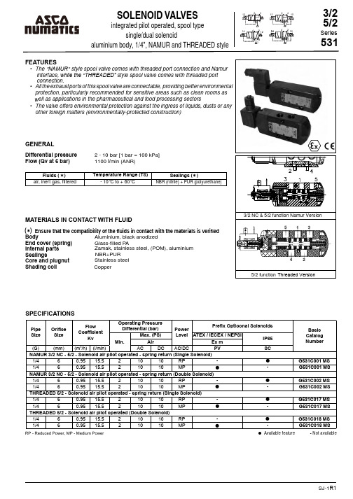
SJ-1R1Flow (Qv at 6 bar)1100 l/min (ANR)Fl uids ( ) Temperature Range (TS)Sealings ( )air, inert gas, fi ltered- 10°C to + 60°CNBR (nitrile) + PUR (polyurethane)MATERIALS IN CONTACT WITH FLUIDBody Aluminium, black anodized End cover (spring) Glass-fi lled P Alnternal partsZamak, stainless steel, (POM), aluminium Stainless steel Core and plugnutSealingsNBR+PUR Shading coil CopperSPECIFICATIONS● Available feature- Not available( ) RP - Reduced Power, MP - Medium Power•••• Ensure that the compatibility of the fluids in contact with the materials is verifiedPipe Size Orifice Size FlowCoefficientKvOperating PressureDifferential (bar)PowerLevel Prefix Optioonal SolenoidsBasic Catalog NumberMin.Max. (PS)ATEX / IECEX / NEPSIIP65Air Ex m(G)(mm)(m 3/h)(l/min)AC DC AC/DC PV SC NAMUR 3/2 NC - 5/2 - Solenoid air pilot operated - spring return (Single Solenoid)1/460.9515.521010RP -G531C001 MS 1/460.9515.521010MP -G531C001 MS NAMUR 3/2 NC - 5/2 - Solenoid air pilot operated - spring return (Double Solenoid)1/460.9515.521010RP -G531C002 MS 1/460.9515.521010MP -G531C002 MS THREADED 5/2 - Solenoid air pilot operated - spring return (Single Solenoid)1/460.9515.521010RP -G531C017 MS 1/460.9515.521010MP -G531C017 MS THREADED 5/2 - Solenoid air pilot operated (Double Solenoid)1/460.9515.521010RP -G531C018 MS 1/460.9515.521010MP -G531C018 MS••••ORDERING EXAMPLES:SERIES 531EXPLANATION OF TEMPERATURE RANGES OF SOLENOID VALVESValve temperature range The valve temperature range is determined by the selected seal material, the temperature range for proper operation of the valve and sometimes by the fluid ( e.g. steam )Operator ambient temperature rangeThe operator ambient temperature range is determined by the selected power level ( LP, RP, MP or BP ) and the ATEX safety codeTotal temperature rangeThe temperature range of the complete solenoid valvle is determined by the limitations of both temperature range aboveELECTRICAL CHARACTERISTICSCoil insulation class FElectrical safety IEC 335Standard voltages DC 24V - 48VAC 24V - 48V - 115V - 230V/50Hz(Other voltages and 60 Hz available on request)SJ-2R1ADDITIONAL OPTIONSELECTRICAL CONNECTIONSPrefix Connection SC Spade plug connector with cable gland DIN 43650, 11mm, industry standard B, for cables with an outer diameter from 6 to 8 mm (Type 01 / 03) PVMoulded - in cable, standard length 2m (Type 02 / 04)・Other pipe threads are available on request・Plug with visual indication and peak voltage suppression or with cable length of 2m, SC prefix only (Consult ASCO NUMATICS Ofices) ・Moulded-in cable, standard length 2m (Type 02 /04)Prefix OptionCoil TypeNorminal Power RatingOperator AmbientTemperatureRange (TS)(。
工业硅441和553 太阳能用
工业硅441和553 太阳能用下载提示:该文档是本店铺精心编制而成的,希望大家下载后,能够帮助大家解决实际问题。
文档下载后可定制修改,请根据实际需要进行调整和使用,谢谢!本店铺为大家提供各种类型的实用资料,如教育随笔、日记赏析、句子摘抄、古诗大全、经典美文、话题作文、工作总结、词语解析、文案摘录、其他资料等等,想了解不同资料格式和写法,敬请关注!Download tips: This document is carefully compiled by this editor. I hope that after you download it, it can help you solve practical problems. The document can be customized and modified after downloading, please adjust and use it according to actual needs, thank you! In addition, this shop provides you with various types of practical materials, such as educational essays, diary appreciation, sentence excerpts, ancient poems, classic articles, topic composition, work summary, word parsing, copy excerpts, other materials and so on, want to know different data formats and writing methods, please pay attention!工业硅441和553在太阳能行业的应用随着太阳能行业的迅猛发展,工业硅441和553作为关键原材料,在太阳能电池生产中扮演着重要角色。
SI-3003资料

Electrical CharacteristicsAbsolute Maximum RatingsEquivalent Circuit DiagramStandard Circuit DiagramExternal Dimensions (unit: mm)8Featuresq 3-terminal IC regulator with 0.8A output current q Voltage accuracy of ±2%q Low Dropout voltage 0.5V at I O 0.5A, 1V at I O 0.8Aq Built-in constant current type overcurrent, overvoltage and thermal protection circuits q TO-220 equivalent full-mold packageTerminal connections 1. V IN2. (NC)3. GND4. (NC)5. V Oa: Type No.b: Lot No.12345(Forming No. 1115)V IN V OGNDNotes:*1. Since P D (max) = (V IN –V O ) • I O =22(W), V IN (max) and I O (max) may be limited depending on operatingconditions. Refer to the Ta—P D curve to compute the corresponding values.*2. Refer to the dropout voltage.*3. IS1 rating shall be the point at which the output voltage V O (V IN =14V, I O =0.5A) drops to –5%.Co : Output capacitor (47 to 100µF, 50V)C 1,C 2 :Anti-oscillation capacitors (C 1: approx. 47µF, C 2: approx. 0.33µF). These are required for inductive input lines or long wiring. Tantalum capacitors are recommended for C 1 and Co, especially at low temperatures.D 1 : Protection diode. Required as protection against reverse biasing between input and output. (Recommended diode: Sanken EU2Z.)2*2*190.20.10.30.40.500.20.40.60.84321562134560Note on Thermal Protection Characteristics:The thermal protection circuit is intended for protection against heat during instantaneous short-circuiting. Its operation, including reliability, is not guaranteed for short-circuiting over an extended period of time.Output current I O (A)Output current I O (A)D r o p o u t v o l t a g e V D I F (V )s I o vs V DIF Characteristicss Line RegulationO u t p u t v o l t a g e V O (V )O u t p u t v o l t a g e V O (V )O u t p u t v o l t a g e V O (V )O u t p u t v o l t a g e V O (V )O u t p u t v o l t a g e V O (V )Input voltage V IN (V)Input voltage V IN (V)Input voltage V IN (V)s Load Regulations Rise Characteristicss Circuit Currents Thermal Protection CharacteristicsG r o u n d c u r r e n t l g (m A )s Overcurrent Protection Characteristicss Output Voltage Temperature CharacteristicsAmbient temperature Ta (ºC)Ambient temperature Ta (ºC)Output current I O (A)Operating temperature Ta (ºC)P o w e r D i s s i p a t i o n P D (W )s Ta—P D Characteristics。
维沙BY228-13标准氧化陶瓷晶体管稳定氧化陶瓷晶体管用户手册说明书
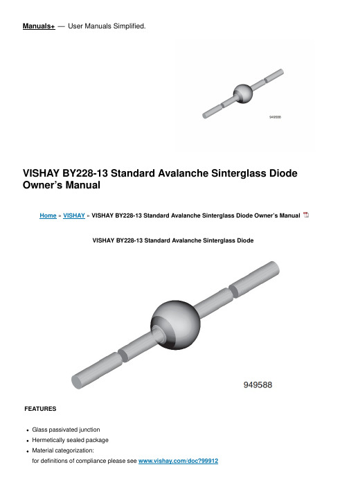
Manuals+— User Manuals Simplified.VISHAY BY228-13 Standard Avalanche Sinterglass Diode Owner’s ManualHome » VISHAY » VISHAY BY228-13 Standard Avalanche Sinterglass Diode Owner’s ManualVISHAY BY228-13 Standard Avalanche Sinterglass DiodeFEATURESGlass passivated junctionHermetically sealed packageMaterial categorization:for definitions of compliance please see /doc?99912APPLICATIONSHigh voltage rectificationEfficiency diode in horizontal deflection circuits DESIGN SUPPORT TOOLSDESIGN SUPPORT TOOLSPARTS TABLEPART TYPE DIFFERENTIATION PACKAGE BY228-13V = 1000 V; I = 3 A SOD-64 BY228-15V = 1200 V; I = 3 A SOD-64 ABSOLUTE MAXIMUM RATINGS (T = 25 °C, unless otherwise specified)PARAMETER TEST CONDITION PART SYMBOLVALUE UNITReverse voltage See electrical characteristics BY228-13V1000VBY228-15V1200VPeak reverse voltage, non rep etitive l = 100 µABY228-13VRSM1300VBY228-15VRSM1500VPeak forward surge current t = 10 ms, half sine wave IFSM50A Average forward current IF(AV)3A Junction temperature T140°CStorage temperature range Tstg -55 to +1 75°CNon repetitive reverse avalanc he energy l = 0.4 A E10mJR F(AV)R F(AV)ambRR Rpj (BR)R RMAXIMUM THERMAL RESISTANCE (T = 25 °C, unless otherwise specified)PARAMETER TEST CONDITION SYMBOL VALUE UNITJunction ambientOn PC board with spacing 25 mmRthJA70K/WELECTRICAL CHARACTERISTICS (T = 25 °C, unless otherwise specified)PARAMETER TEST CONDITION PART SYMBO LMIN.TYP.MAX.UNITForward voltageI = 5 AV –– 1.5VReverse currentV = 1000 V BY228-13I –25µAV = 1200 VBY228-15I –25µAV = 1000 V, T = 140 °CBY228-13I ––140µAV = 1200 V, T = 140 °CBY228-15I ––140µAReverse recovery tim e I = 0.5 A, I = 1 A, i = 0.25 Atrr ––2µsTotal reverse recovery time l = 1 A, – dI /dt = 0.05 A /µstrr ––20µsTYPICAL CHARACTERISTICS (Tamb = 25 C, unless otherwise specified)Fig. 1 – Typ. Thermal Resistance vs. Lead Lengthamb amb F FR RR RR j RR j RF R R F FFig. 2 – Forward Current vs. Forward VoltageFig. 3 – Max. Average Forward Current vs. Ambient TemperatureFig. 4 – Reverse Current vs. Junction TemperatureFig. 5 – Diode Capacitance vs. Reverse VoltageFig. 6 – Diode Capacitance vs. Reverse VoltagePACKAGE DIMENSIONS in millimeters (inches): SOD-64Contents1 Disclaimer2 Documents /Resources2.1 References3 Related PostsDisclaimerALL PRODUCT, PRODUCT SPECIFICATIONS AND DATA ARE SUBJECT TO CHANGE WITHOUT NOTICE TO IMPROVERELIABILITY, FUNCTION OR DESIGN OR OTHERWISE.Vishay Antitechnology, Inc., its affiliates, agents, and employees, and all persons acting on its or their behalf (collectively, “Vishay”), disclaim any and all liability for any errors, inaccuracies or incompleteness contained in any datasheet or in any other disclosure relating to any product.Vishay makes no warranty, representation or guarantee regarding the suitability of the products for any particular purpose or the continuing production of any product. To the maximum extent permitted by applicable law, Vishay disclaims (i) any and all liability arising out of the application or use of any product, (ii) any and all liability, including without limitation special, consequential or incidental damages, and (iii) any and all implied warranties, including warranties of fitness for particular purpose, non-infringement and merchantability.Statements regarding the suitability of products for certain types of applications are based on Vishay’s knowledge of typical requirements that are often placed on Vishay products in generic applications. Such statements are not binding statements about the suitability of products for a particular application. It is the customer’s responsibility to validate that a particular product with the properties described in the product specification is suitable for use in a particular application. Parameters provided in datasheets and / or specifications may vary in different applications and performance may vary over time. All operating parameters, including typical parameters, must be validated for each customer application by the customer’s technical experts.Product specifications do not expand or otherwise modify Vishay’s terms and conditions of purchase, including but not limited to the warranty expressed therein.Hyperlinks included in this datasheet may direct users to third-party websites. These links are provided as a convenience and for informational purposes only. Inclusion of these hyperlinks does not constitute anendorsement or an approval by Vishay of any of the products, services or opinions of the corporation,organization or individual associated with the third-party website.Vishay disclaims any and all liability and bears no responsibility for the accuracy, legality or content of the third-party website or for that of subsequent links.Except as expressly indicated in writing, Vishay products are not designed for use in medical, life-saving, or life-sustainingapplications or for any other application in which the failure of the Vishay product could result in personal injury or death.Customers using or selling Vishay products not expressly indicated for use in such applications do so at their own risk. Please contact authorized Vishay personnel to obtain written terms and conditions regarding products designed for such applications.No license, express or implied, by estoppel or otherwise, to any intellectual property rights is granted by this document or by any conduct of Vishay. Product names and markings noted herein may be trademarks of their respective owners.Documents / ResourcesVISHAY BY228-13 Standard Avalanche Sinterglass Diode [pdf] Owner's ManualBY228-13 Standard Avalanche Sinterglass Diode, BY228-13, Standard Avalanche SinterglassDiode, Avalanche Sinterglass Diode, Sinterglass Diode, DiodeReferencesVishay Intertechnology: Passives & Discrete Semiconductors/doc?32571/doc?86118/doc?91000/doc?99912Manuals+,。
伯乐焊材CHI

高强管道钢
API X65 X70 X80 X100-X110
EN L450MB L485MB L555MB
FOX CEL-FOX CEL+
FOX BVD RP
FOX EL 85-FOX CEL 85 G FOX BVD 85
FOX CEL-FOX CEL+
FOX BVD RP
FOX CEL 85-FOX CEL 85 G FOX BVD 90
Pipeshield 71 T8-FD
12, 18 12 - 17 13 - 19 13, 19
Pipeshield 71 T8-FD
12 - 18 14
Pipeshield 71 T8-FD
12 - 18 14 - 17
Pipeshield 71 T8-FD
12, 18 12 - 17 13 - 19 13, 19
FOX BVD RP
FOX CEL 75, FOX CEL 75 G FOX BVD 85
FOX CEL 85, FOX CEL 85 G
FOX EV Pipe
FOX EV Pipe FOX EV 60 Pipe
SG 3-P K-Nova Ni
FOX EV Pipe FOX EV 60 Pipe
SG 3-P K-Nova Ni
据当今最先进的工业特殊要求生产。 对于特定客户或特殊工艺要求,我们可提供相关文件、证书、 检验、包装与产品标识等。详细情况请与我们联系!
伯乐焊接特别领先于高温抗蠕变钢、不锈钢和镍基合金焊接 材料。相信凭借伯乐焊接80多年的经验与实践,我们可以成为 当今高要求工业用户的最佳合作伙伴。 您可以登录网站获得您附近的销售 伙伴。
天然气 4000 1016
AES 1235 品牌 BNS 产品名称 磁性安全传感器 型号 101170049说明书

DATASHEETDataOrdering dataNote (Delivery capacity)Phased-out product Product type description AES 1235101170049Article number (ordernumber)EAN (European Article4030661297118 Number)27-37-18-19eCl@ss number, version12.027-37-18-19eCl@ss number, version11.027-37-18-19eCl@ss number, version9.0EC001449ETIM number, version7.0EC001449ETIM number, version6.0Available until31.12.2023Approvals - StandardsCertificates BGcULusGeneral dataStandards BG-GS-ET-14BG-GS-ET-20EN IEC 62061EN ISO 13849-1EN IEC 60947-5-1EN IEC 60947-5-3EN IEC 60947-5-5EN IEC 60204-1EN IEC 60947-1Climatic stress EN 60068-2-3BG-GS-ET-14Enclosure material Glass-fibre reinforced thermoplastic, ventilated Gross weight240 gGeneral data - FeaturesStop-Category0Wire breakageYesdetectionCross-circuit detection YesFeedback circuit YesYesAutomatic resetfunctionReset afterYesdisconnection of supplyvoltageEarth connectionYesdetectionYesIntegral systemdiagnostics, statusNumber of LEDs12Number of normallyclosed (NC)1Number of normallyopen (NO)Number of undelayed2semi-conductor outputswith signaling functionNumber of safety2contactsNumber of signalling2outputsSafety classificationStandards EN ISO 13849-1EN IEC 61508Safety classification - Relay outputsdPerformance Level, uptoCategory3PFH value 1.00 x 10⁻⁷ /hNotice for max. 50,000 switching cycles/year and max. 80% contact load2Safety Integrity Level(SIL), suitable forapplications inMission time20 Year(s)Mechanical data20,000,000 OperationsMechanical life,minimumMounting Snaps onto standard DIN rail to EN 60715Mechanical data - Connection techniqueTerminal designations IEC/EN 60947-1Termination rigid or flexibleScrew terminals M20 x 1.5Cable section, minimum0.25 mm²2.5 mm²Cable section,maximumTightening torque of0.6 NmClipsMechanical data - DimensionsWidth22.5 mmHeight100 mmDepth121 mmAmbient conditionsDegree of protection ofIP40the enclosureDegree of protection ofIP54the mounting spaceDegree of protection ofIP20clips or terminalsAmbient temperature+0 ... +55 °CStorage and transport-25 °Ctemperature, minimumStorage and transport+70 °Ctemperature, maximumResistance to vibrations10...55 Hz, Amplitude 0.35 mm, ± 15 % Restistance to shock30 g / 11 msAmbient conditions - Insulation valuesRated impulse4 kVwithstand voltage UimpOvervoltage category IIIDegree of pollution2Electrical dataFrequency range50 Hz60 HzOperating voltage24 VAC -15 % / +10 %24 VDC -10 % / +20 %Ripple voltage10 %Thermal test current 6 ARated operating voltage24 VACRated operating voltage24 VDC20.4 VACRated AC voltage forcontrols, 50 Hz,minimum26.4 VACRated control voltage atAC 50 Hz, maximum20.4 VACRated AC voltage forcontrols, 60 Hz,minimum26.4 VACRated control voltage atAC 60 Hz, maximum20.4 VDCRated AC voltage forcontrols at DC minimumRated control voltage at28.8 VDCDC, maximum5 WElectrical powerconsumption0.1 ΩContact resistance,maximumin new stateNote (Contactresistance)Drop-out delay in case80 msof power failure,typically20 msDrop-out delay in caseof emergency, typically100 msPull-in delay atautomatic start,maximum, typically20 msPull-in delay at RESET,typicallyMaterial of the contacts,Ag-Ni 10 and 0.2 µm gold-plated electricalElectrical data - Safe relay outputsVoltage, Utilisation230 VACcategory AC-156 ACurrent, Utilisationcategory AC-15Voltage, Utilisation24 VDCcategory DC-136 ACurrent, Utilisationcategory DC-13Switching capacity,10 VDCminimum10 mASwitching capacity,minimum250 VACSwitching capacity,maximum8 ASwitching capacity,maximumElectrical data - Digital inputs10 … 30 VDCInput signal, HIGHSignal "1"0 … 2 VDCInput signal, LOW Signal"0"40 ΩConduction resistance,maximumElectrical data - Digital OutputVoltage, Utilisation24 VDCcategory DC-120.1 ACurrent, Utilisationcategory DC-12Electrical data - Relay outputs (auxiliary contacts) Switching capacity,24 VDCmaximumSwitching capacity,2 AmaximumElectrical data - Electromagnetic compatibility (EMC)EMC rating EMC-DirectiveIntegral system diagnosis (ISD)Note (ISD -Faults)The following faults are registered by the safety monitoring modules and indicated by ISD.Faults Failure of the safety relay to pull-in or drop-outFailure of door contacts to open or closeCross-wire or short-circuit monitoring of the switch connectionsInterruption of the switch connectionsFault on the input circuits or the relay control circuits of the safety monitoring moduleOther dataNote (applications)Safety sensorGuard systemNoteNote (General)Inductive loads (e.g. contactors, relays, etc.) are to be suppressed by means of asuitable circuit.Wiring exampleNote (Wiring diagram)The wiring diagram is shown with guard doors closed and in de-energised condition.To secure a guard door up to PL d and Category 3Monitoring 1 guard door(s), each with a magnetic safety sensor of the BNS rangeThe ISD tables (Intergral System Diagnostics) for analysis of the fault indications andtheir causes are shown in the appendix.Expansion of enable delay time: The enable delay time can be increased from 0.1 s to1 s by changing the position of a jumper link connection under the cover of the unit.The feedback circuit monitors the position of the contactors K3 and K4.Start push button: A start push button (NO) can optionally be connected into thefeedback circuit. With the guard door closed, the enabling paths are then not closeduntil the start push button has been operated.If only one external relay or contactor is used to switch the load, the system can beclassified in Control Category 3 to ISO 13849-1, if exclusion of the fault “Failure of theexternal contactor” can be substantiated and is documented, e.g. by using a reliabledown-rated contactor. A second contactor leads to an increase in the level of securityby redundant switching to switch the load off.If neither start button nor feedback circuit are connected, a jumper connection must bemounted between X1 and A1.Modification for 2 NC contacts: The safety monitoring module can be modified tomonitor two NC contacts by bridging the terminals A1 and X2. In this configuration, theshort-circuit detection becomes inoperative.Ordering codeProduct type description:AES 123(1)(1)56without start-up test6with start-up testDocumentsOperating instructions and Declaration of conformityAES 1235 / AES 1236(245.3 kB, 10.05.2019, Revision D)BG-test certificateAES and BNS - BG-GS-ET-14 - AES 1135 / AES 1136 / AES 1145 / AES 1146 / AES 1155 / AES 1156 / AES 1165 / AES 1166 / AES 1175 / AES 1176 / AES 1235 / AES 1236 / AES 1265 / AES 1266 / AES 1185(1.4 MB, 10.05.2019, Revision F)BG-test certificateAES - BG-GS-ET-20 - AES 1135 / AES 1136 / AES 1145 / AES 1146 / AES 1155 / AES 1156 / AES 1165 / AES 1166 / AES 1175 / AES 1176 / AES 1235 / AES 1236 / AES 1265 / AES 1266(738.9 kB, 10.05.2019, Revision D)UL CertificateAES / FWS / BNS / BN(415.3 kB, 01.08.2019)Wiring example (electr. wiring)AES 123x(19.6 kB, 10.05.2019)Wiring example (electr. wiring)AES 123x(19.7 kB, 10.05.2019)InfoAES 1135 / AES 1136 / AES 1165 / AES 1166 / AES 1185 / AES 1235 / AES 1236(34.3 kB, 30.06.2021)SISTEMA-VDMA library(659.5 kB, 23.03.2023)PicturesProduct picture (catalogue individual photo)ID: kaes1f09| 711.0 kB | .jpg | 265.642 x 529.167 mm - 753 x 1500 px - 72 dpi| 84.7 kB | .png | 74.083 x 147.461 mm - 210 x 418 px - 72 dpiWiring exampleID: maes1l11| 34.0 kB | .cdr || 143.8 kB | .jpg | 352.778 x 408.517 mm - 1000 x 1158 px - 72 dpiWiring exampleID: kaes1l41| 34.1 kB | .cdr || 139.5 kB | .jpg | 352.425 x 396.875 mm - 999 x 1125 px - 72 dpiK.A. Schmersal GmbH & Co. KG, Möddinghofe 30, 42279 WuppertalThe details and data referred to have been carefully checked. Images may diverge from original. Further technical data can be found in the manual. Technical amendments and errors possible.Generated on: 27/07/2023, 01:44。
- 1、下载文档前请自行甄别文档内容的完整性,平台不提供额外的编辑、内容补充、找答案等附加服务。
- 2、"仅部分预览"的文档,不可在线预览部分如存在完整性等问题,可反馈申请退款(可完整预览的文档不适用该条件!)。
- 3、如文档侵犯您的权益,请联系客服反馈,我们会尽快为您处理(人工客服工作时间:9:00-18:30)。
Semiconductor
SI5313-C / SI5313-C(B)
IRED
Features
• Colorless transparency lens type • φ5mm(T-13/4) all plastic mold type • Low power consumption
Please make sure that you consult with us before you use these AUK Corp. products in equipments which require high quality and / or reliability, and in equipments which could have major impact to the welfare of human life(atomic energy control, airplane, spaceship, transportation, combustion control, all types of safety device, etc.). AUK Corp. cannot accept liability to any damage which may occur in case these AUK Corp. products were used in the mentioned equipments without prior consultation with AUK Corp..
IFP
1
Reverse voltage
VR
4
Operating temperature range
Topr
-25∼85
Storage temperature range
Tstg
-30∼100
*2Soldering temperature
Tsol
260℃ for 10 seconds
*1.Duty ratio = 1/16, Pulse width = 0.1ms
*2.Keep the distance more than 2.0mm from PCB to the bottom of IRED package
(Ta=25℃)
Unit
mW mA A V ℃ ℃
Electrical / Optical Characteristics
Characteristic
Applications
• Infrared remote control and free air transmission systems with low forward voltage and comfortable radiation angle requirements in combination with PIN photodiodes or phototransistors.
Specifications mentioned in this publication are subject to change without notice.
KSD-O2Q001-000
4
Forward Current IF [mA]
Forward Voltage VF [V]
Fig. 3 IF – Ta
Forward Current IF [mA]
Fig.4 Spectrum Distribution
Relative Intensity [%]
Forward Current IF [mA]
-
∆λ
IF= 50mA
-
IR
VR=4V
-
θ1/2
IF= 50mA
-
*3. θ1/2 is the off-axis angle where the luminous intensity is 1/2 the peak intensity
Typ.
1.5 20 880 50 ±30
(Ta=25℃)
Max. Unit
The AUK Corp. products are intended for the use as components in general electronic equipment (Office and communication equipment, measuring equipment, home appliance, etc.).
1
元器件交易网
SI5313-C / SI5313-C(B)
Absolute Maximum Ratings
Characteristic
Symbol
Rating
Power dissipation
PD
180
Forward current
IF
100
*1Peak forward current
1.8
V
mW/Sr
-
nm
-
nm
10
uA
-
deg
KSD-O2Q001-000
2
元器件交易网
Characteristic Diagrams
Fig. 1 IF - VF
SI5313-C / SI5313-C(B)
Fig. 2 IE - IF
Radiant Intensity IE [mW/Sr]
Ambient Temperature Ta [℃]
Fig. 5 Radiation Diagram
Wavelength λ [nm]
Relative Radiant Intensity IE [%]
KSD-O2Q001-000
3
元器件交易网
SI5313-C / SI5313-C(B)
2.20~3.20
0.60 Max. 23.00 Min.
0.05 Typ.
2.54 Typ.
1.00 Min.
2.54 Typ.
1.00 Min.
12
5.60~6.00
12
5.60~6.00
0.55 Max.
0.55 Max.
KSD-O2Q001-000
PIN Connections 1. Cathode 2. Anode
Symbol Test Condition Min.
Forward voltage
VF
IF= 50mA
-
Radiant intensity Peak wavelength Spectrum bandwidth Reverse current
*3Half angle
IE
IF= 50mA
10
λP
IF= 50mA
Outline Dimensions
unit : mm
STRAIGHT TYPE
4.80~5.20
STOPPER TYPE : (B)
4.80~5.20
0.05 Typ. 0.60 Max.
8.70~9.10 1.40 Max.
0.05 Typ. 1.20 Min.
23.00 Min.
8.70~9.10 1.40 Max.