智能通讯控制器说明书
智能控制器软件使用说明书

5.1.3灯光模式复制
此选项可以将一个场景的灯光参数完全复制到当前场景,渐变与声控参数不能复制,如图10所示可将左边组复制到当前组。
2)红外码:在此可对红外码进行学习,有两种学习方式:
直接输入红外码值,点“写入”按钮进行写入。
点“学习”按钮,再用遥控器对准智能控制器显示屏的位置进行学习,学习成功后点“退出学习”按钮退出学习状态。
3)串口墙板1:在此可对墙板与组号进行学习关联,有两种学习方式:
直接输入墙板码值,点“写入”按钮进行写入;
制热模式时当室温度大于设定温度时,电子阀自动,并把空调置为空档,当室温下降到小于设定温度时电子阀再次打开,并自动调到设定风速档位。
送风模式时不对温度与电子阀进行关联控制,设定温度与当前温度均无效,空调随设定的档位持续工作。
制冷、制热模式必须正确设定,否则会导致空调工作不正常,若使用不带温度控制的墙板时,需设置为送风模式,否则可能会导致空调不工作。
5.1.2全局控制
全局控制所有参数设定界面如图8所示
图8
1)全局亮度:在此设置当前场景模式的默认全局亮度,默认亮度对该场景模式所有灯有效,每一路可调灯的亮度是由默认亮度与该路灯单独控制的亮度决定。选项如图9所示。
图9
2)开关模式:有两种模式可供选择:固定模式和开关模式。固定模式:按墙板上对应按键时,受控的各路灯打开,再次按下时保持不变;开关模式:按墙板上对应按键时,受控的各路灯打开,再次按下时受控的各路灯关闭。
2)全局控制
最新Mc800系列说明书
智能多媒体控制系统Intelligent Multimedia Control SystemMC800系列用户手册User’s Manual1第一章前言....................................................................................................3第二章系统硬件安装......................................................................................42-1、系统设备的接口说明 ......................................................................42-2、系统设备的连接 ..............................................................................82-3、电动屏幕的连接........................................................................................ 8第三章系统软件安装....................................................................................93-1、安装视频捕捉卡及其软件 ..............................................................93-2、安装电脑控制软件设置 .............................................................. 10第四章系统通讯协议................................................................................ 19第五章系统备份与恢复............................................................................ 24第六章常见问题........................................................................................ 256-1. 按控制面板“系统开”无法开机 ................................................... 256-2. 红外学习不成功或显示成功却不能遥控.................................... 266-3. 有些设备红外遥控不灵 ............................................................... 266-4. 投影机切换不灵 ........................................................................... 266-5. 关投影机出问题 ........................................................................... 272第一章前言本手册说明了您所使用的智能多媒体控制系统(IMCS)的硬件和软件的安装和功能设置。
智能控制器使用手册【范本模板】
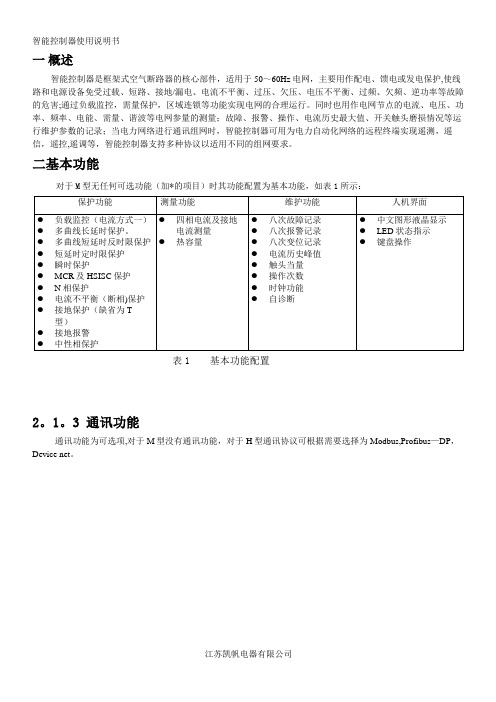
一概述智能控制器是框架式空气断路器的核心部件,适用于50~60Hz电网,主要用作配电、馈电或发电保护,使线路和电源设备免受过载、短路、接地/漏电、电流不平衡、过压、欠压、电压不平衡、过频、欠频、逆功率等故障的危害;通过负载监控,需量保护,区域连锁等功能实现电网的合理运行。
同时也用作电网节点的电流、电压、功率、频率、电能、需量、谐波等电网参量的测量;故障、报警、操作、电流历史最大值、开关触头磨损情况等运行维护参数的记录;当电力网络进行通讯组网时,智能控制器可用为电力自动化网络的远程终端实现遥测,遥信,遥控,遥调等,智能控制器支持多种协议以适用不同的组网要求。
二基本功能对于M型无任何可选功能(加*的项目)时其功能配置为基本功能,如表1所示:表1 基本功能配置2。
1。
3 通讯功能通讯功能为可选项,对于M型没有通讯功能,对于H型通讯协议可根据需要选择为Modbus,Profibus—DP,Device net。
2。
1.4增选功能选择增选功能为可选项,M型,H型都可以选择增选功能配置,不同增选功能代号与增选功能内容如表2所示.表2 增选功能配置表2。
1.5 区域连锁及信号单元的选择“区域连锁及信号单元"为可选项,M型、H型都可以选择信号单元的功能配置,当信号单元选择为S2,S3时,控制器具备区域连锁功能。
2.2 技术性能2.2。
1 适用环境工作温度:-10℃~+70℃(24h•内平均值不超过+35℃)储存温度:-25℃~+85℃安装地点最湿月的月平均最大相对湿度不超过90%,同时该月的月平均最低温度不超过+25℃,允许由于温度变化产生在产品表面的凝露.污染等级:3级。
(在和断路器装配在一起的情况下)安装类别:Ⅲ。
(在和断路器装配在一起的情况下)2。
2.2工作电源由辅助电源和电源互感器同时供电,保证负载很小和短路情况下控制都可以可靠工作。
控制器的供电方式有下面3种方式:a。
电源CT供电额定电流大于等于400A时,一次电流单相不低于0。
azbil CMC15G通讯控制器 说明书
No.CP-UM-5469C通訊控制器 CMC15G 多功能網關 使用說明書通訊連接篇POWER RUN CH1 RESET 1 2 CH 3 4ALM REC RS-232CLOADER USB CH2 11 12 13 1 2 EV 3 4 14 15 16 17 CH3RS-485CMC15G非常感謝您購買通訊控制器CMC15G。
本使用說明書中記述了安全、正確使用 CMC15G的必要事項。
對於承擔使用CMC15G的裝置的設計、維 護的工作人員請務必在閱讀理解本書的 基礎上使用。
此外,本使用說明書不只在安裝時,在 維護和故障維修時也是必不可少的。
請常備此手冊以供參考。
使用上的限制本産品是在一般設備上使用前提下開發、設計和製造的。
在有下列安全性要求的場合應用時,請在周全考慮了安全失效設計,冗餘設計及定期 維護檢查等系統和設備整體等的安全性的情況下使用。
・以人體保護爲目的的安全裝置 ・輸送設備的直接连接控制(運行停止等) ・航空設備 ・宇宙航天設備 ・原子能設備等 請勿把本産品用在與人身安全直接連接相關的用途上。
要求請確保把本使用說明書送到本産品使用者手中。
禁止擅自複印和轉載全部或部分本使用說明書的內容。
今後內容變更時恕不事先通知。
本使用說明書的內容,經過仔細審查校對,萬一有錯誤或遺漏,請向本 公司提出。
對客戶應用結果,本公司有不能承擔責任的場合,請諒解。
C 2007 Yamatake Corporation ALL RIGHTS RESERVED ○ⅰ本使用說明書的定位與CMC15G系列相關的使用說明書共有3冊。
請根據用途閱讀必要的使用說明書。
如果您手中無相關的使用說明書,請向本公司或代理店索取。
通訊控制器 CMC15G 多功能網關 資料編號 CP-UM-5463C 與CMC15G本體同包裝。
對安裝、設置上時的安全注意事項、安裝方法、電源、信號線接線等進行 說明。
通訊控制器 CMC15G多功能網關詳細篇 資料編號 CP-UM-5468C對本機的硬件及全部功能進行說明。
易联智能控制器产品说明说明书

easy800 with SmartWire-DTcontrols control circuit deviceseasily, quickly and efficiently.The new easy802 and easy806 with SmartWire-DT combine the f unctions of an easy800 with a direct connection to SmartWire-DT. Instead of wiring the inputs and outputs individually to control terminals, they are simply connected via a SmartWire-DT cable to the easy802/806 controllers. Programming is implemented as usual, in a ladder diagram using the easySoft-Pro programming software. The new programmable control relays combine the simplicity of two systems and maximize the efficiency of replacing standard control relays and point-to-point wiring.Connecting instead of wiring —ea s y800 programmable relayswith SmartWire-DTTimerSet: 15.00secAct: 04.34sec - ondelay -COM Quick to connect, simple to control and display With the easy800 you can quickly and efficiently connect and control circuit devices, manual motor protectors, contactors and input/output modules via SmartWire-DT . The connection of a remote text display via the serial programming interface facilitates thedisplay of texts and entry of values.easy806 with SmartWire-DTEaton is a registered trademark.All other trademarks are property of their respective owners.Eaton 1000 Eaton Boulevard Cleveland, OH 44122United States © 2014 Eaton All Rights Reserved Printed in USA Publication No. PA05013001E / Z14664January 2014ea s y800 with SmartWire-DTSupply Voltage Description Catalog No. (Style No.)24 Vdc Programmable relay with SmartWire-DT EASY802-DC-SWD (152901)24 Vdc Programmable relay with SmartWire-DT, four inputs, two of which can be used as outputs (transistor 24 Vdc, 0.1A)., easyNet on boardEASY806-DC-SWD (152902)AA separate 24 Vdc power supply is required to supply control power to these controllers.SmartWire-DTSmartWire-DT is a high-performance system that can be used to quickly and easily connect control components such as contactors, manual motor protectors, control circuit devices and digital and analog input/output modules. On the easy806 with integrated SmartWire-DT controller, up to 99 SmartWire-DT devices with up to 166 inputs/outputs can be connected. All required supply voltages, including those for the bus devices and 24 Vdc for the contactors, are provided directly with the flat 8-pole SmartWire-DT cable. This reduces wiring effort and troubleshooting, saving time and costs. For more information on SmartWire-DT , go to /smartwiredt.ea s ySoft-Pro The SmartWire-DT configurator (SWD-Assist) has been integrated with the easySoft-Pro programming software for easy800. Using the configurator tab, the SmartWire-DT line is created with all devices, and the SmartWire-DT devices are subsequently assigned with the operands. This can be undertaken manually or automatically as required. Switches and contacts are assigned to the inputs I17 to I99 and contactor coils and indicator lights to the outputs Q17 to Q99. Important inputs or outputs, such as those from manual motor protectors, make up the well-known easy800 marker ranges (optional marker bytes, marker words and double words). The operands can be used in the accustomed manner in the circuit diagram—simply easy!EASY802-DC-SWD AEASY802-DC-SWD features a POW power feeder for relaying power to the controller as well as the SmartWire-DT devices. A second AUX power feeder provides the connected contactors with 24 Vdc. The configuration of the SmartWire-DT devices is done with a touch of the “Configuration” button. LEDs provide feedback on the states of the device and the SmartWire-DT line. The serial interface serves for programming as well as the connection of a remote text display, touch panel or connection to the ethernet.EASY806-DC-SWD A In addition to the functionality of the EASY802-DC-SWD, the EASY806-DC-SWD also features four fast inputs (5 KHz). Two of the four inputs can also be configured as fast outputs (5 KHz) (transistor 24 Vdc, 0.1A). In addition to the inputs/outputs on EASY806-DC-SWD, there is a connection option to the easyNet. With this, up to 1360 inputs/outputs can be connected.。
控制器的通信接口说明书

控制器的通信接口说明书一、概述本文档旨在详细介绍控制器的通信接口,包括接口类型、接口参数和接口使用方法等。
控制器是一种重要的自动控制设备,主要用于工业自动化、家居自动化、机器人控制等领域。
通信接口是控制器与其他设备进行数据交换的重要途径之一,因此,掌握控制器通信接口的使用方法非常必要。
二、接口类型控制器的通信接口类型有多种,主要包括以下几种:1.串口接口串口接口是控制器最常用的通信接口之一,它具有通信距离短、速度快、可靠性高等特点。
常见的串口接口有RS232、RS485、TTL等。
其中,RS485接口是工业自动化领域中使用最广泛的一种串口接口,它支持多点连接,可以同时与多个设备进行通信。
2.以太网接口以太网接口是控制器现代化的通信接口之一,它具有通信速度快、连接距离远、传输数据量大等特点。
以太网接口通常采用TCP/IP协议进行数据传输,可以同时与多个设备进行通信。
3.无线接口无线接口是控制器近年来广泛采用的通信接口之一,它具有无线连接、方便布线、适用于移动设备等特点。
常见的无线接口有蓝牙、WIFI、Zigbee、LoRa等。
其中,蓝牙接口适用于短距离通信,WIFI接口适用于室内大范围通信,Zigbee接口适用于低功耗设备通信,LoRa 接口适用于远距离通信。
三、接口参数控制器的通信接口参数是使用接口时需要注意的重要事项之一,包括接口类型、波特率、数据位数、校验位和停止位等,这些参数的设置直接影响到接口的通信效果。
下面以RS485接口为例介绍常见的接口参数设置方法:1.波特率波特率是指每秒钟传输的比特数,它是RS485接口常见的一个重要参数。
常见的波特率有2400bps、4800bps、9600bps、19200bps、38400bps等。
波特率的设置应该根据实际情况来确定,一般在使用过程中可以逐步增加,直至数据传输速度达到最佳状态。
2.数据位数数据位数是指每个数据字节中的二进制位数,常见的数据位数为7位或8位,一般默认为8位。
unit3 智能控制器说明书

unit3 智能控制器说明书
智能控制器是一种用于控制和管理各种设备和系统的装置。
它
通常具有自动化、智能化和远程控制的功能,能够实现对设备的精
确控制和监控。
智能控制器通常应用于工业自动化、建筑物管理系统、智能家居等领域。
下面我将从多个角度全面介绍智能控制器的
说明书内容。
首先,智能控制器说明书通常包括产品的基本信息,如型号、
规格、外观尺寸、工作原理等。
这些信息可以帮助用户了解产品的
基本特性和适用范围。
其次,说明书会详细介绍智能控制器的安装和操作步骤。
包括
安装环境要求、安装方法、接线方式、开机操作、参数设置等内容。
这些内容对用户正确使用和维护智能控制器至关重要。
另外,智能控制器说明书还会对产品的功能特点进行详细说明,包括各种传感器、执行器的连接方式、通讯协议、远程监控等功能。
用户可以通过说明书了解产品的功能优劣势,以便更好地应用和操作。
此外,说明书通常也会包括故障诊断与排除方法,以及维护保养等内容。
这些内容对于用户在日常使用中遇到问题时能够及时处理故障,保证设备的正常运行具有重要意义。
最后,智能控制器说明书还可能包括产品的技术参数、安全注意事项、售后服务政策等内容,以帮助用户更全面地了解产品并获取相关的支持和服务。
综上所述,智能控制器说明书是用户了解、安装、操作和维护智能控制器的重要参考资料,它的内容应该全面、详细、准确,以确保用户能够正确、安全地使用智能控制器,同时也为售后服务提供了重要的依据。
智能控制器访问和操作指南说明书
85464609161011Operating InstructionsIntelligent ControllerAccess and Operation by Web BrowserBefore operating the unit, read these operating instructions thoroughly and keep them for future reference.Model No. CZ-256ESMC1U1006 Kadoma, Kadoma City, Osaka, JapanCV6233189659CONTENTSCONTENTS1. COMPUTER ENVIRONMENT REQUIREMENTS (1)2. LOG-IN (1)3. SCREEN DISPLAY AND OPERATION (2)3-1. [Each Tenant] Screen (2)3-2. [Each Tenant Details] Screen (5)3-3. [All Units] Screen (5)3-4. Distribution Ratio/Usage: Data Download Screen (6)3-5. Alarm Log Screen (7)3-6. Mail Send Log Screen (9)3-7. Program Timer Screen (10)3-8. Tenant Holiday/Timer Special Day Screen (12)3-9. Prohibit Remote Control Screen (13)3-10. WEB Settings Screen (14)3-10-1. Server details (16)4. SUPPLEMENTARY INFORMATION (18)Note:This equipment has been tested and found to comply with the limits for a Class B digital device, pursuant to part 15 of the FCC Rules. These limits are designed to providereasonable protection against harmful interference in a residential installation. Thisequipment generates, uses and can radiate radio frequency energy and, if not installed andused in accordance with the instructions, may cause harmful interference to radiocommunications. However, there is no guarantee that interference will not occur in aparticular installation. If this equipment does cause harmful interference to radio or televisionreception, which can be determined by turning the equipment off and on, the user isencouraged to try to correct the interference by one or more of the following measures:•Reorient or relocate the receiving antenna.•Increase the separation between the equipment and receiver.•Connect the equipment into an outlet on a circuit different from that to which the receiver is connected.•Consult the dealer or an experienced radio/TV technician for help.FCC Caution: To assure continued compliance, follow the attached installation instructions.Any changes or modifications not expressly approved by the party responsible forcompliance could void the user's authority to operate this equipment.ACCESS AND OPERATION BY WEB BROWSER ACCESS AND OPERATION BY WEB BROWSERAccessing the Intelligent Controller from your computer allows you to monitor/operate air-conditioningequipment using a Web browser.1. COMPUTER ENVIRONMENT REQUIREMENTSIn order to use the web browser of your computer to connect to the Intelligent Controller and monitor/operateair-conditioning equipment, the following environment requirements must be met.Supported browser : I nternet Explorer 6.0 or laterJava applet : S un Microsystems Java Plugin Ver 1.4.2 or laterScreen resolution : 1024 × 768 recommended2. LOG-INTo log in to the Intelligent Controller, enter the following into the address bar of the web browser:h ttp://[Intelligent Controller address]/SACWWW/index_[language code].aspFor example, if the Intelligent Controller address is 192.168.0.2 and you want to connect to the English page, enter:h ttp://192.168.0.2/SACWWW/index_en.aspIf the DNS is used and ID name (device name) of the Intelligent Controller is “WindowsCE0”, enter: http://WindowsCE0/SACWWW/index_en.asp.The language codes are as follows.Enter the user ID and password set for the Intelligent Controller to log in.Shows the site name that was set for Intelligent Controller.Enter the user ID that was set for Intelligent Controller.Enter the password that was set for Intelligent Controller.Click the Login button.3. SCREEN DISPLAY AND OPERATION 3-1. [Each Tenant] ScreenAfter you log in to the Intelligent Controller, or when you use the menu to select [1. Status/Control :1. Each tenant], a screen such as shown below appears. (Screen details may differ depending on the user logged in.)NewbuttonUpdates the screen to the latest information.Menu(The menu may differ depending on the user logged in. The following menu appears when logged in as an administrator.) Lets you select one of the following screens.★Administrator Menu★Special User Menu★General User MenuTenant listShows the indoor unit and tenant structure currently accessed by the Intelligent Controller in a list. Select indoor units by clicking different parts of the list.Clicking on the part highlighted in the screen example above will select the individual indoor unit, while clicking on the tenant name (Tenant001, Tenant002, etc. in the example) will select all indoor units for that tenant. Clicking on the top of the list (Tenant in the example) will select all indoor units of the site.Only the tenants that can be operated by the user permission used to log in (administrator, special, general) are displayed. Icon display areaShows icons for indoor units connected to the Intelligent Controller.Clicking on an icon whose frame is shown in reverse will select that unit. Clicking on a tenant name will select that tenant.Notification columnShows information about the connection status of web browser and Intelligent Controller, etc. Alarm code displayShows the alarm code as a tooltip when the cursor is moved over the icon of the indoor unit for which the alarm is occurring. Site nameThe “Site name” set in the Intelligent Controller appears. ⑧ Remote control windowShows the Remote control window. When this window has been closed, clicking on the indoor unit or making another selection will bring it up again.A Status/Control screen sectionShows the status of the indoor unit and the operation condition. When a control operation is performed, the background color of the respective field changes and the Send button becomes available. Clicking the Send button will send all operation steps performed up to this point to the Intelligent Controller. If you instead click the Cancel button or perform a step such as selecting another indoor unit, operation steps performed up to this point will be canceled.ERemote control windowB Control sectionShows controls for possible operation steps such as start/stopswitching, operation mode selection, temperature selection, fanC Send buttonSends the changes made to theIntelligent Controller.D Cancel buttonCancels the changes made.E CHECK buttonsUsed to check the timer setting and remote control prohibitionsetting status.(See “3-7. Program Timer Screen” and “3-9. Prohibit RemoteControl Screen”.)Clicking the Return button will return the display to theprevious screen.Remote control window for general user3-2. [Each Tenant Details] ScreenWhen you use the menu to select [1. Status/Control : 2. Each tenant details], a screen such as shown below appears. (Screen details may differ depending on the user logged in.) Operation principles for this screen are similar to those of the “3-1. [Each tenant] screen”.3-3. [All Units] ScreenWhen you use the menu to select [1. Status/Control : 5. All units], a screen such as shown below appears.(Screen details may differ depending on the user logged in.) A maximum of 256 indoor units are displayed in1 screen. Operation principles for this screen are similar to those of the “3-1. [Each tenant] screen”.3-4. Distribution Ratio/Usage: Data Download ScreenWhen you use the menu to select [3. Distrib. ratio/Usage : 3. Download] while logged in as an administrator,a screen such as shown below appears.You can download files by selecting them and clicking the “Download” button.A cut-off data file appears for each piece of cut-off data that appears on the Intelligent Controller unit. Beaware, however, that the dates that appear on the Intelligent Controller unit appear as file names on this screen.For example, cut-off data that appears as “01/Apr-30/Apr” on the Intelligent Controller will appear as“20070401-200704301.csv” on this screen.When the following message appears after clicking the “Download” button, select “Open” or “Save”.•“Open” ........ Open the selected CSV file using spreadsheet software.•“Save” ......... Select a folder and save the CSV file.3-5. Alarm Log ScreenWhen you use the menu to select [4. Maintenance/Test Run : 2. Alarm log] while logged in as anadministrator or special user, a screen such as shown below appears.When an indoor unit is selected in the tree section, the previous 14 occurrences are displayed.(Same as the display on the Intelligent Controller.)“I/D alarm log”, “O/D comm. error log”, and “Adaptor alarm log” can be selected from the drop-down list.[O/D comm. error log] logs the history of errors in communication between the outdoor unit and the Intelligent Controller or the communication adaptor.[Adaptor alarm log] logs the history of warnings as determined by the Intelligent Controller or the communication adaptor.(Duplicate adaptor addresses, communication error between the Intelligent Controller and adaptor, etc.)3-6. Mail Send Log ScreenWhen you use the menu to select [4. Maintenance/Test Run : 4. Sent mail log] while logged in as an administrator, a screen such as shown below appears.No.The entry numbers for the sent mail log. With a maximum of 20 (No. 1 to 20) possible entries, the newest entries appear at the top of the list. When the number of entries exceeds 20, entries are deleted starting with the oldest. As up to three mail recipients can be specified, up to three log entries can be recorded for one alarm occurrence.Rslt“OK” appears when an alarm mail is sent properly, and “NG” appears when sending fails.Send T.The date and time the alarm mail was sent (or sending was attempted).ToThe recipient address the alarm mail was sent to. If the address is too long, only part of the address may appear.Unit nameThe name of the indoor unit for which the alarm occurred.Alarm codeThe code for the alarm that occurred.Stat“Occurrence” appears when a notification of an alarm occurrence is sent, and “Restoration” appears when a notification of an alarm restoration is sent.AddressThe address of the indoor unit for which the alarm occurred.The address follows the format, “adaptor number - link number - system (outdoor) number - indoor number”. When a test mail is sent, “TEST_MAIL” appears.⑧3-7. Program Timer ScreenWhen you use the menu to select [6. Auxiliary settings : 3. Program timer] while logged in as anadministrator, or use the “CHECK” button for timer operation in the remote control window, a screen such as shown below appears. (As non-administrator users can only confirm settings and not configure them, the “Cancel” and “Send” buttons only appear when logged in as an administrator.)When the daily timer number is selected in the tree section, the current setting status is displayed.Click the desired setting item, and you can select the setting from the drop-down list as shown below.Drop-down lists are also displayed for the weekly timer in the same way as the daily timer number.Tree section“Cancel”/”Send” buttonsYou can only configure daily timer settings one number (D1, D2, etc.) at a time. If you attempt to switch to D2 settings in the middle of configuring D1 settings, for example, the message “Send for each daily timer.” appears.In such a case, apply or cancel the current settings by clicking the “Send” or “Cancel” button, respectively, before configuring the next daily timer number.For details on the settings, refer to the operation manual for the Intelligent Controller.The “Check RC prohib.” button appears in the previous page when logged in as an administrator or special user. When you click on this button, a screen such as shown below appears.3-8. Tenant Holiday/Timer Special Day ScreenWhen you use the menu to select [6. Auxiliary settings : 4. Ten.Ho/TimerSp.Day] while logged in as an administrator, a screen such as shown below appears.Tree section “Cancel”/”Send” buttons“Copy” buttonYou can only configure tenant holiday/timer special day settings one tenant at a time. If you attempt to switch to Tenant002 settings in the middle of configuring Tenant001 settings, for example, the message “Send for each tenant.” appears.In such a case, apply or cancel the current settings by clicking the “Send” or “Cancel” button, respectively, before configuring the next tenant.To copy changed settings, click the “Send” button and apply the settings before copying.For details on the settings, refer to the operation manual for the Intelligent Controller.3-9. Prohibit Remote Control ScreenWhen you use the menu to select [6. Auxiliary settings : 5. Prohibit R/C] while logged in as an administrator, or click the “CHECK” button for prohibit remote control in the remote control window, a screen such as shown below appears. (As non-administrator users can only confirm settings and not configure them, the “Cancel” and “Send” buttons only appear when logged in as an administrator.)For details on the settings, refer to the operation manual for the Intelligent Controller.3-10. WEB Settings ScreenWhen you use the menu to select [6. Auxiliary settings” : 10. WEB settings] while logged in as an administrator, a screen such as shown below appears.For details on the settings, refer to the operation manual for the Intelligent Controller.Input values have the following restrictions.Setting ItemInput Range Input Character LimitationsSite nameUp to 40 characters One-byte “=” is prohibitedIP address (each block ) Numbers 0 to 255“0.0.0.0” and “255.255.255.255” are prohibitedSubnet mask Default GatewayDNS (Primary, Secondary) WINS (Primary, Secondary) Numbers 0 to 255“0.0.0.0” is prohibitedDevice Name Alphanumeric characters, “–”, and “_” Up to 15 characters First character must be alphabetic character.“-” and “_” are prohibited as ending charactersSender's SMTP Symbols are “@” “.” “_” “:“ onlySender's account “=“ is prohibitedRecipient account 1 to 3Up to 40 alphanumericcharacters and symbolsTo [3.10.1. Server details] screen“Cancel”/”Send” buttonsIf a value that is outside the input range or input limitations is set, the window below appears.If the network settings have been changed when the “Send” button is clicked, the window below appears. Always check there is no problem restarting the Intelligent Controller unit.When “YES” is clicked for submission, the screen changes as shown below, and the Intelligent Controller unit restarts.When a mail test is sent, the window below appears when the mail settings have been changed.In this case, either click the “Send” button to enable the mail setting changes or click the “Cancel” button to disable the changes, and then send the mail test again.If the Intelligent Controller unit is processing (check configuration, cut-off, backup, etc.), this screen cannot be displayed or updated, mail test cannot be sent, and setting change “Send” cannot be performed. If the Intelligent Controller unit is displaying the initial setting screen (main menu 5) or the Settings screen (main menu 6), setting change “Send” cannot be performed. In either case, the following window appears.3-10-1. Server detailsWhen you click the “Server details” button from the [WEB settings] screen, a screen such as shown below appears.For details on the settings, refer to the operation manual for the Intelligent Controller.To [3-10-1-1 Receiving server settings] screenInput values have the following restrictions.Setting Item Input RangeInput Character LimitationsPort number Numbers 0 to 999999 User ID PasswordUp to 50 alphanumeric characters and symbols3-10-1-1. Receiving server settingsWhen you click the “Receiving server settings” button from the [Server details] screen, a screen such as shown below appears.For details on the settings, refer to the operation manual for the Intelligent Controller.Input values have the following restrictions.Setting Item Input RangeInput Character Limitations Recv. server address (POP3) Up to 40 alphanumeric characters and symbolsSymbols are “@” “.” “_” “:” only User ID Password Up to 50 alphanumeric characters and symbolsPort number Numbers 0 to 999999SUPPLEMENTARY INFORMATION4. SUPPLEMENTARY INFORMATION■ When connecting the Intelligent Controller via Internet, consider implementing network security measures, such as a firewall.■ Error MessagesErrorCauseRemedySystem configuration change!(when logged in with Administrator privileges)The system configuration of the Intelligent Controller has changed. This is a warning message. Wait a moment and resume operation.Intelligent Controller is nowprocessing, please wait. Please try later.The Intelligent Controller is applying settings. Access from the Web is heavy.If configuring settings with the Intelligent Controller, switch to a non-settings screen (such as screen 1-n).Wait a moment and resume operation.Communication errorThe Intelligent Controller was turned off whileconnected, or a cable was unplugged or the network failure.Try the operation again.Verify that the Intelligent Controller is turned on, and that the network wiring connections are correct.Invalid user IDThe entered user ID is different from the user ID registered on the Intelligent Controller.Verify the user ID that was registered to the Intelligent Controller.Wrong passwordThe entered password is different from thepassword registered on the Intelligent Controller.Verify the password that wasregistered to the Intelligent Controller.All Stop!All units were forced to stop.Do not operate until unit operation resumes.The external all stop input is switched on for the Intelligent Controller unit.When the external all stop input is changed to OFF, the messagedisappears. After changing to OFF, wait for the message to disappear.DC1011-11111 Printed in Japan。
- 1、下载文档前请自行甄别文档内容的完整性,平台不提供额外的编辑、内容补充、找答案等附加服务。
- 2、"仅部分预览"的文档,不可在线预览部分如存在完整性等问题,可反馈申请退款(可完整预览的文档不适用该条件!)。
- 3、如文档侵犯您的权益,请联系客服反馈,我们会尽快为您处理(人工客服工作时间:9:00-18:30)。
声明: 1、 本使用手册版权及解释权为丹东华通测控公司所有,未经许可,不得擅自翻印。 2、 本使用说明仅针对于 2000R+TCP 产品,对于在此以前的产品不可使用.如果用于其它设
备,造成的一切损失,丹东华通测控有限公司不承担任何经济责任,特此声明。
2005 年 12 月 2008 年 03 月 2008 年 07 月
MODBUS TCP/IP 从站
下发帧数 通讯延迟 重发次数 采集比例
子站数据 刷新时间
遥测总点 遥脉总点 遥信总点 遥控总点
每个 COM 口最大可配置下发数据总帧数: 遥测帧:64;遥脉帧:32;遥信帧:32;
20-100 mS 可选 默认为 25 mS 注:主站等待子站返回通讯数据的时间。
0/1/2/3/4/5/6 可选 默认为 1,0 为不重发 注:主站在“300mS”内未得到子站返回数据。
网络通讯控制器也称“通讯管理机”或“DPU”,其具有多个下行通讯接口及一个或 多个上行网络接口,相当于一台小型的监控计算机,用于将一个变电所内所有智能监控/保 护装置的通讯数据整理汇总后,实时上送上级主站系统(监控中心后台机和 DCS),完成遥 信、遥测.另一方面接收后台机或 DCS 下达的命令,并转发给变电所内智能电力监控单元, 完成对厂站内各开关设备的分、合闸远方控制或装置的定值整定,实现遥控和遥调。同时它 还配备了多个串行接口以便与厂站内其它智能设备进行通讯。
100M/Ack LED
10M/Ack LED
与主站联结方式:如果直接用网线与 PC 机连接,应采用的接法为一端为 T568A, 另一端为 T568B。如果通过网络集线器或网络交换机组网,网线两头接法应同为 T568A 或 T568B,常见的是 T568B 的接法。示意图如下
主站侧
2000R+TCP 侧
2000R+TCP 网络通讯控制器是一种新型变电站自动化信息综合管理单元,适用于各种 电压等级,不同规模,不同功能需求的变电站自动化系统。其作为变电站内的通信服务器, 既可用于变电站内智能装置的通信规约转换装置,也可用于电能计量管理系统中作为子站, 用来接入变电站内的智能仪表,完成变电站内的综合信息采集、控制和管理工作。
⑤
孔侧/母头)
5
2000R+TCP 使用说明书 V1.58 2.6.4 2000R+TCP 技术指标
丹东华通测控有限公司
网络接口 COM1 COM2 COM3 COM4 COM5 COM6 COM7 COM8 NET1 NET2
接线方式 通讯速率 通讯协议
RS-485, RS-232 可选
默认为:RS-232
端子 1 : N/A 端子 2 : N/A 端子 3 : A+ 端子 4 : B端子 5 : S.G.(屏蔽地)
1
5
(5 个端子,端子间距 3.81mm)
2.6.2 NET1~NET2 以太网接口(RJ-45 TCP/IP)
12345678
管脚 1 : T+ 管脚 2 : T管脚 3 : R+ 管脚 6 : R-
遥信采集比例:0-99; 遥测采集比例:0-99; 遥脉采集比例:0-99; 0 为不采集; 对于每个 COM 口(主站/波特率:9600)
● 遥信比例=6,遥测比例=3,遥脉比例=1 ◆ COM 口带子站数量=8 个时数据刷新周期 ☆ 遥信:1S;☆ 遥测:2S;☆ 遥脉:6S; ◆ COM 口带子站数量=12 个时数据刷新周期 ☆ 遥信:1.5S;☆ 遥测:3S;☆ 遥脉:9S; ◆ COM 口带子站数量=16 个时数据刷新周期 ☆ 遥信:2S;☆ 遥测:4S;☆ 遥脉:12S; ◆ COM 口带子站数量=24 个时数据刷新周期 ☆ 遥信:3S;☆ 遥测:6S;☆ 遥脉:18S; ◆ COM 口带子站数量=32 个时数据刷新周期 ☆ 遥信:4S;☆ 遥测:8S;☆ 遥脉:24S;
★ 免费提供 2000R+TCP 计算机配置软件,通过设置软件,可以任意配置 COM1~8 口的 PDM 仪表的遥测、遥脉、遥信、遥控数据读取仪表地址、寄存器数据、数据长度等, 并可以将 COM1~8 口的数据配置到以太网口(顺序由用户确定),并可上载、下载、 保存、打开相关配置,使用极为方便、灵活。
8 路 RS-485/232 串行通讯口 2 路 10/100M 自适应以太网口
为了适应这种需求,我们开发出了 2000R+TCP 网络通讯控制器,它采用运算能力强大 的 32 位工业控制 CPU,以及实时性高,可靠的实时多任务 LINUX 嵌入式操作系统做为系 统平台。它具有运行可靠,抗干扰能力强,响应速度快,易于扩展,易于调试,具有子站节 点合并及强大而灵活的数据组态功能,可实现 485/422/232 到以太网的数据转换功能,其下 行通讯口采用标准的 MODBUS RTU 通信规约,上行通讯网络既可以采用以太网(MODBUS TCP/IP),也可以采用 RS-485/232 总线;当地的监控主站,远方调度的具体要求在后台设 置软件进行设置即可通信,2000R+TCP 网络通讯控制器基本型有 2 个以太网口,8 个串口, 1 个 232 维护口,每个通信口均可接入不同数量的具有 MODBUS 规约的智能型产品。
★ 上行通讯接口(NET1~2 或 RS-232/485 可选);支持多种标准协议 CDT(DL 451-91)、 IEC-60870-5-101/103、ModBus 等可选,并可定制各种通讯协议;可驳接光缆或调制 解调器,实现数据远传;
★ 小型化外观(483*44*185mm,标准 1U 机箱)、盘面开孔安装方式及宽范围交直流通 用电源(AC/DC 85-255V);安装和维护极为便利,更符合低压智能化配电的要求;
4
2000R+TCP 使用说明书 V1.58
丹东华通测控有限公司
2.6 接线端口描述
2.6.1 Com1~Com8 通讯口(RS-485/RS-232)
RS-232(3 线)端子定义
端子 1 : RxD 端子 2 : N/A 端子 3 : TxD 端子 4 : N/A 端子 5 : S.G.(屏蔽地) RS-485(2 线) 端子定义
2.6.3 维护端口(RS-232) (用于系统维护及数据监视)
针 1 : DCD 针 2 : RxD 针 3 : TxD 针 4 : DTR 针 5 : S.G. (信号地)
与主站联结方式:RS-232 直联。示意图如下
①
主站侧
② ③
(DB9 为
④
针侧/公头) ⑤
①
② ③
2000R+TCP 侧
④
(DB9 为
300/600/900/1200/2400/4800/9600/19200/38400 可选
默认为:9600
MODBUS 主站
MODBUS
支持:01,02,03,04,05,06,10 功能码 主/从站 可选
子站数量 每个 COM 口最大可带 32 个子站设备
主站 同左
RJ45 TCP/IP 10/100M 自适应
d、工作环境:工作温度: -20℃~60℃; 存储温度: -40℃~ 85℃; 相对湿度: 5%~95%不结露;
2.3 外型尺寸
2000R+TCP 产品外型尺寸图
2000R+TCP 产品开孔尺寸图 3
2000R+TCP 使用说明书 V1.58 2.4 硬件框图
丹东华通测控有限公司
2.5 硬件描述
1. CPU : ARM7 Engine CPU ,ES3200. 2. Flash : 8M Bytes for Application program. 3. Main Memory : 16M Bytes. 4. Watch Dog Reset : Disable/Enable 0.7 Sec. 5. EtherNet Interface : RJ45 Phone Jack x2. 6. Com Port: RS-485/RS-232 Com Port x8. 7. Build-in selectable setup switch to set Com port mode. 8. On board Beeper. 9. Real Time Clock. 10. LED Indicator : Power x1,Run x1 ,Net (10Mx1,100Mx1) ,Com x8. 11. Debug Port : CPU Build in. 12. Input Power : AC/DC 85-255V. 13. Power Consumption : 5W.
★ 具有前置机功能,可将下行口 COM1~8 所接各从站设备的数据高速采集到 2000R+内, 同时对所据采集的数据进行自动归纳、整理和计算,并可根据用户要求按顺序排列;上 行以太网口可按各种通讯协议上送到主站或做为一个从站由主站来访问。
★ 下行通讯接口(COM1~8)为 RS-485 通讯接口;标准 MODBUS RTU 通讯协议;波 特率 1.2 ~ 19.2KBit/S 可选;每个通讯口在 1.2 公里内最多可连接 32 台 PDM 系列仪表 (8 个通讯口最大共可连接 256 台 PDM 仪表);
2000R+TCP
智能型网络通讯控制器
产品使用说明书
(版本号:V1.58)
2000R+TCP 使用说明书 V1.58
目
录
丹东华通测控有限公司
一、总体概述 —————————————————————————— 1 二、产品简介 —————————————————————————— 2 2.1 性能简介 —————————————————————————— 2 2.2 技术指标 —————————————————————————— 3 2.3 外型尺寸 —————————————————————————— 3 2.4 硬件框图 —————————————————————————— 4 2.5 硬件描述 —————————————————————————— 4 2.6 接线端口描述 ———————————————————————— 5 三、2000R+TCP 的典型应用 ———————————————————— 7 四、2000R+TCP 管理软件概述 ——————————————————— 8 五、关于 2000R+TCP 的数据监视 ————————————————— 23 六、关于 2000R+TCP 的双机(冗余)使用—————————————— 26 七、2000R+TCP 的通讯信息表 ——————————————————— 28 八、2000R+TCP 的设备配件 ———————————————————— 30 九、2000R+TCP 的基本常识 ———————————————————— 31 十、2000R+TCP 的 V1.58 升级备忘录 ———————————————— 34