Intro1_M03_getting_started
ADLRAN ATLAS 800PLUS 使用手册说明书

iv
Affidavit Requirements for Connection to Digital Services • An affidavit is required to be given to the telephone company whenever digital terminal equipment
901 Explorer Boulevard P.O. Box 140000
Huntsville, AL 35814-4000 (256) 963-8000
© 2000 ADTRAN, Inc. All Rights Reserved.
Prinns require that in this manual the following information be provided to the customer:
6. This unit contains no user-serviceable parts. 7. The following information may be required when applying to your local telephone company for
leased line facilities.
without encoded analog content and billing protection is used to transmit digital signals containing encoded analog content which are intended for eventual conversion into voiceband analog signals and transmitted on the network. • The affidavit shall affirm that either no encoded analog content or billing information is being transmitted or that the output of the device meets Part 68 encoded analog content or billing protection specifications. • End user/customer will be responsible for filing an affidavit with the local exchange carrier when connecting unprotected customer premise equipment (CPE) to 1.544 Mbps or subrate digital services. • Until such time as subrate digital terminal equipment is registered for voice applications, the affidavit requirement for subrate services is waived.
NETGEAR NeoTV Streaming Player 用户指南.pdf_1711256504

Getting StartedSupportThank you for selecting NETGEAR products.After installing your device, locate the serial number on the label of your product and use it to register your product at https://.You must register your product before you can use NETGEAR telephone support. NETGEAR recommends registering your product through the NETGEAR website.For product updates and web support, visit . NETGEAR recommends that you use only the official NETGEAR support resources.You can get the user manual online at or through a link in the product’s user interface.What’s in the BoxRemotecontrol NeoTV Streaming PlayerInstallation guide Power adapterAV cableFront and Rear ViewsWhat You Need to Get Started• TV with HDMI or AV port• HDMI cable• Broadband Internet connection• A wireless or wired network• Device with Internet browser for service activationConnect to the TV1. Make sure that your TV is on and set to display the correct videoinput.2. Connect an HDMI cable (sold separately) to the HDMI port on yourplayer and to the HDMI IN port on your TV. Alternatively, if your TV does not have an HDMI port, you can connect using the AVcomposite cable. When the HDMI cable is connected, there is no output to the AV composite port. 3. Connect the power adapter to your player, and plug it into anelectrical outlet.TIP: HDMI supports 5.1surround sound (if available).You do not need a separateaudio cable.(optional)Connect to Your NetworkTo start streaming, you must connect the NeoTV to your wireless or wired home network. After you get your network ready, the onscreen guided setup helps you connect your player to your network.TIP: Do not place anything on top of your NeoTV player.Placing objects on top of your player can interfere with thewireless signal or cause the player to overheat.Wired ConnectionUse an Ethernet cable (sold separately) to connect your player to a LAN port on your router.NeoTV Router(optional)Wireless Connection1. If you are using a wireless connection, place your NeoTV withinrange of your wireless network.To connect wirelessly, you can use Wi-Fi Protected Setup (WPS), or you can select your network and enter its security password using the onscreen setup guide.(optional)NeoTVWirelessrouter2. If you do not receive a strong signal during the onscreen setup,rotate your player or move it closer to your router.Onscreen Guided SetupOn your TV:• Use the remote control to follow the NeoTV onscreen setup instructions, which include setting the output resolution to the TV, and the standby timing, connecting to a network, and checking for the latest NeoTV software update.• Your player might download software updates or restart during setup.• Once you complete setup, select a channel icon (such as Netflix or Pandora) to enjoy the content.Remote ControlTIP: Before using the remote control, remove the yellowbattery isolation strip at the bottom of the remote.PowerSelect DownStop Rewind NextHome ReturnMenu Play/PauseLock Right LeftUp PreviousFast ForwardkeyRemote Control Lock Key FeatureThis remote control feature prevents the accidental pressing of the keyboard buttons when you are using the opposite side of the remote control. By pressing the Lock button on the navigation side of the remote, the keyboard is automatically locked. To unlock and start using the keyboard, press the Lock button again. When the keyboard is locked and you press a key on the keyboard, the Lock button illuminates.Remote Control AppNeoTV Remote app turns your iPhone or Android phone into a NeoTV Streaming Player remote control.To Install the Remote Control App1. Using your iPhone or Android smartphone, navigate to the AppleAppStore or Google Play, and search for NeoTV Remote. You can use the following QR codes to speed up this process:2. Install the app on your phone.3. Make sure that the phone is connected to the same WiFi network(SSID) as your NeoTV Streaming Player.4.Launch the app, and it searches for your device and connects.Google PlayApple App StoreIntel WiDi ChannelThe Intel Wireless Display (WiDi) channel lets you display your laptop screen on your TV.Note: To use the Intel WiDi channel, your laptop must:•Be Intel WiDi-capable•Have the Intel WiDi software installed1. From the NeoTV main screen, use the remote to select the IntelWiDi channel:The Ready for Connection screen displays.2. On your laptop, launch the Intel WiDi software.•Select the Intel WiDi icon on your computer desktop.•From Windows, select Start. Type Intel WiDi in the search field.•Select and run the Intel WiDi software.3. Use the Intel WiDi software to scan and find the NeoTV WiDiadapter.4. Double-click the detected NeoTV to connect to it. If you areconnecting the laptop to the NeoTV for the first time, the NeoTV adapter displays a 4-digit security code on your TV.5. Enter this security code into the Intel WiDi application on yourlaptop. Within a few seconds, the TV screen displays your laptop screen.6. T o exit the NeoTV WiDi connection or return to the NeoTV homepage, you must disconnect the WiDi connection.a.Click the Disconnect button on your laptop WiDi application,and wait for the Ready for Connection screen to appear onyour TV.b. Press the NeoTV remote Home button to return to theNeoTV home page.My MediaMy Media channel lets you play back your local storage content froma USB disk drive, MicroSD card, and local network DLNA server.1. Select the My Media icon from the NeoTV main screen.2. Use the remote to select the storage device you want to browse.Valid devices display on the left.3. Select a video, audio, or photo file and press OK on the remote tostart playing.4. Press the green button on the remote to change the thumbnailview. Press the green button again to remove the list mode view.TrademarksNETGEAR, the NETGEAR logo, and Connect with Innovation are trademarks and/or registered trademarks of NETGEAR, Inc. and/or its subsidiaries in the United States and/or other countries. Information is subject to change without notice. © NETGEAR, Inc. All rights reserved. ComplianceFor the current EU Declarations of Conformity, visit:/app/answers/detail/a_id/11621/.Intended for indoor use only in all EU member states, EFTA states, and Switzerland.350 E. Plumeria Drive。
FCC规范第15部分类A数字设备说明书

O5MDP1Revision History1.Introduction (5)1.1. Overview (5)1.2. Specification (6)1.3. Applications of O5MDP1 (7)2.Product Description (8)2.1. Contents (8)2.2. Product Preview (8)2.3. Physical description (9)2.3.1. External View (9)2.3.2. Dimension (9)2.3.3. External Connector (10)2.3.4. Factory Default Switch (10)2.4. Functional Description (11)3.On Site Installation (13)4.Getting Started (14)4.1. PC Requirement (14)4.2. Quick Installation Guide (14)4.2.1. Connect PC and O5MDP1 to network. (14)4.2.2. Install Speco-NVR and set IP parameters on O5MDP1 (15)4.2.3. Remote video connection to O5MDP1 (17)4.2.4. Additional settings through connection to the Admin Page (19)4.2.5. Panoramic viewing through Speco-NVR (20)5.Trouble Shooting (21)5.1. No power is applied (21)5.2. Cannot connect to the Video (22)5.3. Windows Vista or Windows 7 (23)5.4. Technical Assistance (26)Appendix A – Important Notice in Exchanging SD Card (Micro SD) (27)1.1. OverviewThe O5MDP1 is panoramic IP camera offering panoramic view of 360︒ or 180︒ for covering entire surveillance area with a single IP camera. 5 Mega Pixel image from Panomorph camera module can replace up to 4 PTZ cameras and 5 fixed cameras. It enables real time transmission of synchronized video of up to 2,592x1,944(10fps) video and audio data. Remote clients can connect to O5MDP1 for the real time video/audio data through various client solutions running on PC or smart device. Real time 2-way communication is available through bidirectional audio communication feature.Designed to be a stand-alone streaming audio & video transmission device, O5MDP1 can be applied to various application area such as video security, remote video monitoring, distance education, video conference or internet broadcasting system.Vandal proof and weather proof housingwillextendtheapplication area to harsh environment of wide temperature range. Embedded PoE (Power over Ethernet, IEEE 802.3af) will enable the owner to reduce the total cost of ownership by reducing on-site wiring works for the installation.Original VideoPTZ modePan/Tilt/Zoom ControlQuad modeEach sub-screen with independent Pan/Tilt/Zoom replaces 4 independent PTZ cameras.Perimeter mode2 x180︒views with panning control for ceiling mount. One 180︒ views for wallmount. Replaces two 180︒ cameras..Up to 5 crop windows of 320 x 240. Replaces up to 5 fixed cameras.1.3. Applications of O5MDP1•Security surveillance (buildings, stores, manufacturing facilities, parking lots, banks, government facilities, military, etc.)•Remote monitoring (hospitals, kindergartens, traffic, public areas, etc.)•eleconference (Bi-directional audio conference). Remote Learning, Internet broadcasting•Weather and environmental observation2.1. ContentsThe product package contains followings :12V DC Adaptor(Optional item) 2.2. Product PreviewMain Unit PC software to allocate an IPaddress to the IP CameraPC software to view and record theA/V streaming data transmitted from2.3. Physical description2.3.1. External ViewFigure 2-1. External view of O5MDP12.3.2. DimensionUnit : mmFigure 2-2. Dimension2.3.3. External ConnectorFigure 2-3. Connector for external connection2.3.4. Factory Default SwitchFactory default switch is provided for returning the IP camera to factory default state. Unscrew the cover to access the switch. There are two functions assigned to factory default switch.1. Returning to Factory Default State : Press the switch about 5 seconds while power is applied toreturn to factory default state.2. Safe Removal of Micro-SD Card : Press the switch for 1 second to unmount Micro-SD Card for saferemoval.Figure 2-4. Factory Default switch and Micro-SD Card slotLine Output2.4. Functional Description•Power : Power input for supplying 12V DC, 1A power.Caution : If O5MDP1 is powered by PoE, do not plug in DC Jack with active DC power into DC power connector.• Network (LAN)100Mbps Ethernet connector (RJ-45) with PoE standard (802.3af). LED on the Ethernet connector shows the status of O5MDP1 as the followings:- Status LED (It will be lit in green or red depending on the status)① Green : Green color indicates that the camera is in normal operation mode. Continuous greenindicates that data transmission is possible. Blinking green means that someone is connected to O5MDP1.② Red : Continuous or blinking red indicates that hardware is in abnormal condition.• Micro SD Card slotPlease insert SD memory card when you want to use SD memory card. In case of pulling out SD memory card, please push the SD card.• MIC/Line InputConnect external audio source or microphone.• Line OutputConnect speakers with built in amplifier. Audio from remote site is output through Line out in bi-directional audio mode.LED will be lit with red momentarily and it will be lit with green after a while when power is applied into O5MDP1• Relay OutputRelay output is provided for connecting alarm devices or for remote on/off control of devices such as light. Relay is normal open and it will be closed upon alarm annunciation or remote on. The relay is capable of switching 30V AC/DC, 2A . For the application which needs power switching beyond this limit, use additional relay switch as shown in the right of Figure 2-5.* Left : switching requirement below 30V, 2A* Right : switching requirement higher than 30V, 2A. Apply this connection when either voltage orcurrent exceed the limit.Figure 2-5. RELAY Output connection• Sensor InputConnect external alarm sensor. Examples of sensing devices are infrared sensor, motion sensor, heat/smoke sensor, magnetic sensor, etc. Connect the two wires of the sensors to “S ensor Input ”. The sensor type(NC/NO) can be set in admin page. Multiple sensor devices can be connected in parallel.Figure 2-6. SENSOR input and connection of the sensorUse cables and conduits that are suitable for the installation. Particular attention should be paid in the installation so that no moisture is allowed to penetrate into the unit through the cables or conduits during the life time of the product. Products of which the internal parts are exposed to moisture because of improper installation are not covered by warranty1. Remove the top cover.2. Fix the base on the wall or ceiling.3. Adjust the rotational position of the camera for desired viewing of the site.4. Place top cover.Brief information for first time operation of O5MDP1 is provided in this chapter.4.1. PC RequirementAudio/Video streaming data received from O5MDP1 can be displayed or stored in a PC running client programs. Minimum requirement of the PC is described below:* Operating Systems supported: Windows 2000 Professional, Windows XP / Vista / 74.2. Quick Installation Guide4.2.1. Connect PC and O5MDP1 to network.1. Prepare a PC to run programs for the installation and video connection(PC is needed to assign IP address to O5MDP1)2. In the case of using PoE, connect the PC and O5MDP1 to the network using one of the following ways.If your LAN Switch does not support standard PoE, connect O5MDP1 as shown in dotted line in Figure 4-1. The DC power is applied through DC adapter.Figure 4-1. Power and network connection4.2.2. Install Speco-NVR and set IP parameters on O5MDP1Speco-NVR is a multi-channel VMS program for the IP camera. Install Speco-NVR on remote PC to connect to these products. It is needed to assign connection information to Speco-NVR program before connection. Insert the CD provided with product into the PC and install Speco-NVR.Figure 4-2. Speco-NVRFollow the sequence below for setting the IP parameter 1. Run ONSIP installer2.Click ① in ONSIP installer window.> Double click on ② > Fill in ④ > make a selection in ⑤ > Fill the parameters in ⑥ 3. Click on ⑨ to apply the settings.4.You can connect to admin page by clicking on ⑩.LAN switch with standard POE (802.3af)LAN switchONSIP InstallerClick on the field in ③for sorting and rearranging the list.Select network mode that best suits from the drop down list in ⑤. You can choose either Static or ADSL and Auto (DHCP),respectively. If ADSL and Auto are selected, the fieldsin ⑥ isdeactivated.In case of ADSL, fill the User Name and Password in ⑧ with the values provided by your ISP .If DDNS service is needed, Check at the box and fill the empty field with hostname you want in⑦.4.2.3. Remote video connection to O5MDP11. Connection through Web ViewerWeb Viewer offers simplest way of video connection to O5MDP1. For video connection, enter the IPaddress of O5MDP1 in the URL window of Internet Explorer as:Note : Active-X module should be installed on your PC before actual connection. If your PC is not connected to the internet, you cannot download Active-X module. Most convenient way ofinstalling the Active-X module is installing Speco-NVR which is available from the CD or our web site.Figure 4-3. Web ViewerDefault ID and password of Admin Page are “admin ”, “1234”.For more detailed information, please refer to the“Configuration_Guide ”Guide.[e.g.] Port 80 [e.g.] Port 8080Can be omitted the default port of 802. Connection through Speco-NVRClick the camera assignment button for setting the camera address. Input the description, address, Ch#, User ID, Password and port and then click the save button. After assignment procedure, you must click the SAVE button. You can see the live video when you click the live view button as below. When you exit Speco-NVR, you have to input the ID/PW, admin/1234. Details for Speco-NVR can be found in [Speco-NVR User’s Guide].Figure 4-4. Speco-NVRLive view Exit ProgramDefault ID/PW: admin/1234Camera AssignmentExampleSave4.2.4. Additional settings through connection to the Admin PageAll parameters of the camera are factory default out of the box. For a more sophisticated target application, parameters need to be changed through the admin page. The admin page can be connected through“http://IP_Address:Port_Number/admin.htm”ID and password of the administrator are required. Default ID and password are “admin”, “1234”.It is highly recommended to change the ID and password to prevent illegal access to the IP camera.For more detailed information,Please refer to the “Configuration_Guide”Guide.4.2.5. Panoramic viewing through Speco-NVRPanoramic viewing is supported by Speco-NVR. O5MDP1 can be installed on the ceiling or wall. In case of ceiling mount 360︒ panoramic view is offered, while 180︒ panoramic view is offered for wall mounting. To select the mounting position of the camera, "Panomorph View Type", "Panomorph Cam Position" from the pop-up menu when right mouse button is clicked on the display window of Speco-NVR.Figure 4-4. Speco-NVR Pop-up menu (Panomorph sub-menus)Panomorph View OptionWallGroundCeilingPerimeter QuadPTZPTZ5.1. No power is applied●In case of Standard PoE (Power over Ethernet)Power supply through standard PoE is possible only when the following conditions are met.1. Standard PoE is supported on the product.2. The LAN switch supports standard PoE.Make sure that both the IP camera and the LAN switch support standard PoE (IEEE 802.3af)●In case of DC adaptorIf PoE is not applied, the power and network connection should be made through separate cables.It is recommended to use DC adaptor supplied by provider for the feeding of the power. In case ofreplacing the DC power supply, make sure that the power supply meets with the powerrequirement of the IP camera to prevent damage or malfunction.5.2. Cannot connect to the VideoCheck the status of the network connection through PING test.Try the following on your PC :-Start > Run > Cmd > Ping IP address (Ex : Ping 172.16.42.51)-If “Reply from ~”message is returned (①in the figure below), the network connection is in normal state. Try connection to the video again. If the problem persists, or refer to other trouble shooting notes.-If “Request timed out” message is returned. (②in the figure below), the network connection or network setting is not in normal state. Check the network cable and settings.5.3. Windows Vista or Windows 7Windows Vista and Windows 7 users need to configure UAC (User Access Control) and Privilege Level for proper recording and still video capture in Speco-NVR and Web Viewer.<Windows Vista>1. UAC (User Access Control) configuration1) Double-click “User Accounts” in c ontrol panel2) Double-click “Turn User Account Control on or off”3) Uncheck “Use UAC to help protect your computer”2. Privilege Level Control1) Select “NVR” icon on the desktop2) Click right mouse button and select “Properties”3) Check “Privilege Level” in “Compatibility” tab<Windows 7>1. UAC (User Access Control) configuration1) Double-click “User Accounts” in control panel2) Double-click “Change User Account Control setting”3) Set to “Never notify”2. Privilege Level Control1) Sele ct “NVR” icon on the desktop2) Click right mouse button and select “properties”3) Check “Privilege Level” in “Compatibility” tab5.4. Technical AssistanceIf you need any technical assistance, please contact your dealer. For immediate service please provide thefollowing information.1. Model name2. MAC address and Registration number3. Purchase date4. Description of the problem5. Error messageSD Card is a non-volatile memory device for storing video and audio data on the product. Continued writing to the SD Card will cause wear-off of the memory cell.When you plug out the SD Card for replacement or other purpose, follow the steps below in order to prevent data loss or crash of the SD Card.1. Press factory default button for 1 sec to unmount the SD Card .●SD Card can also be unmounted by going to Admin Page -> Sensor&Capture Setup andclicking on CONFIRM button at the right of SD Card Unmount menu.2. Unplug the SD Card .●If no action is taken within 1 minute, SD Card will be mounted again.3. Plug in new SD Card4. If the SD Card is a new one for the IP camera, format the SD Card by following through the stepsbelow.●Go to Admin Page -> Sensor & Capture Setup●In the SD Card management menu, click on CONFIRM button at the right of SD Card Format.For more detailed information regarding connection to admin page,please refer to the “Configuration_Guide” Guide.。
402 1 电动门用户手册说明书
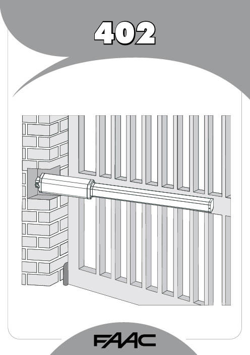
1FAAC S.p.A.Via Benini, 140069 Zola Predosa (BO) - ITALIATel.: 051/61724 - Fax: 051/758518www.faac.it732143 Rev.A.EC DECLARATION OF CONFORMITY FOR MACHINES ....................................................................................p. 2 WARNINGS FOR THE INSTALLER .......................................................................................................................p. 2 1.DESCRIPTION AND TECHNICAL SPECIFICATIONS ....................................................................................p. 31.1.DIMENSIONS ................................................................................................................................p. 32.ELECTRIC DEVICES (standard system) ....................................................................................................p. 33.INSTALLING THE AUTOMATED SYSTEM ......................................................................................................p. 43.1.PRELIMINARY CHECKS ................................................................................................................p. 43.2.INSTALLATION DIMENSIONS ........................................................................................................p. 43.2.1.GENERAL RULES FOR DETERMINING THE INSTALLATION DIMENSIONS ............................p. 43.3.INSTALLATION OF THE OPERATORS .............................................................................................p. 44.START-UP ....................................................................................................................................................p. 64.1.ADJUSTING THE ANTI-CRUSHING SYSTEM ..................................................................................p. 65.FINAL OPERATIONS ...................................................................................................................................p. 76.AUTOMATED SYSTEM TEST .........................................................................................................................p. 77.MANUAL OPERATION ...............................................................................................................................p. 78.RESTORING NORMAL OPERATION MODE ................................................................................................p. 79.MAINTENANCE ..........................................................................................................................................p. 710.REPAIRS .....................................................................................................................................................p. 711.TROUBLE SHOOTING .................................................................................................................................p. 821)ATTENTION! To ensure the safety of people, it is important that you readall the following instructions. Incorrect installation or incorrect use of the product could cause serious harm to people.2)Carefully read the instructions before beginning to install the product.3)Do not leave packing materials (plastic, polystyrene, etc.) within reachof children as such materials are potential sources of danger.4)Store these instructions for future reference.5)This product was designed and built strictly for the use indicated in thisdocumentation. Any other use, not expressly indicated here, could compromise the good condition/operation of the product and/or be a source of danger.6)FAAC declines all liability caused by improper use or use other than thatfor which the automated system was intended.7)Do not install the equipment in an explosive atmosphere: the presenceof inflammable gas or fumes is a serious danger to safety.8)The mechanical parts must conform to the provisions of Standards EN12604 and EN 12605.For non-EU countries, to obtain an adequate level of safety, the Standards mentioned above must be observed, in addition to national legal regulations.9)FAAC is not responsible for failure to observe Good Technique in theconstruction of the closing elements to be motorised, or for any deformation that may occur during use.10)The installation must conform to Standards EN 12453 and EN 12445.For non-EU countries, to obtain an adequate level of safety, the Standards mentioned above must be observed, in addition to national legal regulations.11)Before attempting any job on the system, cut out electrical power .12)The mains power supply of the automated system must be fitted with anall-pole switch with contact opening distance of 3mm or greater. Use of a 6A thermal breaker with all-pole circuit break is recommended.13)Make sure that a differential switch with threshold of 0.03 A is fittedupstream of the system.14)Make sure that the earthing system is perfectly constructed, andconnect metal parts of the means of the closure to it.15)The safety devices (EN 12978 standard) protect any danger areasagainst mechanical movement Risks , such as crushing, dragging,and shearing.16)Use of at least one indicator-light (e.g. FAACLIGHT ) is recommendedfor every system, as well as a warning sign adequately secured to the frame structure, in addition to the devices mentioned at point “15”.17)FAAC declines all liability as concerns safety and efficient operationof the automated system, if system components not produced by FAAC are used.18)For maintenance, strictly use original parts by FAAC.19)Do not in any way modify the components of the automated system.20)The installer shall supply all information concerning manual operationof the system in case of an emergency, and shall hand over to the user the warnings handbook supplied with the product.21)Do not allow children or adults to stay near the product while it isoperating.22)Keep remote controls or other pulse generators away from children,to prevent the automated system from being activated involuntarily.23)Transit through the leaves is allowed only when the gate is fully open.24)The user must not attempt any kind of repair or direct action whateverand contact qualified personnel only.25)Maintenance: check at least every 6 months the efficiency of thesystem, particularly the efficiency of the safety devices (including,where foreseen, the operator thrust force) and of the release devices.26)Anything not expressly specified in these instructions is not permitted.WARNINGS FOR THE INSTALLERGENERAL SAFETY OBLIGATIONSEC DECLARATION OF CONFORMITY FOR MACHINES(DIRECTIVE 98/37/EC)Manufacturer:FAAC S.p.A.Address:Via Benini, 1 - 40069 Zola Predosa BOLOGNA - ITALY Declares that:402 mod. operator,•is built to be integrated into a machine or to be assembled with other machinery to create a machine under the provisions of Directive 98/37/EC;•conforms to the essential safety requirements of the following EEC directives:73/23/EEC and subsequent amendment 93/68/EEC.89/336/EEC and subsequent amendment 92/31/EEC and 93/68/EECand also declares that it is prohibited to put into service the machinery until the machine in which it will be integrated or of which it will become a component has been identified and declared as conforming to the conditions of Directive 98/37/EC.Bologna, 01 January 2005The Managing DirectorA. Bassi3These instructions apply to the following models:402 CBC - 402 SBSThe FAAC 402 automated system for swing leaf gates consists of an enbloc composed of an electric pump and a hydraulic piston which transmits drive to the leaf.The model with a hydraulic locking does not require installation of electric locks, as it guarantees mechanical locking of the leaf when the motor is not operating.The model without a hydraulic locking, requires the installation of electric locks to ensure the leaf is mechanically locked.The 402 automated systems were designed and built to automate swing leaf gates. Do not use for any other purpose.Tab. 1: Technical specifications of “402 Operator”MODEL402 CBC402 SBSPower supply voltage 230 Vac(+6%-10%) 50 (6o) Hz Rod extension speed 1.3 cm/s 1 cm/s Pump flow rate1 l/min 0.75 l/min Traction and thrust force 0-500 daN0-690 daNOperating ambient temperature -40°C - +55°CAbsorbed power 220 W Absorbed current 1 A Motor rotation speed 1400 rpm Motor winding temperature 120°C Weight 6.5 kg Type of oil FAAC HP OILProtection class IP 55Single leaf max length 1,80 m3,00 mUse frequency55 (cycles/hour)4To ensure a correctly operating automated system, the structure of the existing gate or gate to be built must satisfy the following requirements:•Max length of leaves according to the dimensions of Table 1 on page 3.• A strong and rigid leaf structure.•Smooth, uniform leaves movement, without any irregular friction during the entire travel;•Existing hinges in good condition.•Travel limit mechanical stops must be provided.We advise you to carry out the metalwork jobs before installing the automated system.The condition of the structure directly influences the reliability and safety of the automated system.Table A : Recommended dimensions for standard operatorsc = The effective rod stroke is shorter than the maximum stroke, inorder to prevent the rod from reaching its stop point internally, during the opening and closing stages.(*) Rod effective stroke (**) maximum dimension1)Fasten the rear attachment on the pilaster, following the indications in Table A . Modify, if necessary, the length of the supplied attachment.Attention : To avoid compromising good operator functionality, we recommend you to respect the indicated dimensions.• For iron pilasters, accurately weld the rear attachment (ref.ባ, Fig. 6) directly on the pilaster.• For masonry pilasters, select one of the following solutions:A)appropriately lay a walling-in plate and then accurately weld the rear attachment.B)secure, with screws and expansion plugs, the rear attachment plate (ref. a, Fig.6) to the pilaster and then accurately weld the rear attachment to theplate as shown in Fig. 6.If the dimensions indicated in table A or B cannot be executed,the following must be considered in order to determine different measurements:-to obtain 90° opening of the leaf: a + b = c.-to obtain over 90° opening of the leaf: a + b < c.-lower a and b dimensions will result in higher speeds . We advise you to observe the current legal regulations;-limit the difference of the a and b dimensions to within 40 mm :higher differences will considerably vary speed during the opening and closing motion;-for reasons of operator dimensions, the minimum Z dimension is 50 mm (Fig. 4);-if the pilaster dimensions or the position of the hinge (dimension d ) do not make it possible to contain dimension a to the required size, a niche must be made in the pilaster as shown in Opening angle 90°110°a (mm)120100b (mm)120100c(*)(mm)240240d(**)(mm)705056-Lastly, remove the key and restore the power supply to the system.For any repairs, contact FAAC’s authorised Repair Centres.78The following table will help you identify and solve some particular conditions.CONDITIONGate not moving.Gate moving slowly.Gate moving jogwise.The operator is losing oil from the breather screw.The leaves stop at slow-down.Gate speed not constant.A B CD E FSUGGESTION-Check if mains power is supplied.-Make sure that the operator is not unlocked. (chapter 8.).-Check the adjustment of the anti-crushing system (paragraph 4.1).-Check oil level inside the tank. (chapter 9 - Fig. 16).-Check the connection and operation of the thrust capacitor.-Check the efficiency of the electronic control unit.-Check the adjustment of the anti-crushing system (paragraph 4.1).-Make sure that you have removed the breather screw (chapter 5).-Run some complete gate opening and closing cycles, in order to release any air inside the piston.-An initial, minimum oil leak is normal. A larger leak may occur if the operator is not fitted in a perfectly horizontal plane. If the oil leak does not stop soon, weadvise you to visit an authorised repair centre.-Check the adjustment of the anti-crushing system (paragraph 4.1).-Incorrect installation dimensions (paragraph 3.2).Notes919M A I N T E N A N C E R E G I S T E R.o N e t a D b o j f o n o i t p i r c s e D se r u t a n g i S 1_______________________________________________________________________________________________________________________________________na i c i n h c e T re m o t s u C 2_______________________________________________________________________________________________________________________________________na i c i n h c e T re m o t s u C 3_______________________________________________________________________________________________________________________________________na i c i n h c e T re m o t s u C 4_______________________________________________________________________________________________________________________________________na i c i n h c e T re m o t s u C 5_______________________________________________________________________________________________________________________________________na i c i n h c e T re m o t s u C 6_______________________________________________________________________________________________________________________________________na i c i n h c e T re m o t s u C 7_______________________________________________________________________________________________________________________________________na i c i n h c e T re m o t s u C 8_______________________________________________________________________________________________________________________________________na i c i n h c e T re m o t s u C 9_______________________________________________________________________________________________________________________________________na i c i n h c e T re m o t s u C 01_______________________________________________________________________________________________________________________________________na i c i n h c e T re m o t s u C I n s t a l l a t i o n t e c h n i c i a n ________________________________________________C u s t o m e r ___________________________________________________________________T y p e of s y s t e m ________________________________________________________S e r i a l n u m b e r _________________________________________________________I n s t a l l a t i o n d a t e ______________________A c t i v a t i o n ________________________S y s t e m c o n f ig u r a t i o nT R A P L E D O M RE B M U N L A I R E S e r o t a u t t A 402C A A F 1e c i v e d y t e f a S 2e c i v e d y t ef a S 1s l l e c o t o h p f o r i a P 2s l l e c o t o h p f o r i a P 1e c i v e d l o r t n o C 2e c i v e d l o r t n o C lo r t n o c o i d a R pm a l g n i h s a l F ec i v ed re h t O ec i v ed re h t O I n d i c a t i o n of r e s i d u a l r i s k s a n d o f f o r e s e e a b l e i m p r o p e r u s e_________________________________________________________________________________________________________________________________________________________________________________________________________________________________________________________________________________________________________________________________________________________________________________________________________________________________________________________________________________________________________________________________________________________________________________________________________________________________________________________________________________________________________________________________________________________________________________________________________________________________________________________________________________________________________________________________________________________________Read the instructions carefully before using the product and store them for future useIf correctly installed and used, the 402 automated system ensures a high degree of safety.Some simple rules on behaviour can prevent accidental trouble:-Do not pass between the leaves when they are moving. Waitfor the leaves to open fully before passing through them.-Do not, on any account stay in between the leaves.-Do not stand near the automated system, and do not allowchildren, persons or things to do so, especially when it is operating.-Keep remote controls or other pulse generators away fromchildren, to prevent the automated system from being activated involuntarily.-Do not allow children to play with the automated system.-Do not willingly obstruct leaves movement.-Prevent any branches or shrubs from interfering with leavesmovement.-Keep indicator-lights efficient and easy to see.-Do not attempt to activate the leaves by hand unless you havereleased them.-In the event of malfunctions, release the leaves to allow accessand wait for qualified technical personnel to do the necessary work.-When you have set manual operation mode, cut power to thesystem before restoring normal operation.-Do not in any way modify the components of the automatedsystem.-Do not attempt any kind of repair of direct action whateverand contact qualified personnel only.-At least every six months: arrange a check by qualifiedpersonnel of the automated system, safety devices and earth connection.These instructions apply to the following models:402 CBC - 402 SBS.The FAAC 402 automated system for swing leaf gates consists of a hydraulic enbloc composed of an electric pump and a hydraulic piston which transmits drive to the leaf.The models with a hydraulic locking do not require installation of an electric lock, as they guarantee mechanical locking of the leaf when the motor is not operating.The other models, without a hydraulic locking always require one or more electric locks to ensure the leaf is mechanically locked.Leaves of up to 3 mt can be automated depending on the selected model.The functioning of the operators is controlled by an electronic control unit, housed in an enclosure with adequate degree of protection against atmosphere agents.The leaves are normally closed.When the electronic control unit receives an opening command from the radio control or any other pulse generator, it activates the hydraulic appliance which rotates the leaves until they reach the opening position to allow access.If automatic mode was set, the leaves close automatically after selected pause time has elapsed.If the semi-automatic mode was set, a second pulse must be sent to close the leaf again.A stop pulse (if supplied) always stops movement.For details on the behaviour of the automated system in different function logics, consult the installer.Automated systems include safety devices (photocells) that prevent the leaves from moving when there is an obstacle in the area they protect.The 402 automated system is supplied standard with a hydraulic anti-crush protection safety device (BY-PASS) which limits the torque transmitted to the leaves.The warning-light indicates the current leaf movement.If the gate has to be moved manually due to a power cut or fault of the automated system, use the release device as follows:-Insert the triangular key on the release screw located in the lower part of the flange (Fig.1).-Turn the release key anti-clockwise for about two turns.-Open or close the leaf manually.To prevent an involuntary pulse from activating the operator during the manoeuvre, cut power to the system before re-locking the operator.-To re-lock the operator, turn the key clockwise until it stops (Fig.1).-Release the operator from the front and rear attachments.732143 - Rev. A。
【诺瓦科技】智慧城市LED灯杆屏多媒体播放器快速使用指南英文版

Taurus SeriesMultimedia PlayersQuick S tart Guide Document V ersion:V1.3.2Document Number:NS120100369Copyright © 2018 Xi ’an NovaStar Tech Co., Ltd. All Rights Reserved.No part of this document may be copied, reproduced, extracted or transmitted in any form or by any means without the prior written consent of Xi ’an NovaStar Tech Co., Ltd.Trademarkis a trademark of Xi ’an NovaStar Tech Co., Ltd.Statementwww.novastar.techi aurus Series Multimedia Players Quick Start GuideTable of ContentsTable of ContentsTable of Contents ............................................................................................................................ ii 1 Overview .. (1)1.1 Scenario (1)1.2 Procedures .................................................................................................................................................. 1 You are welcome to use the product of Xi ’an NovaStar Tech Co., Ltd. (hereinafter referred to as NovaStar). This document is intended to help you understand and use the product. For accuracy and reliability, NovaStar may make improvements and/or changes to this document at any time and without notice. If you experience any problems in use or have any suggestions, please contact us via contact info given in document. We will do our best to solve any issues, as well as evaluate and implement any suggestions.T2Preparation ....................................................... (2)2.1 Getting and Installing Software (2)2.2 Getting Required Account Information (3)3 Taurus Connections (4)3.1 Connecting via Ethernet Cable (4)3.2 Connecting via Local Area Network (LAN) (4)3.3 Connecting via Wi-Fi (5)3.3.1 Wi-Fi AP Mode ..........................................................................................................................................53.3.2 Wi-Fi Sta Mode (6)3.3.3 Wi-Fi AP+Sta Mode (6)4 Receiving Card Parameter Configuration (8)4.1 Loading Configuration File or Configuring the Parameters Manually Through NovaLCT (8)4.2 Loading the Configuration File Through ViPlex Handy (9)5 Screen Configuration (10)6 General Operations (11)6.1 Taurus Login with ViPlex Handy (Android and iOS) (11)6.2 Taurus Login with ViPlex Express (Windows) (11)7 Caution (13)www.novastar.tech ii1Overview1.1 Scenario 1.2 Procedureswww.novastar.tech2 Preparation2 PreparationThis document introduces a quick way to use Taurus series multimedia players and provides instructions for the first-timer.www.novastar.tech2 Preparation3 Taurus ConnectionsTaurus Series Multimedia PlayersQuick Start Guide3 Taurus Connections 3.1 Connecting via Ethernet Cablewww.novastar.tech 3Taurus Series Multimedia PlayersQuick Start GuideNetwork DiagramConfiguration Users can access the Taurus directly when it is connected via the Ethernet cable.ViPlex Handy:Step 1 Refer to 6.1 Taurus Login with ViPlex Handy (Android and iOS ) to log in to the Taurus.Step 2 Click the screen name to enter the Screen management page.Step 3 Choose Network Settings > W ired Network Setting .Step 4 Turn off DHCP and set static IP address for the Taurus.ViPlex Express:Step 1 Refer to 6.2 Taurus Login with ViPlex Express (Windows ) to log in to the Taurus.Step 2 At the top right, click and select DHCP Service .Taurus Series Multimedia PlayersQuick Start GuideStep 3 Enable DHCP service to automatically assign an IP address to the Taurus.3.2 Connecting via Local Area Network (LAN)Network DiagramUsers can access the Taurus through LAN when it is connected via LAN. www.novastar.techTaurus Series Multimedia PlayersQuick Start Guide 3 Taurus ConnectionsConfigurationNo need for configuration.3.3 Connecting via Wi-FiThe Taurus series products have dual Wi-Fi function which can provide Wi-Fi hotspotas well as serve as Wi-Fi Station at the same time. The Wi-Fi working frequencyrange is 2400 MHz to 2483.5MHz.Users can access the Taurus directly when it is connected via Wi-Fi AP .3.3.1 Wi-Fi AP ModeNetwork DiagramConfigurationNo need for configuration. Please connect the Wi-Fi AP of the Taurus. SSID is “AP +last 8 digits of the SN”, for example, “AP10000033”. The default password is“12345678”.3.3.2 Wi-Fi Sta ModeNetwork DiagramUsers can access Taurus through external router when it is connected via Wi-Fi Sta.ConfigurationStep 1Refer to 6 General Operations to log in to the Taurus. Step 2Turn on Wi-Fi Sta mode. Click the Wi-Fi name of the external router and then enter the password of the Wi-Fi.● ViPlex Handy: Select N etwork Settings > W i-Fi Setting in the S creenmanagement page.●ViPlex Express: Select S creen Control > N etwork configuration .3.3.3 Wi-Fi AP+Sta ModeBy using Wi-Fi AP+Sta connection, users can directly access the Taurus or access the Internet through bridging connection.Network Diagram ConfigurationStep 1 Refer to 6 General Operations to log in to the Taurus.Step 2 Turn on Wi-Fi Sta mode. Click the Wi-Fi name of the external router and then enterthe password of the Wi-Fi.● ViPlex Handy: Select Network Settings > Wi-Fi Setting in the Screen management page.●ViPlex Express: Select Screen Control > Network configuration .Related Information● ●The Taurus can be connected to the Internet through following two ways. The priority order of the two ways is from high to low.Wired network Wi-Fi StaQuick Start GuideReceiving Card Parameter ConfigurationStep 5 ClickStep 6 Confirm whether the local PC has the required receiving card configuration file.www.novastar.tech4 Receiving Card Parameter Configuration● Yes. Please perform Load Configuration File .● No. Please perform Manual Configuration .Loading Configuration File Step 1 Select Load Configuration File . Click Browse to choose a configuration file from the local PC.Step 2 Click Next to load the configuration file.Manual ConfigurationStep 1 Select Configure Screen and click Next . Step 2 Configure receiving card parameters based on actual conditions. Step 3 Click Send to Receiving Card .Step 4 Adjust parameters until the screen displays normally and then click Save . Step 5 (Optional) Click Save System Configuration File to back up the receiving card configuration file to the local PC.4If receiving card parameters are already configured, please skip this chapter and perform the operations in 5 Screen Configuration . Loading Configuration File or Configuring the 4.1 Parameters Manually Through NovaLCTStep 1 Open NovaLCT and choose User > M edia Player Login . The system automatically searches the multimedia players in the same networksegment and then displays them in a specified sorting order. Step 2Click the terminal name in the terminal list. Step 3Click Connect System . Step 4Enter user name and password for logging in the terminal, and click OK . The default user name is “ a dmin ” , and the default password is “ 123456 ”. on the main interface, and the Screen Configuration windowpops up as shown in Figure 4-1 .Figure 4-1 The Screen Configuration windowTaurus Series Multimedia PlayersQuick Start Guide4.2 Loading the Configuration File Through ViPlex HandyStep 1 Save the receiving card configuration file to mobile phone.Step 2 Refer to 6.1 Taurus Login with ViPlex Handy (Android and iOS) to log in to the Taurus.Step 3 Click screen name to enter the Screen management page.Step 4 Select Screen Settings > RV Card Configuration to enter the RV CardConfiguration page.Step 5 Select the receiving card configuration file and click Send.5 Screen Configuration5 Screen ConfigurationStep 1 Refer to 6.1 Taurus Login with ViPlex Handy (Android and iOS) to log in to the Taurus.Step 2 Click screen name to enter the Screen management page.Step 3 Select Screen Configuration to enter the Screen Configuration page.Step 4 Configure screen information based on actual conditions and click OK.www.novastar.tech6 General Operations6 General OperationsTaurus series products feature the Wi-Fi AP function which is taken as the example bythis chapter to introduce T aurus Login methods.6.1 Taurus Login with ViPlex Handy (Android and iOS)Before You Begin●Acquire the SSID and password of Wi-Fi AP of Taurus series products. SSID isdefault to be composed of AP and the last 8 numbers of SN, and thepassword is default as “12345678”.●Acquire the login password of user “admin” of which the default password is“123456”.Operating ProceduresViPlex Handy can connect numerous Taurus series products.Step 1 Connect Wi-Fi AP of the Taurus series products.Step 2 Start ViPlex Handy.System can automatically detect the Taurus series products and refresh Screen list.Users can also slide down Screen list to manually refresh the list.●: denotes that Taurus is online and you can log into it.●: denotes that Taurus is offline and you cannot log into it.●: denotes that Taurus login is successful.Step 3 Click Connect next to the screen name.Step 4 Enter the user name and password and click Login.6.2 Taurus Login with ViPlex Express (Windows)Before You Begin●Acquire the SSID and password of Wi-Fi AP of Taurus series products. SSID is default to be composed of AP and the last 8 numbers of SN, and the password is default as “12345678”.www.novastar.tech6 General Operations●Acquire the login password of user “admin ” of which the default password is “123456”.Operating ProceduresViPlex Express can connect numerous Taurus series products.Step 1 Connect Wi-Fi AP of the Taurus series products. Step 2 Start the ViPlex Express.Step 3 Click Refresh and the screen list will be displayed on the page.● ● ●: denotes that Taurus is online and you can log into it. : denotes that Taurus is offline and you cannot log into it. : denotes that Taurus login is successful.After the Taurus is found by ViPlex Express, the ViPlex express will try to log into to the Taurus with the default account or the account used for last login.Step 4 Taurus login is successful or not.Yes. appears and no further operation is required. No.appears and then perform Step 5 .Step 5Click Connect o n the right of the screen information. Step 6Enter the username and password, and click OK .●www.novastar.tech7 Caution 7 CautionFCC CautionAny changes or modifications not expressly approved by the party responsible forcompliance could void the user's authority to operate the equipment.This device complies with part 15 of the FCC Rules. Operation is subject to thefollowing two conditions: (1) This device may not cause harmful interference, and (2)this device must accept any interference received, including interference that maycause undesired operation.Note: This equipment has been tested and found to comply with the limits for a ClassA digital device, pursuant to part 15 of the FCC Rules. These limits are designed toprovide reasonable protection against harmful interference when the equipment isoperated in a commercial environment. This equipment generates, uses, and canradiate radio frequency energy and, if not installed and used in accordance with theinstruction manual, may cause harmful interference to radio communications.Operation of this equipment in a residential area is likely to cause harmful interferencein which case the user will be required to correct the interference at his own expense.This equipment complies with FCC radiation exposure limits set forth for anuncontrolled environment .This equipment should be installed and operated withminimum distance 20cm between the radiator & your body.This transmitter must not be co-located or operating in conjunction with any otherantenna or transmitter.CE CautionThis equipment should be installed and operated with minimum distance 20cmbetween the radiator & your body.IC WarningRSS-Gen Issue 3 December 2010"&"CNR-Gen 3e éditionDécembre 2010:- English:This device complies with Industry Canada licence-exempt RSS standard(s).Operation is subject to the following two conditions: (1) This device may not causeinterference, and (2) This device must accept any interference, including interferencethat may cause undesired operation of the device.- French:www.novastar.tech7 CautionLe présentappareilestconforme aux CNR d'Industrie Canada applicables auxappareils radio exempts de licence. L'exploitationestautorisée aux deux conditionssuivantes:(1) l'appareil ne doit pas produire de brouillage, et(2) l'utilisateur de l'appareildoit accepter tout brouillageradioélectriquesubi, mêmesi lebrouillageest susceptible d'encompromettre le fonctionnement.Replaceable BatteriesCAUTION: Risk of Explosion if Battery is replaced by an Incorrect Type. Dispose ofUsed Batteries According to the Instructions.Batteries RemplaçablesATTENTION: Risque d'explosion si la Batterie est remplacée par un Type Incorrect.Jeter les Batteries Usées Conformément aux Instructions.。
雷赛BASIC编程手册v2.1
3.2.7 STOP ...............................................................................................................18
3.2.8 AUTO..............................................................................................................18
3.3.1 运算符.............................................................................................................19
3.3.2 ABS.................................................................................................................22
3.2.3 SUB.................................................................................................................17
3.2.4 ON GOSUB ....................................................................................................18
雷赛运动控制器 BASIC 语言编程手册
Version 2.1
张艺兴whatuneed歌词【完整版】

张艺兴what u need歌词【完整版】歌词10月7日,张艺兴于生日当天率先发布新专辑抢听曲《whatUneed》并横扫海外榜单,节奏动感旋律多变的solo 单曲一经发布引爆全球,大批海外迷妹迷弟争先自录观看mV 视频,引发广大粉丝强烈共鸣。
日前,张艺兴工作室发布海外迷妹迷弟“神reaction”混剪合辑,魔性片段走红网络。
逗趣合辑不仅从侧面反映出张艺兴的超高海外人气,也同时激发起国内迷妹迷弟的热情,纷纷表示加入录制reaction 视频大军,期待自己的作品也能被“翻牌”。
《whatUneed》概念海报由张艺兴全程参与设计,以纯黑背景搭配英文字样,字形流畅、简洁明了,紫色设计是张艺兴的最爱,同时也是兴迷应援色。
对于首张solo专辑,张艺兴可谓全程亲力亲为,不仅包揽了词曲、编曲的歌曲创作部分,整张专辑的概念创意、筹备制作、编舞等环节也全程参与,注重细节、倾注心血,以期为一直支持喜爱的粉丝们送上最有诚意的音乐作品。
10月4日深夜,结束日本演唱会行程的张艺兴通过个人社交平台发布一段热舞视频,并配文调侃:“我想睡觉,睡不着”,舞蹈动作力道强劲、干净利落,细心粉丝则发现,这段舞蹈动作跟花絮中的舞蹈动作似有相似之处,猜测舞蹈或许与《whatUneed》有关。
粉丝深夜直呼:“你睡不着,撩的迷妹们也睡不着啊!”据悉,张艺兴抢听曲《whatUneed》的solo舞台确定于10月9日在韩国釜山“亚洲音乐节”首度公开。
张艺兴whatuneed歌词【完整版】演唱者:张艺兴作词:张艺兴/cc作曲:张艺兴/DEVINE-cHANNEL编曲:张艺兴/DEVINE-cHANNELwatchbaby听我的音乐围绕气泡SpecialdaycallmecrazyI'llfindthelove人群中一眼就能看到你紫色照明灯玩命转动方向指向你加速心跳假装无心其实很在意午夜激发危险的迷离深夜的红酒杯没有什么能够比得上你散发的香味一直在寻找oh在寻找的理由让我今晚来Playing我还在那个位置等待你视线爱就是像whisky名叫耐人寻味woowooBaby压制不住好感向你靠近Babyyougotmecrazy justtellmewhatyouwantfromme 游走你的眼嘴唇边和双肩留下我的印鉴你在向我点头我再走向前请不要把我拒绝Babybabybabyyou'remylittlelady Babybabybaby Alwaysgotmewaiting BabybabybabyButI'mlikethelittlefeeling Igoonetwoohonetwostep靠近你身边watchbaby这气氛真的美美想做你专属的Driver听着BabyohIcanmakeit让你今晚坠入我的爱河我无法抗拒你望着我抛媚眼Igonnabababalababa沸点无法再冷却大家说爱情都是毒药我已经喝掉你说你不是我的解药我放你走掉满世界配对都很无聊名单满到爆爱迪生发明灯泡却没想到越亮越无聊woowoobaby压制不住好感向你靠近Babyyougotmecrazy justtellmewhatyouwantfromme 游走你的眼嘴唇边和双肩留下我的印鉴你在向我点头我再走向前请不要把我拒绝yeah就在黑夜空间里你散发迷人气息就在这座城市里让我迷失又给指引你好像不太在意我却不得不想你而你我忽远忽近ohmybaby BabybabybabyBabybabybabyBabybabybaby Talkingaboutyoubaby Igoonetwoohonetwostep靠近你身边woowoobaby压制不住好感向你靠近Babyyougotmecrazyjusttellmewhatyouwantfromme游走你的眼嘴唇边和双肩留下我的印鉴你在向我点头我再走向前请不要把我拒绝yeah张艺兴新曲横扫音乐榜单,海外reaction见证超高人气张艺兴新曲《whatUneed》自全球首发,随即横扫海内外多个音乐榜单,单曲mV在youTube和iTunes上的播放量更是创中国歌手新纪录,海外reaction合辑也反映出张艺兴的超高人气。
Glider Flying Handbook说明书

Glider Flying Handbook2013U.S. Department of TransportationFEDERAL AVIATION ADMINISTRATIONFlight Standards Servicei iPrefaceThe Glider Flying Handbook is designed as a technical manual for applicants who are preparing for glider category rating and for currently certificated glider pilots who wish to improve their knowledge. Certificated flight instructors will find this handbook a valuable training aid, since detailed coverage of aeronautical decision-making, components and systems, aerodynamics, flight instruments, performance limitations, ground operations, flight maneuvers, traffic patterns, emergencies, soaring weather, soaring techniques, and cross-country flight is included. Topics such as radio navigation and communication, use of flight information publications, and regulations are available in other Federal Aviation Administration (FAA) publications.The discussion and explanations reflect the most commonly used practices and principles. Occasionally, the word “must” or similar language is used where the desired action is deemed critical. The use of such language is not intended to add to, interpret, or relieve a duty imposed by Title 14 of the Code of Federal Regulations (14 CFR). Persons working towards a glider rating are advised to review the references from the applicable practical test standards (FAA-G-8082-4, Sport Pilot and Flight Instructor with a Sport Pilot Rating Knowledge Test Guide, FAA-G-8082-5, Commercial Pilot Knowledge Test Guide, and FAA-G-8082-17, Recreational Pilot and Private Pilot Knowledge Test Guide). Resources for study include FAA-H-8083-25, Pilot’s Handbook of Aeronautical Knowledge, FAA-H-8083-2, Risk Management Handbook, and Advisory Circular (AC) 00-6, Aviation Weather For Pilots and Flight Operations Personnel, AC 00-45, Aviation Weather Services, as these documents contain basic material not duplicated herein. All beginning applicants should refer to FAA-H-8083-25, Pilot’s Handbook of Aeronautical Knowledge, for study and basic library reference.It is essential for persons using this handbook to become familiar with and apply the pertinent parts of 14 CFR and the Aeronautical Information Manual (AIM). The AIM is available online at . The current Flight Standards Service airman training and testing material and learning statements for all airman certificates and ratings can be obtained from .This handbook supersedes FAA-H-8083-13, Glider Flying Handbook, dated 2003. Always select the latest edition of any publication and check the website for errata pages and listing of changes to FAA educational publications developed by the FAA’s Airman Testing Standards Branch, AFS-630.This handbook is available for download, in PDF format, from .This handbook is published by the United States Department of Transportation, Federal Aviation Administration, Airman Testing Standards Branch, AFS-630, P.O. Box 25082, Oklahoma City, OK 73125.Comments regarding this publication should be sent, in email form, to the following address:********************************************John M. AllenDirector, Flight Standards Serviceiiii vAcknowledgmentsThe Glider Flying Handbook was produced by the Federal Aviation Administration (FAA) with the assistance of Safety Research Corporation of America (SRCA). The FAA wishes to acknowledge the following contributors: Sue Telford of Telford Fishing & Hunting Services for images used in Chapter 1JerryZieba () for images used in Chapter 2Tim Mara () for images used in Chapters 2 and 12Uli Kremer of Alexander Schleicher GmbH & Co for images used in Chapter 2Richard Lancaster () for images and content used in Chapter 3Dave Nadler of Nadler & Associates for images used in Chapter 6Dave McConeghey for images used in Chapter 6John Brandon (www.raa.asn.au) for images and content used in Chapter 7Patrick Panzera () for images used in Chapter 8Jeff Haby (www.theweatherprediction) for images used in Chapter 8National Soaring Museum () for content used in Chapter 9Bill Elliot () for images used in Chapter 12.Tiffany Fidler for images used in Chapter 12.Additional appreciation is extended to the Soaring Society of America, Inc. (), the Soaring Safety Foundation, and Mr. Brad Temeyer and Mr. Bill Martin from the National Oceanic and Atmospheric Administration (NOAA) for their technical support and input.vv iPreface (iii)Acknowledgments (v)Table of Contents (vii)Chapter 1Gliders and Sailplanes ........................................1-1 Introduction....................................................................1-1 Gliders—The Early Years ..............................................1-2 Glider or Sailplane? .......................................................1-3 Glider Pilot Schools ......................................................1-4 14 CFR Part 141 Pilot Schools ...................................1-5 14 CFR Part 61 Instruction ........................................1-5 Glider Certificate Eligibility Requirements ...................1-5 Common Glider Concepts ..............................................1-6 Terminology...............................................................1-6 Converting Metric Distance to Feet ...........................1-6 Chapter 2Components and Systems .................................2-1 Introduction....................................................................2-1 Glider Design .................................................................2-2 The Fuselage ..................................................................2-4 Wings and Components .............................................2-4 Lift/Drag Devices ...........................................................2-5 Empennage .....................................................................2-6 Towhook Devices .......................................................2-7 Powerplant .....................................................................2-7 Self-Launching Gliders .............................................2-7 Sustainer Engines .......................................................2-8 Landing Gear .................................................................2-8 Wheel Brakes .............................................................2-8 Chapter 3Aerodynamics of Flight .......................................3-1 Introduction....................................................................3-1 Forces of Flight..............................................................3-2 Newton’s Third Law of Motion .................................3-2 Lift ..............................................................................3-2The Effects of Drag on a Glider .....................................3-3 Parasite Drag ..............................................................3-3 Form Drag ...............................................................3-3 Skin Friction Drag ..................................................3-3 Interference Drag ....................................................3-5 Total Drag...................................................................3-6 Wing Planform ...........................................................3-6 Elliptical Wing ........................................................3-6 Rectangular Wing ...................................................3-7 Tapered Wing .........................................................3-7 Swept-Forward Wing ..............................................3-7 Washout ..................................................................3-7 Glide Ratio .................................................................3-8 Aspect Ratio ............................................................3-9 Weight ........................................................................3-9 Thrust .........................................................................3-9 Three Axes of Rotation ..................................................3-9 Stability ........................................................................3-10 Flutter .......................................................................3-11 Lateral Stability ........................................................3-12 Turning Flight ..............................................................3-13 Load Factors .................................................................3-13 Radius of Turn ..........................................................3-14 Turn Coordination ....................................................3-15 Slips ..........................................................................3-15 Forward Slip .........................................................3-16 Sideslip .................................................................3-17 Spins .........................................................................3-17 Ground Effect ...............................................................3-19 Chapter 4Flight Instruments ...............................................4-1 Introduction....................................................................4-1 Pitot-Static Instruments ..................................................4-2 Impact and Static Pressure Lines................................4-2 Airspeed Indicator ......................................................4-2 The Effects of Altitude on the AirspeedIndicator..................................................................4-3 Types of Airspeed ...................................................4-3Table of ContentsviiAirspeed Indicator Markings ......................................4-5 Other Airspeed Limitations ........................................4-6 Altimeter .....................................................................4-6 Principles of Operation ...........................................4-6 Effect of Nonstandard Pressure andTemperature............................................................4-7 Setting the Altimeter (Kollsman Window) .............4-9 Types of Altitude ......................................................4-10 Variometer................................................................4-11 Total Energy System .............................................4-14 Netto .....................................................................4-14 Electronic Flight Computers ....................................4-15 Magnetic Compass .......................................................4-16 Yaw String ................................................................4-16 Inclinometer..............................................................4-16 Gyroscopic Instruments ...............................................4-17 G-Meter ........................................................................4-17 FLARM Collision Avoidance System .........................4-18 Chapter 5Glider Performance .............................................5-1 Introduction....................................................................5-1 Factors Affecting Performance ......................................5-2 High and Low Density Altitude Conditions ...........5-2 Atmospheric Pressure .............................................5-2 Altitude ...................................................................5-3 Temperature............................................................5-3 Wind ...........................................................................5-3 Weight ........................................................................5-5 Rate of Climb .................................................................5-7 Flight Manuals and Placards ..........................................5-8 Placards ......................................................................5-8 Performance Information ...........................................5-8 Glider Polars ...............................................................5-8 Weight and Balance Information .............................5-10 Limitations ...............................................................5-10 Weight and Balance .....................................................5-12 Center of Gravity ......................................................5-12 Problems Associated With CG Forward ofForward Limit .......................................................5-12 Problems Associated With CG Aft of Aft Limit ..5-13 Sample Weight and Balance Problems ....................5-13 Ballast ..........................................................................5-14 Chapter 6Preflight and Ground Operations .......................6-1 Introduction....................................................................6-1 Assembly and Storage Techniques ................................6-2 Trailering....................................................................6-3 Tiedown and Securing ................................................6-4Water Ballast ..............................................................6-4 Ground Handling........................................................6-4 Launch Equipment Inspection ....................................6-5 Glider Preflight Inspection .........................................6-6 Prelaunch Checklist ....................................................6-7 Glider Care .....................................................................6-7 Preventive Maintenance .............................................6-8 Chapter 7Launch and Recovery Procedures and Flight Maneuvers ............................................................7-1 Introduction....................................................................7-1 Aerotow Takeoff Procedures .........................................7-2 Signals ........................................................................7-2 Prelaunch Signals ....................................................7-2 Inflight Signals ........................................................7-3 Takeoff Procedures and Techniques ..........................7-3 Normal Assisted Takeoff............................................7-4 Unassisted Takeoff.....................................................7-5 Crosswind Takeoff .....................................................7-5 Assisted ...................................................................7-5 Unassisted...............................................................7-6 Aerotow Climb-Out ....................................................7-6 Aerotow Release.........................................................7-8 Slack Line ...................................................................7-9 Boxing the Wake ......................................................7-10 Ground Launch Takeoff Procedures ............................7-11 CG Hooks .................................................................7-11 Signals ......................................................................7-11 Prelaunch Signals (Winch/Automobile) ...............7-11 Inflight Signals ......................................................7-12 Tow Speeds ..............................................................7-12 Automobile Launch ..................................................7-14 Crosswind Takeoff and Climb .................................7-14 Normal Into-the-Wind Launch .................................7-15 Climb-Out and Release Procedures ..........................7-16 Self-Launch Takeoff Procedures ..............................7-17 Preparation and Engine Start ....................................7-17 Taxiing .....................................................................7-18 Pretakeoff Check ......................................................7-18 Normal Takeoff ........................................................7-19 Crosswind Takeoff ...................................................7-19 Climb-Out and Shutdown Procedures ......................7-19 Landing .....................................................................7-21 Gliderport/Airport Traffic Patterns and Operations .....7-22 Normal Approach and Landing ................................7-22 Crosswind Landing ..................................................7-25 Slips ..........................................................................7-25 Downwind Landing ..................................................7-27 After Landing and Securing .....................................7-27viiiPerformance Maneuvers ..............................................7-27 Straight Glides ..........................................................7-27 Turns.........................................................................7-28 Roll-In ...................................................................7-29 Roll-Out ................................................................7-30 Steep Turns ...........................................................7-31 Maneuvering at Minimum Controllable Airspeed ...7-31 Stall Recognition and Recovery ...............................7-32 Secondary Stalls ....................................................7-34 Accelerated Stalls .................................................7-34 Crossed-Control Stalls ..........................................7-35 Operating Airspeeds .....................................................7-36 Minimum Sink Airspeed ..........................................7-36 Best Glide Airspeed..................................................7-37 Speed to Fly ..............................................................7-37 Chapter 8Abnormal and Emergency Procedures .............8-1 Introduction....................................................................8-1 Porpoising ......................................................................8-2 Pilot-Induced Oscillations (PIOs) ..............................8-2 PIOs During Launch ...................................................8-2 Factors Influencing PIOs ........................................8-2 Improper Elevator Trim Setting ..............................8-3 Improper Wing Flaps Setting ..................................8-3 Pilot-Induced Roll Oscillations During Launch .........8-3 Pilot-Induced Yaw Oscillations During Launch ........8-4 Gust-Induced Oscillations ..............................................8-5 Vertical Gusts During High-Speed Cruise .................8-5 Pilot-Induced Pitch Oscillations During Landing ......8-6 Glider-Induced Oscillations ...........................................8-6 Pitch Influence of the Glider Towhook Position ........8-6 Self-Launching Glider Oscillations During Powered Flight ...........................................................8-7 Nosewheel Glider Oscillations During Launchesand Landings ..............................................................8-7 Tailwheel/Tailskid Equipped Glider Oscillations During Launches and Landings ..................................8-8 Aerotow Abnormal and Emergency Procedures ............8-8 Abnormal Procedures .................................................8-8 Towing Failures........................................................8-10 Tow Failure With Runway To Land and Stop ......8-11 Tow Failure Without Runway To Land BelowReturning Altitude ................................................8-11 Tow Failure Above Return to Runway Altitude ...8-11 Tow Failure Above 800' AGL ..............................8-12 Tow Failure Above Traffic Pattern Altitude .........8-13 Slack Line .................................................................8-13 Ground Launch Abnormal and Emergency Procedures ....................................................................8-14 Abnormal Procedures ...............................................8-14 Emergency Procedures .............................................8-14 Self-Launch Takeoff Emergency Procedures ..............8-15 Emergency Procedures .............................................8-15 Spiral Dives ..................................................................8-15 Spins .............................................................................8-15 Entry Phase ...............................................................8-17 Incipient Phase .........................................................8-17 Developed Phase ......................................................8-17 Recovery Phase ........................................................8-17 Off-Field Landing Procedures .....................................8-18 Afterlanding Off Field .............................................8-20 Off-Field Landing Without Injury ........................8-20 Off-Field Landing With Injury .............................8-20 System and Equipment Malfunctions ..........................8-20 Flight Instrument Malfunctions ................................8-20 Airspeed Indicator Malfunctions ..........................8-21 Altimeter Malfunctions .........................................8-21 Variometer Malfunctions ......................................8-21 Compass Malfunctions .........................................8-21 Glider Canopy Malfunctions ....................................8-21 Broken Glider Canopy ..........................................8-22 Frosted Glider Canopy ..........................................8-22 Water Ballast Malfunctions ......................................8-22 Retractable Landing Gear Malfunctions ..................8-22 Primary Flight Control Systems ...............................8-22 Elevator Malfunctions ..........................................8-22 Aileron Malfunctions ............................................8-23 Rudder Malfunctions ............................................8-24 Secondary Flight Controls Systems .........................8-24 Elevator Trim Malfunctions .................................8-24 Spoiler/Dive Brake Malfunctions .........................8-24 Miscellaneous Flight System Malfunctions .................8-25 Towhook Malfunctions ............................................8-25 Oxygen System Malfunctions ..................................8-25 Drogue Chute Malfunctions .....................................8-25 Self-Launching Gliders ................................................8-26 Self-Launching/Sustainer Glider Engine Failure During Takeoff or Climb ..........................................8-26 Inability to Restart a Self-Launching/SustainerGlider Engine While Airborne .................................8-27 Self-Launching Glider Propeller Malfunctions ........8-27 Self-Launching Glider Electrical System Malfunctions .............................................................8-27 In-flight Fire .............................................................8-28 Emergency Equipment and Survival Gear ...................8-28 Survival Gear Checklists ..........................................8-28 Food and Water ........................................................8-28ixClothing ....................................................................8-28 Communication ........................................................8-29 Navigation Equipment ..............................................8-29 Medical Equipment ..................................................8-29 Stowage ....................................................................8-30 Parachute ..................................................................8-30 Oxygen System Malfunctions ..................................8-30 Accident Prevention .....................................................8-30 Chapter 9Soaring Weather ..................................................9-1 Introduction....................................................................9-1 The Atmosphere .............................................................9-2 Composition ...............................................................9-2 Properties ....................................................................9-2 Temperature............................................................9-2 Density ....................................................................9-2 Pressure ...................................................................9-2 Standard Atmosphere .................................................9-3 Layers of the Atmosphere ..........................................9-4 Scale of Weather Events ................................................9-4 Thermal Soaring Weather ..............................................9-6 Thermal Shape and Structure .....................................9-6 Atmospheric Stability .................................................9-7 Air Masses Conducive to Thermal Soaring ...................9-9 Cloud Streets ..............................................................9-9 Thermal Waves...........................................................9-9 Thunderstorms..........................................................9-10 Lifted Index ..........................................................9-12 K-Index .................................................................9-12 Weather for Slope Soaring .......................................9-14 Mechanism for Wave Formation ..............................9-16 Lift Due to Convergence ..........................................9-19 Obtaining Weather Information ...................................9-21 Preflight Weather Briefing........................................9-21 Weather-ReIated Information ..................................9-21 Interpreting Weather Charts, Reports, andForecasts ......................................................................9-23 Graphic Weather Charts ...........................................9-23 Winds and Temperatures Aloft Forecast ..............9-23 Composite Moisture Stability Chart .....................9-24 Chapter 10Soaring Techniques ..........................................10-1 Introduction..................................................................10-1 Thermal Soaring ...........................................................10-2 Locating Thermals ....................................................10-2 Cumulus Clouds ...................................................10-2 Other Indicators of Thermals ................................10-3 Wind .....................................................................10-4 The Big Picture .....................................................10-5Entering a Thermal ..............................................10-5 Inside a Thermal.......................................................10-6 Bank Angle ...........................................................10-6 Speed .....................................................................10-6 Centering ...............................................................10-7 Collision Avoidance ................................................10-9 Exiting a Thermal .....................................................10-9 Atypical Thermals ..................................................10-10 Ridge/Slope Soaring ..................................................10-10 Traps ......................................................................10-10 Procedures for Safe Flying .....................................10-12 Bowls and Spurs .....................................................10-13 Slope Lift ................................................................10-13 Obstructions ...........................................................10-14 Tips and Techniques ...............................................10-15 Wave Soaring .............................................................10-16 Preflight Preparation ...............................................10-17 Getting Into the Wave ............................................10-18 Flying in the Wave .................................................10-20 Soaring Convergence Zones ...................................10-23 Combined Sources of Updrafts ..............................10-24 Chapter 11Cross-Country Soaring .....................................11-1 Introduction..................................................................11-1 Flight Preparation and Planning ...................................11-2 Personal and Special Equipment ..................................11-3 Navigation ....................................................................11-5 Using the Plotter .......................................................11-5 A Sample Cross-Country Flight ...............................11-5 Navigation Using GPS .............................................11-8 Cross-Country Techniques ...........................................11-9 Soaring Faster and Farther .........................................11-11 Height Bands ..........................................................11-11 Tips and Techniques ...............................................11-12 Special Situations .......................................................11-14 Course Deviations ..................................................11-14 Lost Procedures ......................................................11-14 Cross-Country Flight in a Self-Launching Glider .....11-15 High-Performance Glider Operations and Considerations ............................................................11-16 Glider Complexity ..................................................11-16 Water Ballast ..........................................................11-17 Cross-Country Flight Using Other Lift Sources ........11-17 Chapter 12Towing ................................................................12-1 Introduction..................................................................12-1 Equipment Inspections and Operational Checks .........12-2 Tow Hook ................................................................12-2 Schweizer Tow Hook ...........................................12-2x。
- 1、下载文档前请自行甄别文档内容的完整性,平台不提供额外的编辑、内容补充、找答案等附加服务。
- 2、"仅部分预览"的文档,不可在线预览部分如存在完整性等问题,可反馈申请退款(可完整预览的文档不适用该条件!)。
- 3、如文档侵犯您的权益,请联系客服反馈,我们会尽快为您处理(人工客服工作时间:9:00-18:30)。
Training Manual启动第章3第3章–启动IN Training Manual进入ANSYS 有两种方式: 交互式和批处理ANSYS 检验每步操作概述NTRODU •交互式方式可以灵活地使用ANSYS,检验每一步操作。
–分析中常用的三个阶段—前处理,求解,后处理—前处理和后处理最适合于交互式方式。
批处理UCTION •方式允许提交批处理文件,ANSYS 在后台运行.•主要讨论交互式方式.N TO AN N SYS 12NSYS 122.02.0IN Training Manual命令启动•在系统平台上通过键入一个命令来启动启动AN SYSNTRODU 在系统平台上通过键入个命令来启动ANSYS.•这里不作讨论,具体可参看操作指南.UCTION 产品启动台•允许选择和启动ANSYS 产品和服务.•在Unix 操作系统下,用launcher120建立启动台.N TO AN •在Windows 操作系统下, 使用:–Start > Programs > ANSYS 12.0 > Mechnical APDL Product Launcher –开始>程序>ANSYS 12.0 > Mechnical APDL Product LauncherNSYS 122.02.0IN Training Manual•启动台主要有三个标签, File Management, Customization /Preferences,及Distrib ted Sol er Set p 产品启动台NTRODU Distributed Solver Setup.•File Management 标签用UCTION g 于指定工作目录(用户文件存放的地方)和用户选择的作业名.N TO AN N SYS 12NSYS 122.02.0IN Training Manual•Customization/Preference … 产品启动台NTRODU 标签允许设置内存选项.•另外,GUI 语言和指定图形驱动设备等选项也在这里设置UCTION .•也可以在启动时读入配置文件start.ans.N TO AN N SYS 12NSYS 122.02.0IN Training Manual•ANSYS 执行内存是指ANSYS 本身所占内存。
时在可执行内存之外另增加的那部内存概述NTRODU •ANSYS 工作空间是指运行ANSYS 时,在可执行内存之外另增加的那部分内存。
•实际内存是指总的物理内存(RAM),即计算机内存芯片的可用内存。
UCTION •系统虚拟内存是指计算机硬盘的一部分,这部分用以作为物理内存的补充。
N TO AN N SYS 12NSYS 122.02.0IN Training Manual•工作空间(如–m )是ANSYS 运行所需的内存空间。
Windows 和UNIX 系512MB 内存NTRODU 统的缺省是512 MB 。
•数据库空间(如–db)用于ANSYS 数据库。
如几何模型,材料属性,荷载等。
对Windows 系统和UNIX 系统缺省为256MB 。
是进行内部计算的空间如单元矩阵的形成波前法求解布UCTION •暂存空间是进行内部计算的空间,如单元矩阵的形成、波前法求解、布尔运算等。
N TO AN N SYS 12NSYS 122.02.0暂存空间=工作空间–数据库第3章–启动IN Training Manual•ANSYS 内存管理器: 产品发射台上Customization/Preferences 标签中的‘Use Custom Memory Settings ’内存管理NTRODU Use Custom Memory Settings 未被选中时使用ANSYS 内存管理器.–指定ANSYS 内存管理器后, 如果必要,ANSYS 将从系统中分配更多的内存.–如果指定的是自定义内存设置,则不能访问更多的内存,并且指定内存不能从别.UCTION 的任务中释放•通常情况下,用户不必担心ANSYS 中的内存管理器. 它将自动完成这些工作. 需要设置整个工作空间时例外.N TO AN •如果需要更多的有关内存管理器和配置的信息,可参看基本分析过程指南第19章.NSYS 122.02.0第3章–启动IN Training Manual 工具条菜单图Contact Manager Icon 布局公用菜单显示/隐藏图标命令窗口图标NTRODU 输出窗口标主菜单输入行Reset pickingUCTION 缩写工具条菜单N TO AN 模型控制工具条绘图区NSYS 122.02.0当前设置用户提示信息第3章–启动IN Training Manual布局•用户可以设置界面布局:NTRODU 移动顶线可以改变工具条的移动左边线可以改变主菜单区域UCTION 尺寸的尺寸N TO AN 点击并拖拉顶、底、左、右边线可以改变图形区域大小NSYS 12通过Utility Menu >MenuCtrls >Save Menu 2.0Utility Menu MenuCtrls Save Menu Layout 可以保存用户对界面布局的设置第3章–启动IN Training Manual•界面布局的系统字体和颜色也可由用户设定:Windows 布局NTRODU –系统:•使用系统显示属性–Unix 系统:UCTION •公共台式环境(CDE)使用系统设置•否则(如:远程登陆到Unix 操作系统)使用~/.X 缺省设置–*EUIDL*字体: 12倍普通字体N TO AN –*EUIDL*背景: 紫色•使用Tcl/Tk 语言,模块化图形用户界面,显示对话框和ANSYS 信息等。
可以很容易将界面转变为母语界面。
NSYS 122.02.0第3章–启动IN Training Manual图形窗口•显示实体模型位置,后处理轮廓和后处理图形。
NTRODU U CTION UCTION N TO AN N TO AN 图形区NSYS 122.02.0第3章–启动IN Training Manual•树形结构。
主菜单NTRODU •包含分析所需的主要功能。
•使用滚动条可以浏览长树形结构。
UCTION N TO AN N TO AN N SYS 12NSYS 12滚动条2.0第3章–启动IN Training Manual•树形结构特性–预置下级分支主菜单NTRODU 关闭前处理分支之前展开前处理分支之后UCTION 选择关闭前处理分支N TO AN NSYS 122.02.0主菜单上前处理分支关闭前后,树形结构的形式完全一样.完样第3章–启动IN Training Manual•展开所有选项主菜单NTRODU 将鼠标停留在主菜单分支处,然后按鼠标右键UCTION N TO AN N TO AN N SYS 12NSYS 12显示展开分支的所有选项2.0选择“Expand All”项展开所有分支内容第3章–启动IN Training Manual在主菜单上按右键,然后选择主菜单NTRODU Preferences 。
UCTION 可以改变主菜单中各级颜色过滤以选项N TO AN ,过滤以及展开选项。
NSYS 122.02.0第3章–启动IN Training Manual用“扩展标题”和“关闭同属”激活…主菜单NTRODU 打开建立体分支UCTION N TO AN N SYS 12NSYS 12当删除分支打开时,建立体分支被关闭2.0注意:没有激活“关闭同属”将保持建立体分支第3章–启动IN Training Manual结构和热单元类型主菜单只有热单元类型主菜单过滤分支NTRODU U CTION UCTION N TO AN N TO AN N SYS 12NSYS 12“Apply” 2.0这里只显示所选单元类型的Apply 分支IN Training Manual•缩写--使用常用命令和功能的捷径。
缩写工具条菜单NTRODU •只有少许预先定义好的缩写可直接使用,但用户可在缩写工具条内添加自己的缩写。
这需要用户了解ANSYS 命令。
•强大的功能允许用户建立自己的“按钮菜单”体系!UCTION N TO AN N TO AN N SYS 12NSYS 122.02.0IN Training Manual•包含常用的工具图标。
用户以设置具图标内容如辅助具条工具栏菜单图标NTRODU •用户可以设置工具图标内容(如:添加项目, 辅助工具条)UCTION 平移-缩放-旋转ANSYS 保存分析捕捉图形N TO AN 打开ANSYS 文件生成报告NSYS 12新分析ANSYS 帮助2.0第3章–启动IN Training Manual•当使用打开ANSYS 文件图标时,工作名会被重定义:作名将被改为恢复的数据文件的文件名数据文件的前缀工具栏菜单图标NTRODU –ANSYS 工作名将被改为恢复的数据文件的文件名(数据文件的前缀)。
UCTION 打开ANSYS 文件N TO AN 打开“file11.db” 数据文件(使用打开ANSYS 文件图标)时,工作名将被改为“file11”.NSYS 122.02.0打开ANSYS 文件图标也可用于打开ANSYS 数据库或ANSYS 命令文件类型IN Training Manual•显现/隐藏图标可用来把任何隐藏在其它窗口之后的ANSYS 对话框(输出窗口除外)显现到最前面。
显现/隐藏图标NTRODU U CTION UCTION 选择显现/隐藏图标N TO AN N SYS 12NSYS 12隐藏的Pan/Zoom/Rotate显的2.0显现的Pan/Zoom/RotateIN Training Manual•允许用户输入命令。
(大多数GUI 功能都能通过输入命令来实现. 如果可以通过输入窗口键入输入窗口NTRODU 用户知道这些命令,可以通过输入窗口键入。
)•命令格式动态显示UCTION N TO AN N TO AN 单击X ,命令窗口将回到输入工具条上.单击命令窗口按钮,输入窗口将被分离出来并且可以NSYS 12口将被分离出来,并且可以在屏幕上移动。
2.0第3章–启动IN Training Manual命令流列表•重复执行命令:输入窗口NTRODU 选择下拉箭头观看已执行命令列表UCTION N TO AN N TO AN 使用滚动条可获取所有已执行命令在列出的已执行命令中双击某个命令可重新执行该命令。
NSYS 122.02.0键盘上下箭头可选择不同的列表命令第3章–启动IN Training Manual•包含ANSYS 运行过程中通常使用的功能,如:图形,在线帮助,选择, 文件公共菜单NTRODU 管理等.•使用公共菜单的约定:--“…”表示产生一个对话框表图拾取UCTION --“+”表示图形拾取--“>”表示将产生下一个子菜单--“”(空缺)表示运行一个ANSYS 命令N TO AN N SYS 12NSYS 122.02.0IN Training Manual当前设置图形用户界面的底部显示当前单元属性设置和当前激活坐标系。