BTP-1000PTII用户手册VER2
袋牌打印机配置手册新北洋btp1000pt②安装使用说明
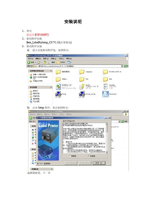
安装说明1、型号新北洋BTP1000PT22、驱动程序名称Beta_LabelPrnSetup_CN V1.33(正常驱动)3、驱动程序安装a) 进入安装驱动程序包,如图所示:b) 点击Setup程序,显示如图所示:选择我接受,下一步标签打印机选择BTP-6200I,点击下一步如图:下一步如图:再点击下一步如图:选择端口号每秒位数选择:19200 其他默认,之后点击安装。
成功提示:c) 安装打印机驱动成功4、配置打印机打开开始菜单,选择打印机和传真。
图1.1打印机和传真5、配置袋牌打印机的纸张右键如图:图1.1打印机和传真空白处。
弹出如图所示:选择创建新格式,填写表格名:BTY-daipai并填写宽度为:5.00高度为:8.10点击确定。
纸张配置完毕。
6、配置打印机的属性右键打印机弹出框,选择属性,如图:点击属性后如图显示:并修改如上图红色部分,修改DPprinter名字。
选择端口选项,如图:端口号选择插入的端口,每秒的位数:19200 其他默认确定。
选择设备设置:选择设置东纸张大小,Envelope-daipai。
7、打印机首选项设置,右键DPprinter,显示如图:选择打印首选项,上述图选择打印选项,图形旋转选择旋转180度打印。
切换到布局,选择高级,弹出如下图:纸张规格选择设计的上述设计的。
北洋打印机调试软件使用1.打开通讯和调试选择端口设置。
点击端口设置,显示如下图:配置串口名称,选择终端的接口,每秒位数为:19200其他默认确定。
2.点击工具选择配置设置,如下图:点击读打印机,在点击读文件。
,选择武汉上海路邮政1000pt2标准配置。
之后点击更新配置。
之后回到主页面点击复位。
重新启动打印机。
打印机安装配置完成。
谢谢观看!。
BTP-1000PTII用户手册VER2

BTP-1000PTII用户手册VER2BTP-1000PTII标签打印机用户手册山东新北洋信息技术股份有限公司声明本手册内容未经同意不得随意更改,山东新北洋信息技术股份有限公司(以下简称新北洋)保留在技术、零部件、软件和硬件上变更产品的权利。
用户如果需要与产品有关的进一步信息,可与新北洋或经销商联系。
未得到新北洋的书面许可,本手册的任何章节不得以任何形式、通过任何手段进行复制或传送。
本手册内容如有任何变动,恕不另行通知。
版权本手册于2007年印制,版权属于新北洋。
中国印制。
2.0版本。
商标新北洋使用的注册商标是警告、注意警告必须遵守,以免伤害人体,损坏设备。
注意给出了打印机操作的重要信息及提示。
新北洋质量管理体系通过下列认证:挪威船级社(DNV)ISO9001:2000 认证本产品已通过下列认证:安全须知在操作使用打印机之前,请仔细阅读下面的注意事项。
➢安全警告警告:打印头为发热部件,打印过程中和打印刚结束不要触摸打印头以及周边部件。
警告:不要触摸打印头表面和连接插件,以免因静电损坏打印头。
➢注意事项1)打印机应安装在一个平整、稳固的地方;2)在打印机的周围留出足够的空间,以便操作和维护;3)打印机应远离水源并避免阳光、强光和热源的直射;4)不要在高温、高湿以及污染严重的地方使用或保存打印机;5)避免将打印机放在有振动或冲击的地方;6)避免打印机表面结露,一旦形成,待露水消失后才可打开电源;7)将打印机的电源适配器连接到一个适当的接地插座上。
避免与大型电机或其它能够导致电源电压波动的设备使用同一插座;8)如果较长时间不使用打印机,请断开打印机电源;9)避免水或导电的物质(例如:金属)进入打印机内部,一旦发生,应立即关闭电源;10)打印机不得在无纸状态下打印,否则将严重损害打印头和胶辊;11)连接/断开各接口时,必须关闭电源,避免打印机控制电路损坏;12)在打印效果满足使用要求的前提下,建议设置尽可能低等级的打印浓度,以提高打印头的使用寿命;13)在压下打印头组件前必须先压下压纸组件,否则不能正常打印;14)用户不得自行拆卸打印机进行检修。
Parker Pneumatic PDN1000-2US 产品说明书
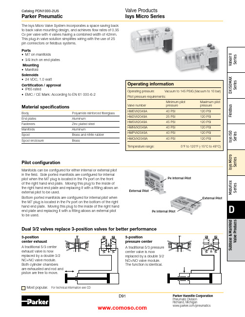
Material specificationsBody Polyamide reinforced fiberglass End plates Aluminum Fasteners Zinc plated steel Manifolds AluminumSpoolBrass and nitrile rubber Spool enclosureBrassMost popular.For technical information see CDThis plug-in valve solution simplifies wiring with the use of 25 pin connectors or fieldbus systems.Ports• M7 on manifolds• 3/8 Inch on end platesMounting • ManifoldSolenoids• 24 VDC, 1.0 wattCertification / approval • IP65 rated• EMC / CE Mark: According to EN 61 000-6-2Manifolds can be configured for either internal or external pilot in the field. Side ported manifolds are configured for internal pilot when the M7 plug is located in the Px port on the front of the right hand end plate. Moving this plug to the inside of the right hand end plate and replacing it with a fitting allows an external pilot to be used.Bottom ported manifolds are configured for internal pilot when the M7 plug is located in the Px port on the bottom of the right hand end plate. Moving this plug to the inside of the right hand end plate and replacing it with a fitting allows an external pilot to be used.External PilotPx Internal PilotPx Internal PilotExternal Pilot3-positioncenter exhaustA traditional 5/3 center exhaust valve is now replaced by a double 3/2 NC+NC valve module. Both cylinder chambers piston are free to move.Dual 3/2 valves replace 3-position valves for better performance3-positionpressure center A traditional 5/3 pressure center valve is nowreplaced by a double 3/2 NO+NO valve module. The function is identical.Pilot configurationPlug-in valve manifolds Part numbers Side port Bottom port Single solenoid outputs onlyPSM21JAPPSM22JAP Double or single solenoid outputsPSM21MAPPSM22MAPIsys Micro ValvesSymbolTypeCv Operator Part numberInternal Pilot End Plate KitsElectrical option Porting Side port Bottom portSimple Manifold Assemblies** Requires fitting “P”.BOLD OPTIONS ARE MOST POPULAR.N 7D 1516Valve Position A - Character 9Fitting Position A - Character 10Valve Position C - Character 13Fitting Position C - Character 14Valve Position B - Character 11Fitting Position B - Character 12Valve Position D - Character 15Fitting Position D - Character 16ACDACDBBIncludes a valve manifold with 4 valves and fittings installed. End Plates must be ordered separately.1. List Add-A-Fold Assembly call out. This automatically includes the end plate kit assembly.2. List Simple Manifold Assemblies. List left to right, LOOkING AT ThE CyLINDER PORTS on the manifold.Maximum Number of Solenoids(Maximum Energized Simultaneously)25-pinD-sub Moduflex Isysnet*Turck16Outputs32Outputs 24VDC24 (24)16 (16)32 (32)16 (16)32 (32) * Maximum of 32 solenoids per manifold. With Bus Extension functionality,4 manifolds with up to 32 solenoids each can be connected on the same network.Add-A-Fold Assembly Model NumberHow To Order Plug-in Add-A-Fold AssembliesNote:BSPP fittings can only be used with BSPP Manifolds.NPT fittings can only be used with NPT Manifolds.Sandwich RegulatorFlow Controls2-position and Dual 3/2 valves, and 0.17 for 3-position APB valves.Note: The sandwich regulator passes full pilot pressure from the manifold,allowing the regulated pressure to adjusted down to 5 PSI without affecting valve functionality.25-pin, D-Sub ManifoldsComponent LevelItem Qty Description Part number 01125-pin, D-sub, end plate PSML25AP0224Single solenoid valveHMEVX2049A 036Manifold, side ported, single address PSM21JAP 04501/4" Tube fittings (in box quantity)PS56792505103/8" Tube fittings (in box quantity)PS5683380613/8" Exhaust muffler P6M-PAB30711/8" Exhaust mufflerP6M-PAB1Add-A-FoldManifold is factory assembled and tested for pneumatic leaks and electrical continuity.Item Qty Description Part number 01124 valve Add-A-Fold with end platesAAHMD5249M0M 0264 valve simple manifold slices #1-6PSM31JAPE7E7E7E725-pin, D-Sub Cable (Female)DescriptionLengthPart number25-pin, D-sub cable, IP20 3 meters P8LMH25M3A 25-pin, D-sub cable, IP209 meters SCD259D 25-pin, D-sub cable, IP65 3 meters SCD253W 25-pin, D-sub cable, IP659 meters SCD259WE24 Single Solenoid ValvesManifold Slice #1Manifold Slice #2Manifold Slice #3Manifold Slice #5Manifold Slice #4Manifold Slice #6MufflersFittings – Must be ordered in multiples of 10ThreadTube O.D.Part numberPSM0001 –All ports open. Common pressure for front and rear mon exhausts.Standard gasket included with each manifold and end plate.Back Row OpenCommon Front Row OpenPSM0001PSM0001PSM0002 –Rear manifold blocked for separate pressure mon exhausts.Flip gasket to block front of manifold.Back Row BlockedCommon Front Row OpenPSM0002PSM0002Intermediate* Qty. (2) PSM0002 Gaskets are required.Remainder are PSM0001 Gaskets (Not shown)Internal Pilot Pressure from P1 InletPSM0003 –Rear manifold blocked for separate pressure supply.Exhaust blocked also.Flip gasket to block front of manifold.If used with bottom ported end plates, second exhaust must be piped from the side of the right end plate.Back Row Blocked Common Front Row OpenIntermediatePSM0003PSM0003PSM0002PSM0002* Qty. (1) PSM0003 and Qty. (1) PSM0002 Gaskets are required.Remainder are PSM0001 Gaskets (Not shown)Internal Pilot Pressure from P1 Inlet PSM0004 –All galleys blocked.Two pressure zones and two exhaust zones.If used with bottom ported end plates, second exhaust must be piped from the side of the right end plate.PressurePressureExhaustExhaustBack Row Blocked Common Front Row BlockedIntermediate * Qty. (1) PSM0004 Gasket is required.Remainder are PSM0001 Gaskets (Not shown)PSM0004PSM0001PSM0004PSM0001Internal Pilot Pressure from P2 InletMultiple Pressure ZonesReplacement ScrewsManifold to Manifold Gaskets*Valve Labels*Replacement Solenoid Kit Replacement Override Caps Replacement Regulator GaugeReplacement Protective CoverReplacement Gaskets and Valve ScrewsReplacement PlugsDescription Part numberDimensionsA 4.88 (124.0)B 4.41 (112.0)C 2.95 (75.0)D 1.65 (42.0)E 1.22 (31.0)F 1.02 (26.0)G 0.71 (18.0)H 0.49 (12.5)J 2.28 (58.0)K 3.44 (87.5)M 0.24 (6.1)N 0.21 (5.2)P 0.41 (10.5)per ManifoldBottom PortedDetail25-pin, D-Sub with Isys Micro Valves, Bottom Ported25-pin, D-Sub with Isys Micro Valves, Side PortedInches (mm)Inches (mm)per ManifoldSide Portedn = Number of manifoldsn = Number of manifoldsDimensionsA 4.88 (124.0)B 4.41 (112.0)C 2.95 (75.0)D 1.65 (42.0)E 1.22 (31.0)F 1.02 (26.0)G 0.71 (18.0)H 0.49 (12.5)J 2.28 (58.0)K 3.44 (87.5)L 1.69 (43.0)M 0.24 (6.1)N 0.21 (5.3)P 0.62 (15.8)Q 1.03 (26.3)R 1.45 (36.8)S 0.64 (16.40)T 1.14 (29.0)U 3.73 (94.9)V 4.23 (107.4)Isysnet with Isys Micro Valves, Bottom PortedDimensionsA 5.67 (144.0)A 14.88 (124.0)B 4.41 (112.0)B 15.24 (133.0)B 24.02 (102.0)C 2.95 (75.0)D 1.65 (42.0)E 0.91 (23.0)G 0.71 (18.0)H 0.49 (12.5)J 2.72 (69.0)K 7.32 (186.0)M 0.24 (6.1)N 2.83 (72.0)Q 1.81 (46.0)R 4.72 (120.0)S 2.01 (51.0)T 2.01 (51.0)DimensionsA 5.67 (144.0)A 14.88 (124.0)B 4.41 (112.0)B 15.24 (133.0)B 24.02 (102.0)C 2.95 (75.0)D 1.65 (42.0)E 0.91 (23.0)G 0.71 (18.0)H 0.49 (12.5)J 2.72 (69.0)K 7.32 (186.0)L 1.69 (43.0)M 0.24 (6.1)N 2.83 (72.0)Q 1.81 (46.0)R 4.72 (120.0)S 2.01 (51.0)T 2.01 (51.0)U 4.41(112)per ManifoldInches (mm)Inches (mm)n = Number of Manifolds m = Number of Modulesn = Number of Manifolds m = Number of ModulesModuflex with Isys Micro Valves, Bottom Ported0.25 (6.4) per Manifold0.25 (6.4) DimensionsA 4.88 (124.0)B 4.41 (112.0)C 2.95 (75.0)D 1.65 (42.0)E 1.22 (31.0)F 1.02 (26.0)G 0.71 (18.0)H 0.49 (12.5)J 2.28 (58.0)K 6.10 (155.0)L 1.69 (43.0)M 0.24 (6.1)N 2.40 (61.0)P 2.36 (60.0)Q 2.07 (52.55)Inches (mm)Inches (mm)n = Number of manifoldsn = Number of manifoldsDimensionsA 4.88 (124.0)B 4.41 (112.0)C 2.95 (75.0)D 1.65 (42.0)E 1.22 (31.0)F 1.28 (32.5)G 0.71 (18.0)H 0.49 (12.5)J 2.28 (58.0)K 6.10 (155.0)M 0.24 (6.1)N 2.40 (61.0)P 2.36 (60.0)Q 2.07 (52.55)Catalog PDN1000-2US Parker PneumaticParker Hannifin Corporation Pneumatic Division Richland, Michigan /pneumaticsD101Valve Products Isys Micro Series Dimensions Turck with Isys Micro Valves, Side PortedDimensions A 7.48 (190)B 5.51 (140)C 5.71 (145)D 0.20 (5)F 1.28 (32.5)G 3.79 (96.5)H 5.06 (128.5)J 2.53 (64.5)K 1.26 (32)L 2.54 (64)M See note 1N 2.28 (58)P 1.65 (42)Q .19 (4.9)R 4.41 (112)S 4.88 (124)Note 1: M =J+L+n 2xk, where n 2 = Number of Turck input / output modules Inches (mm)。
网路通 WN1000RP 2 WiFi 移动设备 WiFi 加速器用户手册说明书

Repetidor WiFi
Aumenta el alcance de la red WiFi existente y crea una señal más fuerte en zonas de difícil acceso.
WiFi existente
En ocasiones el router no proporciona la cobertura WiFi que se necesita.
6
Instale el booster WiFi
Coloque el booster WiFi, enciéndalo y conéctelo a la red WiFi.
Colocación del booster WiFi
1. Coloque el booster WiFi en la misma habitación que el router WiFi.
3
Conozca su booster WiFi
Antes de instalar el booster WiFi, familiarícese con los indicadores y los botones.
Panel frontal y lateral
Indicador de tasa de conexión Indicador LED de estado Indicador de conexión entre el dispositivo WiFi y el booster Botón de encendido/apagado Botón WPS
• Rojo fijo. Mala conexión.
• Apagado. No existe ninguna conexión.
邮政作业系统条码打印设备常见问题解答

1—调节旋钮1 2—透射传感器 3—前逼纸块
4—打印胶辊 5—调节旋钮2 6—定位柱
图5 图6
返回页首
打印机报警“的-的-的-的
四声报警为通讯错误。
1、若先开打印机再开主机,打印机就会报警四声(属于正常报警),可按进纸键排除报警。原因是打印机配置中“串口通信检查”打开。取消串口通讯检查的方法:可通过BARPRNTEST.EXE更改。BARPRNTEST.EXE的使用方法详见BARPRNTEST软件使用说明。
3、检测主机和打印机的串口是否正常。
返回页首
EMS系统下打印机连接不成功如何处理
1、除上述通讯不成功的解决办法外。可在EMS系统“主菜单\7.系统配置与数据维护\1.系统配置\6.外设配置”一项中条码打印机的端口设置为串口1
2、将北洋条码打印机的动态库“EMS V1.33发布”文件夹中的DP.DLL和DP.INI拷贝到c:\emS目录下
打印票面内容浓度过浅或过深,如何处理?
打印票面内容位置偏移如何处理?
打印过程中有一张或几张袋牌,票面深浅不一致时如何处理?
EMS系统下打印机连接不成功如何处理?
EMS系统下打印位置偏移如何处理?
国内EMS系统袋牌打印格式错误如何处理?
国际EMS系统袋牌打印格式错误如何处理?
EMS系统袋牌打印浓度过深如何处理?
具体参数说明请参照国家局项目工程组网站上的《LINUX系统下补充函数说明》
返回页首
主机报打印机初始化不成功
1、检查主机与打印机的连接是否正确(北京昌霖终端为辅口3,其他为辅口1)。
2、检测打印机串口设置是否为19200,N,8,1。可通过BARPRNTEST.exe(笑脸程序)修改打印机波特率。方法是:关闭打印机,按下进纸键开机,等待指示灯连续闪烁三次后松开按键,这时的打印机恢复默认通讯(9600,N,8,1,硬握手,无自动上纸)。用串口,9600初始化打印机。然后,修改打印机串口波特率为19200即可。BARPRNTEST.EXE的使用方法详见BARPRNTEST软件使用说明。
Integrated Heading Sensor PG-1000 产品说明书

INTEGRATED HEADING SENSORPG-10009-52 Ashihara-cho,iSafety Information for the OperatorSafety Information for the InstallerFOREWORDA Word to PG-1000 OwnersCongratulations on your choice of the FURUNO PG-1000 Integrated Heading Sensor. We are confident you will see why the FURUNO name has become synonymous with quality and reliability.For over 50 years Furuno Electric Company has enjoyed an enviable reputation for innovative and dependable marine electronics equipment. This dedication to excellence is furthered by our extensive global network of sales and service.Y our heading sensor is designed and constructed to meet the rigorous demands of the marine environment. However, no machine can perform its intended function unless operated and main-tained properly. Please carefully read and follow the recommended procedures for installation, operation and maintenance.We would appreciate hearing from you about whether we are achieving our purposes. Thank you for choosing FURUNO equipment.Features•The PG-1000 uses a flaxgate magnetic sensor in conjunctions with solid-state angular rate sensor to find heading.•Automatic correction of magnetic variation•Can convert magnetic heading to true heading (requires Furuno GPS Navigator).iiTABLE OF CONTENTSSYSTEM CONFIGURATION (iv)SPECIFICATIONS..........................................................................SP-11 INSTALLATION1.1 Equipment List (1)1.2 Selecting Mounting Location (2)1.3 Mounting (3)1.4 Connections (4)1.5 Correcting Magnetic Field Distortion (Deviation) (5)1.6 Heading Alignment (6)1.7 Setting Output Data (6)2 CORRECTING MAGNETIC ANOMALIES2.1 Controls and Indications (8)2.2 Turning the Power On/Off (8)2.3 Automatic Distortion Compensation (9)2.4 Selecting Output Data Format (9)3 MAINTENANCE & TROUBLESHOTTING3.1 Maintenance (10)3.2 Troubleshooting (10)3.3 Diagnostic Test (11)3.4 Displaying Program Version No (12)PARTS LOCATION AND LIST......................................................AP-1OUTLINE DRAWING.......................................................................D-1SCHMATIC DIAGRAM.....................................................................S-1iiiSYSTEM CONFIGURATIONPG-1000ivSPECIFICATIONS OF INTEGRATED HEADING SENSORPG-1000The PG-1000 is an electromagnetic compass consisting of a fluxgate and a solid-state rate gyro, supported with advanced software. The heading information is outputted in IEC 61162-1 or NMEA format. For high data speed, AD-10 format (25 ms) is also available. The heading information is used for radar, AIS, ECDIS, automatic steering system and other navaids. Heading Accuracy Static ±1.0°, Dynamic ±2.0° at follow-up of 20°/s after correctingdeviationFreedom of tilt ±30°Follow-up 45°/s rate-of turnDisplay resolution 0.1°Useable area 70°N to 70°SCorrection of anomaly Deviation: Automatic correction of coefficients A, B, C, D, E byturning the ship (manual by optional DD-2000 display unit)Variation: Automatic when geographic data is available from a GPSnavigatorI/O Port Input: 1 portOutput: 2 portsInterfacing OutputFURUNO AD-10 format, IEC 61162-1 (NMEA 0183 Ver.2.0)$HCHDG,XXX.X,,,,<CR><LF>$HCHDT,XXX.X,T<CR><LF>For old equipment:$HCHDM,XXX.X,M<CR><LF>$HCHCC,XXX.X,<CR><LF>InputIEC 61162-1 (NMEA 0183 Ver.2.0)$--RMC or $--VTG,either is required for correction of variationData Update AD-10 formatted: 25 msIEC 61162-1 (NMEA 0183): 1 s, 2 s, 100 ms or 200 ms selected Power supply 12-24 VDC: 0.2-0.08 AENVIRONMENTAL CONDITIONTemperature -15°C to +55°C (15°C to 35°C for accuracy ±1.5°)Waterproofing IP5 (IEC 60529), CFR-46 (USCG standard)EMC and others Complies with IEC 60945Coating Housing: Munsell scale N3.0 (Dark gray)Dimensions and mass refer to the Outline DrawingsSP - 11INSTALLATION1.1Equipment ListStandard set.oN emaN e p yT.oNe d oC y tQ s k r ameR 1r o s n e S E-0001-GP----12s l a i r e t aMn o i t a l l a t s n I00020-46PC334-040-0001.wo l e be l b a to t r e f eRInstallation materials (CP64-02000).oN emaN e p yT.oNe d oC y tQ s k r ameR 1we r c sg n i p p a T403SUS61x4080-208-00022r e h s awt a l F403SUS4M621-468-00023e l b a cr ewo P9100S22000-901-00014.y s s ae l b aC001-7000FPS6A-JM732-521-0001Optional units.oN emaN e p yT.oNe d oC y tQ s k r ameR 1e l b a c l a n g i S050-3000FPS6A-JM306-711-0001)01-DAr o f(m5,r o t c e n n o c/w2.y s s ae l b aC001-7000FPS6A-JM732-521-0001)01-DAr o f(m01,p6-p6001-2100FPS6A-JM718-331-0001)AEMNr o f(m01,p6-p61Figure 2 Battery connections to PG-10003.Turn the ship's mains switch on.This sensor doesn't have power switch.About two minutes laterFigure 3 LEDs at power on4.Confirm that the STATUS LED blinks.Two minutes later it will light. If STA TUSLED doesn't blink and then light, suspectsensor error. Reset power.Figure 41.2Selecting MountingLocationThe PG-1000 must be indoor on the horizon-tal plane.When selecting a mounting location, keep inmind the following points:•The ambient temperature must be between-15°C and 55°C.•Vibration at the mounting location shouldbe minimal.•Install the sensor as far as possible frompower cable, ferrous materials.•Install the sensor ship's center of gravity.•Align the bow mark with the ship's bow onthe fore-and-aft-line.1.Tentatively select the mounting location. Donot fix it yet.Ship's bowFigure 1 PG-10002.Connect the PG-1000 to the battery asshown in right.25.Press the [AUTO] and [+] keys togethermore than two seconds.Figure 5 Key and LEDsAfter the TRUE, CALIB and STATUS LEDs light and AUTO LED blinks, rotate the equipment 360º slowly, keeping it uplight. If three LEDs are lighting, themounting location is suitable.Figure 6If one or more LED is off, the mounting location is not suitable. Try to change the location, and do step 5 again.6.Press the [AUTO] and [TRUE] keys to-gether to return to the normal mode. The STA TUS LED blinks while the sensor is be-ing calibrated and lights steady when the calibration is completed. Do not operate the sensor while the LED is blinking; calibra-tion will be incomplete.1.3Mounting1.Fix the sensor by using screws and washers(supplied). The size of the fixing hole is ø4.5 mm.Ship's bowMaterial: Brasso All dimensions in mm.o For added support, use nuts, bolts andwashers.o Secure sufficient clearance around thesensor for maintenance and checking.angles to the fore and aft line.Figure 7 Mounting the PG-1000Note: Do not overtighten the screws or bolts; the sensor may crack.3Checking for inclinationMake sure that the PG-1000 is mounted hori-zontally by the following checks.1.Press the [TRUE] and [+] keys more thantwo seconds.When the inclination is within ±5°, STA TUS LED lights and TRUE LED blinks.Figure 8 LED status wheninclination is within ±5°If STA TUS LED is off, the inclination is over ±5°. In this case, relocate the sensor to where inclination becomes within ±5°or use a levelling brock.2.Press the [AUTO] and [TRUE] keys morethan two seconds to return to the normal mode. The STA TUS LED blinks while the sensor is being calibrated and lights when the calibration is completed (return to nor-mal mode). Do not operate the equipment while the LED is blinking; calibration will be incomplete.1.4ConnectionsConnect cables as shown in the Figure 8. Leave sufficient slack in cables for mainte-nance and checking ease. If cables run outside the bridge run them through conduit to protect them from corrosion.External equipment(Radar, ARPA,Autopilot, etc.) Figure 9 Connections of sensor, top view GroundingGround the PG-1000 as follows to prevent in-terference:•The ground wire should be as short as pos-sible.•The ground wire should be about 1.25 sq and not contain steel.•Use only a closed end lug.Connection of external equipment IEC-61162-1: Digital interface IEC-61162-1 format input/output terminal. Output: HDG, HDT, Input: RMC or VTG.NMEA0183 (Ver.1.5): Outputs HDM (Mag-netic Heading), HCC (Compass Heading). AD-10: Outputs heading information in AD-10 format.Note: Cover unused connector(s) with therubber cap (supplied) to prevent ingress of water.41.5Correcting Magnetic FieldDistortion (Deviation)The magnetic field at the sensor around ship is subjects to change with the ship structure, engins, electronic equipment or any ferrous materials in the vicinity.The PG-1000 contains an automatic correction facility against magnetic field distortion aboard the ship.1.Do this procedure in a calm water.2.Steer the boat clockwise or counterclock-wise in a circular course. Take more than two minutes to complete the circle (at about3 kt). While turning the boat, go to step 3.Figure 10Note 1: Take at least 2 minutes to navigate the circle, otherwise large error may result.Note 2: For hover craft or simular vessel, turn the vessel in a circle maintaining fixed position.3.Press [AUTO] and [TRUE] keys togethermore than two seconds. The CALIB LED blinks.AUTO TRUE CALIB STATUS: Blinking: Off Figure 11 Compensatin falt LED statusduring compensationNote: Y ou can return to normal operation at any time by pressing the [TRUE] key.4.Continue turning the boat in a circle (threeto five times) until a result appears.The correction result is shown with the LEDs. When correction is successful, all LEDs light. Wait 30 seconds for the sensor to return to normal operation, or press the[TRUE] key for quick return.correctionNote 1: Do not turn off the power supply during the correction. Data may be corrupted.Note 2: You may restart correction at anytime during correction or while the correction results are displayed, by pessing [AUTO] key. After pressing the key the AUTO LED lights for two seconds.Note 3: Continue turning the boat even if the CALIB LED status changes from blinking to lighting. Keys are inoperative when the CALIB LED is lighting.Note 4: The sensor does not output heading data during the correction (Program Ver. 3 and after).5.Anchor the boat at the pier to check sensorheading to a known point (for example, lighthouse).If there is a compass error, see "1.6 Head-ing Alignment".If some LED does not light, change sensor location and repeat step 2 through 4.If automatic correction failed at step 4, the correction result is shown in LEDs. This continues until you press any key to clear the display.(Turning off the power at switch board will not clear the LED dis-play.)Note: Bearing output is done with the status before the automatic correction. Failure of automatic correction may be caused by the factors mentioned in the table below. Try the correction again referring to the table.56Figure 13Note: Correction can also be done at Remote Display DD-2000, Multi Display RD-30. See the respective Operator's Manual for details.1.6Heading AlignmentHeading alignment is required when sensor heading is different from actual heading.This alignment must be done using magnetic heading (default setting).Procedure1.Press the [-] and [+] keys together more than two seconds. All LEDs go off.AUTOTRUECALIBSTATUS: OffFigure 14Note: Complete the next step within 10 sec-onds, otherwise normal operation is restored. 2.Set difference between sensor heading (out-put) and actual heading with the [+] or [-]key. For example, the hading output by the sensor is 70° and the actual heading is 75°.Therefore, the difference is +5°. Press the [+] key five times to set +5°. Each time the [+] key is pressed the LEDs light as shown in Figure 14.: OffFigure 15 LED state and pressing of [+] key1.7Setting Output DataSetting output interval The deffault setting is 100 ms.1.Disconnect the power connector from the sensor.2.Reattach the connector to the sensor while pressing the [+] key. The PG-1000 is pow-ered on, and the current output interval is shown by the LEDs.Figure 16 LED state and output interval73.Press the [+] or [-] key to change interval.4.Press the [AUTO] and [TRUE] keys to-gether more than two seconds to return to the normal mode. The STA TUS LED blinks while the equipment is being calibrated and lights when the calibration is completed (re-turn to normal mode). Do not operate the equipment while the LED is blinking; cali-bration will be incomplete.Setting the output sentence(s)Select which type(s) of heading data to output. The default setting is HDG.1.Disconnect the power connector from the sensor.2.Reattach the connector to the sensor while pressing the [-] key. The PG-1000 is pow-ered on, and LED(s) light to show which output sentence(s) is being output.HDG HDT HDM HCCsentenceHDG HDT HDM HCC : Magnetic heading,Magnetic variation value : True heading: Magnetic heading : Compass headingFigure 17 LED and output sentence 3.Press key(s) corresponding to sentence(s)to output. For example, press the [TRUE]key to output HDT.Note 1: Several sentences may be output simultaneously. However, delay may result when the output interval is 100 ms or 200 ms.Note 2: "HDT" outputs true heading data.However, if variation data is not input from the GPS navigator, magnetic bearing will be output.4.Press the [AUTO] and [TRUE] keys to-gether more than two seconds to return to the normal mode. The STA TUS LED blinks while the equipment is being calibrated and lights when the calibration is completed (re-turn to normal mode). Do not operate the equipment while the LED is blinking; cali-bration will be incomplete.2CORRECTING MAGNETIC ANOMALIES2.1Controls and IndicationsTurns on and off deviation corrections.Figure 18 Front panel of PG-10002.2Turning the Power On/Off Note: Y ou may leave port after the STA TUS LED begins lighting (not blinking).Power to the sensor unit may be turned on or off at the mains switchboard.1.Turn the mains switch on.STATUS LED blinks. About two minutes later it lights. Bearing is now reliable.About two minutes later: On: Blinking: Status depends on settings: OffFigure 19 LED state at power on82.3Automatic DistortionCompensationMagnetic field distortion can be automatically corrected as follows:Note: This function is only effective after cor-recting for magnetic field distortion (refer to page 5).1.Press the [AUTO] key more than two sec-onds to light the AUTO LED.Figure 202.To cancel automatic compensation, press the[AUTO] key more than two second to turn off the AUTO LED.Note 1: Turn off this function when your boat is near a steel ship or iron bridge, since they affect sensor performance.Note 2: Correct distortion whenever you feel error is excessive.2.4Selecting Output DataFormatThe PG-1000 can output heading true or mag-netic. The default setting is magnetic heading in AD-10 format.1.Connect Furuno GPS Navigator to PG-1000.RMC or VTG data is required which contains GPS position in RMC, SOG (speed over ground) and COG (course over ground) in VTG.2.Set up magnetic variation (manual or auto-matic) at the GPS navigator.3.Press the [TRUE] key more than two sec-onds.The TRUE LED blinks. It lights when receiving data from the navaid.Figure 21Note: If the TRUE LED dose not light within 90 seconds after pressing the [TRUE] key, check that the GPS navigator is connected and properly working.4.To return to magnetic heading output, pressthe [TRUE] key more than two seconds to turn off the TRUE LED.Note 1: If the PG-1000 stops receiving mag-netic variation data while outputting true head-ing, the TRUE LED stops lighting and blinks. The last used variation data is used.Note 2: Magnetic variation cannot be corrected manually at the PG-1000. Therefore, if you desire true heading output but do not have a navigation aid, you may enter appropriate variation as shown in 1.6 Heading Alignment on page 6.Note 3: HDM and HCC sentence are magnetic heading output sentences. HDG sentence must be changed to true heading at the equipment connected, by using the magnetic heading and magnetic variation data in the sentence.93MAINTENANCE &TROUBLESHOOTING3.1MaintenanceRegular maintenance is important to maintain intended performance over a long period. Regularly check the following:•Clean the component with a soft cloth. Do not use chemical cleaners; they can remove paint and markings.•Make sure all connections are tight.•Check the ground terminal for corrosion. Clean if necessary.3.2TroubleshootingThe table below provides simple troubleshooting procedures which the user can follow to re-store normal operation. If normal operation cannot be restored do not check inside the equip-ment; there are no user-serviceable parts inside. Any repair work should be referred to a qualified technician.mo t pmyS ydemeR.de r ewopebt onna ct i nU.r o t c enno cr ewopk c ehC•.s n i ams'p i h seh tk c ehC•.t hg i l t onodsDEL.r o t c enno cr ewopk c ehC•.t s e tc i t s onga i deh toD•).egapt x eneh to t r e f eR(.r o r r ea t adgn i daeH.t s e t-f l e seh toD•).egapt x eneh to t r e f eR(o t t up t uot ons ia t adgn i daehehT.t nemp i uqel an r e t x e.s no i t c enno ck c ehC•.t s e tc i t s onga i deh toD•).egapt x eneh to t r e f eR(10113.3Diagnostic testThe PG-1000 has a self-test which checks the circuit board and keys for proper operation.LED/KEY/ROM/RAM test1.Disconnect the power cable from the equip-ment.2.While pressing the [AUTO] key, reattach the power cable.The test sequence is as below.: On: Blinking : OffFigure 22 Sequence of LED test 3.Press each key one by one.LED corresponding to the key lights if the key is normal.[AUTO] key: AUTO LED [TRUE] key: TRUE LED [-] key: CALIB LED [+] key: STATUS LED4.Press the [AUTO] and [TRUE] keys to-gether more than two seconds after check-ing all keys. Then, the ROM and RAM are checked.AUTO LED lights: RAM is normal.TRUE LED lights: ROM is normal.5.Press the [AUTO] and [TRUE] keys to-gether more than two seconds to escape from the test. The STA TUS LED blinks while the equipment is being calibrated and lights when the calibration is completed (re-turn to normal mode). Do not operate the sensor while the LED is blinking; calibra-tion will be incomplete.EEPROM/Sensor testThis test checks the EEPROM and sensor. All default settings (navigation setting, output sen-tence, output interval, etc.) are restored at the completion of the test. Do this test after dis-mounting the equipment.1.Disconnect the power cable off from the equipment.2.While pressing the [TRUE] key, reattach the cable. All LEDs go off.3.After AUTO LED lights, turn the equipment through a circle slowly instead of ship's movement until TRUE LED lights. The testproceeds in the sequence shown below.When the equipment finds error, LEDs do not light.: Off (error)Figure 23 EEPROM/Sensortest sequence4.Disconnect the power cable off from theequipment, and then reattach it.5. Mount the equipment at the previous posi-tion, referring to page 3.3.4Displaying ProgramVersion No.When the equipment is powered on, the pro-gram no., denoted by LEDs in binary notation, is shown about 1 second.For example, LED state shown below means the program no. is 5.: On: OffFigure 24 LED state andprogram version no.12PARTS LOCATION AND LISTC PU B o a rdPG-1000, cover openedodC seemk r aRmeNN eaT.oyp141-560P4-41C5Bod r a1U13PAP-1。
【VIP专享】袋牌打印机配置手册:新北洋btp1000pt②安装说明

安装说明1、型号新北洋BTP1000PT22、驱动程序名称Beta_LabelPrnSetup_CN V1.33(正常驱动)3、驱动程序安装a)进入安装驱动程序包,如图所示:b)点击Setup程序,显示如图所示:选择我接受,下一步标签打印机选择BTP-6200I,点击下一步如图:下一步如图:再点击下一步如图:选择端口号每秒位数选择:19200 其他默认,之后点击安装。
成功提示:c)安装打印机驱动成功4、配置打印机打开开始菜单,选择打印机和传真。
图1.1打印机和传真5、配置袋牌打印机的纸张右键如图:图1.1打印机和传真空白处。
弹出如图所示:选择创建新格式,填写表格名:BTY-daipai并填写宽度为:5.00高度为:8.10点击确定。
纸张配置完毕。
6、配置打印机的属性右键打印机弹出框,选择属性,如图:点击属性后如图显示:并修改如上图红色部分,修改DPprinter名字。
选择端口选项,如图:端口号选择插入的端口,每秒的位数:19200 其他默认确定。
选择设备设置:选择设置东纸张大小,Envelope-daipai。
7、打印机首选项设置,右键DPprinter,显示如图:选择打印首选项,上述图选择打印选项,图形旋转选择旋转180度打印。
切换到布局,选择高级,弹出如下图:纸张规格选择设计的上述设计的。
北洋打印机调试软件使用1.打开通讯和调试选择端口设置。
点击端口设置,显示如下图:配置串口名称,选择终端的接口,每秒位数为:19200其他默认确定。
2.点击工具选择配置设置,如下图:点击读打印机,在点击读文件。
,选择武汉上海路邮政1000pt2标准配置。
之后点击更新配置。
之后回到主页面点击复位。
重新启动打印机。
打印机安装配置完成。
谢谢观看!。
BDKQ-1000用户手册

BDKQ-1000 电源快速切换装置用户手册北京北斗银河科技有限公司此文档对应的装置软件版本如下:CPU插件:1.0.5.1COM插件:1.1.5.1.本公司保留对此文档修改的权利,届时恕不另行通知。
产品与说明书不符之处,以实际产品为准。
目录1.概述 (1)1.1.应用范围 (1)1.2.主要功能 (1)1.3.主要特点 (1)2.技术参数 (2)2.1.环境参数 (2)2.2.电源参数 (2)2.3.额定参数 (2)2.4.功率消耗 (2)2.5.精确工作范围 (2)2.6.测量精度 (2)2.7.切换时间 (2)2.8.过载能力 (3)2.9.绝缘 (3)2.10.抗干扰性能 (3)2.11.机械性能 (3)2.12.继电器 (3)2.13.机箱参数及安装方式 (4)2.14.主要硬件参数 (4)2.15.日志参数 (4)3.装置整体介绍 (5)3.1.外形尺寸图 (5)3.2.安装尺寸图 (5)3.3.面板布置图 (6)3.4.背板示意图 (6)3.5.接线原理图 (7)3.6.端子定义 (9)4.装置使用说明 (12)4.1.安装注意事项 (12)4.2.键盘说明 (12)4.3.指示灯说明 (12)4.4.液晶说明 (12)4.5.命令菜单说明 (13)5.工作原理 (15)5.1.插件功能 (15)5.2.原理示意图 (15)6.整定方法 (15)6.1.切换定值 (15)6.2.模入属性 (16)6.3.开入属性 (18)6.4.开出属性 (18)6.5.信灯属性 (18)6.6.功能参数 (18)6.7.闭锁参数 (18)6.8.检修参数 (19)6.9.一次参数 (19)6.10.通讯参数 (20)6.11.管理参数 (20)7.动作逻辑 (21)7.1.起动切换逻辑 (21)7.2.切换逻辑图 (24)7.3.合备用开关逻辑 (24)7.4.其它逻辑 (25)8.调试大纲 (27)8.1.试验注意事项 (27)8.2.交流回路校验 (27)8.3.开入信号校验 (27)8.4.开出信号校验 (27)8.5.开关传动试验 (27)8.6.空载切换试验 (27)8.7.带负荷切换试验 (28)9.运行说明 (29)9.1.正常巡检 (29)9.2.异常信息含义及处理建议 (29)图目录图 1 装置外形尺寸图(单位:mm) (5)图 2 装置开孔尺寸图(单位:mm) (5)图 3 面板布置图 (6)图 4 背板端子示意图 (6)图 5 单母分段方式端子接线示意图 (7)图 6 母方式端子接线示意图 (8)图7 命令菜单结构说明 (13)图8 原理示意图 (15)图9 起动切换逻辑图 (21)图10 起动逻辑1 (21)图11 起动逻辑2 (22)图12 起动逻辑3 (22)图13 起动逻辑4 (22)图14 起动逻辑5 (23)图15 起动逻辑6 (23)图16 切换逻辑图 (24)图17 合备用开关逻辑 (24)图18 防合环逻辑 (25)图19 低压减载逻辑 (25)图20 开关位置异常逻辑 (25)图21 开关假分逻辑 (25)图22 后备失电逻辑 (25)图23 TV断线逻辑 (26)表目录表 1 端子定义 (11)表 2 键盘说明 (12)表 3 指示灯说明 (12)表 4 显示标志说明 (13)表 5 命令菜单功能说明 (14)表 6 插件功能 (15)表7 切换定值 (16)表8 切换控制字.................................................................................................................. 错误!未定义书签。
- 1、下载文档前请自行甄别文档内容的完整性,平台不提供额外的编辑、内容补充、找答案等附加服务。
- 2、"仅部分预览"的文档,不可在线预览部分如存在完整性等问题,可反馈申请退款(可完整预览的文档不适用该条件!)。
- 3、如文档侵犯您的权益,请联系客服反馈,我们会尽快为您处理(人工客服工作时间:9:00-18:30)。
BTP-1000PTII标签打印机用户手册山东新北洋信息技术股份有限公司声明本手册内容未经同意不得随意更改,山东新北洋信息技术股份有限公司(以下简称新北洋)保留在技术、零部件、软件和硬件上变更产品的权利。
用户如果需要与产品有关的进一步信息,可与新北洋或经销商联系。
未得到新北洋的书面许可,本手册的任何章节不得以任何形式、通过任何手段进行复制或传送。
本手册内容如有任何变动,恕不另行通知。
版权本手册于2007年印制,版权属于新北洋。
中国印制。
2.0版本。
商标新北洋使用的注册商标是警告、注意警告必须遵守,以免伤害人体,损坏设备。
注意给出了打印机操作的重要信息及提示。
新北洋质量管理体系通过下列认证:挪威船级社(DNV)ISO9001:2000 认证本产品已通过下列认证:安全须知在操作使用打印机之前,请仔细阅读下面的注意事项。
安全警告警告:打印头为发热部件,打印过程中和打印刚结束不要触摸打印头以及周边部件。
警告:不要触摸打印头表面和连接插件,以免因静电损坏打印头。
注意事项1)打印机应安装在一个平整、稳固的地方;2)在打印机的周围留出足够的空间,以便操作和维护;3)打印机应远离水源并避免阳光、强光和热源的直射;4)不要在高温、高湿以及污染严重的地方使用或保存打印机;5)避免将打印机放在有振动或冲击的地方;6)避免打印机表面结露,一旦形成,待露水消失后才可打开电源;7)将打印机的电源适配器连接到一个适当的接地插座上。
避免与大型电机或其它能够导致电源电压波动的设备使用同一插座;8)如果较长时间不使用打印机,请断开打印机电源;9)避免水或导电的物质(例如:金属)进入打印机内部,一旦发生,应立即关闭电源;10)打印机不得在无纸状态下打印,否则将严重损害打印头和胶辊;11)连接/断开各接口时,必须关闭电源,避免打印机控制电路损坏;12)在打印效果满足使用要求的前提下,建议设置尽可能低等级的打印浓度,以提高打印头的使用寿命;13)在压下打印头组件前必须先压下压纸组件,否则不能正常打印;14)用户不得自行拆卸打印机进行检修。
目录1概述 (1)1.1简介 (1)1.2主要特点 (1)2主要技术指标 (2)2.1主要技术规格 (2)2.2介质技术规格 (2)3外观和组件 (3)3.1外观和组件 (3)3.2主要组件功能介绍 (4)3.3电源、告警指示灯和蜂鸣器 (4)4打印机的安装 (6)4.1打印机开箱 (6)4.2连接AC电源适配器 (6)4.3连接接口电缆 (6)4.4纸卷的安装 (6)4.5碳带的安装 (7)5打印机的启动 (9)5.1打印机开机与自检 (9)5.2打印方式的选择 (9)5.3打印机校验 (9)5.4打印自检样张 (10)5.5打印机常用参数的调整 (10)5.6透射传感器位置调整 (12)6打印机的日常维护 (13)6.1打印头清洁 (13)6.2传感器清洁 (13)6.3打印胶辊清洁 (14)7常见故障处理方法与维护 (15)附录 (16)附录1打印机配置信息 (16)附录2介质的技术规格 (19)附录3接口说明 (21)1概述1.1简介BTP-1000PTII标签打印机采用模块化设计,具有结构简单、操作方便等特点,可广泛适用于交通、邮政、商业物流等领域。
BTP-1000PTII标签打印机可以通过标准并行接口或串行接口与其他设备连接,同时提供WINDOWS95 /98/2000/NT4.0/XP操作系统下的通用驱动程序及基于DLL的软件开发包。
1.2主要特点热敏/热转印打印Easy-Media-Loading结构设计,操作简便、舒适模块化设计,满足不同的应用需求温度自适应控制2主要技术指标2.1主要技术规格2.2介质技术规格本打印机支持连续纸和非连续纸两种纸张类型。
连续纸类型包括:无黏合剂条状卷筒纸非连续纸类型包括:●无黏合剂标记卷筒纸●无黏合剂穿孔卷筒纸各类介质的技术规格详见附录2。
3外观和组件3.1外观和组件图3.1.1 图3.1.21—电源开关2—电源插孔3—标准并口插座4—9针RS-232串行接口插座5—按键6—电源(告警)指示灯7—出纸通道8—打印机上盖9—碳带压力调整旋钮10—碳带发放轴11—碳带回收轴图3.1.3 图3.1.412—碳带传感器13—打印头组件14—左侧逼纸块15—右侧逼纸块16—打印头组件扳手17—压纸组件扳手18—压纸组件19—纸卷支撑架组件20—打印头微动开关21—前逼纸块22—透射传感器23—定位柱224—定位柱1 25—调节旋钮26—打印胶辊3.2主要组件功能介绍A----电源开关(1)按下“O”关闭电源,按下“|”开启电源;B----按键(5)进纸按键功能●按住进纸按键并打开电源开关,与电源指示灯配合功能如下表:●其它状态下进纸按键功能✧打印机待机状态下按此键:打印机前进一个票面;✧打印机出错状态下按此键:排除打印机错误,恢复打印机到待机状态;✧撕离模式打印时电源指示灯将闪烁,等待用户按下进纸按键确认打印此票面,此时按此键,打印机将退纸到打印头下并开始打印。
暂停按键功能打印过程中按下此键,打印机进入暂停状态,此时可以抬起打印头,调整介质位置或更换介质,按下并锁紧打印头,再按下暂停按键,打印机继续打印。
C----电源(告警)指示灯(6)检测电源的开关状态和反映打印机是否处于正常的状态;D----碳带传感器(12)探测打印机碳带的存在状态;E----逼纸块(14,15,21)将介质夹在逼纸块之间,防止介质在通道中左右滑动,否则打印机将无法正常判别介质状态;F----压纸组件(18)减轻介质在出纸通道中上下波动,以免造成打印机定位不准确。
G----打印头微动开关(20):检测打印头位置(抬起/压下)状态;H----纸标记传感器包括透射传感器(22)和反射传感器,反射传感器位于前逼纸块(21)下面,距通道左边缘5mm,用于检测介质的存在状态及标记。
3.3电源、告警指示灯和蜂鸣器3.3.1电源和告警指示灯状态功能表3.3.2告警指示灯和蜂鸣器状态功能1)蜂鸣器短鸣:打印机在开机或复位正确时,蜂鸣器短鸣一声;2)4打印机的安装4.1打印机开箱打开打印机包装,对照装箱单检查物品是否缺少或损坏。
如果出现物品缺少或损坏现象,请立即与经销商联系。
4.2连接AC电源适配器1)确认打印机的电源开关处于关闭状态;2)将电源适配器电缆插头平直的一面向上,插入打印机侧面的电源接口内;3)接通电源适配器的输入电源。
注意:⏹应采用厂家推荐的电源适配器或等同产品;⏹插拔电源适配器插头时,应手持插头的连接器外壳,不要用力拉拔电缆;⏹避免拖动电源适配器的电缆,否则会损坏电缆,引起火灾和电击;⏹避免将电源适配器放置在过热的设备周围,防止电缆表面融化,引起火灾和电击;⏹如果较长时间不使用打印机,请断开打印机电源适配器的电源。
4.3连接接口电缆1)确认打印机的电源开关处于关闭状态;2)将接口电缆插入相配的接口内,并用插头的螺丝钉或卡簧固定;3)将接口电缆的另一端连接到主机上。
注意:请勿带电插拔接口电缆!4.4纸卷的安装4.4.1打印介质类型的确认介质安装前首先应确认打印机使用的纸张类型。
默认的纸张类型为袋牌纸,如果采用其它类型的打印纸张,应首先通过指令集中的命令设置相应纸张类型。
设置方法参见《条码打印机编程手册》。
4.4.2安装打印纸卷1)打开打印机的上盖;2)如图4.1所示,依次抬起打印头组件、压纸组件;3)如图4.2所示,将纸卷装在支撑杆上,两侧安装逼纸板,然后装在支撑架中;4)按图4.3所示,将纸张夹在两个逼纸块之间,调整逼纸块,使其距纸张的间隙不超过1mm;图4.1 图4.2 图4.3 图4.45) 将纸前端放在打印胶辊上;6) 如图4.4所示,确认纸正确地安装在通道内后,依次压下压纸组件、打印头组件; 7) 合上打印机上盖。
注意:⏹ 纸的打印面应朝上,若为黑标记纸,请将黑标记朝下;⏹ 打印头组件及压纸组件必须锁紧可靠,否则会影响打印机的正常工作; ⏹ 装纸前,应确认纸张符合下图正确的要求:4.4.3 清除塞纸依次打开打印机上盖、打印头组件、压纸组件,沿走纸通道清除塞纸。
4.5 碳带的安装1) 按如图4.5所示,确定碳带内、外置方式后,将碳带装入碳带发放芯轴上;图4.52) 按图4.6所示将碳带发放轴与碳带压力调整旋钮内侧的前端配合在一起;图4.6外置碳带的安装 内置碳带的安装3)压下碳带发放轴的另一侧,使其卡入右侧锁紧槽内;4)将空的碳带芯轴装到碳带回收轴上,并装配到相应的位置;5)如图4.7所示抬起打印头组件,将碳带从打印头组件下面绕过并拉向碳带回收轴;6)按图4.8所示将碳带头用胶带粘贴在碳带芯轴上,并旋转压力调整旋钮使其缠绕数圈;图4.7 图4.87)旋转碳带压力调整旋钮,将碳带呈平整的绷紧状态。
注意:⏹确定打印方式:选择热转印方式,需要安装碳带;选择热敏方式,不需要安装碳带;⏹正常情况下,选用碳带应宽于打印介质的宽度;⏹安装碳带过程中应防止碳带起皱或破损。
5打印机的启动5.1打印机开机与自检1)确认电源线和通讯线已正确连接,打开打印机电源开关;2)打印机自检(初始化),初始化完毕后,蜂鸣器鸣叫一声;3)当蜂鸣器鸣叫一声后,打印机自检结束;非连续型介质且打印机允许自动上纸,打印机会自动上纸到打印位置。
注意:若打印机不能启动或启动后不能正常工作,请及时与经销商联系。
5.2打印方式的选择用户可根据介质的类型,确认打印方式和纸标记传感器类型。
打印机默认的打印方式是热转印方式;默认的纸标记传感器类型是透射传感器。
打印方式的设置方法参见《条码打印机编程手册》。
注意:应根据不同的纸张类型选择正确的打印方式。
5.3打印机校验手动校验功能1)关闭打印机;2)将介质安装好;3)按住进纸键不放,将电源开关扳至“|”位置,当电源指示灯连续闪烁两次后,松开进纸键,打印机进纸并校验标记;4)如果在校验后,打印机报警,说明校验失败,请查找:●介质安装是否正确;●安装介质类型与打印机设置介质类型是否一致。
5)如介质为标记纸,打印机校验内容为标记及票面高度;如介质为无标记纸,打印机校验内容为有无纸状态。
注意:如属以下任何一种情况,打印前需要对介质进行标记校验:⏹第一次安装使用打印机;⏹打印机长时间未使用后重新使用;⏹更换新类型的纸卷;⏹传感器清洁后第一次使用;⏹打印过程中不能有效识别标记;⏹打印机使用环境有较大改变。
自动校验功能在更换不同类型的纸张后,第一次打印时自动启动:1)将介质安装好;2)根据纸张类型正确设置打印机驱动中纸张类型属性及设置正确的页面高度;3) 发送打印命令,打印机将走2~3个票面校验新类型的纸张,成功后进入暂停状态,抬起打印头,卷起校验的票面,将纸头放在打印胶辊上,按下打印头,用户通过按暂停键确认,打印机退出暂停状态并打印;4) 如果校验失败,打印机将报警:● 请确认安装的纸张和打印机驱动属性中所选择的纸张类型是否相同,如果不相同请更改正确后,重新打印,打印机将重新启动自动校验;● 如果设置正确仍然校验失败,请参照手动校验完成纸张校验。