sla7042m
沃茨 M 系列反渗透处理器带内置预处理和膜冲洗 适用型号:M-450 M-1000 M-2400 M

M Series Reverse Osmosis ProcessorWith Built-in Pre-treatment and Membrane FlushFor Models:M- 450M-1000M-2400M-4800M-9600Installation, Operation&Maintenance ManualBefore installing and/or operating Watts M-Series Reverse Osmosis system, read this manual completely. Keep this manual available for future reference. Further information is available by contacting your local Watts distributor. Phone: (623)505-1511Pressure TankAtmospheric TankTABLE OF CONTENTSSpecifications Specifications Chart (4)InstallationMembrane installation (5)Inlet Connection (6)Permeate Line Connection (7)Pressure Tank Connection (8)Atmospheric Storage Tank (9)Plumb to Drain (10)OperationStart Up (11)Alarms (12)MaintenanceQuarterly Maintenance (13)Annual Maintenance (14)WarrantyWarranty (15)Glossary of Terms (17)Specifications Complete System PackagesSPECIFICATIONS M-450 M-1000 M-2400 M-4800 M-9600 DRY WEIGHT lbs. 300 310 350 650 750 WET WEIGHT lbs 550 1700 1750 4000 4100 FEED WATERCOLD/Temp ½”/35°-70° ½”/35°-70° ½”/35°-70° ¾”/35°-70° ¾”/35°-70° HOT/ Temp ½”/70°-140° ½”/70°-140° ½”/70°-140° ¾”/70°-140° ¾”/70°-140° FLOW RATE 2 GPM 4 GPM 8 GPM 12 GPM 24 GPM MAX.HARDNESS 17 Grains 17 Grains 17 Grains 17 Grains 17 Grains MAX. TDS 2500 PPM 2500 PPM 2500 PPM 2500 PPM 2500 PPM MAX. IRON 0.1 MGL 0.1 MGL 0.1 MGL 0.1 MGL 0.1 MGL MAX. PSIG 80 80 80 80 80 MIM. PSIG 25 25 25 25 25 DRAINCONNECTIONFLOOR SINK MIM.w/in 10 ft ofprocessor1/ ¼” 1/ ¼” 1/ ¼” 1/ ¼” 1/ ¼”ELECTRICALREQUIRMENTS VOLTS/AMPS VOLTS/AMPS VOLTS/AMPS VOLTS/AMPS VOLTS/AMPSRO PROCESSOR OPTIONAL 220V 115/7.2 115/7.2 115/11.0220/8.8115/23220/11.5220/11.5DELIVERY PUMP N/A 115/8.8 115/12.4 115/12.4 115/12.4 KDF FILTER N/A N/A N/A 115/2 115/2Membrane InstallationMembraneROFEED WATER MIN/MAX PSIGPIPE SIZE FLOW RATE M-450 25/80 psig ½” 2 GPM M-100 25/80 psig ½” 4 GPM M-240025/80 psig ½” 8 GPMM-4800 25/80 psig 1” 12 GPM M-960025/80 psig 1 ¼”24 GPMInlet ConnectionRequired fittings for Bulkhead & Tank M450 ½” MPT x 3/8C . M1000 ½” MPT x 3/8C M2400 ½” MPT x ½”CM4800 ¾” MPT x ¾” Female Slip Schedule 40 PVC M9600 1” MPT x 1” Female Slip Schedule 40 PVCBall Valve used with Pressure Tank applications.Note: Fittings are included with systems ordered as complete packages only!Permeate Line ConnectionM-450 – M2400½” Tubing or PVC pipe M4800 – M9600 ¾” PVC Schedule 40 pipePressure Tank ConnectionRecommended tubing sizeFrom bulkhead on unit to tank .Note: Fittings are included with Systems ordered as complete packages only!Note: Copper pipe is UNSUITABLE for any plumbing from RO Storage Tank!Recommended materials include: Braided Stainless Steel Tubing, Hard Stainless. Schedule 80 PVC or Poly Propylene is acceptable, if not being connected to boiler or heating system.M-4503/8” M-1000 3/8” M-2400 3/8”M-4800 ¾” M-9600¾”Atmospheric Storage TankBulkhead & Fitting SystemsNote: Copper pipe is UNSUITABLE for any plumbing from RO Storage tank! Recommended materials include: Braided Stainless Steel Tubing, Hard Stainless. Schedule 80 PVC or Poly Propylene, if not being connected to boiler or heating system.M-450 3/8” M-1000 3/8” M-2400 3/8” M-4800 3/4 “ M-96003/4”If the M-Series was ordered with the atmospheric storage tank, the three tank float switches have been installed at the factory. Check to insure the tank floats have not been damaged. 1. Connect the gray electrical cable containing four (4) wires from the M-Series control box to the corresponding electrical connection on the atmospheric tank.Plumb to DrainM-450M-1000M-2400M-4800M-9600Bulkhead Connection 1/2” Poly1/2” Poly1/2” Poly½” PVC¾” PVCDrain Size Min.1 ¼” 1 ¼” 1 ¼’ 1 ¼’ 1 ¼”Start Upü Ensure power switch (located on top of control Box). (#1) is in the OFF position.ü Plug the unit into an appropriate power supply.ü If installing a pressure Tank system, open the BallValve (#2) on the Bulkhead.ü Turn the Blending Valve to coldest setting [90°]. (#3) ü Fully open the Concentrate Needle (#4) Valve by turning it counter clockwise.ü Fully close Recirculate Needle Valve (#5) by turning it clockwise.ü Turn the incoming water supply on the RO processor to the “ON” position.ü Turn the Power Switch (#1) to “ON” position. • The Water inlet solenoid valve will open.• There will be a 5 second delay before the pump starts.• The system may cycle on and off automatically during initial start up as air is purged from system.• Allow the unit to run for 5 minutes while excess air is being purged from system.ü Close the Concentrate Needle Valve (#4) until the Feed Pressure Gauge(#6) reaches a max. of 150 psig. ü Open the Recirculation Needle Valve (#5) until the unit Feed Pressure Gauge (#6) drops to 140 psig.ü Close the Concentrate Needle Valve (#4) until 150 psig is again achieved on the Pump Feed Pressure Gauge (#6).Repeat underlined sequence until both flow meters read equal flows and feed pressure gauge reads 150 psi. At this point the RO processor is operating at its maximum efficiency potential.If using a Pressure Tank, system will continue to operate until Tank Pressure Gauge reads 60 psig or Float Tank, upper float switch is triggered by the water level.674105ALARMSM-Series processors are equipped with audible alarms.1. The Constant Tone signals lack of incoming water pressure.(-------------------------------------------------------- Constant Tone)•Check incoming feed pressure to ensure a minimum of 20 psi.•Water pressure below 20 psi will trigger alarm. Incoming feed waterpressure must be raised.2. One second intermittent beeping signals systems is in Auto –Bypass.(-- -- -- -- -- -- -- -- -- -- -- -- -- -- One second intermittent tone).•During initial start up with empty tank, the system will automatically be inAuto-Bypass until the tank has completely filled. The Auto by pass will only betriggered if the tank pressure drops below 5 psi (Pressure tank systems). Floatswitch controlled Atmospheric tank systems with float switches, remain on untiltank is full and processor has turned off automatically.3. Two second intermittent beeping indicates possible wiring problem orproblem with installation of Float Switches.(---- ---- ---- ---- ---- ---- Two second intermittent tone.)Solution:•Check to ensure labeledelectrical cables are connectedto corresponding floatswitches.•Check conductivity of wire toensure no broken wire cablesexist.•Verify Float position perdrawing to the right.MaintenanceQuarterly Preventive Maintenance for Systems with complete Pre and Post treatment.The M-Series RO processor requires quarterly preventive maintenanceconsisting of replacing (3) pre-filters and postFilters if supplied.1. Pre-filters are located on left side of ROprocessor.5. Unplug unit from Power Supply.6. Place bucket under pre-filters to catch the waterfrom the filter housings.7. Using supplied filter wrench, loosen filter housingstarting on the left.8. Replace with new 5 micron Sediment Filter and replace filterhousing using wrench to tighten securely.(O-rings and Bowls need to be lubricated with a watersoluble lubricant such as KY Jelly).9. Follow the above sequence with remaining filters.and Post Filters if supplied.10. Replace Calcite Feeder located on right hand side of unit usingsupplied filter housing wrench.(Calcite feeder is only needed on units feeding boilers).Follow “START UP” procedures on page 11Annual Preventive MaintenanceNote: If using pliers to remove NEW membrane for any reason, protect end of membrane with cloth, to prevent teeth marks which could result in leaks.Annual Preventive MaintenanceWARRANTYWHAT YOUR WARRANTY COVERS:If any part of your Premier Water Treatment Device is defective in workmanship (excluding replacement filter elements), return the unit within 1 year of date of original purchase. PREMIER will repair or, at PREMIER’S option, replace it at no charge.HOW TO OBTAIN WARRANTY SERVICE:Contact WATTS PREMIER’S customer service department (1-800-752-5582) to obtain a Return Goods Authorization Number (RGA#). Model and Serial Number are required for obtaining an RGA #. For warranty service, ship your water treatment device wit h the RGA # printed on the Shipping Label to PREMIER, freight and insurance prepaid, with proof of original purchase date. PREMIER will repair or replace the water treatment device and ship it back to you prepaid.WHAT YOUR WARRANTY DOES NOT COVER:This warranty does not cover defects resulting from improper installation, customer abuse, misuse, misapplication, improper maintenance, neglect, alteration, accidents, casualties, fire, flood, freezing, heat, environmental factors or acts of nature.This warranty will be voided if defects occur due to failure to observe the following conditions:1. The water treatment device must be hooked up to a potable municipal water supply.2. The pH of incoming water must not be lower than 6.0 or higher than 8.5.3. The incoming water pressure must be between 25 psi and 80 psi. If water pressure exceeds 80 psi a pressure regulator must be installed.4. Incoming water temperature cannot exceed 100° F (40° C).This warranty does not cover any equipment that has been relocated from the site of its original installation.This warranty does not cover equipment that is installed outside North America.LIMITATIONS AND EXCLUSIONS:PREMIER WILL NOT BE RESPONSIBLE FOR ANY IMPLIED WARRANTIES, INCLUDING THOSE OF MERCHANTABILITY AND FITNESS FOR A PARTICULAR PURPOSE.PREMIER WILL NOT BE RESPONSIBLE FOR ANY INCIDENTAL OR CONSEQUENTIAL DAMAGES, INCLUDING TRAVEL EXPENSES, TELEPHONE CHARGES, LOSS OF REVENUE, LOSS OF TIME, INCONVENIENCE, LOSS OF USE OF THE EQUIPMENT, AND DAMAGES CAUSED BY THE EQUIPMENT AND ITS FAILURE TO FUCTION PROPERLY.THIS WARRANTY SETS FORTH ALL OF PREMIER’S RESPONSIBILITIES REGARDING THIS EQUIPMENT.OTHER CONDITIONS: IF PREMIER chooses to replace the equipment, PREMIER may replace it with reconditi o ned equipment. Parts used in repairing or replacing the equipment will be warranted for 90 days from the date the equipment is returned to you or for the remainder of the original warranty period, whichever is longer. This warranty is not assignable or transferable.YOUR RIGHTS UNDER STATE LAW:Some states do not allow limitations on how long an implied warranty lasts and some states do not allow the exclusion or limitation of incidental or consequential damages, so the above limitations or exclusions may not apply to you. This warranty gives you specific legal rights. You may have other legal rights, which vary from state to state.GLOSSARY OF TERMSAtmospheric tank: A storage container requiring additional delivery system to distribute stored water.Typically constructed of polyurethane or stainless steel. Used in situations where greater storagecapacity is needed than offered by conventional pressure tanks.Auto By-Pass: A feature that allows tap water to be delivered to downstream demands in the event the RO processor is unable to meet demand.Brine Seal: A black “O-ring type seal located on one end of membrane that seals the membrane to the vessel preventing cross contamination of process water and feed-water.Calcite Feeder: Calcite is a naturally occurring mineral used to raise the Total Dissolved Solids (TDS) in the water to promote conductivity in the final product water. Used in situations where conductivity isneeded for proper equipment function i.e. conductivity probes.Carbon Block: Acid washed carbon is used to absorb VOC’s (Volatile Organic Chemicals) such as herbicides, pesticides and chlorine, which will damage RO membranes.Concentrate needle valve: A needle valve located on the right side flow meter that controls the concentrate (drain water) water flow to the drain.Concentrate: Water being rinsed to drain after it has been rejected by the membrane.Concentrate Line: Tubing or pipe used to transport concentrated waste water to a suitable drain.Feed pressure: Referring to the water pressure being supplied to the RO processor before it has entered the pre-filter. Raw water.Feed pressure gauge: The upper most gauge on the control panel that indicates the water pressure the membrane is receiving.Flow meter: A meter that reads water flow in gallons/liters per minuteGPM: Gallons per minuteGPD: Gallons per dayHardness: Total quantity of CaCO3 (Calcium/magnesium) present in water.1 gr. = 17.1 TDS in ppm per U.S. gallonIron: A naturally occurring mineral that has detrimental effects on a membranes ability to produce water.Reduced by ion exchange (water softening) or KDF media.KDF Media Filter: A proprietary blend of metals and other substances that help reduce Iron and CaC03 (hardness). Used as pretreatment on some models of high production RO systems.L Copper pipe: A high grade of copper pipe that will withstand water temperatures up to 160 degrees Fahrenheit.Membrane: A thin sheet or surface film, either natural or man-made, of microporus structure that performs as an efficient filter of particles down to the size rang of chemical molecules and ions. Such membranes are termed “semi-permeable” because some substances will pass through but others will not. Usually small ions, water, solvents, gases, and other very small molecules can pass through a membrane, but other ions and macromolecules such as proteins and colloids are barred form passage. Membranes are used in reverse osmosis.GLOSSARY OF TERMS (Continued)Permeate: That portion of the feed water which passes through the membrane to become product water. Permeate Line: Tubing or pipe used to transport purified (RO processed) water from processor to the storage tank.Pressure tank: A water storage device using a pressurized bladder that provides delivery pressure to down stream uses.Purge: The act of flushing out. A term to describe the purging of entrained air in a systemRecirculation Valve: A needle control valve used to blend concentrate water past the membrane again to scavenge water molecules.Recirculation Ratio: The ratio in which concentrate water is reticulated past the membrane in order to osmoisize more water molecules and reduce the wasted ratio of water. Typical recirculation ratio is 1:1(1 gallon permeate: 1 gallon concentrateReverse Osmosis: A water treatment process that removes undesirable material from water by using pressure to force the water molecules through a semi-permeable membrane. This process is called“reverse” osmosis because the pressure forces the water to flow in the reveres direction (from theconcentrated solution to the dilute solution) to the flow direction (from the dilute to the concentrated) in the process of natural osmosis. RO removes ionized salts, colloids, and organic molecules down to a molecular weigh of 100. May be called hyper-filtration.RO: Reverse OsmosisRO Processor: The system main stand, that consists of the main frame, pump, electrical controls, flow meters and pressure gauges. A term used to signify a specific piece of the overall system.Sediment Filter: A filter used to trap and reduce rust, dirt and sand. Typically made from spun poly.TDS: Total Dissolved Solids, the total weight of dissolved matter present in water that does not constitute pure water molecules. Measured in the form of resistively and or conductivity equated into TDS in ppm(parts per million per 1 U.S. gallon)VOC: Volatile Organic Chemicals, synthetic organic chemicals that turn into vapor at relativelyZero Soft Water: Water produced by Reverse Osmosis measuring less than 1/0 grain per U.S. gallon (17.1 ppm or 17.1 mg/L) as calcium carbonate.。
预混剂LZ-02在LLDPEDFDA-7042中的应用

后 ,出现 了 L L D P E D F D A 一 7 0 4 2产 品开 口性 能不 能 满足用 户要 求 的问题 , 由于 L L D P E树脂 分 子极 性小, 在 吹塑成膜 过程 中 , 薄膜 闭合后膜 与膜 之 间
形 成真空 密合状态 , 难 以揭 开 , 因此影 响使用 I l j 。 为
用 的助剂 。
生产 。 本 工作介 绍 了预混剂 L Z 一 0 2的试 用情况 , 研
究 了预混 剂对 L L D P E性 能的影 响。
1 6 0 0 k t / a全密度 聚 乙烯装 置 的工艺特点
独 山子石化 公 司 6 0 0 k t / a全密 度聚 乙烯 装置 采 用 的是 美 国 U n i v a t i o n公 司 开发 的低 压气 相 法 U n i p o l 工艺 ,通过 选择合 适 的催 化剂 和调 节反 应
中国石 油独 山子 石化 分公 司 ( 简 称独 山子 石
U C A T — B / G, 双峰 B MC 一 1 0 0 , 茂金属系 X C A T 4种 催 化剂进行 生产 ;产 品 主要用 于生产全 密度 聚 乙
化公 司 ) 6 0 0 k t / a全 密度 聚 乙烯 装 置 2 0 0 9年 9月 开车成 功后 ,装 置一线一 直 生产线 型低密度 聚乙
氧剂体 系 、 二元抗 静 电复合剂 、 硬脂 酸锌及 高效开 口增强剂 等组分组 成 。本 次在 全密度 聚 乙烯 装置 共 试用 7 t 预混 剂 L Z 一 0 2 , 每 吨聚 乙烯粉 料 中添加 质 量分数 为 O . 3 3 %的预混剂 。 试用完 毕后 , 将 均化
料仓 切换 至新 料仓 ,同时将 L Z 一 0 2切换 为原来 使
通信建设工程预算定额第三册无线通信设备安装工程

通信建设工程预算定额第三册无线通信设备安装工程中华人民共和国工业和信息化部二00八年五月工业和信息化部文献工信部规[2023]75号有关公布《通信建设工程概算预算编制措施》及有关定额旳告知各省、自治区、直辖市通信管理局,中国电信集团企业、中国网络通信集团企业、中国移动通信集团企业、中国联合通信有限企业、中国卫星通信集团企业、中国铁通集团有限企业:为适应通信建设发展需要,合理和有效控制工程建设投资,规范通信建设概算、预算旳编制与管理,根据国家法律、法规及有关规定,我部修订了《通信建设工程概算、预算编制措施及费用定额》(邮部【1995】626号)以及通信建设工程预算定额等原则。
新修订旳通信建设工程概算、预算定额配套文献包括:《通信建设工程概算、预算编制措施》,《通信建设工程费用定额》,《通信建设工程施工机械、仪器仪表台班定额》,《通信建设工程预算定额》(共五册:第一册通信电源设备安装工程、第二册有线通信设备安装工程、第三册无线通信设备安装工程、第四册通信线路工程、第五册通信管道工程)。
现予公布,自2008年7月1日起实行。
自实行之日起原邮电部《有关公布<通信建设工程概算、预算编制措施及费用定额>等原则旳告知》(邮部【1995】626号)以及《有关公布<通信建设工程施工机械台班费用定额>等2项定额原则旳告知》(邮部【1996】528号)同步废止。
附件:1.通信建设工程概算、预算编制措施2.通信建设工程费用定额3.通信建设工程施工机械、仪器仪表台班定额4.通信建设工程预算定额中华人民共和国工业和信息化部(章)二00八年五月二十四日(附件另发)主题词:邮电通信建设预算告知抄送:国家发展和改革委员会,财政部,住房和城镇建设部。
工业和信息化部办公厅2008年5月27日印发总说明一、通信建设工程预算定额(如下简称本定额)系通信行业原则。
二、本定额按通信专业工程分册,包括:第一册通信电源设备安装工程(册名代号TSD)第二册有线通信设备安装工程(册名代号TSY)第三册无线通信设备安装工程(册名代号TSW)第四册通信线路工程(册名代号TXL)第五册通信管道工程(册名代号TGD)三、本定额是编制通信建设项目投资估算、概算、预算和工程量清单旳基础。
国产线性低密度聚乙烯牌号及性能

线性低密度聚乙烯牌号及性能KG\KI\KW\ZB\带开口剂,含爽滑剂AA\XV\YB\AA不带开口剂牌号熔体流动速率g/10min 密度g/cm3开口剂上海赛科0220AA 2.4 0.92○0220KJ 2.4 0.921 ●0209AA 0.9融流比2.8 0.920 ○0209KJ 0.9 0.920 ●6209AA 0.9 0.920 ○0432 开车料北星双峰FB2230 1.0 0.923FB2310 0.9 0.931台塑322442022 2.01.9 膜污,开口剂含量高0.921●L42009 0.8融流比3.0 透光率94.9雾度27.4 ●天津联化粉料908590869088 膜硬9028920NT0.80.811.7融流比50.770.918透光率94.1%,雾度21.80.9190.918●膜吃温高,生产时提温度○704770851.01.00.918○9020900435A2.02.02.1 融流比3.00.9220.924燕山石化和天津分公司联合研制●18201875天津6085料211○●埃克森FL1001xvFL2001KWFL2001XV1001KW 1.022(无开口剂)10.918 ○●○●1002kw 1002YB 2.02(无开口剂)0.918 ●○马来西亚0209SA高爽滑1.0 0.92 ●南韩149M 1.8 0.919 ○沙特118N118W 1.01.00.9180.918○●218W 218N 120W 518N 118WF222wt 2.02.01.00.51.1融流比3.11.90.920.9180.9180.9180.922●○●高机械强度及抗穿刺性韧性抗穿刺性高拉伸强度1001XV 1.0 0.918 ○巴西118/21 1.0 ●218/21 2.0英国BP0220KJ 2.4 ●0209KJ 1.0 ●0220AA 2.0 ○6910AA 1.0 ○美国陶氏化学0118D 1.02045 2049G 0.93 融流比2.80.98 融流比2.70.92●利比亚181N60011.1 融流比2.5 可做喷涂膜,但不及天津9085 ○美国美国维马1020CC膜雾度大5010 高爽滑,带抗氧剂5011(高添加剂)5011B(无添加剂)5020(中爽滑,带开口剂)0.9料粒子污,地膜拉力好1.83膜雾度大1.85亮度好于50111.9地膜拉力不如50100.918 膜太污0.918 膜太污0.918 膜太污0.918 膜太污●●摩擦系数大于2.1摩擦系数大于0.6摩擦系数大于0.6摩擦系数小于0.2加拿大0118D 1 ●0118F膜雾度小1 0.918 ○0218D带开口剂,膜雾度大2 0.924 ●大庆70477042120.918 ○●大庆7042粉 2齐鲁7042QLLP017042粉F20F30 1.912220.92 ●●不带开口剂开口性不如7042吉化70427042粉7047 220.918 ○7047 1 0.918 ○南韩04S 1.0●149M414(膜透明度好,且柔软)1.82膜拉力好●韩国韩洋3224 2 0.918 ○扬子180118027042 122○●●上海赛克0209AA0209KJ0220AA0220KJ 1122 0.921●○●○新疆独山子0209AA70420.81.85 融流比2.7 料滑,膜污,带开口剂●濮阳7050708570529050k 2221.7 融流比30.918生产0.008地膜,透明度可以●●福建联合118NF118WF118LF101XV201xv201KW7080副牌7042S 10.86 融流比2.910.98 融流比321.6 融流比33.8 产品无拉力,不能用透光率95.1雾度24.9膜透明度可以透光率95.0雾度25.9透光率94.5雾度300.008产品,雾度大,同218D拉力可以2*0.05农膜●●●●●扬子7042YLF1801YLF1802 212●○●西班牙92010s 0.92 透光率94.5雾度19.4 ○日本住友F36HSA111 21 副品薄膜透明度可以,稍带开口剂薄膜透明度可以,稍带开口剂,晶点稍多3401FS150A(SA111)正品0.130.970.938融流比4.6膜污,透明度不好○英国3910 1 膜脆,压折线开裂。
茂名石化聚乙烯产品
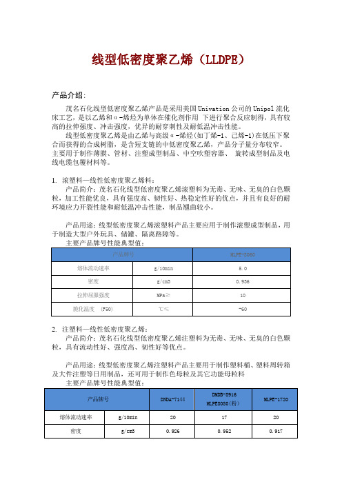
线型低密度聚乙烯(LLDPE)产品介绍:茂名石化线型低密度聚乙烯产品是采用美国Univation公司的Unipol流化床工艺,是以乙烯和α-烯烃为单体在催化剂作用下进行聚合反应制得,具有较高的拉伸强度、冲击强度,优异的耐穿刺性及耐低温冲击性能。
线型低密度聚乙烯是由乙烯与高级α-烯烃(如丁烯-1、己烯-1)在低压下聚合而获得的合成树脂,是含短支链的中低密度聚乙烯,产品分子量分布较窄。
主要用于制作薄膜、管材、注塑成型制品、中空吹塑容器、旋转成型制品及电线电缆包覆材料等。
1.滚塑料—线性低密度聚乙烯料:产品简介:茂名石化线型低密度聚乙烯滚塑料为无毒、无味、无臭的白色颗粒,加工性能优良,具有强度高、韧性好、热稳定性好的优点,并且有良好的耐环境应力开裂性能和耐低温冲击性能,制品翘曲较小。
产品用途:线型低密度聚乙烯滚塑料产品主要应用于制作滚塑成型制品,用于制造大型户外玩具、储罐、隔离路障等。
2.注塑料—线性低密度聚乙烯:产品简介:茂名石化线型低密度聚乙烯注塑料为无毒、无味、无臭的白色颗粒,具有流动性好、强度高、韧性好等优点。
产品用途:线型低密度聚乙烯注塑料产品主要用于制作塑料桶、塑料周转箱及大件注塑等日用制品,还可用于制作色母粒及其它功能母粒料3.薄膜料—线性低密度聚乙烯:产品简介:茂名石化线型低密度聚乙烯薄膜料为无毒、无味、无臭的白色颗粒,具有强度高、韧性好、刚性强、耐热、耐寒等优点,有良好的耐环境应力开裂、耐冲击、耐撕裂性能及抗穿刺性能,加工性能优良,薄膜制品的透明性和耐老化性能优异,并可耐酸、碱和有机溶剂。
产品用途:线型低密度聚乙烯薄膜料产品用于制作薄膜制品,如各种农膜、地膜、日用包装袋、垃圾袋,也可用于容器衬里、涂层、农用小口径排水管材等。
高密度聚乙烯产品概述:高密度聚乙烯是由乙烯与少量-烯烃单体共聚而成的高结晶非极性合成树脂,是在较低压力下合成,故又称“低压聚乙烯”。
其分子结构主要为线型结构,分子中支链少,结晶度高,密度大,具有较高的使用温度、硬度和机械强度,耐化学性能好。
7042 塑料
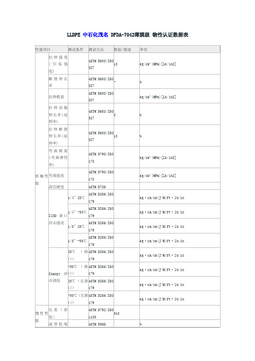
熔点
-
燃烧性 (率)
UL94
线性膨胀
ASTM D696/ISO
系数
11359
g/10min g/10min % ℃(℉) ℃(℉) ℃(℉) ℃(℉)
mm/mm.℃
%
率
ASTM
200℃/5kg D1238/ISO 2 熔融指数
1133 (流动系
ASTM 数)
220℃/10kg D1238/ISO
1133
吸水率
ASTM D570/ISO
23℃/24H
62
退火 热变形温
ASTM D648/ISO 75
度
ASTM D648/ISO
未退火
75
维卡软化 热性能 点
ASTM D1525/ISO R306
kg·cm/cm(J/M)ft·lb/in kg·cm/cm(J/M)ft·lb/in kg·cm/cm(J/M)ft·lb/in kg·cm/cm(J/M)ft·lb/in kg·cm/cm(J/M)ft·lb/in kg·cm/cm(J/M)ft·lb/in kg·cm/cm(J/M)ft·lb/in kg·cm/cm(J/M)ft·lb/in
527
拉伸断裂 伸长率(延 伸率)
ASTM D638/ISO 12
527
弯曲模量 (弯曲弹性 率)
ASTM D790/ISO 178
机 械 性弯曲强度 能
洛氏硬度
ASTM D790/ISO 178 ASTM D785
ASTM D256/ISO 1/4" 23℃
179
ASTM D256/ISO
1/4" -30℃
-30℃(无缺ASTM D256/ISO
科聚亚聚氨酯

cml7042英文说明书

© 2006 CML Microcircuits
2/5
Product Preview - CMX7032/CMX7042 - AIS Data Processor
Tx Modem Functions
• Configurable modulation type o AIS 25kHz channel (GMSK, 9600bps, 2.4kHz deviation, BT = 0.4)
o I and Q or two-point modulation
o Single and two-point modulation Tx outputs
• C-BUS serial interface
• Flexible powersave modes
• Low power 3V to 3.6V operation
Tx Section
Output Drivers
Rx Seቤተ መጻሕፍቲ ባይዱtion
GMSK Encoder
GMSK Decoder
FSK Decoder
GMSK Decoder
DACs
ADCs
GPIO
Dual Clock Generators Dual RF Synthesisers
(CMX7032 only)
Message Buffer
These devices utilise CML’s proprietary FirmASIC ® component technology. On-chip sub-systems are configured by a Function Image™: this is a data file that is uploaded during device initialisation and configures the device's function and feature set. The Function Image™ can be loaded automatically from an optional external EEPROM or from a host µController over the built-in C-BUS serial interface. The device's functions and features can be enhanced by subsequent Function Image™ releases, facilitating in-the-field upgrades.
- 1、下载文档前请自行甄别文档内容的完整性,平台不提供额外的编辑、内容补充、找答案等附加服务。
- 2、"仅部分预览"的文档,不可在线预览部分如存在完整性等问题,可反馈申请退款(可完整预览的文档不适用该条件!)。
- 3、如文档侵犯您的权益,请联系客服反馈,我们会尽快为您处理(人工客服工作时间:9:00-18:30)。
The SLA7042M and SLA7044M are designed for high-efficiency and high-performance microstepping operation of 2-phase, unipolar stepper motors. Microstepping provides improved resolution without limiting step rates, and provides much smoother low-speed motor operation. An automated, innovative packaging technology combined with power NMOS FETs and monolithic CMOS logic/control circuitry advances power multi-chip modules (PMCMs™) toward the complete integration of motion control. Each half of these stepper motor control-ler/drivers operate independently. The 4-bit shift registers are serially loaded with motor phase information and output current-ratio data (eight levels). The combination of user-selectable current-sensing resistor,linearly adjustable reference voltage, and digitally selected outputcurrent ratio provides users with a broad, variable range of of full, half,and microstepping motor control (I OUT ≈ [V REF /3 • R S ] • Current Ratio).Each PMCM is rated for a maximum motor supply voltage of 46 V and utilizes advanced NMOS FETs for the high-current, high-voltage driver outputs. The avalanche-rated (≥100 V) FETs provide excellent ON resistance, improved body diodes, and very-fast switching. The multi-chip ratings and performance afford significant benefits andadvantages for stepper drives when compared to the higher dissipation and slower switching speeds associated with bipolar transistors. Highly automated manufacturing techniques provide low-cost and exception-ally reliable PMCMs suitable for controlling and directly driving a broad range of 2-phase, unipolar stepper motors. The SLA7042M and SLA7044M are identical except for r DS(on) and output current plete applications information is given on the following pages.PWM current is regulated by appropriately choosing current-sensing resistors, a voltage reference, and digitally programmable current ratio.Inputs are compatible with 5 V logic and microprocessors.BENEFITS AND FEATURESs Cost-Effective, Multi-Chip Solution s ‘Turn-Key’ Motion-Control Module s Motor Operation to 3 A and 46 V s 3rd Generation High-Voltage FETs s 100 V, Avalanche-Rated NMOS s Low r DS(on) NMOS Outputss Advanced, Improved Body Diodes s Microstepping Unipolar Drives High-Efficiency, High-Speed PWMAlways order by complete part number: SLA7042M .Data Sheet 28202A*s Independent PWM Current Control (2-Phase)s Digitally Programmable PWM Current Controls Low Component-Count PWM Drive s Low Internal-Power Dissipation s Electrically Isolated Power Tab s Logic IC- and µP-Compatible Inputss Machine-Insertable Package™MOTOR CONTROLLER/DRIVERS115 Northeast Cutoff, Box 15036Worcester, Massachusetts 01615-0036 (508) 853-5000™FUNCTIONAL BLOCK DIAGRAMNote that channels A and B are electrically isolated.25151050TEMPERATURE in °C20Dwg. GK-018-1A L L O W AB L E P AC K A G E P O W E RD I S S I P A T I O N i n W A T T SALLOWABLE PACKAGEPOWER DISSIPATIONDwg. FK-006CONTROL SUPPLYOUT OUT CHANNEL A PIN NUMBERS CHANNEL B PIN NUMBERSCopyright © 1995, 1998 Allegro MicroSystems, Inc.DC ELECTRICAL CHARACTERISTICS at T A = +25°C, V DD = 5 V unless otherwise noted.Limits Characteristic Symbol Test Conditions Min Typ Max UnitsFET Leakage Current IDSS VDS= 100 V—— 4.0mAFET ON Voltage VDS(ON)SLA7042M, IOUT= 1.2 A——800mVSLA7044M, IOUT= 3 A——855mVFET ON Resistance rDS(on)SLA7042M, IOUT= 1.2 A——0.67ΩSLA7044M, IOUT= 3 A——0.285ΩBody Diode Forward Voltage VSD SLA7042M, IOUT= –1.2 A—— 1.2VSLA7044M, IOUT= –3 A—— 1.6VControl Supply Voltage VDDOperating 4.5 5.0 5.5VControl Supply Current IDD Each controller, VDD= 5.5 V——7.0mALogic Input Voltage VIN(1)3.5——VVIN(0)—— 1.5VLogic Input Current IIN(1)VIN(1)= VDD—— 1.0µAIIN(0)VIN(0)= 0——–1.0µAREF/ENABLE Input Voltage VREF/ENDATA, CLOCK, STROBE, and OUT Enabled0.4— 2.5VDATA, CLOCK, STROBE, and OUT Disabled VDD- 1——V REF/ENABLE Input Current I REF/EN0 V ≤ V REF/EN≤ 5 V——±1.0µA Step Reference SRCR DATA Input = 000X—0—% Current Ratio DATA Input = 001X—20—%DATA Input = 010X—40—%DATA Input = 011X—55.5—% First Bit Entered (X) = Phase DATA Input = 100X—71.4—% Second Bit Entered = LSB DATA Input = 101X—83—% Last Bit Entered = MSB DATA Input = 110X—91—%DATA Input = 111X—100—% NOTE: Negative current is defined as coming out of (sourcing) the specified device pin.TYPICAL AC CHARACTERISTICS at T A = +25°C, V DD = 5 V, I OUT = 1 A, Logic Levels are V DD and GroundPWM OFF Time DATA Input = 001X.................................................................7 µsDATA Input = 010X.................................................................7 µsDATA Input = 011X.................................................................9 µsDATA Input = 100X.................................................................9 µsDATA Input = 101X.................................................................9 µsDATA Input = 110X................................................................11 µsDATA Input = 101X................................................................11 µs Output RiseTime t r10% to 90%...........................................................................0.5 µsOutput Fall Time t f90% to 10%...........................................................................0.1 µsStrobe-to-Output Switching Time t pd50% to 50%...........................................................................0.7 µs MOTOR CONTROLLER/DRIVERSMOTOR CONTROLLER/DRIVERS115 Northeast Cutoff, Box 15036Worcester, Massachusetts 01615-0036 (508) 853-5000™Dwg. WK-002SERIAL PORT TIMING CONDITIONS(T A = +25°C, Logic Levels are V DD and Ground)A. Minimum Data Active Time Before Clock Falling Edge (Data Set-Up Time)........... 150 nsB. Minimum Data Active Time After Clock Falling Edge (Data Hold Time).................. 150 nsC. Minimum Data Pulse Width...................................................................................... 350 nsD. Minimum Clock Pulse Width .................................................................................... 350 nsE. Minimum Time Between Clock and Strobe Falling Edges ....................................... 650 nsF. Minimum Strobe Pulse Width...................................................................................500 nsAPPLICATIONS INFORMATIONThe SLA7042M and SLA7044M modules integrate two CMOS controller ICs and four NMOS FETs. Each half of the device operates independently, although the CLOCK inputs may be connected together and the STROBE inputs may be connected together. Pulling V REF/EN low (<2.5 V) allows the 4-bit shift registers to be serially loaded with motor phase and output currrent ratioing data.The first bit selects the motor phase (logic high = Output A or B, logic low = Output A or B); the next three bits determine the motor current ratio (eight steps, 0% to 100%). The internal D/A converter, in conjunction with a current-sensing resistor and input reference voltage, completes the microstepping current control.Pulling V REF/EN high (within 1 V of V DD ) resets the shift register and latches to turn the MOS drivers OFF and inhibits the serial DATA input.FIGURE 2.␣ PWM CONTROL (RUN MODE)V V SERIAL DATASERIAL DATA INPUT ENABLEIn a minimum-component application, a voltage divider provides V REF/EN and an npn transistor provides the required pull-down to enable the serial data input as shown in Figure 2.I OUT max ≈R 2•V b R 1 + R 23 •R SµP STEPPER MOTOR CONTROLAlternative REFERENCE/ENABLE input configura-tions provide for more complete motor control. A tri-state logic element and a voltage divider allows a fixed refer-ence voltage, with both output disable and data enable functions. Complete µP control is usually accomplished with a D/A converter as shown in Figure 3. Here, digital control provides an output disable (>V DD - 1 V), V REF , and V EN (<2.5 V).MOTOR CONTROLLER/DRIVERSDwg. WK-001PHASE APHASE AIOUTREGULATING THE PWM OUTPUT CURRENTThe output current (and motor coil current) waveform is illustrated in Figure 1. Setting the maximum PWM current trip point to meet the specified full-step running current for the motor, I OUT max (DATA input = 111X =100% ratio), requires only a current-sensing resistor, R S ,and an input reference voltage, V REF/EN , between 0.4 V and 2.5 V.I OUT max ≈V REF/EN 3 •R SFIGURE 1.␣ PHASE A COIL CURRENT WAVEFORMMOTOR CONTROLLER/DRIVERS115 Northeast Cutoff, Box 15036Worcester, Massachusetts 01615-0036 (508) 853-5000™V V FIGURE 3. ␣C OMPLETE CONTROLSERIAL DATA INPUTThe serial DATA input port is enabled (active low) by the REFERENCE/ENABLE input. When V REF/EN is be-tween 0.4 V and 2.5 V, information on the DATA input is read into the shift register on each high-to-low transition of the CLOCK.There are four bits: the first bit entered controls theFIGURE 4. ␣T IMING RELATIONSHIPSmotor phase — a high level enables OUT A or OUT B , a low level enables OUT A or OUT B . The next three bits set the step reference voltage ratio and PWM OFF time as shown in the Characteristics Tables — the least-significant bit first and the most-significant bit last.Data written into the serial data port is latched and becomes active on a high-to-low transition at STROBE.Dwg. WK-003REFERENCE/ENABLE INPUTThe serial DATA input port is enabled (active low) by the REFERENCE/ENABLE input when V REF/EN is between 0.4 V and 2.5 V. With V REF/EN greater than V DD - 1 V, the serial DATA input port is disabled, the outputs are OFF,and the controller/driver will not be affected by changes at the DATA, CLOCK, or STROBE inputs.With V REF/EN between 0.4 V and 2.5 V, the output current limit is a linear function of V REF and the step reference current ratio.I OUT ≈ V REF•SRCR3 •R S In a typical (SLA7042M) application where V DD = 5 V,a V REF/EN between 0.4 V and 2.5 V, and a maximumallowable load current of 1.2 A, the maximum value of R S is 0.69 Ω and I OUT min is 0.11 A when SRCR is 100%(DATA input = 111X).POWER DISSIPATION CALCULATIONSThe SLA7042/44M normally do not require special heat sinking except under unusual circumstances (two phases operating near maximum output current and T A >65°C). However, as with all power drivers, the basic constituents of power dissipation should be evaluated.Conduction losses (internal power dissipation) include:(a)FET output power dissipation (I OUT 2 • r DS(on) or I OUT • V DS(ON)),(b)FET body diode power dissipation (V SD • I OUT ), and (c)control circuit power dissipation (V DD • I DD ).PACKAGE RATINGS/DERATING FACTORSThermal calculations must also consider the tempera-ture effects on the output FET ON resistance. The appli-cable thermal ratings for the 18-lead power-tab SIP PMCM package are:R θJA = 28°C/W (junction to ambient with no heat sink)or 4.5 W at +25°C and a derating factor of -36 mW/°C for operation above +25°C.R θJM = 5°C/W (junction to mounting surface).TEMPERATURE EFFECTS ON FET r DS(on)Analyzing safe, reliable operation includes a concern for the relationship of NMOS ON resistance to junction temperature. Device package power calculations must include the increase in ON resistance (producing higher output ON voltages) caused by higher operating junction temperatures. Figure 5 provides a normalized ON resis-tance curve, and all thermal calculations should consider increases from the given +25°C limits, which may be caused by internal heating during normal operation.FIGURE 5.␣ NORMALIZED ON RESISTANCEvs TEMPERATURE 2.01.0-40+80+1600.5JUNCTION TEMPERATURE in °CN O R M A L I Z E D F E T O N R E S I S T A N C EDwg. GK-0171.52.5+40+120The power MOSFET outputs of these devices are similar to the International Rectifier type IRL510(SLA7042M) and IRL520 (SLA7044M). These devices feature an excellent combination of fast switching, rugged-ized device design, low on-resistance, and cost effective-ness.SLA7042M AND SLA7044M MICROSTEPPING,UNIPOLAR PWM, HIGH-CURRENT MOTOR CONTROLLER/DRIVERSSLA7042M AND SLA7044M MICROSTEPPING,UNIPOLAR PWM, HIGH-CURRENTMOTOR CONTROLLER/DRIVERS115 Northeast Cutoff, Box 15036Worcester, Massachusetts 01615-0036 (508) 853-5000™±NOTES: 1. Exact body and lead configuration at vendor’s option within limits shown.2. Recommended mounting hardware torque: 4.34 – 5.79 lbf•ft (6 – 8kgf•cm or 0.588 – 0.784 Nm).3. The shaded area is exposed (electrically isolated) heat spreader.4. Recommend use of metal-oxide-filled, alkyl-degenerated oil base,silicone grease (Dow Corning 340 or equivalent).±Dimensions in Inches (for reference only)Dimensions in Millimeters (controlling dimensions)The products described here are manufactured in Japan by Sanken Electric Co.,Ltd. for sale by Allegro MicroSystems, Inc.Sanken Electric Co., Ltd. and Allegro MicroSystems, Inc. reserve the right to make, from time to time, such departures from the detail specifications as may be required to permit improvements in the design of their products.The information included herein is believed to be accurate and reliable.However, Sanken Electric Co., Ltd. and Allegro MicroSystems, Inc. assume no responsibility for its use; nor for any infringements of patents or other rights of third parties which may result from its use.This datasheet has been download from: Datasheets for electronics components.。