MCU111+Technical+Reference2
伊顿 用于馈电线路 开关设备和变压器保护的15.5 kV E额定中压熔断器 数据表

Description:• Bussmann™ series of E-Rated, current-limiting, medium voltage fuses are for feeder circuit, switchgear and transformer protection.Features and benefits• Current-limiting E-Rated medium voltage fuses are defined by their melting time-current characteristic that permit their electrical interchangeability with other fuses of the same E Rating.• E-Rated fuses must have a defined current response time specified by ANSI C37.46.E-Rated fuses of 100 amps and below must melt in 300 seconds at an RMS current within the range of 200% to 240% of the fuse’s nameplate current rating. E-Rated fuses greater than 100 amps must melt within 600 seconds at an RMS current in the range of 220% to 264% of the fuse’s nameplate current rating.• E-Rated fuses are physically dimensioned for easy installation in existing hardware.• Current-limiting fuses provide positive interruption even on low fault currents. The fuse limits the magnitude of electromechanical stresses in the protected apparatus.• Constructions available in ferrule, bolt-onand clip-lock, and specialty mount fuses for AMPGARD motor starters.• Outdoor rating available on select catalog numbers (requires installation in a suitable enclosure).• Open fuse indicator speeds troubleshootingby providing a positive visual indication of fuse operation.• 50/60 Hz operating frequency for worldwide application.• Mountings are available in disconnect and non-disconnect versions with porcelain or glass poly-ester insulators.• Live parts and end fittings available.T ypical applications:• Medium voltage transformer primaryprotection• Medium voltage feeder circuit protection • Medium voltage switches• Medium voltage metal-enclosed switchgear15.5 kV E-Rated medium voltage fuses for feedercircuit, switchgear and transformer protection2Technical Data 10353Effective November 201915.5 kV E-Rated medium voltage fuses forfeeder circuit, switchgear and transformer protection/bussmannseriesE-Rated medium voltage ferrule fusesCatalog symbols:•General purpose• 15CLE-_E-D (long construction, 10-25 A)• 15CLE-_E (long construction, 15-300 A)• 15HLE-_E (short construction, 10-250 A)•15LHLE-_E (intermediate construction, 65-300 A)•Full range (per ANSI C37.40)•MV155F_Ratings*:• Volts — 15.5 kV • Amps — 10 to 300 A•Interrupting ratings — 31.5 to 63 kA RMS Sym.* See catalog number tables for voltages, ampacities and interrupting ratings by catalog number.Agency information:•E-Rated fuses meet the performance characteristics of ANSI C37.46•UL ® Listed, Guide JEEG, File E240398. See catalog numbers.Dimensions (see catalog number tables for values)Recommended fuseclips and holders:65E–100E Single barrel 3 (76)18 (457)20.53 (521)Disconnect †—Not available Not available CLE-DL-D CLE-DF-D 125E–300E Double barrelNon-disconnect— 3 (76)18 (457)20.53 (521)Not available Not available CLE-NL-E —Disconnect†—Not availableNot availableCLE-DL-ECLE-DF-E** End fittings supplied only when required.† Disconnect mountings provide a means for fuse extraction only. Do not use a disconnect mounting for load switching or fuse removal while energized.3Technical Data 10353Effective November 201915.5 kV E-Rated medium voltage fuses forfeeder circuit, switchgear and transformer protection/bussmannseriesCLE, HLE and LHLE Type general purpose fuses20.5 (521) 3 (76)18 (457)501Indoor/outdoor8015LHLE-80E 10015LHLE-100E 125215LHLE-125E-D 15015LHLE-150E-D 17515LHLE-175E 20015LHLE-200E 25015LHLE-250E 30015LHLE-300E* Fuses conform to dimensional standards established by Westinghouse.† UL Listed, Guide JEEG, File E240398.4Technical Data 10353Effective November 201915.5 kV E-Rated medium voltage fuses forfeeder circuit, switchgear and transformer protection/bussmannseriesFigure 2Figure 3Figure 1MV155F_ Full range18.7 (475) 2 (51)15 (381)501Indoor7MV155F1CBX7E 10MV155F1CBX10E 10 3 (76)MV155F1DBX10E 15 2 (51)MV155F1CBX15E 15 3 (76)MV155F1DBX15E 20 2 (51)MV155F1CBX20E 20 3 (76)MV155F1DBX20E 25 2 (51)MV155F1CBX25E 25 3 (76)MV155F1DBX25E 30 2 (51)MV155F1CBX30E 30 3 (76)MV155F1DBX30E 40MV155F1DBX40E 50MV155F1DBX50E 65MV155F1DBX65E 6521.7 (551)18 (457)MV155F1DCX65E 8018.7 (475)15 (381)MV155F1DBX80E 8021.7 (551)18 (457)MV155F1DCX80E 10018.7 (475)15 (381)MV155F1DBX100E 10021.7 (551)18 (457)MV155F1DCX100E 12518.7 (475)15 (381)2MV155F2DBX125E 12521.7 (551)18 (457)MV155F2DCX125E 15018.7 (475)15 (381)MV155F2DBX150E 15021.7 (551)18 (457)MV155F2DCX150E 17518.7 (475)15 (381)MV155F2DBX175E 17521.7 (551)18 (457)MV155F2DCX175E 20018.7 (475)15 (381)MV155F2DBX200E 20021.7 (551)18 (457)MV155F2DCX200ERecommended CLE, HLE and MV155 fuseclips1Enclosed fuseclip 3 (76)4.14 (105)2.45 (62)3.01 (76)1.19 (30)5.64 (143)1.51 (38)0.4 (10)A3354730*Open fuseclip2See dimensions drawing1A0065Spring loaded open fuseclip39078A67G04*For single barrel applications only. Not sold in pairs.5Technical Data 10353Effective November 201915.5 kV E-Rated medium voltage fuses forfeeder circuit, switchgear and transformer protection/bussmannseries 15.5 kV time-current curves — minimum melt for MV155 2 inch diameter fusesT I M E I N S E C O N D SAMPERE RATING1,0007,00010010CURRENT IN AMPERES30A25A 20A 15A 10A7A 5A 100101.1.01MV155_ (2 inch diameter)6Technical Data 10353Effective November 201915.5 kV E-Rated medium voltage fuses forfeeder circuit, switchgear and transformer protection/bussmannseries15.5 kV time-current curves — total clear for MV155_ 2 inch diameter fusesT I M E I N S E C O N D S100101.1.0130A25A 20A 15A 10A7A 5A AMPERE RATING1,0007,00010010CURRENT IN AMPERESMV155_ (2 inch diameter)7Technical Data 10353Effective November 201915.5 kV E-Rated medium voltage fuses forfeeder circuit, switchgear and transformer protection/bussmannseries 15.5 kV time-current curves — minimum melt for MV155_ 3 inch diameter fusesMV155_ (3 inch diameter).1101001000.0111001010001000020000T I M E I N S E C O N D SCURRENT IN AMPERES10A15A 20A 25A 30A 40A 50A 65A 80A 100A125A 150A 175A200A8Technical Data 10353Effective November 201915.5 kV E-Rated medium voltage fuses forfeeder circuit, switchgear and transformer protection/bussmannseries15.5 kV time-current curves — total clear for MV155_ 3 inch diameter fusesMV155_ (3 inch diameter)T I M E I N S E C O N D SCURRENT IN AMPERES.1101001000.011100001000101002000010A 15A 20A 25A 30A 40A50A 65A 80A 100A125A 150A 175A200A9Technical Data 10353Effective November 201915.5 kV E-Rated medium voltage fuses forfeeder circuit, switchgear and transformer protection/bussmannseries 15.5 kV peak let-through for MV155_ 2 and 3 inch diameter fusesMV155_ (2 and 3 inch diameter)1AVAILABLE CURRENT IN KILOAMPERES (RMS Symmetrical)M A X I M U M L E T -T H R O U G H (P e a k K i l o a m p e r e s )10010.1.111010015A 20A 25A 30&40A 50A 65A80A 100A 07&10A 05A125A 150A 175A 200A AB10Technical Data 10353Effective November 201915.5 kV E-Rated medium voltage fuses forfeeder circuit, switchgear and transformer protection/bussmannseries15.5 kV time-current curves — minimum melt for 15LHLE_ 3 inch diameter fusesCURRENT IN AMPERES15LHLE_ (3 inch diameter)Curve TC66703203April 201115.5 kV time-current curves — total clear for 15LHLE_ 3 inch diameter fusesCURRENT IN AMPERES 15LHLE_ (3 inch diameter)Curve TC66703303April 201111 /bussmannseries/bussmannseries15.5 kV peak let-through for 15LHLE_ 3 inch diameter fusesP e a k I n s t a n t a n e o u s L e t -T h r o u g h C u r r e n t i n K i l o -a m p e r i e sCURRENT IN AMPERES15LHLE_ (3 inch diameter)Curve TC70547404April 201113/bussmannseriesCLE and HLE type mountings - in (mm)15HLE-GNM-E 16.25 (412.7) 6 (152.4)25 (635)0.62 (15.7)1.75 (44.4)7 (177.8)14.98 (380.5)9515HLE-PNM-E16.25 (412.7)6 (152.4)25 (635)0.62 (15.7)1.75 (44.4)7 (177.8)14.98 (380.5)95CLE and HLE T ype disconnect mounting †CLE and HLE Type non-disconnect mountingdisconnect mounting for load switching or fuse removal while energized.•••Agency information:• E-Rated fuses meet the performance characteristics of•Indicator to be(53.8)Indicator to beHCL0.25X.XX (XX.X)* Flush with surface in untripped position, trip force is 2 lb (0.9kg)/bussmannseriesBHCL, BHLE and HCL type fuses22.8 (579) 3 (76)N/A631Indoor1515HCL-15E 2015HCL-20E 2515HCL-25E 3015HCL-30E 4015HCL-40E†5015HCL-50E†6515HCL-65E†8015HCL-80E†10015HCL-100E†125215HCL-125E-D†15015HCL-150E†17515HCL-175E†20015HCL-200E†25015HCL-250E†30015HCL-300E†† UL Listed, Guide JEEG, File E240398.15/bussmannseries15.5 kV time-current curves — minimum melt for 15CLE-_E and 15CLE-_-D15CLE-_Curve 70548501April 16, 1999Reference # 563532Curve 70546801 April 1999Reference # 705468Curve 70547001 April 1999 Reference # 705470/bussmannseries15.5 kV time-current curves — total clear for 15CLE-_E and 15CLE-_-D15CLE-_Curve 70548601April 16, 1999Reference # 563533Curve 70546901April 1999Reference # 705469Curve 70547101April 1999Reference # 70547117/bussmannseries15.5 kV peak let-through for 15CLE-_E and 15CLE-_-D15CLE-_Curve 70548802 September 1999Reference # 705488Curve 70547501 September 1999 Reference # 705475/bussmannseries15.5 kV time-current curves — minimum melt for 15HLE-_E and 15BHLE-_E15HLE-_, 15BHLE-_Curve 70548507 April 16, 1999Reference # 563532Curve 70546601April 1999Reference # 70546619/bussmannseries15.5 kV time-current curves — total clear for 15HLE-_E and 15BHLE-_E15HLE-_, 15BHLE-_Curve 70548607 April 16, 1999Reference # 563533Curve 70546701 April 1999 Reference # 705467/bussmannseries21Technical Data 10353Effective November 201915.5 kV E-Rated medium voltage fuses forfeeder circuit, switchgear and transformer protection/bussmannseries15.5 kV peak let-through for 15HLE-_E and 15BHLE-_E15HLE-_, 15BHLE-_Curve 70548805September 1999Reference # 705488Curve 70547401September 1999Reference # 70547422Technical Data 10353Effective November 201915.5 kV E-Rated medium voltage fuses forfeeder circuit, switchgear and transformer protection/bussmannseries15.5 kV time-current curves — minimum melt for 15HCL -_E15HCL-_Curve 70548503Janaury 2001Curve 66703201January 200123Technical Data 10353Effective November 201915.5 kV E-Rated medium voltage fuses forfeeder circuit, switchgear and transformer protection/bussmannseries15.5 kV time-current curves — total clear for 15HCL -_E15HCL-_Curve 70548603Janaury 2001Curve 66703301January 200124Technical Data 10353Effective November 201915.5 kV E-Rated medium voltage fuses forfeeder circuit, switchgear and transformer protection/bussmannseries15.5 kV peak let-through for 15HCL -_E15HCL-_Curve 70548803Janaury 2001Curve 70547402Janaury 200125The only controlled copy of this Data Sheet is the electronic read-only version located on the Bussmann Network Drive. All other copies of this document are by definition uncontrolled. This bulletin is intended to clearly present comprehensive product data and provide technical information that will help the end user with design applications. Bussmann reserves the right, without notice, to change design or construction of any products and to discontinue or limit distribution of any products. Bussmann also reserves the right to change or update, without notice, any technical information contained in this bulletin. Once a product has been selected, it should be tested by the user in all possible applications.Eaton and Bussmann are valuable trademarks of Eaton in the U.S. and other countries. Y ou are not permitted to use the Eaton trademarks without prior written consent of Eaton.ANSI is a registered trademark of the American National Standards AssociationIEEE is a registered trademark of the Institute of Electrical and Electronics Engineers NEMA is a registered trademark of the National Electrical Mfgrs. AssociationNFPA is a registered trademark of the National Fire Protection AssociationUL is a registered trademark of the Underwriters Laboratories, Inc.Eaton1000 Eaton Boulevard Cleveland, OH Bussmann Division 114 Old State Road Ellisville, MO 63021United States/bussmannseries © 2019 EatonAll Rights Reserved Publication No. 10353November 2019For Eaton’s Bussmann series product information,call 1-855-287-7626 or visit:/bussmannseriesFollow us on social media to get the latest product and support information.。
MT9M111中文资料

sophisticated processing: Color recovery and correction Sharpening, gamma, lens-shading correction On-the-fly defect correction • Filtered image downscaling to arbitrary size with smooth, continuous zoom and pan • Automatic Features: Auto exposure, auto white balance (AWB), auto black reference (ABR), auto flicker avoidance, auto color saturation, auto defect identification and correction • Fully automatic Xenon and LED-type flash support Fast exposure adaptation • Multiple parameter contexts Easy/fast mode switching • Camera control sequencer automates: Snapshots Snapshots with flash Video clips • Simple two-wire serial programming interface • ITU-R BT.656 (YCbCr), 565RGB, 555RGB, or 444RGB formats (progressive scan) • Raw and processed Bayer formats • Output FIFO and integer clock divider: “Uniform” pixel clocking
PSoC 62 数据手册说明书

■ 1 MB 应用闪存,32 KB EEPROM 区域和 32 KB 监控闪存
■ 6 个过压容限 (OVT) 引脚
■ 128 位宽闪存访问降低功耗
封装
■ SRAM 具有可选择的保留粒度
■ 124-BGA (评定中)
■ 288 KB 集成 SRAM
■ 80-WLCSP
■ 32 KB 保留边界 (可以保留 32K 到 288K,增量为 32K)
■ 锁相环 (PLL),用于倍增时钟频率 ■ 8 MHz 内部主振荡器 (IMO),精度为2% ■ 超低功耗 32-kHz 内部低速振荡器 (ILO),精度为±10% ■ 频率锁定环 (FLL),用于倍增 IMO 频率
串行通信 ■ 九个独立的运行时可重配置串行通信模块 (SCB),每个都可以
软件配置为 I2C,SPI 或 UART
■ 提供具有 Smart_IO 块的两个端口,能力; 这些在深度睡眠期间 可用
■ 安全引导不间断,直到系统保护属性建立 ■ 在引导期间使用硬件散列 (Hashing) 进行身份验证 ■ 逐步验证执行映像
电容式感应
■ 在受保护程序的只执行模式下安全执行代码
■ 赛普拉斯 CapSense Sigma-Delta (CSD) 提供一流的 SNR, 液体容差和接近感应
■ 12 位 1 Msps 的 SAR ADC 包括差分模式、单端模式和具有信 ■ 集成开发环境提供原理图设计输入和构建 (具有模拟和数字自动
号求平均功能的 16 通道序列发生器。
路由) 和代码开发和调试功能
■ 一个 12 位电压模式 DAC,稳定时间小于 5μs
■ 应用编程接口 (API) 可用于所有固定功能和可编程的外设
特性
32位双核CPU子系统 ■ 具有单周期倍频的 150-MHz Arm Cortex-M4F CPU (浮点和存
Kinetix 5500伺服驱动器用户手册说明书

Kinetix 5500 伺服驱动器产品目录号 2198-H003-ERS、2198-H008-ERS、2198-H015-ERS、2198-H025-ERS、2198-H040-ERS、2198-H070-ERS、2198-H003-ERS2、2198-H008-ERS2、2198-H015-ERS2、2198-H025-ERS2、2198-H040-ERS2、2198-H070-ERS2、2198-CAPMOD-1300本手册链接到 Kinetix 5500 Servo Drive Fault Codes Reference Data (出版号: 2198-RD005),以供故障代码查询。
可下载电子表格,以便离线访问。
2罗克⻙尔⾃动化出版物 2198-UM001L-ZH-P - 2022 年 2 月Kinetix 5500 伺服驱动器⽤⼾⼿册⽤⼾重要须知在安装、配置、操作或维护本产品之前,请阅读本文档以及“其他资源”章节所列的文档,了解关于安装、配置和操作该设备的信息。
除了所有适用的条例、法律和标准的要求之外,用⼾还必须熟悉安装和接线说明。
包括安装、调整、投⼊运⾏、使用、装配、拆卸和维护等在内操作必须由经过适当培训的⼈员根据适用的操作守则来执⾏。
如果未遵照制造商所指定的方式使用该设备,将可能导致该设备提供的保护失效。
在任何情况下,对于因使用或操作该设备造成的任何间接或连带损失,罗克⻙尔⾃动化公司概不负责。
本手册中包含的示例和图表仅用于说明。
由于任何具体安装都涉及众多变数和要求,罗克⻙尔⾃动化公司对于依据这些示例和图表所进⾏的实际应用不承担任何责任和义务。
对于因使用本手册中所述信息、电路、设备或软件而引起的专利问题,罗克⻙尔⾃动化公司不承担任何责任。
未经罗克⻙尔⾃动化公司的书⾯许可,不得复制本手册的全部或部分内容。
在整本手册中,我们在必要的地方使用了以下注释,来提醒您留意安全注意事项。
设备表⾯或内部还可能贴有以下标签,而标签上给出了具体的预防措施。
MCU升级指导书
1. 升级指导书1.1. 升级文件清单mcu-boot.bin :MCU最小系统的升级软件;mcu-soft.exe :MCU主机软件的压缩包。
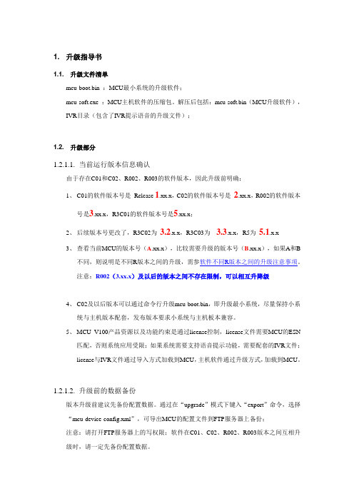
解压后包括:mcu-soft.bin(MCU升级软件),IVR目录(包含了IVR提示语音的升级文件);1.2. 升级部分1.2.1.1.当前运行版本信息确认由于存在C01和C02、R002、R003的软件版本,因此升级前明确:1、C01的软件版本号是Release 1.xx.x,C02的软件版本号是2.xx.x,R002的软件版本号是3.xx.x,R3C01的软件版本号是5.xx.x;2、后续版本号更改了,R3C02为3.2.x.x,R3C03为 3.3.x.x,R5为5.1.x.x3、查看当前MCU的版本号(A.xx.x),比较需要升级的版本号(B.xx.x),如果A和B不同,则说明是不同R版本之间的升级,需参软件不同R版本之间的升级注意事项。
注意:R002(3.xx.x)及以后的版本之间不存在限制,可以相互升降级4、C02及以后版本可以通过命令行升级mcu-boot.bin,即升级最小系统,尽量保持小系统与主机版本配套,发布版本要求小系统与主机板本兼容。
5、MCU V100产品资源以及功能约束是通过license控制,license文件需要MCU的ESN匹配,否则系统应用受限;如果系统需要支持语音提示功能,需要配套的IVR文件;license与IVR文件通过导入方式加载到MCU,主机软件通过升级方式,加载到MCU。
1.2.1.2.升级前的数据备份版本升级前建议先备份配置数据。
通过在“upgrade”模式下键入“export”命令,选择“mcu-device-config.xml”,可导出MCU的配置文件到FTP服务器上备份;注意:请打开FTP服务器上的写权限;软件在C01、C02、R002、R003版本之间互相升级时,请一定先备份配置数据。
1.2.1.3.软件加载准备MCU的软件升级,需要在一台电脑上安装FTP服务器,之后MCU通过命令行或网管从FTP服务器上下载升级软件,并保存到MCU的Flash中,完成升级过程。
NVIDIA Jetson JN30D技术参考手册说明书

AUVIDEAJN30D TECHNICAL REFERENCE MANUALSCOPE OF WORKProviding technical information and documentation to the product line JN30D for NVIDIA Jetson Nano & TX2 NX & Xavier NXPCB NUMBER38488ISSUE DATE [REVISED DATE]DEC.2021 [FEB.2022]Version1.2PAGES27CONTENTSSECTION 1Document revisions and changes (4)SECTION 2Product revisions and changes (5)SECTION 3Overiew (6)3.1Jetson compute module (6)3.2JN30D (6)3.3Model pictures (6)3.4JN30D features and comparison (7)3.5Technical specifications (8)3.6Power consumption (8)3.7Options (8)SECTION 4Features (9)4.1GPIO-Header (9)4.2Crypto chip (9)4.3MCU 9SECTION 5Pinout description (10)5.1J3 - Ethernet (GbE) (10)5.2J4 - M.2 PCIEx4 NVME SSDs (10)5.3J5 - CSI-2 CD (10)5.4J8 - USB 2.0 (11)5.5J9 - HDMI (11)5.6J10 - CSI-2 AB (11)5.7J11 - USB 3.0 – 3.1 (12)5.8J12 – USB-C (12)5.9J14 - UART connector (12)5.10J32 - Button and LED header (13)5.11J36 - Fan connector (13)5.12P11 - PoE connector (14)5.13P12 - GPIO header (14)5.14U10 - Crypto chip (15)5.15LED - M.2 (15)5.16LED - Eth (15)5.17LED - PWR (16)SECTION 6FAQ (17)SECTION 7Disclaimer (18)SECTION 8Copyright notice (19)SECTION 9Appendix A [CSI-Cameras] (20)9.1Camera connection example (20)SECTION 10Appendix B [GPIO] (21)10.1GPIO control (21)10.2Pin to GPIO reference sheet for Xavier-NX/Nano/TX2-NX (22)10.3How to calculate GPIOs (23)SECTION 11Appendix C [I2C] (25)11.1I2C device bus (25)11.2I2C usage of devices and registers (25)SECTION 12END OF DOKUMENT (27)SECTION 1Document revisions and changesDocument version Changes1.0 Initial document, internal verification process 1.1 Internal verification process1.2 Updated contents, new picturesSECTION 2Product revisions and changesProduct version Changes38488 Engineering prototype 38488 Production releaseSECTION 3Overiew3.1Jetson compute moduleThis new JN30D carrier board has been designed primarily for the Jetson Nano compute modules. When using other modules like the Jetson NX power limits may be exceeded as the USB C power supply only supplies up to 3A. More power may be supplied to the board via the two 5V pins on the GPIO header. In this case the USB supply should not be connected.3.2JN30D▪Easy integration into passively cooled systems▪Optionally available as complete system in passively cooled enclosure▪Easy flashing: just connect a USB OTG cable (Auto Flash)▪High performance storage: M.2 NVME PCIe x43.3Model picturesTop side Bottom sideJN30DJN30DThe 40 pin GPIO header is included (but not soldered in).3.4 JN30D features and comparisonDescriptionJN30DNVIDIA DevkitPower6V - 19V (5.5/2.5mm connector) 5V – 19V NX powering 5V 8A power supply ? DP no yes HDMIyes yes Fan connector yes yes M.2 NVME Key M yesyes Micro SD card no (optional)no M.2 Key E only with external module (using internal USB - J8) yesCAN RX / TX no (optional) yesUSB 3.0 1x USB 3.1(native - full performance) 4x USB 3.1(via USB hub - shared) Micro USB 1x Micro USB(host and device mode) 1x Micro USB(device mode only) Auto Flashing yes(plug in host cable and flash) noUSB 2.0 1x USB 2.0 (JST-GH, J8) noEthernet Gigabit RJ45 (one LED) Gigabit RJ45 (2 LEDs) PoE option yes - P11yes CSI 2x CSI-2 (4 lanes) plus camera LED (hardware sync available)2x CSI-2UART 2x (J14 and 40 pin GPIO header) 2x (40 pin header) I2C 2x (40 pin header) 2x (40 pin header) I2S 1x (40 pin header)(5V tolerant, unidirectional) 1x (40 pin header) SPI 2x (40 pin header)(5V tolerant, unidirectional) 2x (40 pin header) GPIO3x in + 3x out (40 pin header) (5V tolerant, unidirectional) 6x bi dir (40 pin header)Additional features Protection overvoltage protection (TVS diode)?Level shifters unidirectional level shifters (work better) bi dir (can cause problems) Expandability 1. Fully populated variants available no 2. Add-on boards for more USB and Ethernet 3. IMU4. board EEPROM and crypto chip (for SW copy protection)5. PCIe x1 connector6. LM823 WIFI module7. 2 more CSI-2 interfaces (2 lanes each) 8. RTC battery (rechargeable)9. Over current fuse (product safety) 10. UPS option for graceful power down11. On board MCU for watchdog and remote power cycle (LTE)3.5Technical specificationsDescription NoteHDMI standard HDMI connector (2.0)USB 3 5Gb/s or 10Gb/sPhysical size 80x 104.6mmMounting holes 4x M3Temperature range 0 to 70°C (extended range optional)Humidity noncondensingLongevity no temperature sensitive components(like electrolytic capacitors)3.6Power consumptionDescription JN30DCarrier board logic < 1 watt3.3V power converter efficiency > 90%3.7Options▪Flexible design and manufacturing▪designed and manufactured in Germany▪in-house fully automated production line with 3D AOI▪special configuration possible with minimum purchase quantity (display port, M.2, PoE, 48V power in, super cap option, 2 RPi camera module connectors, SPI, I2C, switches, etc.) ▪design services: you architect your custom carrier board and Auvidea designs and produces it - please ask for a quoteSECTION 4Features4.1GPIO-HeaderA 40 pin 2.54mm header for GPIO, I2C, I2S and UART. Die pinout is similar to the GPIO header on the NVIDIA dev kits and on the Raspberry Pi. Please note that all signals (except I2C) have uni-directional level shifters. In other boards some of these signals may be bi-directional which may cause compatibility issues. Auvidea does not guarantee the compatibility to any specific add-on boards. Please check the compatibility yourself. Some signals are 5V tolerant inputs and therefore may be driven from 5V logic outputs.The 40 pin GPIO header is included (but not soldered in).4.2Crypto chipThe crypto chip has been added to support software licensing and copy protection. Please check the data sheet of the manufacturer for details.Model: ATSHA204A-MAHCZ-Thttps:///downloads/en/DeviceDoc/ATSHA204A-Data-Sheet-40002025A.pdf4.3MCUA MCU for additional power management and watchdog functions is optional. It is standard on some of the extended versions of the JN30D.SECTION 5Pinout descriptionPlease note that the software GPIO number differs from the socket pin number. This software GPIO number must be computed with a special formula and differs between the various compute modules. Please see appendix B for details.5.1J3 - Ethernet (GbE)Standard RJ45 pinout with PoE capable magnetics class 3 and 4 (PD or PSE). Connected to the Ethernet controller on the compute module.5.2J4 - M.2 PCIEx4 NVME SSDsPlease note that only NVME SSDs are supported. SATA SSDs are not supported. We recommend the 128GB Transcend SSDs (TS128GMTE110S). This SSD is standard in some of the Auvidea development system offerings.5.3J5 - CSI-2 CD22 pin 0.5mm pitch FPC connectorPin Description Socket pin Note1 3.3V Power: connected with bead to 3.3V(5V optional if bead is moved)2 GEN1_I2C_SDA 1873 GEN1_I2C_SCL 1854 GND5 CAM2-MCLK IN: Input - connect to 1.8V or 3.3V output of the camera todrive the CAM LED.1: enable CAM LED0: disable CAM LED6 CAM2_PWDN 206 OUT: Output (open drain with 2.2k pullup to 3.3V) - connectto power enable of camera. The control signal is connectedvia level shifting inverter to pin 152 of the compute module.7 GND8 CSI_D_D1_P 669 CSI_D_D1_N 6410 GND11 CSI_D_D0_P 4212 CSI_D_D0_N 4013 GND14 CSI_C_CLK_P 5415 CSI_C_CLK_N 5216 GND17 CSI_C_D1_P 6018 CSI_C_D1_N 5819 GND20 CSI_C_D0_P 4821 CSI_C_D0_N 4622 GNDPlease note that on the JN30D each camera connector uses its own I2C bus. This setup is different from the NVIDIA dev kit. If you like to use CSI-2 cameras, please install the Auvidea BSP (firmware). This CSI-2 connector has the same 22 pin pinout as the 22-pin connector on the Raspberry Pi Zero and Raspberry Pi compute module dev kit board. With adapter cable it may connect to Raspberry Pi camera 2.1 and Vision Component camera modules. Alvium cameras require the Alivium adapter. Pin 6: by default the device tree puts a PWM signal on pin 206 (LCD_BL_PWM - GPIO_07). For most cameras (like Raspberry Pi camera with iMX219 sensor) this needs to be changed to a constant low output to send a high to the camera for power enable. This is part of the device tree changes. Some Vision Component camera modules use this pin to synchronise multiple cameras. The pin 5s of all CSI-2 connectors are OR ‘red together and drive the CAM LED output.5.4J8 - USB 2.0JST-GH 1.25mmPin Description Socket pin Note1 5V2 USB2_D_N 1213 USB2_D_P 1234 GNDInternal USB 2.0 JST-GH connector to connect to internal USB 2.0 add-on modules (like U100, U110, U120, etc).5.5J9 - HDMIStandard pinoutCEC is not supported (pin 13 of HDMI connector)Power pin 18 is current limited by PTC fuse (5V 50mA)5.6J10 - CSI-2 AB22 pin 0.5mm pitch FPC connectorPin Description Socket pin Note1 3.3V Power: connected with bead to 3.3V(5V optional if bead is moved)2 CAM-I2C_SDA 2153 CAM-I2C_SCL 2134 GND5 CAM1-MCLK IN: Input - connect to 1.8V or 3.3V output of the camera todrive the CAM LED.1: enable CAM LED0: disable CAM LED6 CAM1_PWDN 206 OUT: Output (open drain with 2.2k pullup to 3.3V) - connectto power enable of camera. The control signal is connectedvia level shifting inverter to pin 152 of the compute module.7 GND8 CSI_B_D1_P 179 CSI_B_D1_N 1510 GND11 CSI_B_D0_P 512 CSI_B_D0_N 313 GND14 CSI_A_CLK_P 1215 CSI_A_CLK_N 1016 GND17 CSI_A_D1_P 1818 CSI_A_D1_N 1619 GND20 CSI_A_D0_P 621 CSI_A_D0_N 422 GNDSee further details in the J5 description.5.7J11 - USB 3.0 – 3.1USB 3.0 Type A standard pinoutIn Rev 1: power control is always on (5V 1A)In Rev 2 and up: Controllable with GPIO pin 126 power on[0]/off[1] (default on[0]) (5V 1A)5.8J12 – USB-CMain power input to the carrier board with the 5V 3A USB C power supply.Connected with USB 2.0 speed (USB0 bus of the compute moduleSupports device mode and can be used to flash the compute module.No overcurrent and no reverse voltage protection implemented. Power is limited by the USB power supply.Alternative 5V powering via the two 5V pins of the GPIO header.5.9J14 - UART connectorJST-GH 1.25mmPin Description Socket pin Note1 5V2 UART0_TXD 99 OUT (3.3V)3 UART0_RXD 101 IN (3.3V)4 UART2_TXD 236 OUT, Debug port (3.3V)5 UART2_RXD 238 IN, Debug port (3.3V)6 GNDUnidirectional directional 1.8V to 3.3V level shifters and 10 Ohm series resistance (plus ESD protection).5.10J32 - Button and LED headerPin Description Socket pin Note1 CAM_LED 218 OUT: open drain (3.3V to 12V)2 5V Connection to internal power rail (PoE power injectionpossible with optional PoE module). No reverse powerprotection, this could back power J12 USB-C connector3 BTN PWR ON - default: auto power on, no function in rev 14 VDD RTC 235 real time clock battery5 SYS RST IN 239 IN, open drain (1.8V)6 GPIO_PA6 178 IN/OUT, no level shifter (1.8V)7 Force recovery 214 IN: open drain (1.8V)8 GNDCAM_LED: open drain output to drive cathode of camera LED.Controlled by 3 signals which are OR ‘red together:J5 pin 5 (CSI CD camera)J10 pin 5 (CSI AB camera)Compute module GPIO_12: pin 218 (0: LED off, 1: LED on, float: LED on)CAM_LED flash signal can be used to control external camera LED. When using external LED please limit current with external resistor. Connect cathode to this pin and anode to 3.3V to 12V power. Maximum current 2A.5.11J36 - Fan connectorPico blade 1.5mmPin Description Socket pin Note1 GND2 5V max. 1A3 TACH - not connected4 PWM 2305.12P11 - PoE connectorThis connects to the 4 center pins of the ethernet magnetics on the cable side to extract or inject PoE power. This connector may be used for PoE addon solutions.5.13P12 - GPIO headerPin Description Socket pin Note1 3.3V2 5V alternative power supply input3 I2C1_SDA 189 GEN2_I2C_SDA (3.3V)4 5V alternative power supply input5 I2C1_SCL 189 GEN2_I2C_SCL (3.3V)6 GND7 GPIO09_LS 211 OUT (3.3V)8 UART1_TXD_LS 203 OUT (3.3V)9 GND10 UART1_RXD_LS 205 IN (3.3V, 5V tolerant)11 UART1_RTS_LS 207 OUT (3.3V)12 I2S0_SCLK_LS 199 OUT (3.3V)13 SPI1_SCK_LS 106 OUT (3.3V)14 GND15 GPIO12_LS 218 OUT (3.3V)16 SPI1_CS1_LS 112 OUT (3.3V)17 3.3V18 SPI1_CS0_LS 110 OUT (3.3V)19 SPI0_MOSI_LS 89 OUT (3.3V)20 GND21 SPI0_MISO_LS 93 IN (3.3V, 5V tolerant)22 SPI1_MISO_LS 108 IN (3.3V, 5V tolerant)23 SPI0_SCK_LS 91 IN (3.3V, 5V tolerant)24 SPI0_CS0_LS 95 OUT (3.3V)25 GND26 SPI0_CS1_LS 97 OUT (3.3V)27 ID_I2C_SDA 187 GEN1_I2C_SDA (3.3V)28 ID_I2C_SCL 185 GEN1_I2C_SCL (3.3V)29 GPIO01_LS 118 IN (3.3V, 5V tolerant)30 GND31 GPIO11_LS 216 IN (3.3V, 5V tolerant)32 GIIO07_LS 206 OUT (3.3V)33 GPIO13_LS 228 IN (3.3V, 5V tolerant)34 GND35 I2S0_LRCK_LS 197 OUT (3.3V)36 UART1_CTS_LS 209 IN (3.3V, 5V tolerant)37 SPI1_MOSI_LS 197 OUT (3.3V)38 I2S0_SDIN_LS 195 IN (3.3V, 5V tolerant)39 GND40 I2S0_SDOUT_LS 193 OUT (3.3V)Please use any Raspberry Pi hats with care and carefully check compatibility as compatibility was in mind but cannot be guaranteed for all modules.All GPIO signals are unidirectional (input or output).5.14U10 - Crypto chipModel: ATSHA204APin Description Socket pin Note1 NC2 NC3 NC4 GND5 GEN3_I2C_SDA6 GEN3_I2C_SCL7 NC8 3.3VIntegrated for software protection and licensing.Datasheet Link:https:///downloads/en/DeviceDoc/ATSHA204A-Data-Sheet-40002025A.pdf 5.15LED - M.2Shows M.2 activity.5.16LED - EthShows Ethernet activity on Socket pin 194 - on[0]/off[1], default: offAt own risk resistor can be moved to control Eth-LED via socket pin 188 (link LED)5.17LED - PWRConnected to 3.3V power rail. This LED is always on when 3.3V is present on the power rail.SECTION 6FAQ To be added.SECTION 7DisclaimerThank you for reading this manual. If you have found any typos or errors in this document, please let us know.This is the preliminary version of this data sheet. Please treat all specifications with caution as there may be any typos or errors.The Auvidea TeamSECTION 8Copyright noticeTrademarksNVIDIA, the NVIDIA logo, CUDA, Jetson, Maxwell, Tegra, Nano and VisionWorks are registered trademarks and/or trademarks of NVIDIA Corporation in the United States and other countries. Other company and product names may be trademarks of the respective companies with which they are associated.© Auvidea GmbH 2021All Rights ReservedNo part of this document or any of its contents may be reproduced, copied, modified or adapted, without the prior written consent of the author, unless otherwise indicated for stand-alone materials.You may share this document by any of the following means: this PDF file may be distributed freely if no changes or modifications to the document are made. Foranyothermodeofsharing,****************************************************** Commercial use and distribution of the contents of this document is not allowed without express and prior written consent of Auvidea GmbH.SECTION 9Appendix A [CSI-Cameras]9.1Camera connection exampleCSI cameras can connect to J5-CSI-2-CD and J19–CSI-2-AB connector as shown below.SECTION 10Appendix B [GPIO]10.1GPIO controlThis example shows how to set and readout GPIO 414.For different GPIO numbers replace 414 accordingly.10.1.1Export GPIOnvidia@nvidia-desktop:~$ echo 414 > /sys/class/gpio/exportnvidia@nvidia-desktop:~$10.1.2Change direction to innvidia@nvidia-desktop:~$ echo in > /sys/class/gpio/gpio414/direction nvidia@nvidia-desktop:~$10.1.3Change direction to outnvidia@nvidia-desktop:~$ echo out > /sys/class/gpio/gpio414/direction nvidia@nvidia-desktop:~$10.1.4Set GPIO lownvidia@nvidia-desktop:~$ echo 0 > /sys/class/gpio/gpio414/value nvidia@nvidia-desktop:~$10.1.5Set GPIO highnvidia@nvidia-desktop:~$ echo 1 > /sys/class/gpio/gpio414/value nvidia@nvidia-desktop:~$10.1.6Readout GPIO valuenvidia@nvidia-desktop:~$ cat /sys/class/gpio/gpio414/valuenvidia@nvidia-desktop:~$ cat /sys/class/gpio/gpio414/value110.2Pin to GPIO reference sheet for Xavier-NX/Nano/TX2-NXany wrong information’s, please let us know so we can correct the documentation.10.3How to calculate GPIOsThe above list should include every GPIO there is. This “how to” may help you find errors we did in our documentation ore to calculate GPIOs for upcoming models as the NVIDIA Jetson Orin.10.3.1GPIOnumberThe basic formular:GGPPPP PP PPPPPPPPPPPP=GGPPPP PP GG PP GGGGPPPP∗8+GGPPPP PP GGGG GG GG GG+GGPPPPPPGGGGGGGGPPGG10.3.2GPIOletterThe GPIOletter is located between [GPIO3_P] and [.digit]GPIOname GPIOletter GPIOletter (referenced)GPIO3_PO.01 O 14 (for Xavier NX)GPIO3_PCC.04 CC 2 (for Xavier NX)This letter needs to be referenced to a number.This number is individual to every Jetson module and can be found in the “tegra-gpio.h” (name may differ depending on module).Pleas also see the example table shown in GPIOoffset10.3.3GPIOdigitThe GPIOdigit is easiest to get and can be extracted directly from the name.GPIO3_PO.[GPIOdigit]GPIOname GPIOdigitGPIO3_PO.01 1GPIO3_PCC.04 410.3.4GPIOoffsetThe offset is connected to the GPIOletter. The same GPIOletter has always the same GPIOoffset for one specific module and only differs for AON cores.GPIOoffsets are listed later in the table.10.3.5ExampleCalculating GPIO number GPIO3_PO.01 for Jetson Xavier NX:GGPPPP PP PPPPPPPPPPPP=GGPPPP PP GG PP GGGGPPPP∗8+GGPPPP PP GGGG GG GG GG+GGPPPPPPGGGGGGGGPPGGGGPPPPPPPPPPPPPPPPPP=401=14∗8+1+28810.3.6TableJetson Xavier NXAlpha Key Value Offset NoteA. 0 288B. 1 288C. 2 288D. 3 288E. 4 288F. 5 288G. 6 288H. 7 288I. 8 288J. 9 288K. 10 288L. 11 288M. 12 288N. 13 288O. 14 288P. 15 288Q. 16 288R. 17 288S. 18 288T. 19 288U. 20 288V. 21 288W. 22 288X. 23 288Y. 24 288Z. 25 288AA 0 248 AON GPIO BB 1 248 AON GPIO CC 2 248 AON GPIO DD 3 248 AON GPIO EE 4 248 AON GPIO FF 26 288GG 27 288Jetson NanoAlpha Key Value OffsetA. 0 0B. 1 0C. 2 0D. 3 0E. 4 0F. 5 0G. 6 0H. 7 0I. 8 0J. 9 0K. 10 0L. 11 0M. 12 0N. 13 0O. 14 0P. 15 0Q. 16 0R. 17 0S. 18 0T. 19 0U. 20 0V. 21 0W. 22 0X. 23 0Y. 24 0Z. 25 0AA 26 0BB 27 0CC 28 0DD 29 0EE 30 0FF 31 0Jetson TX2 NXAlpha Key Value Offset NoteA. 0 320B. 1 320C. 2 320D. 3 320E. 4 320F. 5 320G. 6 320H. 7 320I. 8 320J. 9 320K. 10 320L. 11 320M. 12 320N. 13 320O. 14 320P. 15 320Q. 16 320R. 17 320S. 18 320T. 19 320U. 20 320V. 21 320W. 22 320X. 23 320Y. 24 320Z. 25 320AA 0 256 AON GPIOBB 1 256 AON GPIOCC 2 256 AON GPIODD 3 256 AON GPIOEE 4 256 AON GPIOFF 26 320GG 27 320SECTION 11Appendix C [I2C]11.1I2C device busI2C Examples of configurations and how to use.Bus GEN1_I2C GEN2_I2C GEN3_I2C CAM_I2C Pins 185 and 187 189 and 191232 and 234213 and 215 Voltage (native) 3.3V 3.3V 1.8V 3.3V Nano device 6TX2 NX device 0Xavier NX device 1 2Crypto chip ATSHA204ACSI-2 camera CSI-CD CSI-E CSI-F CSI-AB GPIO header 27 and 28 3 and 5EEPROM 24LC02411.2I2C usage of devices and registers11.2.1List i2c devices on a specific busSyntax: i2cdetect [options] <busNr>test@test-desktop:~$ i2cdetect -y -r 80 1 2 3 4 5 6 7 8 9 a b c d e f00: -- -- -- -- -- -- -- -- -- -- -- -- --10: -- -- -- -- -- -- -- -- -- -- -- -- -- -- -- --20: -- -- -- -- -- -- -- -- -- -- -- -- -- -- -- --30: -- -- -- -- -- -- -- -- -- -- -- -- -- -- -- --40: -- -- -- -- -- -- -- -- -- -- -- -- -- -- -- --50: -- -- -- -- -- -- -- -- -- -- -- -- -- -- -- --60: -- -- -- -- -- -- -- -- -- -- -- -- -- -- -- --70: -- -- -- -- -- -- 76 --test@test-desktop:~$11.2.2Dump i2c device registersSyntax: i2cdump [options] <busNr> <deviceAddress>test@test-desktop:~$ i2cdump -y -f 8 0x76No size specified (using byte-data access)0 1 2 3 4 5 6 7 8 9 a b c d e f 0123456789abcdef00: 00 00 ff ff 00 00 ff ff XX XX XX XX XX XX XX XX (XXXXXXXX)10: XX XX XX XX XX XX XX XX XX XX XX XX XX XX XX XX XXXXXXXXXXXXXXXX20: XX XX XX XX XX XX XX XX XX XX XX XX XX XX XX XX XXXXXXXXXXXXXXXX ...d0: XX XX XX XX XX XX XX XX XX XX XX XX XX XX XX XX XXXXXXXXXXXXXXXXe0: XX XX XX XX XX XX XX XX XX XX XX XX XX XX XX XX XXXXXXXXXXXXXXXXf0: XX XX XX XX XX XX XX XX XX XX XX XX XX XX XX XX XXXXXXXXXXXXXXXXtest@test-desktop:~$11.2.3Set register value:Syntax: i2cset [options] <busNr> <deviceAddress> <register> <address> <value>test@test-desktop:~$ sudo i2cset -y -f 8 0x76 0x06 0x00test@test-desktop:~$11.2.4Read register value:Syntax: i2cget [options] <busNr> <deviceAddress> <register> <address>test@test-desktop:~$ sudo i2cget -y -f 8 0x76 0x060x00test@test-desktop:~$11.2.5Test IMX219 camera streamThe parameter `sensor-id=` describes the camera target. This id can be found by using `ls /dev/`. If the camera correctly plugged in then there should be a device called `/dev/videoX`, where X is the camera id.test@test-desktop:~$ gst-launch-1.0 nvarguscamerasrc sensor-id=0 !'video/x-raw(memory:NVMM), width=(int)1280, height=(int)720, format=(string)NV12, framerate=(fraction)30/1'! nvvidconv ! queue ! xvimagesinkSECTION 12END OF DOKUMENTEnd of document。
Technical Reference Manual - Medtronic CryoCath LP

Medtronic CryoCath LPTRM-002 MDT.2 CryoConsoleRev-00Manufacturer:Medtronic CryoCath LP16771 Chemin Ste-MarieKirkland, Quebec, CanadaH9H 5H3Tel: (514) 694 1212Fax: (514) 694 7075TABLE OF CONTENTSSECTION I GENERAL INFORMATION (5)I.1P URPOSE (5)I.2S COPE (5)I.3D EFINITIONS AND A CRONYMS (5)I.4W ARNINGS/P RECAUTIONS (6)I.5G ENERAL D ESCRIPTION (7)I.6T ECHNICAL S PECIFICATIONS (13)SECTION II FUNCTIONAL SYSTEM DESCRIPTION (17)II.1P URPOSE (17)II.2S COPE (17)II.3D EFINITIONS AND A CRONYMS (17)II.4S YSTEM O VERVIEW (17)II.5S OFTWARE I NTERFACE (18)II.6M ECHANICAL S YSTEM (20)II.7E LECTRICAL S YSTEM (21)SECTION III OPERATION AND CLINICAL SEQUENCE (22)SECTION IV TROUBLESHOOTING AND MAINTENANCE (22)IV.1P URPOSE (22)IV.2S COPE (22)IV.3D EFINITIONS AND A CRONYMS (23)IV.4M AINTENANCE (23)IV.5S OFTWARE I NTERFACE (27)APPENDIX A– SYSTEM NOTICES (31)APPENDIX B– ADDITIONAL WARNING MESSAGES (39)APPENDIX C– GUIDELINE & SPECIFICATIONS FOR N2O REFILLING (40)Index of FiguresFigure 1 - The CryoConsole Gen III and Accessories (7)Figure 2 - The CryoConsole Gen IV and Accessories (8)Figure 3 - North American tank and European tank (8)Figure 4 - The CryoConsole Gen III features (10)Figure 5 - The CryoConsole Gen IV features (10)Figure 6 - Foot switch connector (11)Figure 7 - Main panel (23)Figure 8 - System Setup panel (24)Figure 9 - Password panel (24)Figure 10 - System Maintenance panel (25)Figure 11 - Password Setup panel (25)Figure 12 - Date & Time Setup panel (25)Figure 13 - Site Setup panel (26)Figure 14 - Backup Patient Files panel (26)Figure 15 - Floppy Drive (27)Figure 16 - Message List (28)Figure 17 - Danger and Warning System Notice (29)Figure 18 - Caution and Notice System Notice (29)Index of TablesTable 1 - CryoConsole Specifications (13)Table 2 - Accessories Specifications (15)Table 3 - Notice series (30)T HIS M ANUAL DOES NOT REPLACE THE O PERATOR’S M ANUAL, ITS A PPENDICES, AND THE I NSTRUCTIONS FOR U SE FOR EACH R ESPECTIVE C ATHETER.T HE T ERM C ATHETER IS USED THROUGHOUT THIS MANUAL TO DESCRIBE BOTH CARDIAC C RYO A BLATION CATHETERS AS WELL AS S URGICAL C RYO A BLATIONDEVICES.Section I General InformationI.1 PurposeThe purpose of this section is to give general information of the CryoConsole functionality, characteristic and accessories available.I.2 ScopeThis manual applies to the Medtronic CryoCath LP MDT.2 CryoAblation System Gen III (North American Ref#103A2, European Ref#103E2) as well as Gen IV system (North American Ref#104A2, European Ref#104E2). The CryoAblation Data Manager versions supported by this manual are 3.03 and 3.04.I.3 Definitions and AcronymsThe following definitions and acronyms are used in this section:MDT Medtronic CryoCath LPIEC International Electro technical CommissionISO International Organization for StandardizationLaboratoriesUL UnderwritersTLV Threshold Limit ValueNIOSH National Institute for Occupational Safety and HealthECG ElectrocardiogramCSA Canadian Standards AssociationMDD Medical Device DirectiveLRQ Lois Refondues du Québec7F/9F 7 French / 9 FrenchEuropéenneCE ConformitéSccm Standard Cubic Centimeters per MinutePSIa Pound per Square Inch AbsoluteKPa KilopascalI.4 Warnings/PrecautionsDO NOT ATTEMPT to service the MDT.2 CryoConsole.Only technicians, fully trained by MDT, can service the CryoConsole.Training courses and custom made tools are available at MDT.Only the catheters, accessories, gas cylinders and spare parts that have been obtained from Medtronic CryoCath LP are to be used with the CryoConsole.Even though the CryoConsole has passed the requirements of IEC 601-1 (UL report 75HN) it is the user’s responsibility after installation and maintenance to verify and ensure that the CryoConsole meets the applicable electrical safety requirements.Electrical Safety TestTest performed by: Medtronic FieldEngineer Hospital BioMedicalEngineerPrint Name Signature Date (yyyy.mm.dd) Nitrous Oxide Usage¾The MDT.2 CryoConsole operates on high-pressure liquid N2O delivery. Store and handle the N2O cylinder according to hospital gas management policy. Make sure to know their location for future needs.¾When using the CryoConsole during a procedure or during servicing, Nitrous oxide (N2O) must be safely vented through the connected scavenging according to policies & procedures of each hospital in each country. Refer to the MDT.2 CryoConsole Operator’s Manual for proper venting as described in Section IV – CryoConsole Pre-procedure set-up.¾Use only N2O tanks supplied by Medtronic CryoCath LP.¾Use only Medtronic CryoCath LP supplied scavenging hose.¾Do NOT restrict or kink the scavenging hose.¾Do NOT disconnect the catheter or the scavenging hose from the MDT.2 CryoConsole until ALL N2O is safely vented from the system (a few seconds after the end of the last injection).¾Cylinders are NOT for use on any other equipment.¾Threshold Limit Value (TLV) for N2O is 25ppm as recommended by the National Institute for Occupational Safety and Health (NIOSH).¾Exposures to N2O should be minimized to prevent short-term behavioural and long-term reproductive health effects.¾Do not open the N2O gas tank valve until it is properly connected and tightened to the CryoConsole.¾Do not disconnect the high-pressure lines from the cylinder until the pressure gauges read ‘0’ psi. Close the N2O gas tank valve and allow the N2O to safely vent from the system and lines, by turning the vent valve on the tank side couterclockwise, before disconnecting the high-pressure lines.I.5 General DescriptionThe Medtronic CryoCath LP CryoAblation System consists of three principal components:¾MDT.2 CryoConsole with CryoAblation Data Manager software¾The selected CryoAblation catheter¾Supplies and Accessories, including:o Sterile/single use Coaxial Umbilicalo Sterile/single use Electrical Umbilicalo Non-sterile Auto Connection Boxo Non-sterile ECG Cableo Gas Scavenging Hoseo Refrigerant Tank (N2O cylinder)o Power Cordo Foot switch (Optional)Figure 1 - The CryoConsole Gen III and AccessoriesFigure 2 - The CryoConsole Gen IV and AccessoriesNote:Figure 1 and Figure 2 show the North American set-up (Nitrous Oxide tank)The European tank differs from the North American tank in size, weight and capacity. Figure 3shows the visual difference between the two.Figure 3 - North American tank and European tankThe CryoConsole only operates in temperatures between 15°C and 30°C (60°F and 86°F), analtitude ranging from sea level to 2400 meters (8000 feet), and at a maximum humidity of 75%.I.5.1. Description of the SystemMDT.2 CryoConsoleThe CryoConsole Gen III reference (103A2 and 103E2) is a type CF, 115/230v, 50/60Hz, 10amp, with respect to electric shock, fire, mechanical hazards in accordance with UL 2601-1: 1997 and CAN/CSA C22.2 No. 601.1, control number 75HN and IEC #601-1.The CryoConsole Gen IV model (104A2 and 104E2) is a type CF, 115/230v, 50/60Hz, 10amp, with respect to electric shock, fire, mechanical hazards in accordance with CAN/CSA C22.2 No. 601.1-M90 file #220418 and IEC #601-1:1998.Medtronic CryoCath LP recommends that the biomedical engineer of the site perform regular electrical leakage current measurements in order to ensure that the system leakage current does not exceed the allowable current as required by the applicable standards (IEC #601-1).The CryoConsole houses the electrical, mechanical components and the software for controlling and recording the CryoTherapy procedure. It stores and controls delivery of liquid N 2O under high pressure through the coaxial umbilical to the catheter, recovers the refrigerant vapour from the catheter under vacuum, and disposes the refrigerant through the hospital scavenging system.The CryoConsole has numerous safety systems to prevent any potential hazards Pressurized liquid N 2O is delivered from the CryoConsole through an ultra fine, robust injection tube, to the tip of the catheterThe warmedvapor isreturned to theCryoConsolethrough alumen maintained under vacuumInside the tip, the liquid N 2O vaporizes as it encounters heat from the surrounding tissueFigure 4 - The CryoConsole Gen III featuresTheCryoConsole has numerous safety systems to prevent any potential hazardsPressurized liquid N 2O is delivered from the CryoConsole through an ultra fine, robust injection tube, to the tip of the catheterThe warmed vapor is returned to the CryoConsole through a lumen maintained under vacuum Inside the tip, the liquid N 2O vaporizes as it encounters heat from the surrounding tissueFigure 5 - The CryoConsole Gen IV featuresThe hardware controls the safety monitoring system while the software provides the interface to the patient information, procedure temperature, temperature set point, time set point and procedure data information.Numerous safety systems exist to control the safe delivery of liquid N 2O to the catheter and the return of the vapour.1. Inside the catheterVacuum System .......The shaft is always under vacuum unless blood is detected. Leak Detection ..........The leak detector detects blood ingress.2. At the catheter handleBlood Detection .........An infrared sensor inside the handle detects blood.3. Inside the CryoConsoleFlow Detection ..........The system monitors the flow of the returned N 2O vapour and willshut off the injection if the flow is outside the parameterized range.Fluid Detection ..........An ultrasound detector will disable the system if fluid is detectedinside the console vacuum line.Vent System ..............The vent system sucks back the refrigerant.When pushing the “Injection On” button for 2 second, the button lights up green, and the refrigerant injection begins. Injection stops when the red “Injection Off” button is pressed, when the timer runs out or when a system notice is triggered.I.5.2. AccessoriesThe accessories include a sterile single use coaxial umbilical, a sterile single use electrical umbilical, an auto connection box and an ECG cable. During a medical intervention, the non-sterile accessories must be handled in such a way not to introduce them into the sterile field.The electrical umbilical provides the electrical connection between the CryoConsole and the catheter through the auto connection box. The coaxial umbilical provides the refrigerant during injection and recovers the vapour from the catheter to the CryoConsole. The auto connection box and the ECG cable provide an interface between the catheter and a standard EP system.The auto connection box has a mechanical relay that automatically connects the thermocouples upon injection and disconnects them when injection stops and the temperature at the distal end of the catheter reaches 32°C or above. The purpose of this feature is to reduce the noise superimposed on the intra-cardiac signal recording.I.5.2.1. Optional AccessoryThe foot switch serves as a remote control to start and stop the injection. The injectionwill start if the foot switch is pressed for more than 2.5 seconds. To stop the injection, the switch must be pressed for 0.5 second. The foot switch connector is located on thebottom back of the CryoConsole as shown in Figure 6. Using the foot switch does notchange the functionality of the injection button. The reference number for the Gen IIIfootswitch is 103FS and the reference number for the Gen IV footswitch is 104FS.Foot switchconnectorFigure 6 - Foot switch connectorI.5.2.2. Connection SequenceConnect the scavenging hose, the power cord and the optional foot switch (if applicable).To connect the accessories in preparation for a case, first connect the non-sterile accessories to the CryoConsole:¾Auto connection box¾ECG CableThen introduce the sterile items into the sterile field and connect them from the sterile field:¾Sterile electrical umbilical¾Sterile coaxial cable¾CryoAblation catheterUnder no circumstances should any sterile coaxial or electrical umbilical be re-sterilized or re-used. All sterile products, once used, are to be discarded with accordance to hospital procedures.Should the customer or Medtronic CryoCath LP Technologies request that any accessory be returned to Medtronic CryoCath LP for inspection, it must be disinfected, cleaned and packaged as per Medtronic CryoCath LP Quality guidelines. A Return Goods Authorization (RGA) number is necessary and is distributed by Medtronic CryoCath LP Customer Service. Non-sterile accessories should be cleaned with a dry cloth and stored with the CryoConsole after use.Only accessories provided by Medtronic CryoCath LP can be used with the CryoConsole. Do not expose catheter or accessories to fluids or solvents.I.6Technical SpecificationsMDT.2 CryoConsole (REF# 103A2, 103E2, 104A2, 104E2)Regulatory Approvals: The MDT.2 CryoConsole Gen III reference (103A2 and 103E2) is a typeCF, 115/230v, 50/60Hz, 10A, with respect to electric shock, fire, mechanical hazards in accordance with UL 2601-1:1994, CAN/CSA C22.2 No. 601.1, IEC 601-01, and control number 75 HN.The CryoConsole Gen IV reference (104A2 and 104E2) is a type CF(defibrillation proof), 110/120/230v, 50/60Hz, 10A, with respect to electric shock, fire, mechanical hazards in accordance with UL 2601-1:1997, EN/IEC 60601-1, CAN/CSA C22.2 No. 601.1-M90 CSA file #220418.MDD CLASS IIb - CE Mark Certificate of Conformity No: 0088/ LRQ 0959680PMA approved device PO20045 MDL 32473 (Canada)REF#MDT.2 CryoConsoleAfter power up, normal operating parameters are:NA: 110V ±10% 10 amps CE: 230V ±10% 5 ampsAt power up, the equipment could draw a transient current of 10% greater than thenominal valuesOperational Parameters:15°C to 30°C (60°F to 86°F) Maximum of 75% humidityAltitude from sea level to 2400 meters (8000 feet)Dimensions:Gen III Gen IVMetric Imperial Metric Imperial H: 127 cm D: 82 cm W: 54 cm H: 50” D: 32” W: 21” H: 157 cm D: 58.5 cm W: 54.6 cm H: 62” D: 23” W: 21.5”Weight:Gen III Gen IVMetric Imperial Metric Imperial103E2 / 103A2 / 104E2 / 104A2145 kg(Without N 2O tank)320 lbs(Without N 2O tank)131 kg(Without N 2O tank)289 lbs(Without N 2O tank)Table 1 - CryoConsole SpecificationsAccessoriesThe ECG cable and auto connection box provide an interface between the Medtronic CryoCath LP and a standard EP system (via 2mm touch proof connectors).The scavenging hose is used to evacuate N2O from the CryoConsole to the hospital gas-scavenging outlet.The optional foot switch is a remote control to initiate and stop injection of refrigerant.Copies of all the Regulatory Approvals are available upon request.REF# Accessories Metric Imperial2037A Auto connection boxL: 14 cmW: 7 cmH: 5 cm0.5 kg (approx.)L: 5.5”W: 2.5”H: 1.8”1.1 lbs. (approx.)2035W ECG cable L: 81 cm L: 32”103FS(GenIII) 104FS(GenIV) Footswitch (optional)L: 17 cmW: 15 cmH: 2.5 cmCord Length:6.7mL: 6.5”W: 6.0”H: 1.0”Cord Length:12’1035C (1035CW) 1035D(1035DW) 1035E (1035EW) 1035F (1035FW) Yellow Scavenging hose(White Scavenging hose)L (1035C): 6.0 mL (1035D): 7.5 mL (1035E): 9.0mL (1035F): 10.5mID: 0.75 cmOD: 1.375 cmL (1035C): 20’L (1035D): 25’L (1035E): 30’L (1035F): 40’ID: 0.3”OD: 0.55”1038N Power cord North America L: 2.5 m L: 8’ 2”1038E Power cord EU L: 2.5 m L: 8’ 2”1038U Power cord UK L: 2.5 m L: 8’ 2”1038Y Power cord Italy L: 2.5 m L: 8’ 2”Table 2 - Accessories SpecificationsRefrigerant TankThe refrigerant is liquid nitrous oxide (N2O).¾ EuropeanN2O refrigerant tank – REF # 103NE¾North American N2O refrigerant tank – REF # 103N2The CryoConsole operates with a refrigerant tank that contains high-pressure liquid nitrous oxide(N2O). Store and handle the nitrous oxide refrigerant tanks according to the hospital gasstorage/management policy. Exposure to nitrous oxide should be minimized to prevent short-term behavioural and long-term reproductive health effects. Do not use Medtronic CryoCath LPrefrigerant tanks on any other equipment. Use only the N2O refrigerant tank obtained byMedtronic CryoCath LP. The Threshold Limit Value (TLV) for nitrous oxide is 25ppm asrecommended by NIOSH, National Institute for Occupational Safety and Health.N2O SpecificationsDescription: Cryogenic liquid nitrous oxide.Molecular Formula: N2O (UN 1070) 99.5% liquid phase with humidity level less than 50ppm.Gas Scavenging RequirementsThe CryoConsole produces Nitrous Oxide (N2O) waste gas that should be removed from thesystem. There are three options for scavenging. Selecting the appropriate scavenging method isthe hospital’s responsibility. Use only the scavenging hose obtained by Medtronic CryoCath LP.Exhaust N2O to Vacuum Scavenging System (Active Scavenging)This is the Medtronic CryoCath LP recommended method for removing waste gas. Thescavenging hose should be attached to a hospital evacuation or vacuum system. The hospitalsystem should meet the following requirements:Gas to be scavenged..............................................................Nitrous Oxide (N2O)Scavenging refrigerant flow....................................................5000 sccm N2OScavenging vacuum level.......................................................≥ 15 in Mercury (Hg), or ≥ 380mm≤ 7.4 psia, or ≤ 51 KPaor Hg, Scavenging hose length provided ..........................................approximately 6.1m/ 20’ up to18.3m/ 60 ‘Scavenging connector ...........................................................DISS (Some adaptors for commonconnection systems are available)Exhaust N2O into a Non-recirculating General Ventilation System (Passive Scavenging)If a non-recirculating general ventilation system is present in the hospital, the discharge end of thescavenging hose can be placed up in an exhaust vent and the N2O will be vented out of thebuilding. Care should be taken to ensure that the tubing is placed far enough into the ductsystem to prevent the N2O from re-entering the room.Exhaust N2O Directly to Outdoors(Passive Scavenging)Since the gas is under positive pressure, the discharge end of the scavenging hose can beexhausted directly outdoors. This can be accomplished by placing the end of the hose out awindow or attached to a pipe placed through a wall or ceiling to the outdoors. Care must be takento ensure that the discharge location is NOT an area where people are normally present or inclose proximity to an outside air intake or window where the N2O could re-enter the building. Thestandard scavenging hose length provided by Medtronic CryoCath LP is 10.5m/40’ long. If alonger hose is required, please contact Medtronic CryoCath LP Customer Service.Section II Functional System DescriptionII.1 PurposeThe purpose of this section is to give a basic knowledge of the functional system of the MDT.2 CryoAblation System, therefore ensuring that appropriate actions are taken.II.2 ScopeThis section briefly describes the functional system of the CryoConsole, introducing the software interface, the mechanical system, and the electrical system.II.3 Definitions and AcronymsThe following definitions and acronyms are used in this sectionMDT Medtronic CryoCath LPEP ElectrophysiologyLCD Liquid Crystal DisplayCDM CryoAblation Data ManagerPID Proportional-Integral-DerivativeCPU Central Processing UnitISA BUS Industry Standard Architecture BUScurrentAC AlternatingDC DirectcurrentIDE Integrated Drive ElectronicsII.4 System OverviewThe CryoConsole is a combination of mechanical assemblies controlled by electronic circuitry. Control interfaces are available on the front and back panels of the unit allowing the system to be integrated in EP Lab set-up.The catheter electrical connection is fed to the system through an isolation interface located on the patient board. This electrical interface provides a protection against electrical hazards and protects the CryoConsole unit from defibrillator discharges.The user interfaces with the CryoConsole through a LCD touch screen, two indicators and two controls located on the front panel of the CryoConsole. The LCD touch screen shows a series of menus for operation of the CryoConsole and display of relevant information. The user starts the application of a procedure by pushing the hardware injection “ON” button for 2 seconds and stops the procedure at any time by pressing the hardware injection “OFF” button.When the optional foot switch is in use, the user starts the application of a procedure by depressing the footswitch for 2-3 seconds and stops the procedure at any time by depressing the footswitch for 0.5 seconds.The watchdog system is the focal point of any data sent and received either to or from the software user interface. The watchdog system is the brain of the system control, which continually monitors the mechanical assembly state, user requests and process failure and/or warning detection. It also acts as an interface between the software/user and the mechanical plumbing, which ensures patient and user safety should the software fail.II.5 Software InterfaceII.5.1. Software Interface OverviewThe CryoConsole includes the software called CryoAblation Data Manager (CDM) and the software called Boot Strap Module (v3.02 and above). The main role of the software is to acquire and display system data from the hardware, set procedure parameters, save procedure data on the system hard disk and offer some automatic operational features. At system start-up, the software initiates a system self test which ensures proper functionality of the watchdog system and other system and safety features. Should the self-test fail, the CDM disables the system in order to prevent the user from proceeding.II.5.2. Boot Strap ModuleThe role of the Boot Strap Module is to detect and authenticate software upgrade MDT diskettes and then launch the upgrade. This application facilitates software upgrades without the need for a field service representative intervention. This software is installed on CryoConsole depending on the approved country of installation.II.5.3. CryoAblation Data Manager (CDM)From the main interface panel, the software provides four major functional areas for the user to access: the CryoTherapy Panel, the Review Patient Records Panel, the Service System Panel and the Shut Down System button.Selecting the Begin CryoTherapy button brings up the Patient Data Panel where the patient information is entered and saved to the hard disk. Through this panel, the user initiates a CryoTherapy procedure.When a CryoTherapy procedure is requested, the software ensures that a valid catheter is connected to the CryoConsole. When it is connected, the CDM downloads a catheter identification code stored on a smart chip located inside the catheter handle. The catheter code is used to identify a catheter specific file located on the hard disk of the CryoConsole. This file allows the software to program the user interface on the procedure panel and set their default values, and contains parameters required for the proper operation of the identified catheter. During a procedure, the software continuously displays relevant information on the screen. The temperature profiles are saved to the hard disk for future recall. Data recording starts at thebeginning of an injection and stops when the temperature reaches +10o C after stopping the injection. This feature allows the recording of the temperature thawing profile.If a warning or failure occur, the user is immediately notified. If a system failure is detected during the procedure, the software stops saving the temperature profiles and opens a separate file where it logs the current state of the system. This system state file contains the most recent 99 system failures.Depending on the type of catheter connected, the CryoConsole controls the catheter in two different ways:Temperature Control (only during CryoMapping):During a procedure, pressurized refrigerant is delivered in order to reach and maintain a predetermined ablation temperature. This continuous temperature control assures a compensation for heat load changes due to the blood movement during cardiac cycles or due to changes in the contact between the catheter tip and the tissue.Temperature control is performed using two control loops: a hardware pressure control loop and a software temperature control loop. The CDM controls the tip temperature by reading the current tip temperature and determines the required delivery pressure set point using a special algorithm based on digital proportional-integral-derivative (PID) compensator. The pressure set point is sent to the hardware pressure controller, which assures a continuous control of a proportional valve based on a pressure transducer reading.Flow Control (for all catheters during CryoAblation):During a CryoTherapy procedure, pressurized refrigerant is delivered to reach and maintain a specific pre-determined flow value. This flow value ensures optimal tip temperatures required for ablation. As in the temperature control case, two control loops are used: A hardware pressure control loop and the software flow control loop. The CDM controls the refrigerant flow by reading the flow meter and determining the required delivery pressure set point to maintain that flow using a special algorithm based on digital proportional-integral-derivative (PID) compensator.Should the CDM fail, a redundant hardware system is implemented as part of the Watchdog system to monitor the pressure set point sent by the CDM. Furthermore, the Watchdog system monitors the state of the CPU and the software in order to detect a freeze or abnormal loops and takes action by placing the mechanical plumbing into a safe mode. Another important feature of the Watchdog system is to block the analog set point controlled by the CDM whenever an injection OFF is requested or a failure is generated.If the Review Patient Records option is selected, a file manager panel is displayed. This allows the user to select from a list of previously run procedures. The selected file may then be opened for viewing, copied to a floppy disk, or deleted from the hard disk.The third functional area, which can be selected from the main panel, is the Service System Panel. This is to aid certified service personnel in performing routine system maintenance and to help technical personnel in troubleshooting the system. To prohibit unauthorized personnel from accessing restricted system information, several troubleshooting panels are password protected.The last functional area is the Shut Down System button. Before turning off the power of the CryoConsole, make sure to wait until the message “It is now safe to turn off your computer” is displayed on the screen.II.5.4. Catheter FilesEach catheter used with the CryoConsole requires different settings of operations. Therefore, the data for each catheter is stored in a catheter file. When a catheter is approved for use with the CryoConsole, the associated catheter file is installed in the appropriate directory.II.5.5. Hardware FileThe CryoConsole uses a binary file called Hardware file which contain the necessary parameters for interpreting analog signals including the appropriate tank formula for the calculation of remaining N2O. The hardware file is dependant of the CDM software version and the CDM software is configured to load the appropriate file based on the console configuration (North American, European, or other).II.6 Mechanical SystemII.6.1. Mechanical System OverviewThe mechanical assembly delivers a controlled pressurized refrigerant to the catheter, recovers the refrigerant vapour from the catheter and evacuates the residual refrigerant from the catheter at the end of the injection. The mechanical system can be split into the following three sub-systems:¾Refrigerant delivery plumbing¾Refrigerant recovery system¾Refrigerant evacuation systemThe delivery system uses liquid N2O as refrigerant, which is sub-cooled to an appropriate temperature prior to being injected inside the catheter through the injection umbilical tube. The system recovers the N2O vapour from the catheter and sends it to the hospital scavenging system through a scavenging hose.Electromechanical valves, pressure transducers and flow meter are used in order to control and monitor the status of different areas of the mechanical assembly.II.6.2. Pressure TransducersA pressure transducer is a device that converts input pressure into low-level electrical/electronic signals (volts).In the CryoConsole, we use three pressure transducers. The first transducer is used to measure the tank pressure. The second transducer is used to measure the pressure delivered by the。
自动气象观测系统MCU111故障分析与排除

Line口 ,并 设 置好 主 叫被 叫 以及 波 特 率 ,将 其 通 电 ,观察 DXL421载
MCU1l1主要是 由串口服务器 TS16、MCB111母板 以及供 电单 波灯 ,经观察载波灯长亮 ,因此排 除了线路上的故障。
元三个主要单元构成 。作为 自动观测系统的通信单元 ,是连接场外 5.2 排查 传 感 器
场 一起 自动 气象观 测 系统 通信 单 元 MCU111故 障 的 分析 排 除过 程 。 关 键 词 :自动 气 象观 测 系统 ;通信 ;MCU1l1;系统 结 构
引 言
气象 自动观测系统数据全部丢失。经检查事态监控告警提示如
随着 我 国 民用 航 空 事业 的迅 猛 发展 和现 代 化水 平 的不 断提 高 , 图 1所 示 。
20l4一l0-i7 06:45:22
瑚 Y 24 WIND SPEED F^仉T TECH RIOY 24 WIm DIRECTION F^Ⅲ T
肌 r 0E WIl叮 SPEED F枷 T TE H 盯 06 WIND DIRECTION F札 T
矾Ⅳ_IISSII ̄ DATA
TECH
2 TECH
2 TECH
2
A t AH
2
^L删
A t ARt
2
^L腮
A t Amt
∞
VE CH
m S ^L^RI TECH
删 V I】SSI ̄ ATA
2 2
TECH
^L^IiI
2
ALAP,1
I WD ^L
TEcH 2
AL
IW S ^L^RI TB
5 故障 排 查 5.1排 查线 路 图 2是本场所有节点通信线路图 ,首先利用 DXL421模块在设
- 1、下载文档前请自行甄别文档内容的完整性,平台不提供额外的编辑、内容补充、找答案等附加服务。
- 2、"仅部分预览"的文档,不可在线预览部分如存在完整性等问题,可反馈申请退款(可完整预览的文档不适用该条件!)。
- 3、如文档侵犯您的权益,请联系客服反馈,我们会尽快为您处理(人工客服工作时间:9:00-18:30)。
Midas Communication UnitMCU111T ECHNICALR EFERENCEM210522EN-ADecember 2003PUBLISHED BYVaisala Oyj Phone (int.):+358 9 8949 1P.O. Box 26Fax:+358 9 8949 2227FIN-00421 HelsinkiFinlandVisit our Internet pages at /© Vaisala 2003No part of this manual may be reproduced in any form or by any means, electronic or mechanical (including photocopying), nor may its contents be communicated to a third party without prior written permission of the copyright holder.The contents are subject to change without prior notice.Please observe that this manual does not create any legally binding obligations for Vaisala towards the customer or end user. All legally binding commitments and agreements are included exclusively in the applicable supply contract or Conditions of Sale._________________________________________________________________________________Table of ContentsCHAPTER 1GENERAL INFORMATION (3)About This Manual (3)Contents of This Manual (3)Related Manuals (4)Feedback (4)Safety (4)General Safety Considerations (4)Warranty (5)CHAPTER 2SERVICE LINE (7)CHAPTER 3MODULE INSTALLATION (9)CHAPTER 4COMMANDS (11)Open (11)Help (12)Getset (12)Setcom (14)Initcom (14)Info (15)Setdefault (15)Echo (15)Carrieron (16)Carrieroff (16)Close (16)Reset (16)Hidden Commands (16)Fullmenu (16)Shortmenu (16)Debug (17)Dispdbg (18)Debugreg (18)Modemrw (19)VAISALA_________________________________________________________________________1Technical Reference_________________________________________________________________CHAPTER 5SETTING THE TCP/IP ADDRESS (21)Returning to Factory Settings (21)Serial Bootstrap (22)Web Configuration (23)External Socket Setup (24)Configuration Checklists (25)Network Bootstrap (Not Recommended) (26)Telnet/Serial Configuration (Not Recommended) (26)Installing the Driver (28)2____________________________________________________________________M210522EN-AChapter 1_________________________________________________________General InformationCHAPTER 1GENERAL INFORMATIONThis chapter provides general notes for the product.About This ManualThis manual provides some technical information on MidasCommunication Unit MCU111.Contents of This ManualThis manual consists of the following chapters:-Chapter 1, General Information, provides general notes for theproduct.-Chapter 2, Service Line, describes the MCU111 service line.-Chapter 3, Module Installation, describes the installation ofmodules to the MCU111 module places.-Chapter 4, Commands, provides information on the MCU111commands.-Chapter 5, Setting the TCP/IP Address, provides information onsetting the TCP/IP address of the MCU111 unit.VAISALA_________________________________________________________________________3Technical Reference_________________________________________________________________4____________________________________________________________________M210522EN-ARelated ManualsTable 1Related Manuals Manual Code Manual Name M210521EN MCU111 User's GuideFeedbackVaisala Customer Documentation Team welcomes your commentsand suggestions on the quality and usefulness of this publication. Ifyou find errors or have other suggestions for improvement, pleaseindicate the chapter, section, and page number. You can sendcomments to us by e-mail: manuals@SafetyGeneral Safety ConsiderationsThroughout the manual, important safety considerations arehighlighted as follows:WARNING Warning alerts you to a serious hazard. If you do not read and followinstructions very carefully at this point, there is a risk of injury or even death.CAUTION Caution warns you of a potential hazard. If you do not read andfollow instructions carefully at this point, the product could bedamaged or important data could be lost.NOTE Note highlights important information on using the product.Chapter 1_________________________________________________________General InformationWarrantyFor certain products Vaisala normally gives a limited one-yearwarranty. Please observe that any such warranty may not be valid incase of damage due to normal wear and tear, exceptional operatingconditions, negligent handling or installation, or unauthorizedmodifications. Please see the applicable supply contract or Conditionsof Sale for details of the warranty for each product.VAISALA_________________________________________________________________________5Technical Reference_________________________________________________________________This page intentionally left blank.6____________________________________________________________________M210522EN-AChapter 2_______________________________________________________________Service LineCHAPTER 2SERVICE LINEThis chapter describes the MCU111 service line.The MCU111 unit is equipped with an RS-232 service line which isconnected to the service connector on the back panel of MCU111and/or directly to Ethernet if there is a free socket in the portserver.The settings of the serial port are 9600, 8N1. The service connectioncan be established with the service cable 26113 and Hyperterminal orsimilar terminal program. If the connection is made via Ethernet, theterminal program must support TCP/IP. For information on the serviceline views, refer to the MCU111 User's Guide (see section RelatedManuals on page 4).VAISALA_________________________________________________________________________7Technical Reference_________________________________________________________________This page intentionally left blank.8____________________________________________________________________M210522EN-ACHAPTER 3MODULE INSTALLATIONThis chapter describes the installation of modules to the MCU111module places.There are 16 module places on the MCU111 mother board MCB111.Each of these module places can be equipped with either a DMX501modem module or a DSI485 half-duplex RS-485 line.When installing modules to the mother board for the first time, it isbetter to switch the power off before the installation. It is also possibleto install modules with the power on, but then the module places mustbe separately initialized with the INITCOM x command (see sectionInitcom on page 14). When you install modules be careful not to twistthe module legs.This page intentionally left blank.CHAPTER 4COMMANDSThis chapter provides information on the MCU111 commands.OpenThe open command is used to open the service line to the MCU111unit. The settings for the MCU111 service port are 9600, 8N1.When the service line is open, the MCU111 unit produces continuousinformation on each module's carrier state two times per second. If amodem module (DMX501) is installed to a module place, the carrierstate is indicated with the numbers 1, 2, or 4, or a combination ofthese. See Table 2 below.Table 2Carrier State IndicationNumber Module State1Carrier ON2Bad signal quality3Carrier ON and bad signal quality4Signal level below threshold (can use receive gain boost)5Carrier ON and signal level below threshold (can use receivegain boost)6Bad signal quality and signal level below threshold (can usereceive gain boost)7Carrier ON, bad signal quality, and signal level below threshold(can use receive gain boost)HelpThe help command lists the commands that can be used, as in thefollowing example:>helpGETSETSETCOMINITCOMINFOSETDEFAULTECHOCARRIERONCARRIEROFFCLOSERESETGetsetThe getset command is used to check the settings of each module, asin the following example:>getsetSETCOM1 CCITT=V.21 ORIGINATE=0 DATABITS=8 STOPBITS=1 PARITY=NONE RSMODE=RX2 CCITT=V.21 ORIGINATE=1 DATABITS=8 STOPBITS=1 PARITY=NONE RSMODE=TX3 CCITT=V.21 ORIGINATE=0 DATABITS=8 STOPBITS=1 PARITY=NONE RSMODE=RX4 CCITT=V.21 ORIGINATE=0 DATABITS=8 STOPBITS=1 PARITY=NONE RSMODE=RX5 CCITT=V.21 ORIGINATE=0 DATABITS=8 STOPBITS=1 PARITY=NONE RSMODE=RX6 CCITT=V.21 ORIGINATE=0 DATABITS=8 STOPBITS=1 PARITY=NONE RSMODE=RX7 CCITT=V.21 ORIGINATE=0 DATABITS=8 STOPBITS=1 PARITY=NONE RSMODE=RX8 CCITT=V.21 ORIGINATE=1 DATABITS=8 STOPBITS=1 PARITY=NONE RSMODE=RX9 CCITT=V.21 ORIGINATE=0 DATABITS=8 STOPBITS=1 PARITY=NONE RSMODE=RX10 CCITT=V.21 ORIGINATE=1 DATABITS=8 STOPBITS=1 PARITY=NONE RSMODE=RX11 CCITT=V.22 ORIGINATE=0 DATABITS=8 STOPBITS=1 PARITY=NONE RSMODE=RX12 CCITT=V.22 ORIGINATE=0 DATABITS=8 STOPBITS=1 PARITY=NONE RSMODE=RX13 CCITT=V.22 ORIGINATE=1 DATABITS=8 STOPBITS=1 PARITY=NONE RSMODE=RX14 CCITT=V.21 ORIGINATE=0 DATABITS=8 STOPBITS=1 PARITY=NONE RSMODE=RX15 CCITT=V.21 ORIGINATE=1 DATABITS=8 STOPBITS=1 PARITY=NONE RSMODE=RX16 CCITT=V.21 ORIGINATE=1 DATABITS=8 STOPBITS=1 PARITY=NONE RSMODE=RXThe fullmenu command is used to list the hidden settings, as in thefollowing example:>fullmenu>getsetSETCOM1 CCITT=V.21 ORIGINATE=0 DATABITS=8 STOPBITS=1 PARITY=NONE RSMODE=RX TXLEVEL=-10 RXBOOST=0 MULTIDROP=02 CCITT=V.21 ORIGINATE=1 DATABITS=8 STOPBITS=1 PARITY=NONE RSMODE=TX TXLEVEL=-10 RXBOOST=0 MULTIDROP=03 CCITT=V.21 ORIGINATE=0 DATABITS=8 STOPBITS=1 PARITY=NONE RSMODE=RX TXLEVEL=-10 RXBOOST=0 MULTIDROP=04 CCITT=V.21 ORIGINATE=0 DATABITS=8 STOPBITS=1 PARITY=NONE RSMODE=RX TXLEVEL=-10 RXBOOST=0 MULTIDROP=05 CCITT=V.21 ORIGINATE=0 DATABITS=8 STOPBITS=1 PARITY=NONE RSMODE=RX TXLEVEL=-10 RXBOOST=0 MULTIDROP=06 CCITT=V.21 ORIGINATE=0 DATABITS=8 STOPBITS=1 PARITY=NONE RSMODE=RX TXLEVEL=-10 RXBOOST=0 MULTIDROP=07 CCITT=V.21 ORIGINATE=0 DATABITS=8 STOPBITS=1 PARITY=NONE RSMODE=RX TXLEVEL=-10 RXBOOST=0 MULTIDROP=08 CCITT=V.21 ORIGINATE=1 DATABITS=8 STOPBITS=1 PARITY=NONE RSMODE=RX TXLEVEL=-10 RXBOOST=0 MULTIDROP=09 CCITT=V.21 ORIGINATE=0 DATABITS=8 STOPBITS=1 PARITY=NONE RSMODE=RX TXLEVEL=-10 RXBOOST=0 MULTIDROP=010 CCITT=V.21 ORIGINATE=1 DATABITS=8 STOPBITS=1 PARITY=NONE RSMODE=RX TXLEVEL=-10 RXBOOST=0 MULTIDROP=011 CCITT=V.22 ORIGINATE=0 DATABITS=8 STOPBITS=1 PARITY=NONE RSMODE=RX TXLEVEL=-10 RXBOOST=0 MULTIDROP=112 CCITT=V.22 ORIGINATE=0 DATABITS=8 STOPBITS=1 PARITY=NONE RSMODE=RX TXLEVEL=-10 RXBOOST=0 MULTIDROP=013 CCITT=V.22 ORIGINATE=1 DATABITS=8 STOPBITS=1 PARITY=NONE RSMODE=RX TXLEVEL=-10 RXBOOST=0 MULTIDROP=014 CCITT=V.21 ORIGINATE=0 DATABITS=8 STOPBITS=1 PARITY=NONE RSMODE=RX TXLEVEL=-10 RXBOOST=0 MULTIDROP=015 CCITT=V.21 ORIGINATE=1 DATABITS=8 STOPBITS=1 PARITY=NONE RSMODE=RX TXLEVEL=-10 RXBOOST=0 MULTIDROP=016 CCITT=V.21 ORIGINATE=1 DATABITS=8 STOPBITS=1 PARITY=NONE RSMODE=RX TXLEVEL=-10 RXBOOST=0 MULTIDROP=0SetcomThe setcom command is used to modify the settings of the installedmodules. The settings that can be modified are presented in Table 3below. The ComNo parameter in each of the listed commands refersto the number of the communication module (or the module place)and can be between 1 and 16.Table 3Setcom CommandsCommand Value DescriptionsSETCOM ComNo CCITT value V.21, V.22, orV.23Sets the communication mode for the modem module.SETCOM ComNo ORIGINATE 1 or 0Selects the communication band for themodem module.SETCOM ComNo DATABITS7, 8Sets data bits for the communication module. SETCOM ComNo STOPBITS1, 2Sets the number of stop bits for thecommunication module.SETCOM ComNo PARITY odd, even, none Sets the parity for the communication module SETCOM ComNo RSMODE RX or TX Selects the RS-485 line mode (note: the RS-485 line is 2-wire/half-duplex):RX = Receiving dataTX = Sending dataSETCOM ComNo TXLEVEL-21 ... -6Sets the transmission level (dB). Does notusually need to be changed.SETCOM ComNo RXBOOST0 or 1Sets the receiver gain. Does not usually needto be changed.SETCOM ComNo MULTIDROP0 or 1Sets the multidrop mode on or off.InitcomThe initcom command is used to format the module place. The formatof the command is as follows:INITCOM xwhere x is the number of the module placeInfoThe info command is used the get information about the MCU111 unit and the modules that are used. The info command lists information such as the software version and serial number of the MCU111 unit, the time after the last reset, and the type and serial numbers of the modules installed. An example of the info command is presented below:>infoMCU111SW Version 1.00Serial number: Y35501Uptime: 0 d 00:01:08Modules:1: DSI485 Rev B Serial Number: 3354012: DMX501 Rev D Serial Number: 083353: DMX501 Rev D Serial Number: 032744: DSI485 Rev B Serial Number: 3264195: DMX501 Rev D Serial Number: 032746: DMX501 Rev D Serial Number: 032747: DMX501 Rev D Serial Number: 032748: DMX501 Rev D Serial Number: 032749: DMX501 Rev D Serial Number: 0307510: DMX501 Rev D Serial Number: 0327411: DMX501 Rev D Serial Number: 0224212: DMX501 Rev D Serial Number: 0919113: DMX501 Rev D Serial Number: 0132314: DMX501 Rev D Serial Number: 0833515: DMX501 Rev D Serial Number: 0327416: DMX501 Rev D Serial Number: 03274>SetdefaultThe setdefault command returns the factory default settings.EchoThe echo 0 command switches the echo function off (after which your text will not be displayed on the screen), whereas the echo 1 command switches the echo function on.CarrieronThe carrieron command is used to set the carrier to the module place.CarrieroffThe carrieroff command is used to set the carrier off from the module place.CloseThe close command is used to close the service line.ResetThe reset command is used to reset the MCU111 unit.Hidden CommandsThe MCU111 unit also includes some hidden commands which are described in the following sections.FullmenuThe fullmenu command is used to add a few parameters to the GETSET view. For more information on the GETSET view, refer to section Getset on page 12.ShortmenuThe shortmenu command is used to remove a few parameters from the GETSET view. For more information on the GETSET view, refer to section Getset on page 12.DebugThe debug 1 command is used to set on the debug mode. In this modethe register of all modules can be checked in bit mode. The registerthat is checked, register No 2 by default, is indicated in the outputmessage by colons on either side (see the example below). The debugmode can be set off with the debug 0 command. An example of thedebug command is presented below:>debug 1>close1- 8:2: xxxxxxxx 00000001 00100001 xxxxxxxx 00000001 00100001 00000001 000000019-16:2: 00000001 00000001 00100001 00000001 00000001 00100001 00000001 000000011- 8:2: xxxxxxxx 00100001 00000001 xxxxxxxx 00100001 00100001 00000001 001000019-16:2: 00000001 00100001 00100001 00100001 00100001 00000001 00000001 000000011- 8:2: xxxxxxxx 00100001 00000001 xxxxxxxx 00100001 00000001 00100001 001000019-16:2: 00000001 00100001 00100001 00100001 00100001 00000001 00100001 00100001 [OPEN COMMAND GIVEN]MCU111SW Version 1.00Serial number: Y35501Uptime: 0 d 04:26:39Modules:1: DSI485 Rev B Serial Number: 3354012: DMX501 Rev D Serial Number: 083353: DMX501 Rev D Serial Number: 032744: DSI485 Rev B Serial Number: 3264195: DMX501 Rev D Serial Number: 032746: DMX501 Rev D Serial Number: 032747: DMX501 Rev D Serial Number: 032748: DMX501 Rev D Serial Number: 032749: DMX501 Rev D Serial Number: 0307510: DMX501 Rev D Serial Number: 0327411: DMX501 Rev D Serial Number: 0224212: DMX501 Rev D Serial Number: 0919113: DMX501 Rev D Serial Number: 0132314: DMX501 Rev D Serial Number: 0833515: DMX501 Rev D Serial Number: 0327416: DMX501 Rev D Serial Number: 03274>debug 0>closeCarriers: x 0 0 x 0 0 0 0 0 0 0 0 0 0 0 0Carriers: x 0 0 x 0 0 0 0 0 0 0 0 0 0 0 0DispdbgThe dispdbg command is used to check the maximum number of bothregular and timed events. Please note that this command can only beused in the debug mode (see section Debug on page 17). An exampleof the dispdbg command is presented below:>debug 1>dispdbgMax events = 3Max timed events = 2>DebugregThe debugreg command is used to change the register used by thedebug command. Please note that this command can only be used inthe debug mode (see section Debug on page 17). An example of thedebugreg command is presented below:>debug 1>debugreg 5>close1- 8:5: xxxxxxxx 00000100 00000100 xxxxxxxx 00000100 00000100 00000100 000001009-16:5: 00000100 00000100 00000100 00000100 00000100 00000100 00000100 000001001- 8:5: xxxxxxxx 00000100 00000100 xxxxxxxx 00000100 00000100 00000100 000001009-16:5: 00000100 00000100 00000100 00000100 00000100 00000100 00000100 00000100Chapter 4________________________________________________________________CommandsModemrwThe modemrw command can be used to read from the modemregister. This command can also be used for writing to the modemregister. Please note that this command can only be used in the debugmode (see section Debug on page 17). An example of the modemrwcommand is presented below:>debug 1>modemrw 5 6Module 5 register 6 read: 225 (E1H)>modemrw 15 3 19Module 15 register 3 written: 19 (13H)>modemrw 4 3Module 4 is not a modem!Modules:1: DSI485 Rev B Serial Number: 3354012: DMX501 Rev D Serial Number: 083353: DMX501 Rev D Serial Number: 032744: DSI485 Rev B Serial Number: 3264195: DMX501 Rev D Serial Number: 032746: DMX501 Rev D Serial Number: 032747: DMX501 Rev D Serial Number: 032748: DMX501 Rev D Serial Number: 032749: DMX501 Rev D Serial Number: 0307510: DMX501 Rev D Serial Number: 0327411: DMX501 Rev D Serial Number: 0224212: DMX501 Rev D Serial Number: 0919113: DMX501 Rev D Serial Number: 0132314: DMX501 Rev D Serial Number: 0833515: DMX501 Rev D Serial Number: 0327416: DMX501 Rev D Serial Number: 03274Technical Reference_________________________________________________________________This page intentionally left blank.Chapter 5___________________________________________________Setting the TCP/IP AddressCHAPTER 5SETTING THE TCP/IP ADDRESSThis chapter provides information on setting the TCP/IP address of theMCU111 unit.Returning to Factory SettingsTo return the factory settings, proceed as follows:1.Disconnect the Ethernet cable of the device.2.Switch the power off from the device.3.Press down the reset button of the device and keep it pressed.The reset button, a white circle marked with TS 16, is located onthe same side of the MCU111 unit as the Ethernet connector,under the Digi logo. You may need some tool to keep the resetbutton pressed down.4.Switch the power on to the device.5.Wait until the DIAG LED starts flashing in a 1-5-1 pattern. If itstarts flashing in any other pattern, the factory reset has failedand must be restarted. Wait until the COL LED lights up, therewill be no flashing LEDs. You may have to wait for 10 to 15seconds but please be patient and remember to keep the resetbutton pressed the entire time.6.You may release the reset button after the device has been resetto factory settings. You must not connect the Ethernet cable tothe device for another 3 to 4 minutes after the factory reset. Ifyou connect the Ethernet cable to the device too soon, you maynot be able to bootstrap the device properly, in which case youmust perform the factory reset again.Technical Reference_________________________________________________________________Serial BootstrapSerial bootstrap only works after a factory reset or if the serial port ofthe device has not been configured. To perform a serial bootstrap,proceed as follows:1.Disconnect the Ethernet cable of the device.2.Connect the device to a computer using a null modem cable.Open the port using the settings 9600, N, 8, 1, and no flowcontrol.3.Login to the device using the administrator account. If you seeno prompts, try pressing ENTER a few times.login:rootpassword:dbps4.Change the network settings of the device.#> set config ip=device-ipv4-address submask=subnet-maskgateway=gateway-ipv4-address dhcp=offExample:#> set config ip=196.168.0.2 submask=255.255.255.0gateway=198.168.0.1 dhcp=offIP Address changes will be valid on next reboot (if dhcp=off).Submask changes will be valid on next reboot (if dhcp=off).DHCP changes will be valid on next reboot.Gateway changes will be valid on next reboot (if dhcp=off).5.Turn on ethernet autonegotiation. Note that it will take severalseconds to process this command. It is not an error if devicewrites an error message because ethernet cable is disconnected.#> set ether speed=auto duplex=autoExample:#> set ether speed=auto duplex=autoEthernet speed & duplex negotiation failed.6.Reboot the device.#> boot action=resetExample:#> boot action=resetrebooting...7.Reconnect the Ethernet cable of the device.8.The device can now be configured remotely over a IPv4network.Chapter 5___________________________________________________Setting the TCP/IP Address Web ConfigurationNOTE You should not attempt to change any setting not mentioned in thisinstruction.To perform a web configuration, proceed as follows:1.Connect to the device using a web browser, http protocol, andthe same IPv4 address that was assigned to the device during thedevice bootstrap.Example:http://196.168.0.22.Login to the device.login:rootpassword:dbps3.Configure/Ports/Port #-Set Device type to Host.-Set Flow control, Baud rate, Databits, Parity, and Stopbitsaccording to the port settings.-Click the Submit button to save changes.4.Configure/Ports/Port #/Advanced...-Select Force DCD.-Check that all other advanced options are disabled and thatPort User is None.-Click the Submit button to save changes.5.Configure/Ports/Port #/Advanced.../UDP Serial...-Delimiting string configuration/Forward buffer when thefollowing string is found: This option should normally bedisabled. It should only be enabled if required by the devicepacket format. This option can be used to send data receivedfrom serial line as UDP packet immediately after aconfigurable string has been received.-Delimiting string configuration/Custom string: This fieldshould normally be empty. It should only be used if theprevious option was enabled and the device packet formatrequires it. Note that special characters need to be escaped.Technical Reference_________________________________________________________________-Timer/idle delay settings/Forward buffer after thefollowing number of milliseconds: This option shouldnormally be set to System default. Use the custom packettime-out value only if the device packet format requires it.This option can be used to report the time delay for receivingdata from the serial line after at least one byte has beenreceived before received data is sent as a UDP packet.-Buffer settings/Forward buffer after the followingnumber of bytes: This option should normally be set toSystem default. Use the custom buffer size limit only if thedevice packet format requires it. This option can be used tolimit the maximum size of UDP packets.-If you changed any of the above settings, click the Submitbutton to save the changes.6.Configure/Ports/Port #/Advanced.../UDP Serial...Use Add destination and Destination list options for managingthe destination of the UDP packets. Destination addresses can bechanged by clicking the destination description field, modifyingthe IP address and UDP port fields, and clicking the Submitbutton to save the changes. Note that after submitting thechanges, the page may not change and you need to move back tothe previous page. The destination addresses may be unicast orbroadcast address (255.255.255.255). Multicast addresses arenot supported.7.Configure/DHCP:-Validate that the DHCP is disabled.8.Configure/Network:-Validate the IP address, the subnet mask, and the defaultgateway.-Validate that the base socket is 2000.9.Select Admin/Reboot/Continue to restart the device and startusing the new settings.External Socket SetupThe device port is one in single port devices (RealPort IA) and one orhigher in multi port devices (TS 2 or TS 16).Telnet socket port: 2000+<device port> = 2001 or higherChapter 5___________________________________________________Setting the TCP/IP AddressRaw TCP socket port: 2100+<device port> = 2101 or higherRaw UDP socket port: 2100+<device port> = 2101 or higherThe UDP destination should be configured either as one broadcastaddress or as two unicast addresses (CDUs) that share the same sockettarget port number.A telnet connection can be used for service connections if aconnection through CDUs is not desired or possible. The device willstop sending and receiving UDP packets while the telnet connection isactive.Configuration ChecklistsThe following information is needed for each device:-Ethernet MAC address (only needed if the devices are bootstrappedremotely)-Net device IP address-Net subnet mask-Net gateway IP address (only needed if the device is accessedoutside the local subnet)The following information is needed for each port:-Line flow control (hardware/software/none)-Line speed (bits per second)-Line data bits (bits per byte)-Line parity (even/odd/none/mark/space)-Line stop bits (bits per byte)-Packet delimiter (1 ... 4 character string)-Packet size (bytes)-Packet time-out (milliseconds)The following information is needed for each destination:-Destination IP address-Destination UDP portTechnical Reference_________________________________________________________________Network Bootstrap (Not Recommended)To perform a network bootstrap, proceed as follows:1.Disconnect the hub from the network (unless the DHCP isknown not to cause problems).2.Connect the device to the hub.3.Execute Digi Port Authority - Remote. This utility comeseither with the support CD or it can be downloaded from (the product code for Windows is40002187).4.Select Discovery Protocol/ADDP.5.Select Discover. This may take a minute or two.6.Locate the device using the MAC address. If the IP address isnot 0.0.0.0, the DHCP server has assigned the device an IPaddress. Skip the rest of bootstrap procedure.7.Select Configure....8.Set the device address (IP Address), the subnet mask (Subnet),the default gateway address (Gateway), and click OK.Changing the configuration may take a minute or two.9.The hub may now be reconnected to the network (if it wasdisconnected).NOTE Selecting Configure... in Digi Port Authority - Remote on a devicewhose IP address has already been set, launches the web browserusing this URL.Telnet/Serial Configuration (Not Recommended)To perform telnet/serial configuration, proceed as follows:1.Connect to the device by using telnet as the device IP addressand by using the default telnet port. The serial line can also beused for the serial configuration (see section Serial Bootstrap onpage 22 for settings).。