PCS-9250-EGI_X_Instruction Manual_EN_Domestic General_X_R1.00_(EN_DLYH0201.0086.0001)
数字化变电站自动化系统解决方案

数字化变电站自动化系统解决方案1数字化变电站是由智能化一次设备、网络化二次设备在IEC61850通信协议基础上分层构建,能够实现智能设备间信息共享和互操作的现代化变电站.与常规变电站相比,数字化变电站间隔层和站控层的设备及网络接口只是接口和通信模型发生了变化,而过程层却发生了较大的改变,由传统的电流、电压互感器、一次设备以及一次设备与二次设备之间的电缆连接,逐步改变为电子式互感器、智能化一次设备、合并单元、光纤连接等内容。
2IEC61850将数字化变电站分为过程层、间隔层和站控层,各层内部及各层之间采用高速网络通信。
整个系统的通讯网络可以分为:站控层和间隔层之间的间隔层通讯网、以及间隔层和过程层之间的过程层通讯网.站控层通信全面采用IEC61850标准,监控后台、远动通信管理机和保护信息子站均可直接接入IEC61850装置。
同时提供了完备的IEC61850工程工具,用以生成符合IEC61850-6规范的SCL文件,可在不同厂家的工程工具之间进行数据信息交互.间隔层通讯网采用星型网络架构,在该网络上同时实现跨间隔的横向联锁功能。
110kV及以下电压等级的变电站自动化系统可采用单以太网,110kV以上电压等级的变电站自动化系统需采用双以太网。
网络采用IEC61850国际标准进行通信,非IEC61850规约的设备需经规约转换后接入.考虑到传输距离和抗干扰要求,各继电小室与主控室之间应采用光纤,而在各小室内部设备之间的通讯则可采用屏蔽双绞线。
根据过程层的不同需求,我们提供了以下两种数字化变电站解决方案.如图2—1所示,在过程层采用电子式PT/CT以及智能化开关设备,变电站所有装置的交流采样数据通过与MU合并单元通信获得,各种测量与保护装置的交流采样部分全部取消,通过GOOSE网络传输实时跳合闸和保护间配合信号,全站使用IEC61850标准进行信息交互.该方案的组网原则主要包含以下几点:1)监控层网络使用星型独立双网。
PCSC SIM Series Controller 控制器型号指南
SIM Series ControllerA/E Guide SpecificationRevision 2.0PCSC makes no representations or warranties with respect to the contents herein, and disclaims any implied warranties of operation for any particular purpose. Further, PCSC may modify this document without obligation to notify any person of any such changes or revisions.Third Party Trademarks: All other trademarks, trade names, or company names referenced herein are used for identification only and are the property of their respective owners.PCSC3541 Challenger St.Torrance, California 90503Phone: (310) 638-0400; Fax: (310) 638-6204E-Mail:***************1. System Characteristics1.1 Logical Processing Controller (LPC)1.1.A The Logical Processing Controller is used as the sub-component to the SecurityManagement System for the purpose of initiating all decision making criteria as itrelates to the cardholders, readers, and associated hardware connected.Decisions made by the LPC are uploaded to the host computer as historicalevents. Each LPC shall:1.1.B The LPC shall be listed for Underwriters Laboratory (UL):1.1.B.1 UL294 (Access Control System)1.1.B.2 UL1076 (Proprietary Alarm Monitoring System)1.1.B.3 CE Mark1.1.C Support year 2000 compliance without the need for future software orhardware updates.1.1.D Operate without the need for the host to be on-line. No decisions shall bereliable on the host.1.1.E Utilize RS485 multi-point communications to the host for communicationsintegrity. Any system that cannot maintain communications integrity when one ormore LPC is off-line shall not be accepted.1.1.F Have the ability of supporting a minimum of 4 individual readers within a singleenclosure with the ability of expanding to 8 readers while consuming only oneterminal address.1.1.G Have a minimum of 32 inputs and 4 outputs expandable to 66 input points and28 output relays and 8 voltage outputs.1.1.H Include a request-to-exit and door status contact input for each reader withoutthe need for additional modules.1.1.I Detect “forced entry” and “door left open”. A separate action is required foreach.1.1.J Allow mapping of readers to any output address within the same controller.1.1.K Support up to 64 time periods1.1.K.1 A total of 7 start/7 stop intervals, per time period, shall be included.1.1.L Support up to 999 authorization groups1.1.L.1 Each authorization group shall include one (1) time period.1.1.L.2 Each cardholder shall support four (4) authorization groups.1.1.L.3 Each authorization group shall have an alphanumeric description.1.1.M Support up to 365 user selected holidays.1.1.N Allow all unused door logic, such as door strike relays, request-to-exit inputs,and door status inputs to be assigned as general-purpose points.1.1.O Support optional modules for additional customization of inputs and outputs.The following modules shall be available:1.1.O.1 Output Point Module. A minimum of 16 additional output pointsshall be provided1.1.O.2 Combination Module. Where inputs and outputs are necessarywithin the same enclosure, a combination of 16 inputs and 16outputs shall be provided.1.1.P Support a minimum of 8,000 and expandable to 20,000 cardholderassignments.1.1.Q Support a minimum of 4,000 historical transactions in the event communicationsto the host is disrupted.1.1.Q.1 Each LPC transaction shall be time-stamped with the following:1.1.Q.1.a Date (Month, Day, Year)1.1.Q.1.b Time (Hours, Minutes)1.1.Q.1.c Message Text1.1.R Support the downloading of cardholder names in addition to the cardholdernumber.1.1.S Support “reader detection” in the event the reader has been removed or cut.No additional wires or switches shall be used. An alarm condition shall beannunciated.1.1.T Backup programmed data for a minimum of five (5) years without AC power.1.1.U Maintain historical information for a minimum of five (5) years without ACpower.1.1.V Support direct or voice grade 3002 phone line connection1.1.W Automatically adjusts for daylight savings time and leap year independent of thehost system.1.1.X Be supplied with battery backup for a period of four (4) hours.1.1.Y Support a variety of reader technologies. Only non-proprietary readers shall beapproved. Include manufacturer, model number and cut sheet with proposal.1.1.Y.1 Readers shall be provided with the ability of showing a red andgreen LED.1.1.Y.2 The LPC shall show the following characteristics using the bi-colorLED’s:1.1.Y.2.a Power LED (constant red LED)1.1.Y.2.b Card data being processed (fast blink red and greenLEDs)1.1.Y.2.c Access authorized (solid green LED)1.1.Y.2.d Denied access (constant red after card data processing)1.1.Y.2.e Escort authorized (Slow blink red and green LED’s)1.1.Y.2.f Two man rule (slow blink red/green LED’s)1.1.Y.3 Card read errors of four (4) or more within one minute shall bereported to the host.1.1.Z Support the following card/reader technologies as a minimum:1.1.Z.1 Magnetic Stripe1.1.Z.2 Proximity1.1.Z.3 Biometrics1.1.Z.4 Wiegand1.1.Z.5 Protech Barium Ferrite1.1.Z.6 Vehicle Identification1.1.Z.7 Bar Code1.1.Z.8 Keypad1.1.AA Support multiple technologies simultaneously.1.1.BB Support card plus pin, card, or pin only type readers Support a minimum of three (3) “Card Classes” which can be utilized withUser Programmable Logic to interact with external devices or functions, suchas lights, sirens, or HVAC.1.1.DD Integrate each physical input independent of its polarity.1.1.EE Maintain the expiration date for each cardholder. Once the date is reachedthe card will automatically be disabled. No access shall be authorized.1.1.FF Maintain a second expiration date for each cardholder. This date shall beused to prevent access to a unique group of readers, such as parking lots orrecreational facilities. Once the date has expired the card shall be disabledonly for this group of readers.1.1.GG Maintain three (3) access times for each door location; Standard, Long, andEgress.1.1.GG.1 STANDARD access time shall be used for the majority of thecardholders and shall support a range from 0-254 seconds.1.1.GG.2 LONG access time shall be assigned to cardholders who requireextra time to enter/exit a location, such a delivery persons, or tomeet American with Disabilities Act (ADA) requirements. The Longaccess time shall support from 0-254 seconds. A Long shunt timeshall also be required to prevent a door held open alarm exceedingthe standard shunt time. The time shall not require additionalhardware nor be dependent on the host for the decision.1.1.GG.3 EGRESS time shall be used for request to exit devices and support atime between 0 - 254 seconds.1.1.HH Have the ability to maintain an automatic door unlock during specific hoursand days.1.1.II Be required to activate the automatic unlock only after the first valid cardaccess at that location within a pre-defined period of time.1.1.JJ Support three (3) “zones” of Anti-Passback; Building, Department, Parking.1.1.KK Support three (3) “levels” of Anti-Passback; Strict, Soft, and Lenient.1.1.KK.1 STRICT Anti-Passback prevents access after the first attempt andforwards a message to the host. An exit reader shall be used to exitthe door location.1.1.KK.2 SOFT Anti-Passback authorizes access with the use of the card thesecond time using an “in” reader. An event message shall beforwarded to the host indicating entry/exit out of sequence.1.1.KK.3 LENIENT Anti-Passback uses the Entry/Exit criteria, but allowsautomatic sequencing between Department and Building Status if notin proper sequence.1.1.LL Utilize User Programmable Logic (UPL) for the manipulation of inputs, cardstatus, outputs, and elevators.1.1.LL.1 Each LPC shall allow the following inputs to trigger UPL:1.1.LL.1.a Card Access / Card Denied1.1.LL.1.b P hysical Input Point1.1.LL.1.c Time periods1.1.LL.2 Each LPC shall support the following computations for UPL:1.1.LL.2.a Increment Count (range 0-65000)1.1.LL.2.b D ecrement Count (range 0-65000)1.1.LL.2.c Increment by Seconds or Minutes (0-65000)1.1.LL.2.d D ecrement by Seconds or Minutes (0-65000)1.1.LL.2.e Clear1.1.LL.2.f Reset1.1.LL.2.g Flip/Flop (Flip output toggle)1.1.LL.3 Each LPC shall support the following results from UPL:1.1.LL.3.a Activate / De-Activate1.1.LL.3.b S hunt / Un-Shunt1.1.LL.3.c Pause / Resume (suspend/restore)1.1.LL.3.d O verride for 1 Cycle1.1.LL.4 Escort/Visitor Control1.1.LL.4.a Maintain the assignment of access cards for VisitorControl. Each visitor shall be assigned an “EscortRequired” status requiring an employee or “EscortCapable” cardholder to grant a valid entry. The decisionshall not be dependent on the host.1.1.LL.4.b A ll visitor badges shall expire automatically at midnight ofthe date issued without operator intervention. Based uponprogrammed expiration date.1.1.LL.5 Two-Person Minimum Occupancy Rule (TPMOR) for high securityapplications.1.1.LL.5.a The TPMOR feature requires the first two- (2) people tobadge into an area at the same time before access isgranted. An exit reader shall be used for decrementingthe count.2 Execution2.1 The supplier shall install all system components and appurtenances in accordance withthe manufacturer’s instructions, and shall furnish all necessary interconnections, services,and adjustments required for a complete and operable system as specified and shown.Control signal, communications, and data transmission lines grounding shall be installedas necessary to preclude ground loops, noise, and surges from adversely affectingsystem operation. Provide mounting hardware as required. .2.2 All low voltage wiring outside the control console, cabinets, boxes and similarenclosures, shall be plenum rated where required by code. Cable not pulled throughconduits or placed in raceways, outlet boxes, junction boxes, or similar fittings withother building wiring.2.3 The supplier shall perform system testing to ensure it is operable to the manufacturer’sspecifications. The test report shall be submitted to the customer for approval and sign-off.3 Warranty3.1 The access control system shall be warranted for a period of one (1) year from the dateof acceptance.3.2 The supplier shall provide all services required to maintain the system in an operationalstate as specified by the manufacturer for a period of one (1) year after acceptance.3.3 The system supplier shall include a line item bill of materials included in the project andthe warranty associated with each.3.4 The system supplier shall maintain equipment stock for any high-usage equipment.。
National Instruments PCIe-5785 5775 FLEXRIO IF TRA
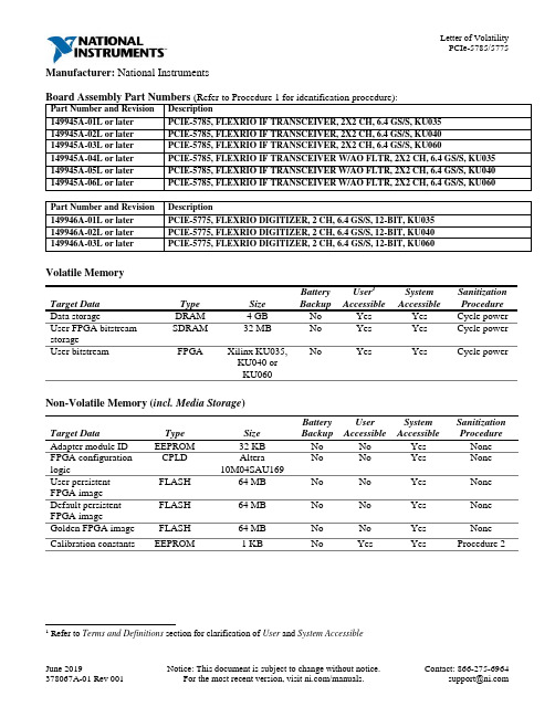
Manufacturer: National InstrumentsBoard Assembly Part Numbers (Refer to Procedure 1 for identification procedure):Part Number and Revision Description149945A-01L or later PCIE-5785, FLEXRIO IF TRANSCEIVER, 2X2 CH, 6.4 GS/S, KU035149945A-02L or later PCIE-5785, FLEXRIO IF TRANSCEIVER, 2X2 CH, 6.4 GS/S, KU040149945A-03L or later PCIE-5785, FLEXRIO IF TRANSCEIVER, 2X2 CH, 6.4 GS/S, KU060149945A-04L or later PCIE-5785, FLEXRIO IF TRANSCEIVER W/AO FLTR, 2X2 CH, 6.4 GS/S, KU035 149945A-05L or later PCIE-5785, FLEXRIO IF TRANSCEIVER W/AO FLTR, 2X2 CH, 6.4 GS/S, KU040 149945A-06L or later PCIE-5785, FLEXRIO IF TRANSCEIVER W/AO FLTR, 2X2 CH, 6.4 GS/S, KU060Part Number and Revision Description149946A-01L or later PCIE-5775, FLEXRIO DIGITIZER, 2 CH, 6.4 GS/S, 12-BIT, KU035149946A-02L or later PCIE-5775, FLEXRIO DIGITIZER, 2 CH, 6.4 GS/S, 12-BIT, KU040149946A-03L or later PCIE-5775, FLEXRIO DIGITIZER, 2 CH, 6.4 GS/S, 12-BIT, KU060Volatile MemoryTarget Data Type Size BatteryBackupUser1AccessibleSystemAccessibleSanitizationProcedureData storage DRAM 4 GB No Yes Yes Cycle power User FPGA bitstreamstorageSDRAM 32 MB No Yes Yes Cycle powerUser bitstream FPGA Xilinx KU035,KU040 orKU060No Yes Yes Cycle power Non-Volatile Memory (incl. Media Storage)Target Data Type Size BatteryBackupUserAccessibleSystemAccessibleSanitizationProcedureAdapter module ID EEPROM 32 KB No No Yes NoneFPGA configuration logic CPLD Altera10M04SAU169No No Yes NoneUser persistentFPGA imageFLASH 64 MB No No Yes NoneDefault persistentFPGA imageFLASH 64 MB No No Yes None Golden FPGA image FLASH 64 MB No No Yes None Calibration constants EEPROM 1 KB No Yes Yes Procedure 21 Refer to Terms and Definitions section for clarification of User and System AccessibleProceduresProcedure 1 – Board Assembly Part Number identification:To determine the Board Assembly Part Number and Revision, refer to the label applied to the surface of your product. The Assembly Part Number should be formatted as “P/N: 146652a-xxL” or “P/N: 149066a-xxL” where “a” is the letter revision of the assembly (e.g. A, B, C…) and “xx” describes the product version.Procedure 2 – Calibration Constants EEPROM:Requirements: LabVIEW 2018 or later and FlexRIO 18.7 or laterThe calibration constants EEPROM can be cleared by using the FlexRIO API to overwrite the memory space with arbitrary values. To clear the storage through LabVIEW, complete the following steps:1.Find and open the example LabVIEW Project “Read-Write Calibration Data”at “C:\<ProgramFiles>\National Instruments\<LabVIEW>\examples\FlexRIO\System Calibration\” (replace<LabVIEW> with version of LabVIEW running on system).a.Alternatively, create a new VI and drop the “Write Calibration Data” VI from the FlexRIO APIpalette.2.Select your FlexRIO device from FPGA Resource dropdown and set Calibration Operation to Write.3.Run VI with Calibration Data set to 0, or other arbitrary value, to clear values in flash memory.4.Repeat Step 3 for entire memory space to clear entire EEPROM memory. Set the Read option for theCalibration Operation to verify data has been cleared or to check sections of memory for otherunintended values.This memory space is also exposed to the C API. Use the following code as reference to clear it:// Open session to the resourceniFlexRIO_OpenSession(resource, bitfile, 0, &session)// Determine calibration storage sizeniFlexRIO_GetAttributeInt32(session, NULL, kFlexRIO_CalibrationStorageSize, &size)// Allocate byte buffer of zeroszeros = calloc(size, 1);// Write zeros to the deviceniFlexRIO_WriteCalibrationData(session, 0, zeros, size)Terms and DefinitionsCycle Power:The process of completely removing power from the device and its components and allowing for adequate discharge. This process includes a complete shutdown of the PC and/or chassis containing the device; a reboot is not sufficient for the completion of this process.Volatile Memory:Requires power to maintain the stored information. When power is removed from this memory, its contents are lost. This type of memory typically contains application specific data such as capture waveforms.Non-Volatile Memory:Power is not required to maintain the stored information. Device retains its contents when power is removed. This type of memory typically contains information necessary to boot, configure, or calibrate the product or may include device power up states.User Accessible:The component is read and/or write addressable such that a user can store arbitrary information to the component from the host using a publicly distributed NI tool, such as a Driver API, the System Configuration API, or MAX. System Accessible:The component is read and/or write addressable from the host without the need to physically alter the product. Clearing:Per NIST Special Publication 800-88 Revision 1, “clearing” is a logical technique to sanitize data in all User Accessible storage locations for protection against simple non-invasive data recovery techniques using the same interface available to the user; typically applied through the standard read and write commands to the storage device.Sanitization:Per NIST Special Publication 800-88 Revision 1, “sanitization” is a process to render access to “Target Data” on the media infeasible for a given level of effort. In this document, clearing is the degree of sanitization described.。
SYSTIMAX GigaSPEED X10D HGS620 屏蔽式接头终端说明书

SYSTIMAX ® Solutions Instruction Sheet 860524180Issue 5, January 2013HGS620 Shielded Outlet Termination Instructions© 2013 CommScope, Inc. All rights reservedPage 1 of 6GeneralThese instructions provide the recommended termination procedure for SYSTIMAX ®GigaSPEED ®X10D HGS620 shielded outlets on F/UTP and S/FTP cables. The outlets are UL approved.Refer to the SYSTIMAX GigaSPEED X10D High Density Shielded Solutions Design and Installation Guidelines for further information.The SYSTIMAX seating tool (760152876) is required for outlet termination. Ordering information is listed below:Material ID Part No.Description760152801 HGS620HGS620 GigaSPEED X10D shielded outlet760152819HGS620-BULK100HGS620 GigaSPEED X10D shielded outlet (100 pack)How to Contact Us• To find out more about CommScope ®products, visit us on the web at / •For technical assistance:-Within the United States, contact your local account representative or technical support at 1-800-344-0223. Outside the United States, contact your local account representative or Authorized Business Partner.-Within the United States, report any missing/damaged parts or any other issues to CommScope Customer Claims at 1-866-539-2795. Outside the United States, contact your local account representative or Authorized Business Partner.Tools Required• Cable jacket scoring tool (such as Xcelite ®2CSKY or JOKARI ®No.1-Cat) • Scissors • Side cutters•SYSTIMAX seating tool.860524180Instruction SheetPage 2 of 6Preparation of F/UTP Cable for Termination1.scoring tool that has fine adjustment settings, such as the Xcelite JOKARI No.1-Cat.2. jacket.3. Trim off clear cellophane wrapping.4. Separate the pairs, cut the flute flush with endof jacket and restore pairs to their original positions. 5. Ensure that foil is pressed tight over thejacket and then wrap drain wire around foil close to end of cable. Do not overlap drain wire when wrapping. 6. Arrange pairs in the order below:• Brown • Blue • Orange • GreenPreparation of S/FTP Cable for Termination1.scoring tool that has fine adjustment settings, such as the Xcelite JOKARI No.1-Cat.2.over cable jacket.Brown pair860524180Issue 5, January 2013Page 3 of 61. termination manager with pair colors oriented to the labels on the termination manager.Important:cable or braided shield on S/FTP cable will manager.2. engage and a click is heard.Note: F/UTP cable shown.Score foil shield1” (25mm)Braided shieldDrain wire860524180Instruction SheetPage 4 of 6Seat and Trim Conductors1. Following the label colors (T568B shown),place conductors directly into termination slots. Seat conductors by pulling tight into slots, then trim pairs flush.Seat Termination Manager on Outlet Body1. Carefully align and insert terminationmanager squarely into outlet body.Note : For correct orientation, the Brown label side faces the 3 notches.2. If outlet will be used in a Keystone compatibleopening, insert Keystone clip on outlet before placing it in seating tool and seating termination manager to outlet body.Note: The clip has three tabs that slide into three notches on outlet body.Orange pairGreen pair860524180Issue 5, January 2013Page 5 of 6For F/UTP cable only, trim excess foil.6. If outlet will be used in a faceplate or boxapplication, attach M-series adapter.Note : The M-series adapter is not allowed where grounding is required.Foil860524180Instruction SheetPage 6 of 6Inspection or Repair of TerminationNote: To enable inspection or repair, the termination manager can be released from the outlet body by inserting a small flat blade screwdriver in slot located on either side of outlet and twisting as shown.To release the termination manager, insert a small flat blade screwdriver between the two halves as shown and twist to disengage the latches.A spudger tool can then be used to remove conductors for repair.Installation in Shallow BoxesIt is acceptable to bend the exiting cable up to 90°, as tight as necessary, in any direction. Use care to ensure the cable shield remains inside the termination manager.Slot。
Logix5000控制器指令执行时间和内存使用参考手册说明书

Reference ManualOriginal InstructionsEstimated Execution Time and Memory Use for Logix5000 Controllers InstructionsCatalog NumbersThis publication provides estimated instruction execution times and memory use information for Logix5000™ controllers in RSLogix 5000® software and Studio 5000 Logix Designer® application projects.Controller/programming software compatibility varies based on controller family and catalog number. For information on compatibility, see the controller documentation.Summary of ChangesThis publication has been revised to add the IMPORTANT table on page 2 indicating that you need to open the PDF file in Adobe® Acrobat® instead of in a web browser.ControlLogix 55701756-L71, 1756-L72, 1756-L73, 1756-L74, 1756-L75GuardLogix 55701756-L72S, 1756-L73S ControlLogix 55601756-L61, 1756-L62, 1756-L63, 1756-L64, 1756-L65GuardLogix 55601756-L61S, 1756-L62S, 1756-L63S CompactLogix 53701769-L16ER-BB1B, 1769-L18ER-BB1B, 1769-L18ERM-BB1B1769-L24ER-QB1B, 1769-L24ER-QBFC1B, 1769-L27ERM-QBFC1B1769-L30ER, 1769-L30ERM, 1769-L30ER-NSE, 1769-L33ER, 1769-L33ERM, 1769-L36ERM1768 CompactLogix 1768-L43, 1768-L451768 Compact GuardLogix 1768-L43S, 1768-L45S1769 CompactLogix 1769-L23E-QB1B, 1769-L23E-QBFC1B, 1769-L23-QBFC1B, 1769-L31, 1769-L32C, 1769-L35CR, 1769-L32E, 1769-L35EDriveLogix 573020D PowerFlex 700S with DriveLogix Estimated instruction execution times are available for the following Logix 5000™ controllers:•ControlLogix® 5580 controllers •GuardLogix® 5580 controllers •CompactLogix™ 5380 controllers •Compact GuardLogix 5380 controllers For more information, see the Estimated Logix 5000 Controller Execution Times Reference Manual, publication LOGIX-RM002.2Rockwell Automation Publication 1756-RM087P-EN-P - July 2020Estimated Execution Time and Memory Use for Logix5000 Controllers Instructions Reference ManualPDF File AttachmentsMicrosoft® Excel® files are attached to this PDF file. The files list execution time and memory use data for Logix5000 controller instructions in RSLogix 5000 software or Logix Designer application projects.The following types of files are available:• A Microsoft Excel file that includes information for all controller families.• A Microsoft Excel files for individual controller families so you can focus on specific controller families.To use the attached files, click the Attachments link, that is, the paper clip icon, and double-click the desired file. IMPORTANT Download the PDF file to your computer and open it with Adobe Acrobat software.If you download the PDF file from Literature Library and open it locally on your computer, you can access, download, and use the Microsoft Excel files.You can open PDF files in some web browsers. However, not all web browsers provide the option to access and open attachments from a PDF file when displaying it.Estimated Execution Time and Memory Use for Logix5000 Controllers Instructions Reference Manual Studio 5000 EnvironmentThe Studio 5000® Engineering and Design Environment combines engineering and design elements into a common environment. The first element in the Studio 5000 environment is the Logix Designer application. The Logix Designer application is the rebranding of RSLogix 5000 software and is the product to program Logix5000 controllers for discrete, process, batch, motion, safety, and drive-based solutions.The Studio 5000 environment is the foundation for the future of Rockwell Automation® engineering design tools and capabilities. It is the oneplace for design engineers to develop all elements of their control system.Rockwell Automation Publication 1756-RM087P-EN-P - July 20203Publication 1756-RM087P-EN-P - July 2020 | Supersedes Publication 1756-RM087O-EN-P-January 2020Copyright © 2020 Rockwell Automation, Inc. All rights reserved. Printed in the U.S.A.Rockwell Otomasyon Ticaret A.Ş. Kar Plaza İş Merkezi E Blok Kat:6 34752 İçerenköy, İstanbul, Tel: +90 (216) 5698400 EEE Yönetmeliğine UygundurAllen-Bradley, CompactLogix, ControlLogix, DriveLogix, expanding human possibility, GuardLogix, Logix5000, Logix 5000, PowerFlex, Rockwell Automation, Rockwell Software, RSLogix 5000, Studio 5000, and Studio 5000 Logix Designer are trademarks of Rockwell Automation, Inc.Acrobat and Adobe are trademarks of Adobe Systems, Inc.Excel and Microsoft are trademarks of Microsoft Corporation.Trademarks not belonging to Rockwell Automation are property of their respective companies.Rockwell Automation maintains current product environmental compliance information on its website at rok.auto/pec .Rockwell Automation SupportUse these resources to access support information.Documentation FeedbackYour comments help us serve your documentation needs better. If you have any suggestions on how to improve our content, complete the form at rok.auto/docfeedback .Technical Support CenterFind help with how-to videos, FAQs, chat, user forums, and product notification updates.rok.auto/support KnowledgebaseAccess Knowledgebase articles.rok.auto/knowledgebase Local Technical Support Phone NumbersLocate the telephone number for your country.rok.auto/phonesupport Literature LibraryFind installation instructions, manuals, brochures, and technical data publications.rok.auto/literature Product Compatibility and Download Center (PCDC)Download firmware, associated files (such as AOP, EDS, and DTM), and access product release notes.rok.auto/pcdc。
研华 OSD Utility 用户手册说明书

User ManualAdvantech OSD UtilityCopyright (3)Features in OSD Utility (4)Limitation (4)General Settings Page (6)Color Settings Page (8)Advanced Settings Page (10)Information Page (12)CopyrightThe documentation and the software included with this product are copyrighted 2021 by Advantech Co., Ltd. All rights are reserved. Advantech Co., Ltd. reserves the right to make improvements in the products described in this manual at any time without notice. No part of this manual may be reproduced, copied, translated or transmitted in any form or by any means without the prior written permission of Advantech Co., Ltd. Information provided in this manual is intended to be accurate and reliable. However, Advantech Co., Ltd. assumes no responsibility for its use, nor for any infringements of the rights of third parties, which may result from its use.Edition 1April 2021Features in OSD UtilityThis section outlines the features that are provided in OSD utility. The utility provides basicOn-Screen Display functions, including general settings, color settings, advanced settings and the information regarding to the utility.LimitationThe utility supports FPM-200 series, including the following products:∙FPM-212∙FPM-215∙FPM-217∙FPM-219The utility only supports the following Windows operating systems:∙Windows 10x86 / x64∙Windows 7x86 / x64Please make sure that .NET Framework package (version 4.6.2 or higher version) is installed in advance, if not, then the following message will be displayed during installation.※WARNING! If the target monitor (or monitors) does not conform to the specifications of both DDC/CI (Display Data Channel / Command Interface) standard and MCCS (Monitor ControlCommand Set), the following error message will be displayed during initialization.Finally, the GUI of the utility will show as below. Please make sure that the specifications are met for the utility to be functional.※WARNING! The host device also requires the appropriate graphic driver for OSD utility to be fully operational; otherwise, the following error message will be displayed during initialization.※WARNING! The utility does not support manipulation to a same monitor over multiple devices at the same time.※WARNING! The utility does not support "Hot Plug Detect". If a new input source is plugged in or an existing source is unplugged during runtime, please restart the utility to get the available input sources again.Note:If the desired input source is not available, the firmware will automatically switch the source to an available source.3.BrightnessControl the level of brightness using scroll bar.4.ContrastControl the level of contrast using scroll bar.5.Restore Factory DefaultsRestore all settings to factory default values, this process takes about 5 seconds to complete, and the following GUI will be displayed during restoring.When exiting the program, the following message box will be displayed to ask user if current settings should be kept or restore the default settings for the monitor (or all monitors ifconnected), click yes to restore the monitor (or monitors) to default settings, click no to keep the current settings for the monitor (or monitors).Color Settings PageThis page provides the following functions, including color temperature selecting, color defaults restoring, red video gain level adjustment, green video gain level adjustment and blue video gain level adjustment.1.Color TemperatureSelect the color temperature for the monitor, ex. 6500K, 9300K, user n (user defined color temperature, n = 1~3) and eye protection mode (reduction of blue video gain).2.Restore Color DefaultsRestore brightness level, contrast level and user-defined RGB colors to factory default values, this process takes about 5 seconds to complete, and the following GUI will be displayed during restoring.3.Red Video GainControl the level of red video gain using scroll bar.Note:This function is only available for user-defined color temperature.4.Green Video GainControl the level of green video gain using scroll bar.Note:This function is only available for user-defined color temperature.5.Blue Video GainControl the level of blue video gain using scroll bar.Note:This function is only available for user-defined color temperature.The following GUI is an example when the user-defined option is not selected for the color temperature setting, making red, green and blue video gains functions disabled.Advanced Settings PageThis page provides the following functions, including auto geometry setup, auto color setup, horizontal position adjustment, vertical position adjustment and clock level adjustment. Note:These functions are only available for analog input source, ex. VGA.1. Auto Geometry SetupAuto adjust the values of horizontal position, vertical position and clock level, this process takes about 5 seconds to complete, and the following GUI will be displayed during setting.2. Auto Color SetupPerform analog auto color setup.3. Horizontal PositionControl the level of horizontal position using scroll bar.4. Vertical PositionControl the level of vertical position using scroll bar.5. ClockControl the level of clock using scroll bar.The following GUI is an example when the selected input source is not an analog type source, making the functions as described above unable to control.Information PageThis page shows the OSD firmware version, MCCS (Monitor Control Command Set) version, utility version and the FPM products that are currently supported.Please verify specifications before quoting. This guide is intended for reference purposes only.All product specifications are subject to change without notice.No part of this publication may be reproduced in any form or by any means, electronic, photocopying, recording or otherwise, without prior written permission of the publisher.All brand and product names are trademarks or registered trademarks of their respective companies.© Advantech Co., Ltd. 2021。
zilog eZ80F91 Mini Ethernet Module Quick Start Gui

An Company Copyright ©2010 by Zilog ®, Inc. All rights IntroductionThis quick qtart guide provides instructions and configuration information for Zilog’s eZ80F91 Mini Ethernet module, eZ80Acclaim!® Modular Development System (MDS) adapter board, and associated components. The eZ80F910100KIT and eZ80F910200KITG modular development kits are covered in this quick start guide.Kit ContentsFor a complete list of material shipped with the eZ80F91 Modular Development Kit (eZ80F910200KITG), refer to eZ80F910200KITG eZ80F91 Series Development Kit Packing List (PAK0015).System RequirementsTable 1 lists the system requirements for running ZDS II.Table 1. ZDS II System RequirementsRecommended ConfigurationMinimum Configuration •PC running MS Windows XP Professional •PC running MS Win2000–SP4/WinXP Professional•Pentium III/500 MHz or higher processor•Pentium II/233 MHz processor •128 MB RAM•96 MB RAM •110 MB hard disk space•25 MB hard disk space (documentation not installed)•Super VGA video adapter•Super VGA video adapter •CD-ROM drive•CD-ROM drive •One or more RS-232communication port •One or more RS-232 communication port ••USB high-speed port •USB high-speed porteZ80F91 Modular Development KitQuick Start Guide QS004611-0810eZ80F91 Modular Development KitInstallation OverviewThe eZ80F91 Mini Ethernet module is preinstalled on the eZ80Acclaim!® MDS adapter board. To set up the development kit, install the ZDS II software. Connect the kit to PC, using the USB Smart Cable or Serial Smart Cable, as appropriate. Connect power to the adapter board. Figure 1 displays the eZ80F91 Modular Development Kit.Previous versions of the development kit used the Serial Smart Cable. Newkits as of June 2006 uses the USB Smart Cable.Follow the steps below to install the cable available with your kit:1.Install the ZDS II software as described in Installing the ZDS II Software and KitDocumentation on page 3.Figure 1.The eZ80F91 Modular Development Kit2.Connect your PC to the eZ80Acclaim! MDS adapter board as follows:(a)If you are using the Serial Smart Cable, follow the instructions in Connecting theSerial Smart Cable to Your Computer on page 3.(b)If you are using the USB Smart Cable (not included with this kit), follow theinstructions in Installing the USB Smart Cable on page 3.3.Connect the 5 V DC power supply to the adapter board.4.Connect the development kit to your PC and run the supplied sample project asdescribed in Running Sample Projects on page 6.For complete details on developing an application for the development kit, refer to Zilog Developer Studio II–eZ80Acclaim!® User Manual (UM0144), and eZ80F91 Modular Development Kit User Manual (UM0170).Note:eZ80F91 Modular Development KitInstalling the ZDS II Software and Kit DocumentationFollow the steps below to install ZDS II and eZ80F91 development kit documentation: 1.Insert the ZDS II CD into the CD-ROM drive. DemoShield launches automatically. IfDemoShield does not launch automatically, open the Windows Explorer, browse to your CD-ROM drive, and double-click launch.exe to launch the installer.2.Click the Install Products button from the main installer menu. From the productinstaller list you can choose to install only ZDS II, or ZDS II and associated documen-tation. You can also copy the documentation directly from your CD-ROM drive to your hard disk using Windows Explorer.Zilog recommends registering your new ZDS II software. By registering Note:ZDS II, you have access to free technical support, software components, andother tools that only registered Zilog customers have. To register online, go to/CustomerPortal/.Connecting the Serial Smart Cable to Your ComputerConnect the Serial Smart Cable 9-pin DB9 serial connector to a COM port on your com-puter.Connecting the Serial Smart Cable to the MDS Adapter Board Attach one end of the six-conductor ribbon cable to the Smart Cable 6-pin DBG connec-tor. See Figure 2 on page 5. Attach the free end of the ribbon cable to the connector on the eZ80Acclaim!® MDS adapter board. The connectors are keyed to ensure proper align-ment.Installing the USB Smart CableYou can install the USB Smart Cable for the following operating systems:Windows Vista-32Follow the steps below to install the USB Smart Cable for Windows Vista-32:1.Connect the USB Smart Cable to the host PC. The Found New Hardware dialog boxis displayed.2.Select Locate and install driver software (recommended). The Driver SoftwareInstallation window is displayed, and then the Found New Hardware-USB Smart Cable dialog box is displayed.eZ80F91 Modular Development Kit3.Select I don’t have the disc. Show me other options.4.Select Browse my computer for driver software (advanced).5.Browse to one of the following driver directory:<ZDS II Installation Directory>\device drivers\USB<ZDS II Installation CD>\Device Drivers\USBThe Windows Security dialog box is displayed.6.Select Install this driver software anyway.7.When the software has been installed, click Closed.Windows XPFollow the steps below to install the USB Smart Cable for Windows XP:1.Connect the USB Smart Cable to the host PC. The Found New Hardware Wizardshould activate automatically.2.In the Wizard, select Install from a list or specific location (Advanced); then clickNext.If the Windows Logo testing dialog appears, select Continue Anyway.Note:3.Select Search for the best driver in these locations and Include this location insearch.4.Browse to one of the following driver directory:<ZDS II Installation Directory>\device drivers\USB<ZDS II Installation CD>\Device Drivers\USB5.Click Next to locate the appropriate driver.6.Click Next and then Click Finish to complete the installation.Windows 2000Follow the steps below to install the USB Smart Cable for Windows 2000:1.Connect the USB Smart Cable to the host PC for the first time.The Found New Hardware Wizard should activate automatically.2.In the Wizard, click Next.3.Select Search for a suitable driver for my device (Recommended); then click Next.4.Select Specify a location; then click Next.eZ80F91 Modular Development Kit5.Browse to the driver directory, one of the following:<ZDS II Installation Directory>\device drivers\USB <ZDS II Installation CD>\Device Drivers\USB6.Click OK , and then click Next after the appropriate driver is found.7.Click Finish to complete the installation.Connecting the USB Smart Cable to the eZ80Acclaim!® MDS Adapter BoardAttach one end of the six-conductor ribbon cable (included) to the USB Smart Cable 6-pin DBG connector. See Figure 2 on page 5. Attach the free end of the ribbon cable to the DBG connector on the eZ80Acclaim! MDS adapter board. Ensure that pin 1 on the ribbon cable (indicated by the dark stripe) is aligned with pin 1 on the target connector.Disconnect or turn OFF the power to the eZ80Acclaim! MDS adapterboard, before connecting or disconnecting the USB Smart Cable.Applying Power to the Development BoardAfter installing the USB Smart Cable, connect the power supply to the development board at connector J7, and then to an electrical outlet. The Green 3.3 V DC LED illuminates indicating that power is supplied to the board.Figure 2.Connecting the Six-Conductor Ribbon Cable to the Serial or USB SmartCableCaution:eZ80F91 Modular Development KitRunning Sample ProjectsAfter installing the ZDS II software and setting up the hardware, you can open and test the sample software projects for the eZ80Acclaim!® product line. Sample projects are located in the following ZDS II sample directories:C:\Program Files\Zilog\ZDSII_eZ80Acclaim!_<version>\samples\ <processor type>_<demo_name>where <processor type> represents the eZ80Acclaim! device that powers the target module and <demo_name> represents the type of sample. (The LedDemo samples are for the legacy eZ80Acclaim! Development Kit that preceded the eZ80F91 Modular Develop-ment Kit).Running the Sample Starter ProjectA sample starter program is provided in the ZDS II CD-ROM. It demonstrates how to write proper code for the eZ80F91 modular development kit. The program writes a few character strings either to RS-232 PortP2 on the eZ80Acclaim! MDS adapter board, or to the Simulated Universal Asynchronous Receiver/Transmitter (UART) Output window (when running the Simulator Debug Tool).Once you have created your own application program, use ZDS II to download that code into the eZ80F91 for testing and debugging.The starter project is written, such that, it defaults to the RS-232 port version. Connect port 2 on the eZ80Acclaim!® MDS adapter board to your PC before running the sample program.Follow the steps below to build and run the sample program for viewing in HyperTerminal on your PC:1.Connect the DB9 RS-232 port on the eZ80Acclaim! MDS adapter board to an openserial port on your PC.2.Open HyperTerminal.3.On the File menu, click New Connection.4.In the Name field, enter a name that describes the connection.5.In the Icon box, click the appropriate icon, and then click OK.6.In the Connect To dialog box, choose the COM port you connected to the RS-232port on the eZ80F91 MDS adapter board in the Connect using drop-down box.7.In the Port Settings dialog box, set the following options:eZ80F91 Modular Development Kit•Bits per second: 57600•Data bits: 8•Parity: None•Stop bits: 1•Flow control: None8.Click OK. HyperTerminal connects to your kit.unch ZDS II by navigating Start→Programs→Zilog ZDS II - eZ80Acclaim!<Version>→ZDS II - eZ80Acclaim! <Version>.10.From the File menu in ZDS II, choose Open Project, and navigate to the followingfile path:c:\Program Files\Zilog\ZDSII_eZ80Acclaim!_<Version>\samples\StarterProject11.Select the starter.zdsproj project within the above file path and click Open. Alist of source files appears in the Workspace panel.12.Double-click the file main.c in the Workspace panel to open the file in the ZDS IIeditor window. Refer to the header of main.c for details about the project.13.Open the Build menu and select Set Active Configuration.14.In the Select Configuration dialog box, select Debug.15.Click OK to close the Select Configuration dialog box.16.From the Project menu in ZDS II, select Settings. The Project Settings dialog boxappears. In the Project Settings dialog box, select the Debugger page.17.In the Debugger page, select eZ80F91ModDevKit_RAM in the Target list.18.In the Debugger page, select SerialSmartCable or USBSmartCable from theDebug Tool drop-down menu.19.Click OK to close the Project Settings dialog box.20.If closing prompts you to rebuild the affected files, click Yes. Otherwise, select Buildfrom the menu bar and click Rebuild All.21.To run the application, select Debug → Go. Until the default settings are changed, thefollowing output is viewed in the Hyperterminal window:Zilog Developers Studioi = 5eZ80F91 Modular Development Kitd = 25f = 1.260000eZ80F91 5 25 1.260000Viewing the Starter Project Output via the ZDS II Cycle-Accurate Simulator (Optional)Follow the steps below to view the output of the starter.zdsproj project in the ZDS II cycle-accurate simulator:1.In ZDS II, open the starter.zdsproj project.2.Select Settings from the Project menu in ZDS II. The Project Settings dialog boxappears. In the Project Settings dialog box, select the Debugger page.3.In the Debugger page, select eZ80F91ModDevKit_RAM in the Target window bychecking the box next to the specific Target Name.4.In the Debugger page, select Simulator from the Debug Tool drop-down menu.5.Click OK to close the Project Settings dialog box.6.If closing prompts you to rebuild the affected files, click Yes. Otherwise, select Buildfrom the menu bar and click Rebuild All.7.When the build is complete, explore the Debug toolbar for the various debugger fea-tures. To connect to the simulator, select Debug→Reset.8.Open the Simulated UART Output window to view the output of the program.Select View→Debug Windows →Simulated UART Output.9.To run the application, select Debug→Go.10.Until the default settings are changed, the following output is viewed in the SimulatedUART Output window:Zilog Developers Studioi = 5d = 25f = 1.260000eZ80F91 5 25 1.260000ing the cycle-accurate simulator, you can view the sample code to study how itworks.You can obtain a sample Zilog ZTP web application and an embedded security Note:SSL application by following the instructions on your kit registration card.eZ80F91 Modular Development KitRelated DocumentationFor complete details on developing an application for the modular development kit, refer to the following documents:•Zilog Developer Studio II–eZ80Acclaim!® User Manual (UM0144)•eZ80F91 Modular Development Kit User Manual (UM0170)•Zilog TCP/IP Software Suite Quick Start Guide (QS0049)•ZTP Network Security Plug-In (SSL) Quick Start Guide (QS0059)•eZ80F91 MCU Product Specification (PS0192)eZ80F91 Modular Development KitDO NOT USE IN LIFE SUPPORTLIFE SUPPORT POLICYZILOG'S PRODUCTS ARE NOT AUTHORIZED FOR USE AS CRITICAL COMPONENTS IN LIFE SUPPORT DEVICES OR SYSTEMS WITHOUT THE EXPRESS PRIOR WRITTEN APPROVAL OF THE PRESIDENT AND GENERAL COUNSEL OF ZILOG CORPORATION.As used hereinLife support devices or systems are devices which (a) are intended for surgical implant into the body, or (b) support or sustain life and whose failure to perform when properly used in accordance with instructions for use provided in the labeling can be reasonably expected to result in a significant injury to the user. A critical component is any component in a life support device or system whose failure to perform can be reasonably expected to cause the failure of the life support device or system or to affect its safety or effectiveness.Document Disclaimer©2010 by Zilog, Inc. All rights reserved. Information in this publication concerning the devices, applications, or technology described is intended to suggest possible uses and may be superseded. ZILOG, INC. DOES NOT ASSUME LIABILITY FOR OR PROVIDE A REPRESENTATION OF ACCURACY OF THE INFORMATION,DEVICES, OR TECHNOLOGY DESCRIBED IN THIS DOCUMENT. ZILOG ALSO D O E S N O T A S S U M E L I A B I L I T Y F O R I N T E L L E C T U A L P R O P E RT Y INFRINGEMENT RELATED IN ANY MANNER TO USE OF INFORMATION,DEVICES, OR TECHNOLOGY DESCRIBED HEREIN OR OTHERWISE. The information contained within this document has been verified according to the general principles of electrical and mechanical engineering.eZ80Acclaim! is a registered trademark of Zilog, Inc. All other product or service names are the property of their respective owners.Warning:。
GA-C621-WD12(-IPMI) Quick Installation Guide 快速安
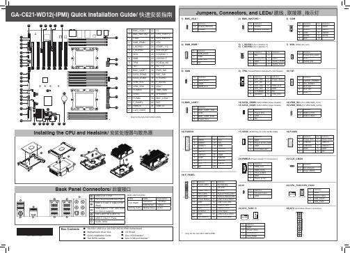
Information in this manual is protected by copyright laws and is the property of GIGABYTE. Changes to the specifications and features in this manual may be made by GIGABYTE without prior notice. No part of this manual may be reproduced, copied, translated, transmitted, or published in any form or by any means without GIGABYTE's prior written permission. For product-related information, check on our website at: https://
19) F_PANEL
1 2 Pin Definition
Pin Definition
1 Power LED+ 2 5V Standby
3-
4 ID LED+
5 Power LED- 6 ID LED-
7 HDD LED+
8 System Status LED+
23 24 9 HDD LED1
10 System Status LED-
Box Contents
55 GA-C621-WD12 or GA-C621-WD12-IPMI motherboard
55 Motherboard driver disk
55 I/O Shield
- 1、下载文档前请自行甄别文档内容的完整性,平台不提供额外的编辑、内容补充、找答案等附加服务。
- 2、"仅部分预览"的文档,不可在线预览部分如存在完整性等问题,可反馈申请退款(可完整预览的文档不适用该条件!)。
- 3、如文档侵犯您的权益,请联系客服反馈,我们会尽快为您处理(人工客服工作时间:9:00-18:30)。
PCS-9250 GIS ECT/EVT
Residual voltage
Hazardous voltage can be present in the DC circuit just after switching off the DC power supply. It takes a few seconds for the voltage to discharge. CAUTION! Earth
Before applying AC voltage and current or the DC power supply to the equipment, check that they conform to the equipment ratings. Printed circuit board
PCS-9250 Gas Insulated Switch (GIS) Electronic Current/Voltage Transformer InstructioPCS-9250 GIS ECT/EVT
Preface
Introduction
Do not touch the exposed terminals of this equipment while the power is on, as the high voltage generated is dangerous
ii
Date: 2011-03-22
PCS-9250 GIS ECT/EVT
Instructions and Warnings
The following indicators and standard definitions are used:
PCS-9250 GIS ECT/EVT
Date: 2011-03-22
i
PCS-9250 GIS ECT/EVT
DANGER! It means that death, severe personal injury, or considerable equipment damage will occur if safety precautions are disregarded. WARNING! It means that death, severe personal, or considerable equipment damage could occur if safety precautions are disregarded. CAUTION! It means that light personal injury or equipment damage may occur if safety precautions are disregarded. This particularly applies to damage to the device and to resulting damage of the protected equipment. WARNING! The firmware may be upgraded to add new features or enhance/modify existing features, please make sure that the version of this manual is compatible with the product in your hand. WARNING! During operation of electrical equipment, certain parts of these devices are under high voltage. Severe personal injury or significant equipment damage could result from improper behavior. Only qualified personnel should work on this equipment or in the vicinity of this equipment. These personnel must be familiar with all warnings and service procedures described in this manual, as well as safety regulations. In particular, the general facility and safety regulations for work with high-voltage equipment must be observed. Noncompliance may result in death, injury, or significant equipment damage. DANGER! Never allow the current transformer (CT) secondary circuit connected to this equipment to be opened while the primary system is live. Opening the CT circuit will produce a dangerously high voltage. WARNING! Exposed terminals
The earthing terminal of the equipment must be securely earthed Operating environment
The equipment must only be used within the range of ambient environment detailed in the specification and in an environment free of abnormal vibration. Ratings
Do not attach and remove printed circuit boards when DC power to the equipment is on, as this may cause the equipment to malfunction. External circuit
Health and Safety
The information in this chapter of the equipment documentation is intended to ensure that equipment is properly installed and handled in order to maintain it in a safe condition. When electrical equipment is in operation, dangerous voltages will be present in certain parts of the equipment. Failure to observe warning notices, incorrect use, or improper use may endanger personnel and equipment and cause personal injury or physical damage. Before working in the terminal strip area, the equipment must be isolated. Proper and safe operation of the equipment depends on appropriate shipping and handling, proper storage, installation and commissioning, and on careful operation, maintenance and servicing. For this reason, only qualified personnel may work on or operate the equipment. Qualified personnel are individuals who: Are familiar with the installation, commissioning, and operation of the equipment and of the system to which it is being connected; Are able to safely perform switching operations in accordance with accepted safety engineering practices and are authorized to energize and de-energize equipment and to isolate, ground, and label it; Are trained in the care and use of safety apparatus in accordance with safety engineering practices; Are trained in emergency procedures (first aid).
This guide and the relevant operating or service manual documentation for the equipment provide full information on safe handling, commissioning and testing of this equipment. Documentation for equipment ordered from NR is dispatched separately from manufactured goods and may not be received at the same time. Therefore, this guide is provided to ensure that printed information normally present on equipment is fully understood by the recipient. Before carrying out any work on the equipment, the user should be familiar with the contents of this manual, and read relevant chapter carefully. This chapter describes the safety precautions recommended when using the equipment. Before installing and using the equipment, this chapter must be thoroughly read and understood.