MAX6303ESA+中文资料
MAX6303中文资料

( ) ARE FOR MAX6302/MAX6304.
* Patents pending
________________________________________________________________ Maxim Integrated Products 1
For free samples & the latest literature: , or phone 1-800-998-8800
MAX6301–MAX6304
________________________Applications
Medical Equipment Intelligent Instruments Portable Equipment Battery-Powered Computers/Controllers Embedded Controllers Critical µP Monitoring Set-Top Boxes Computers
ELECTRICAL CHARACTERISTICS
(VCC = +2V to +5.5V, TA = TMIN to TMAX, unless otherwise noted. Typical values are at VCC = +5V and TA = +25°C.) PARAMETER Operating Voltage Range (Note 1) Supply Current (Note 2) RESET TIMER Reset Input Threshold Voltage Reset Input Hysteresis Reset Input Leakage Current Reset Output Voltage High (MAX6302/MAX6303/MAX6304) VTH VHYST IRESET IN VCC ≥ 4.5V, ISOURCE = 0.8mA VOH VCC = 2V, ISOURCE = 0.4mA MAX6302/MAX6304, VCC = 1.31V, RL = 10kΩ VCC ≥ 4.5V, ISINK = 3.2mA VCC = 2V, ISINK = 1.6mA Reset Output Voltage Low (MAX6301/MAX6303/MAX6304) VOL MAX6301/ MAX6303 VCC = 1V, ISINK = 50µA, TA = 0°C to +70°C VCC = 1.2V, ISINK = 100µA, TA = -40°C to +85°C 63 26 2.8 4.0 5.2 ±1 ±1 VCC - 0.3 0.4 0.4 0.3 0.3 µs µs ms µA V VCC - 0.4 VCC - 0.4 V VRESET IN falling, VCC = 5.0V VRESET IN rising, VCC = 5.0V 1.195 1.220 1.240 20 ±0.01 ±1 1.245 1.265 V mV nA SYMBOL VCC ICC CONDITIONS MAX6301C/MAX6303C MAX6301E/MAX6303E MAX6302/MAX6304 No load MIN 1.00 1.20 1.31 4.0 TYP MAX 5.50 5.50 5.50 7.0 µA V UNITS
MAX6163AESA-T中文资料

General DescriptionThe MAX6161–MAX6168 are precision, low-dropout,micropower voltage references. These three-terminal devices operate with an input voltage range from (V OUT + 200mV) to 12.6V and are available with output volt-age options of 1.25V, 1.8V, 2.048V, 2.5V, 3V, 4.096V,4.5V, and 5V. They feature a proprietary curvature-cor-rection circuit and laser-trimmed thin-film resistors that result in a very low temperature coefficient of 5ppm/°C (max) and an initial accuracy of ±2mV (max).Specifications apply to the extended temperature range (-40°C to +85°C).The MAX6161–MAX6168 typically draw only 100µA of supply current and can source 5mA (4mA for MAX6161) or sink 2mA of load current. Unlike conven-tional shunt-mode (two-terminal) references that waste supply current and require an external resistor, these devices offer a supply current that is virtually indepen-dent of the supply voltage (8µA/V variation) and do not require an external resistor. Additionally, the internally compensated devices do not require an external com-pensation capacitor. Eliminating the external compen-sation capacitor saves valuable board area in space-critical applications. A low-dropout voltage and a supply-independent, ultra-low supply current make these devices ideal for battery-operated, high-perfor-mance, low-voltage systems.The MAX6161–MAX6168 are available in 8-pin SO packages.________________________ApplicationsAnalog-to-Digital Converters (ADCs)Portable Battery-Powered Systems Notebook Computers PDAs, GPS, DMMs Cellular PhonesPrecision +3V/+5V Systems____________________________Features♦±2mV (max) Initial Accuracy♦5ppm/°C (max) Temperature Coefficient ♦5mA Source Current at 0.9mV/mA ♦2mA Sink Current at 2.5mV/mA ♦Stable with 1µF Capacitive Loads ♦No External Capacitor Required ♦100µA (typ) Quiescent Supply Current ♦200mV (max) Dropout at 1mA Load Current ♦Output Voltage Options: 1.25V, 1.8V, 2.048V, 2.5V,3V, 4.096V, 4.5V, 5V19-1650; Rev 3; 8/05MAX6161–MAX6168Precision, Micropower, Low-Dropout, High-Output-Current, SO-8 Voltage References________________________________________________________________Maxim Integrated Products 1___________________Pin Configuration*Insert the code for the desired initial accuracy and temperature coefficient (from the Selector Guide) in the blank to complete the part number.Typical Operating Circuit and Selector Guide appear at end of data sheet.Ordering InformationFor pricing, delivery, and ordering information,please contact Maxim/Dallas Direct!at 1-888-629-4642, or visit Maxim’s website at .M A X 6161–M A X 6168Precision, Micropower, Low-Dropout, High-Output-Current, SO-8 Voltage References 2_______________________________________________________________________________________ABSOLUTE MAXIMUM RATINGSStresses beyond those listed under “Absolute Maximum Ratings” may cause permanent damage to the device. These are stress ratings only, and functional operation of the device at these or any other conditions beyond those indicated in the operational sections of the specifications is not implied. Exposure to absolute maximum rating conditions for extended periods may affect device reliability.Voltages Referenced to GNDIN …………............................................................-0.3 to +13.5V OUT………………........................................-0.3V to (V IN + 0.3V)Output Short-Circuit Duration to GND or IN (V IN ≤6V)...Continuous Output Short-Circuit Duration to GND or IN (V IN > 6V)…...........60sContinuous Power Dissipation (T A = +70°C)8-Pin SO (derate 5.88mW/°C above +70°C)...............471mW Operating Temperature Range ...........................-40°C to +85°C Storage Temperature Range………….…………-65°C to +150°C Lead Temperature (soldering, 10s)……………………….+300°CELECTRICAL CHARACTERISTICS—MAX6161 (V OUT = 1.25V)MAX6161–MAX6168Precision, Micropower, Low-Dropout, High-Output-Current, SO-8 Voltage References_______________________________________________________________________________________3ELECTRICAL CHARACTERISTICS—MAX6168 (V OUT = 1.800V)M A X 6161–M A X 6168Precision, Micropower, Low-Dropout, High-Output-Current, SO-8 Voltage References 4_______________________________________________________________________________________ELECTRICAL CHARACTERISTICS—MAX6162 (V OUT = 2.048V)MAX6161–MAX6168Precision, Micropower, Low-Dropout, High-Output-Current, SO-8 Voltage References_______________________________________________________________________________________5ELECTRICAL CHARACTERISTICS—MAX6166 (V OUT = 2.500V)M A X 6161–M A X 6168Precision, Micropower, Low-Dropout, High-Output-Current, SO-8 Voltage References 6_______________________________________________________________________________________ELECTRICAL CHARACTERISTICS —MAX6163 (V OUT = 3.000V)MAX6161–MAX6168Precision, Micropower, Low-Dropout, High-Output-Current, SO-8 Voltage References_______________________________________________________________________________________7ELECTRICAL CHARACTERISTICS—MAX6164 (V OUT = 4.096V)M A X 6161–M A X 6168Precision, Micropower, Low-Dropout, High-Output-Current, SO-8 Voltage References 8_______________________________________________________________________________________ELECTRICAL CHARACTERISTICS —MAX6167 (V OUT = 4.500V)MAX6161–MAX6168Precision, Micropower, Low-Dropout, High-Output-Current, SO-8 Voltage References_______________________________________________________________________________________9ELECTRICAL CHARACTERISTICS—MAX6165 (V OUT = 5.000V)Note 2:Temperature Coefficient is specified by the “box” method; i.e., the maximum ΔV OUT is divided by the maximum ΔT.Note 3:Thermal Hysteresis is defined as the change in T A = +25°C output voltage before and after temperature cycling of thedevice (from T A = T MIN to T MAX ). Initial measurement at T A = +25°C is followed by temperature cycling the device to T A = +85°C then to T A = -40°C, and another measurement at T A = +25°C is compared to the original measurement at T A = +25°C.Note 4:Dropout voltage is the minimum input voltage at which V OUT changes ≤0.2% from V OUT at V IN = 5.0V (V IN = 5.5V forMAX6165).M A X 6161–M A X 6168Precision, Micropower, Low-Dropout, High-Output-Current, SO-8 Voltage References 10______________________________________________________________________________________Typical Operating Characteristics(V IN = +5V for MAX6161–MAX6168, V IN = +5.5V for MAX6165, I OUT = 0, T A = +25°C, unless otherwise noted.) (Note 5)MAX6161OUTPUT VOLTAGE TEMPERATURE DRIFTTEMPERATURE (°C)O U T P U T V O L T A G E (V )70552540-1010-251.24961.24971.24981.24991.25001.25011.25021.25031.25041.25051.2495-4085MAX6165OUTPUT VOLTAGE TEMPERATURE DRIFTTEMPERATURE (°C)O U T P U T V O L T A G E (V )7055-25-102510404.99854.99904.99955.00005.00055.00105.00155.00204.9980-4085MAX6161LONG-TERM DRIFTM A X 6161/68 t o c 03TIME (hrs)D R I F T (p p m )768192384576-30-20-100102030405060-40960MAX6165LONG-TERM DRIFTM A X 6161/68 t o c 04TIME (hrs)D R I F T (p p m )768192384576-90-80-70-60-50-40-30-20-100-100960-300-200-100010020030024681012MAX6161LINE REGULATIONINPUT VOLTAGE (V)O U T P U T V O L T A G E C H A N G E (μV )-1200-600-800-1000-400-20002005971113MAX6165LINE REGULATIONINPUT VOLTAGE (V)O U T P U T V O L T A G E C H A N G E (μV )-310-1-22345-4-224LOAD CURRENT (mA)O U T P U T V O L T A G E C H A N G E (m V)MAX6161LOAD REGULATION-620-2-44861012-6-2-4246LOAD CURRENT (mA)O U T P U T V O L T A G E C H A N G E (m V )MAX6165LOAD REGULATION0.100.050.200.150.250.30021345MAX6166DROPOUT VOLTAGE vs. LOAD CURRENTLOAD CURRENT (mA)D R O P O U T V O L T A GE (V )MAX6161–MAX6168Output-Current, SO-8 Voltage References______________________________________________________________________________________11Typical Operating Characteristics (continued)(V IN = +5V for MAX6161–MAX6168, V IN = +5.5V for MAX6165, I OUT = 0, T A = +25°C, unless otherwise noted.) (Note 5)00.050.150.100.200.2521345LOAD CURRENT (mA)D R O P O U T V O L T A GE (V )MAX6165DROPOUT VOLTAGE vs. LOAD CURRENTM A X 6161/68 t o c 11FREQUENCY (kHz)P S R R (d B )0-10-20-30-40-50-60-70-80-900.0011101000.010.11000MAX6161POWER-SUPPLY REJECTION RATIOvs. FREQUENCY-70-800.001101000-60-50-40-30-20-100FREQUENCY (kHz)P S R R (d B )0.1MAX6165POWER-SUPPLY REJECTION RATIOvs. FREQUENCYM A X 6161/68 t c 12MAX6161SUPPLY CURRENT vs. SUPPLY VOLTAGESUPPLY VOLTAGE (V)S U P P L Y C U R R E N T (μA )1210864108116124132140148156164172180100214MAX6165SUPPLY CURRENT vs. SUPPLY VOLTAGESUPPLY VOLTAGE (V)S U P P L Y C U R R E N T (μA )1312101178969610210811412012613213814415090514MAX6161SUPPLY CURRENT vs. TEMPERATURETEMPERATURE (°C)S U P P L Y C U R R E N T (μA )603510-15108116124132140148156164172180100-4085MAX6165SUPPLY CURRENT vs. TEMPERATURETEMPERATURE (°C)S U P P L Y C U R R E N T (μA )603510-159610210811412012613213814415090-408500.00110100040206080100140120160180200220M A X 6161/68 t o c 17FREQUENCY (kHz)O U T P U T I M P E D A N C E (Ω)0.1MAX6161OUTPUT IMPEDANCE vs. FREQUENCY1800.00110100040206010080120140160M A X 6161/68 t o c 18FREQUENCY (kHz)O U T P U T I M P E D A N C E (Ω)0.1MAX6165OUTPUT IMPEDANCE vs. FREQUENCYM A X 6161–M A X 6168Output-Current, SO-8 Voltage References 12______________________________________________________________________________________Typical Operating Characteristics (continued)(V IN = +5V for MAX6161–MAX6168, V IN = +5.5V for MAX6165, I OUT = 0, T A = +25°C, unless otherwise noted.) (Note 5)V OUT 10μV/div 1s/div MAX61610.1Hz TO 10Hz OUTPUT NOISEM A X 6161/68 t o c 19V OUT 10μV/div1s/divMAX6165NOISEM A X 6161/68 t o c 20V OUT 500mV/divV IN 5V/div10μs/divMAX6161TURN-ON TRANSIENT(C L = 50pF)M A X 6161/68 t o c 21V OUT 2V/divV IN 5V/div40μs/divMAX6165TURN-ON TRANSIENT(C L = 50pF)M A X 6161/67 t o c 22I OUT 500μA/divV OUTAC-COUPLED 100mV/div400μs/div MAX6161LOAD TRANSIENT(I OUT = ±250μA, V IN = 5.0, C L = 0)+250μA -250μAMAX6161/68 toc23I OUT 500μA/divV OUTAC-COUPLED50mV/div400μs/divMAX6165LOAD TRANSIENT(I OUT = ±250μA, C L = 0, V IN = 5.5V)+250μA -250μAMAX6161/68 toc24MAX6161–MAX6168Output-Current, SO-8 Voltage References______________________________________________________________________________________13I OUT 5mA/divV OUTAC-COUPLED50mV/div400μs/divMAX6165LOAD TRANSIENT(C L = 0, I OUT = ±2mA, V IN = 5.5V)+2mA -2mAMAX6161/68 toc28I OUT 5mA/divV OUTAC-COUPLED 100mV/div 400μs/div MAX6161LOAD TRANSIENT(V IN = 5.0V, C L = 0, I OUT = ±2mA)+2mA-2mAMAX6161/68 toc27I OUT 5mA/divV OUTAC-COUPLED50mV/div400μs/divMAX6161LOAD TRANSIENT(V IN = 5.0V, C L = 1μF, I OUT = ±2mA)+2mA-2mAMAX6161/68 toc29I OUT 5mA/divV OUTAC-COUPLED20mV/div400μs/divMAX6165LOAD TRANSIENT(C L = 1μF, I OUT = ±2mA, V IN = 5.5V)+2mA-2mAMAX6161/68 toc30I OUT 500μA/divV OUTAC-COUPLED10mV/div 400μs/div MAX6161LOAD TRANSIENT(I OUT = ±250μA, V IN = 5.0V, C L = 1μF)+250μA -250μAMAX6161/68 toc25I OUT 500μA/divV OUTAC-COUPLED20mV/div400μs/divMAX6165LOAD TRANSIENT(I OUT = ±250μA, C L = 1μF, V IN = 5.5V)+250μA-250μAMAX6161/68 toc26Typical Operating Characteristics (continued)(V IN = +5V for MAX6161–MAX6168, V IN = +5.5V for MAX6165, I OUT = 0, T A = +25°C, unless otherwise noted.) (Note 5)M A X 6161–M A X 6168Output-Current, SO-8 Voltage References 14______________________________________________________________________________________I OUT 5mA/divV OUTAC-COUPLED50mV/div 400μs/div MAX6161LOAD TRANSIENT(V IN = 5.0V, C L = 1μF, I OUT = ±4mA)+4mA-4mAMAX6161/68 toc33I OUT 5mA/divV OUTAC-COUPLED50mV/div400μs/divMAX6165LOAD TRANSIENT(I OUT = ±5mA, C L = 1μF, V IN = 5.5V)+5mA-5mAMAX6161/68 toc34V IN500mV/divV OUTAC-COUPLED20mV/div 40μs/div MAX6161LINE TRANSIENT(C L = 0)+0.25V-0.25VMAX6161/68 toc35V IN500mV/divV OUTAC-COUPLED20mV/div40μs/divMAX6165LINE TRANSIENT(C L = 0)+0.25V -0.25VMAX6161/68 toc36Note 5:Many of the Typical Operating Characteristics of the MAX6161 family are extremely similar. The extremes of these characteristicsare found in the MAX6161 (1.25V output) and the MAX6165 (5.0V output). The Typical Operating Characteristics of the remain-der of the MAX6161 family typically lie between these two extremes and can be estimated based on their output voltages.Typical Operating Characteristics (continued)(V IN = +5V for MAX6161–MAX6168, V IN = +5.5V for MAX6165, I OUT = 0, T A = +25°C, unless otherwise noted.) (Note 5)I OUT 5mA/divV OUTAC-COUPLED 200mV/div400μs/div MAX6161LOAD TRANSIENT(V IN = 5.0V, C L = 0, I OUT = ±4mA)+4mA-4mAMAX6161/68 toc31I OUT 5mA/divV OUTAC-COUPLED 100mV/div400μs/divMAX6165LOAD TRANSIENT(I OUT = ±5mA, C L = 0, V IN = 5.5V)+5mA-5mAMAX6161/68 toc32MAX6161–MAX6168Output-Current, SO-8 Voltage References______________________________________________________________________________________15Applications InformationInput BypassingF or the best line-transient performance, decouple the input with a 0.1µF ceramic capacitor as shown in the Typical Operating Circuit . Locate the capacitor as close to IN as possible. When transient performance is less important, no capacitor is necessary.Output/Load CapacitanceDevices in the MAX6161 family do not require an output capacitor for frequency stability. In applications where the load or the supply can experience step changes,an output capacitor of at least 0.1µF will reduce the amount of overshoot (undershoot) and improve the cir-cuit’s transient response. Many applications do not require an external capacitor, and the MAX6161 family can offer a significant advantage in applications when board space is critical.Supply CurrentThe quiescent supply current of the series-mode MAX6161 family is typically 100µA and is virtually inde-pendent of the supply voltage, with only an 8µA/V (max) variation with supply voltage. Unlike series refer-ences, shunt-mode references operate with a series resistor connected to the power supply. The quiescent current of a shunt-mode reference is thus a function of the input voltage. Additionally, shunt-mode references have to be biased at the maximum expected load cur-rent, even if the load current is not present at the time.In the MAX6161 family, the load current is drawn from the input voltage only when required, so supply current is not wasted and efficiency is maximized at all input voltages. This improved efficiency reduces power dissi-pation and extends battery life.When the supply voltage is below the minimum speci-fied input voltage (as during turn-on), the devices can draw up to 400µA beyond the nominal supply current.The input voltage source must be capable of providing this current to ensure reliable turn-on.Output Voltage HysteresisOutput voltage hysteresis is the change in the input voltage at T A = +25°C before and after the device is cycled over its entire operating temperature range.Hysteresis is caused by differential package stress appearing across the bandgap core transistors. The typical temperature hysteresis value is 125ppm.Turn-On TimeThese devices typically turn on and settle to within 0.1% of their final value in 50µs to 300µs, depending on the output voltage (see electrical table of part used).The turn-on time can increase up to 1.5ms with the device operating at the minimum dropout voltage and the maximum load.Typical Operating Circuit__________________________Chip Information TRANSISTOR COUNT: 117PROCESS: BiCMOSPin DescriptionPIN NAME FUNCTIONNo Connection. Not internally connected.N.C.1, 3, 5, 7, 82IN Input Voltage GroundGND 46OUTReference OutputM A X 6161–M A X 6168Output-Current, SO-8 Voltage References 16______________________________________________________________________________________Selector GuideMAX6161–MAX6168Maxim cannot assume responsibility f or use of any circuitry other than circuitry entirely embodied in a Maxim product. No circuit patent licenses are implied. Maxim reserves the right to change the circuitry and specifications without notice at any time.Maxim Integrated Products, 120 San Gabriel Drive, Sunnyvale, CA 94086 408-737-7600_____________________17©2005 Maxim Integrated ProductsPrinted USAis a registered trademark of Maxim Integrated Products, Inc.S O I C N .E P SOutput-Current, SO-8 Voltage ReferencesPackage Information(The package drawing(s) in this data sheet may not reflect the most current specifications. For the latest package outline information go to /packages .)。
MAX3490EESA+中文资料
General DescriptionDevices in the MAX3483E family (MAX3483E/MAX3485E/MAX3486E/MAX3488E/MAX3490E/MAX3491E) are ±15kV ESD-protected, +3.3V, low-power transceivers for RS-485 and RS-422 communications. Each device con-tains one driver and one receiver. The MAX3483E and MAX3488E feature slew-rate-limited drivers that minimize EMI and reduce reflections caused by improperly termi-nated cables, allowing error-free data transmission at data rates up to 250kbps. The partially slew-rate-limited MAX3486E transmits up to 2.5Mbps. The MAX3485E,MAX3490E, and MAX3491E transmit at up to 12Mbps.All devices feature enhanced electrostatic discharge (ESD) protection. All transmitter outputs and receiver inputs are protected to ±15kV using IEC 1000-4-2 Air-Gap Discharge, ±8kV using IEC 1000-4-2 Contact Discharge, and ±15kV using the Human Body Model.Drivers are short-circuit current limited and are protect-ed against excessive power dissipation by thermal shutdown circuitry that places the driver outputs into a high-impedance state. The receiver input has a fail-safe feature that guarantees a logic-high output if both inputs are open circuit.The MAX3488E, MAX3490E, and MAX3491E feature full-duplex communication, while the MAX3483E,MAX3485E, and MAX3486E are designed for half-duplex communication.ApplicationsTelecommunicationsIndustrial-Control Local Area Networks Transceivers for EMI-Sensitive Applications Integrated Services Digital Networks Packet SwitchingFeatureso ESD Protection for RS-485 I/O Pins±15kV—Human Body Model±8kV—IEC 1000-4-2, Contact Discharge ±15kV—IEC 1000-4-2, Air-Gap Discharge o Operate from a Single +3.3V Supply—No Charge Pump Required o Interoperable with +5V Logic o Guaranteed 12Mbps Data Rate (MAX3485E/MAX3490E/MAX3491E)o Slew-Rate Limited for Errorless Data Transmission (MAX3483E/MAX3488E) o 2nA Low-Current Shutdown Mode(MAX3483E/MAX3485E/MAX3486E/MAX3491E)o -7V to +12V Common-Mode Input Voltage Range o Full-Duplex and Half-Duplex Versions Available o Industry-Standard 75176 Pinout (MAX3483E/MAX3485E/MAX3486E)o Current-Limiting and Thermal Shutdown for Driver Overload ProtectionMAX3483E/MAX3485E/MAX3486E/MAX3488E/MAX3490E/MAX3491E3.3V-Powered, ±15kV ESD-Protected, 12Mbps and Slew-Rate-Limited T rue RS-485/RS-422 T ransceivers________________________________________________________________Maxim Integrated Products119-1474; Rev 0; 4/99Selector GuideOrdering InformationOrdering Information continued at end of data sheet.For free samples & the latest literature: , or phone 1-800-998-8800.For small orders, phone 1-800-835-8769.M A X 3483E /M A X 3485E /M A X 3486E /M A X 3488E /M A X 3490E /M A X 3491E3.3V-Powered, ±15kV ESD-Protected, 12Mbps and Slew-Rate-Limited T rue RS-485/RS-422 T ransceiversABSOLUTE MAXIMUM RATINGSDC ELECTRICAL CHARACTERISTICS(V = +3.3V ±0.3V, T = T to T , unless otherwise noted. Typical values are at T = +25°C.)Stresses beyond those listed under “Absolute Maximum Ratings” may cause permanent damage to the device. These are stress ratings only, and functional operation of the device at these or any other conditions beyond those indicated in the operational sections of the specifications is not implied. Exposure to absolute maximum rating conditions for extended periods may affect device reliability.Supply Voltage (V CC ).............................................................+7V Control Input Voltage (RE , DE).................................-0.3V to +7V Driver Input Voltage (DI)...........................................-0.3V to +7V Driver Output Voltage (A, B, Y, Z).......................-7.5V to +12.5V Receiver Input Voltage (A, B)..............................-7.5V to +12.5V Receiver Output Voltage (RO)....................-0.3V to (V CC + 0.3V)Continuous Power Dissipation (T A = +70°C)8-Pin SO (derate 5.88mW/°C above +70°C)..................471mW 8-Pin Plastic DIP (derate 9.09mW/°C above +70°C).....727mW14-Pin SO (derate 8.33mW/°C above +70°C)................667mW 14-Pin Plastic DIP (derate 10mW/°C above +70°C)......800mW Operating Temperature RangesMAX34_ _ EC_ _...................................................0°C to +70°C MAX34_ _ EE_ _.................................................-40°C to +85°C Storage Temperature Range.............................-65°C to +150°C Lead Temperature (soldering, 10sec).............................+300°CMAX3483E/MAX3485E/MAX3486E/MAX3488E/MAX3490E/MAX3491E3.3V-Powered, ±15kV ESD-Protected, 12Mbps and Slew-Rate-Limited T rue RS-485/RS-422 T ransceiversDC ELECTRICAL CHARACTERISTICS (continued)(V CC = +3.3V ±0.3V, T A = T MIN to T MAX , unless otherwise noted. Typical values are at T A = +25°C.)DRIVER SWITCHING CHARACTERISTICS—MAX3485E/MAX3490E/MAX3491E(V = +3.3V, T = +25°C.)DRIVER SWITCHING CHARACTERISTICS—MAX3486E(V = +3.3V, T = +25°C.)*MAX3488E and MAX3491E will be compliant to ±8kV per IEC 1000-4-2 Contact Discharge by September 1999.M A X 3483E /M A X 3485E /M A X 3486E /M A X 3488E /M A X 3490E /M A X 3491E3.3V-Powered, ±15kV ESD-Protected, 12Mbps and Slew-Rate-Limited T rue RS-485/RS-422 T ransceivers4_______________________________________________________________________________________DRIVER SWITCHING CHARACTERISTICS—MAX3483E/MAX3488E(V CC = +3.3V, T A = +25°C.)RECEIVER SWITCHING CHARACTERISTICS(V CC = +3.3V, T A = +25°C.)Note 1:∆V OD and ∆V OC are the changes in V OD and V OC , respectively, when the DI input changes state.Note 2:Measured on |t PLH (Y) - t PHL (Y)|and |t PLH (Z) - t PHL (Z)|.Note 3:The transceivers are put into shutdown by bringing RE high and DE low. If the inputs are in this state for less than 80ns, thedevices are guaranteed not to enter shutdown. If the inputs are in this state for at least 300ns, the devices are guaranteed to have entered shutdown. See Low-Power Shutdown Mode section.MAX3483E/MAX3485E/MAX3486E/MAX3488E/MAX3490E/MAX3491E3.3V-Powered, ±15kV ESD-Protected, 12Mbps and Slew-Rate-Limited T rue RS-485/RS-422 T ransceivers_______________________________________________________________________________________5Typical Operating Characteristics(V CC = +3.3V, T A = +25°C, unless otherwise noted.)252015105000.51.01.52.02.53.53.0OUTPUT CURRENT vs.RECEIVER OUTPUT LOW VOLTAGEM A X 3483E -01OUTPUT LOW VOLTAGE (V)O U T P U T C U R R E N T (m A )-20-18-16-14-12-10-8-6-4-2000.51.01.52.02.53.53.0OUTPUT CURRENT vs.RECEIVER OUTPUT HIGH VOLTAGEM A X 3483E -02OUTPUT HIGH VOLTAGE (V)O U T P U T C U R R E N T (m A )3.003.053.103.153.203.253.30-40-20020406010080RECEIVER OUTPUT HIGH VOLTAGEvs. TEMPERATURETEMPERATURE (°C)O U T P U T H I G H V O L T A G E (V )00.10.20.30.40.50.60.70.8-40-2020406010080RECEIVER OUTPUT LOW VOLTAGEvs. TEMPERATURETEMPERATURE (°C)O U T P U T L O W V O L T A G E (V )2505075100125150175024681012OUTPUT CURRENT vs.DRIVER OUTPUT LOW VOLTAGEM A X 3483E -07OUTPUT LOW VOLTAGE (V)O U T P U T C U R R E N T (m A )100908070605040302010000.5 1.0 1.5 2.0 2.5 3.53.0DRIVER OUTPUT CURRENT vs.DIFFERENTIAL OUTPUT VOLTAGEM A X 3483E -05DIFFERENTIAL OUTPUT VOLTAGE (V)O U T P U T C U R R E N T (m A )1.61.71.81.92.02.12.22.32.42.62.5-40-20020406010080DRIVER DIFFERENTIAL OUTPUT VOLTAGE vs. TEMPERATURETEMPERATURE (°C)D I F FE R E N T I A L O U T P U T V O L T A G E (V )-100-80-60-40-20543210-7-6-3-4-5-2-1OUTPUT CURRENT vs.DRIVER OUTPUT HIGH VOLTAGEM A X 3483E -08OUTPUT HIGH VOLTAGE (V)O U T P U T C U R R E N T (m A )M A X 3483E /M A X 3485E /M A X 3486E /M A X 3488E /M A X 3490E /M A X 3491E3.3V-Powered, ±15kV ESD-Protected, 12Mbps and Slew-Rate-Limited T rue RS-485/RS-422 T ransceivers0.80.70.91.01.11.2-40-2020406010080SUPPLY CURRENT vs. TEMPERATURETEMPERATURE (°C)S U P P L Y C U R R E N T (m A )Typical Operating Characteristics (continued)(V CC = +3.3V, T A = +25°C, unless otherwise noted.)0102030405060708010090-40-2020406010080SHUTDOWN CURRENT vs. TEMPERATUREM A X 3483E -10TEMPERATURE (°C)S H U T D O W N C U R R E N T (n A )Pin DescriptionMAX3483E/MAX3485E/MAX3486E/MAX3488E/MAX3490E/MAX3491E3.3V-Powered, ±15kV ESD-Protected, 12Mbps and Slew-Rate-Limited T rue RS-485/RS-422 T ransceivers_______________________________________________________________________________________7Figure 2. MAX3488E/MAX3490E Pin Configuration and Typical Operating CircuitFigure 3. MAX3491E Pin Configuration and Typical Operating CircuitFigure 1. MAX3483E/MAX3485E/MAX3486E Pin Configuration and Typical Operating CircuitM A X 3483E /M A X 3485E /M A X 3486E /M A X 3488E /M A X 3490E /M A X 3491E3.3V-Powered, ±15kV ESD-Protected, 12Mbps and Slew-Rate-Limited T rue RS-485/RS-422 T ransceivers8_______________________________________________________________________________________Figure 4. Driver V OD and V OC Figure 7. Driver Differential Output Delay and Transition TimesFigure 6. Receiver V OH and V OLFigure 5. Driver V OD with Varying Common-Mode VoltageMAX3483E/MAX3485E/MAX3486E/MAX3488E/MAX3490E/MAX3491E3.3V-Powered, ±15kV ESD-Protected, 12Mbps and Slew-Rate-Limited T rue RS-485/RS-422 T ransceivers_______________________________________________________________________________________9Figure 8. Driver Propagation TimesFigure 9. Driver Enable and Disable Times (t PZH , t PSH , t PHZ )Figure 10. Driver Enable and Disable Times (t PZL , t PSL , t PLZ )M A X 3483E /M A X 3485E /M A X 3486E /M A X 3488E /M A X 3490E /M A X 3491E3.3V-Powered, ±15kV ESD-Protected, 12Mbps and Slew-Rate-Limited T rue RS-485/RS-422 T ransceivers10______________________________________________________________________________________Figure 11. Receiver Propagation DelayFigure 12. Receiver Enable and Disable TimesNote 4: The input pulse is supplied by a generator with the following characteristics: f = 250kHz, 50% duty cycle, t r ≤6.0ns, Z O = 50Ω.Note 5: C L includes probe and stray capacitance._____________________Function TablesDevices with Receiver/Driver Enable(MAX3483E/MAX3485E/MAX3486E/MAX3491E)Table 1. Transmitting* B and A outputs are Z and Y, respectively, for full-duplex part (MAX3491E).X = Don’t care; High-Z = High impedanceTable 2. Receiving* DE is a “don’t care” (x) for the full-duplex part (MAX3491E).X = Don’t care; High-Z = High impedanceDevices without Receiver/Driver Enable(MAX3488E/MAX3490E)Table 3. TransmittingTable 4. Receiving___________Applications InformationThe MAX3483E/MAX3485E/MAX3486E/MAX3488E/MAX3490E/MAX3491E are low-power transceivers for RS-485 and RS-422 communications. The MAX3483E and MAX3488E can transmit and receive at data rates up to 250kbps, the MAX3486E at up to 2.5Mbps, and the MAX3485E/MAX3490E/MAX3491E at up to 12Mbps. The MAX3488E/MAX3490E/MAX3491E are full-duplex trans-ceivers, while the MAX3483E/MAX3485E/MAX3486E are half-duplex. Driver Enable (DE) and Receiver Enable (RE ) pins are included on the MAX3483E/MAX3485E/MAX3486E/MAX3491E. When disabled, the driver and receiver outputs are high impedance.Reduced EMI and Reflections (MAX3483E/MAX3486E/MAX3488E)The MAX3483E/MAX3488E are slew-rate limited, mini-mizing EMI and reducing reflections caused by improp-erly terminated cables. Figure 13 shows the driver output waveform of a MAX3485E/MAX3490E/MAX3491E transmitting a 125kHz signal, as well as the Fourier analysis of that waveform. High-frequency harmonics with large amplitudes are evident. Figure 14 shows the same information, but for the slew-rate-limited MAX3483E/MAX3488E transmitting the same signal. The high-frequency harmonics have much lower amplitudes,and the potential for EMI is significantly reduced.Low-Power Shutdown Mode(MAX3483E/MAX3485E/MAX3486E/MAX3491E)A low-power shutdown mode is initiated by bringing both RE high and DE low. The devices will not shut down unless both the driver and receiver are disabled (high impedance). In shutdown, the devices typically draw only 2nA of supply current.For these devices, the t PSH and t PSL enable times assume the part was in the low-power shutdown mode;the t PZH and t PZL enable times assume the receiver or driver was disabled, but the part was not shut down.MAX3483E/MAX3485E/MAX3486E/MAX3488E/MAX3490E/MAX3491E3.3V-Powered, ±15kV ESD-Protected, 12Mbps and Slew-Rate-Limited T rue RS-485/RS-422 T ransceivers______________________________________________________________________________________11INPUTS OUTPUT A, B RO ≥+0.2V 1≤-0.2V 0Inputs Open1INPUT OUTPUTS DI Z Y 101015MHz 500kHz/div 05MHz500kHz/div Figure 13. Driver Output Waveform and FFT Plot of MAX3485E/MAX3490E/MAX3491E Transmitting a 125kHz Signal Figure 14. Driver Output Waveform and FFT Plot of MAX3483E/ MAX3488E Transmitting a 125kHz SignalM A X 3483E /M A X 3485E /M A X 3486E /M A X 3488E /M A X 3490E /M A X 3491E3.3V-Powered, ±15kV ESD-Protected, 12Mbps and Slew-Rate-Limited T rue RS-485/RS-422 T ransceivers12______________________________________________________________________________________Figure 17. MAX3483E/MAX3488E Driver Propagation Delay Figure 19. MAX3483E/MAX3488E System Differential Voltage at 125kHz Driving 4000 Feet of Cable Figure 20. MAX3485E/MAX3490E/MAX3491E System Differential Voltage at 125kHz Driving 4000 Feet of CableDriver-Output Protection Excessive output current and power dissipation caused by faults or by bus contention are prevented by two mechanisms. A foldback current limit on the output stage provides immediate protection against short circuits over the whole common-mode voltage range (see Typical Operating Characteristics). In addition, a thermal shut-down circuit forces the driver outputs into a high-imped-ance state if the die temperature rises excessively.Propagation Delay Figures 15–18 show the typical propagation delays. Skew time is simply the difference between the low-to-high and high-to-low propagation delay. Small driver/receiver skew times help maintain a symmetrical mark-space ratio (50% duty cycle).The receiver skew time, |t PRLH- t PRHL|, is under 10ns (20ns for the MAX3483E/MAX3488E). The driver skew times are 8ns for the MAX3485E/MAX3490E/MAX3491E, 12ns for the MAX3486E, and typically under 50ns for the MAX3483E/MAX3488E.Line Length vs. Data Rate The RS-485/RS-422 standard covers line lengths up to 4000 feet. For line lengths greater than 4000 feet, see Figure 21 for an example of a line repeater.Figures 19 and 20 show the system differential voltage for parts driving 4000 feet of 26AWG twisted-pair wire at 125kHz into 120Ωloads.For faster data rate transmission, please consult the fac-tory.±15kV ESD Protection As with all Maxim devices, ESD-protection structures are incorporated on all pins to protect against electrostatic discharges encountered during handling and assembly. The driver outputs and receiver inputs of the MAX3483E family of devices have extra protection against static electricity. Maxim’s engineers have developed state-of-the-art structures to protect these pins against ESD of ±15kV without damage. The ESD structures withstand high ESD in all states: normal operation, shutdown, and powered down. After an ESD event, Maxim’s E versions keep working without latchup or damage.ESD protection can be tested in various ways; the transmitter outputs and receiver inputs of this product family are characterized for protection to the following limits:1)±15kV using the Human Body Model2)±8kV using the Contact-Discharge method specifiedin IEC 1000-4-23)±15kV using IEC 1000-4-2’s Air-Gap method.ESD Test Conditions ESD performance depends on a variety of conditions. Contact Maxim for a reliability report that documents test setup, test methodology, and test results.Human Body Model Figure 22a shows the Human Body Model and Figure 22b shows the current waveform it generates when dis-charged into a low impedance. This model consists of a 100pF capacitor charged to the ESD voltage of inter-est, which is then discharged into the test device through a 1.5kΩresistor.IEC 1000-4-2 The IEC 1000-4-2 standard covers ESD testing and performance of finished equipment; it does not specifi-cally refer to integrated circuits. The MAX3483E family of devices helps you design equipment that meets Level 4 (the highest level) of IEC 1000-4-2, without the need for additional ESD-protection components.The major difference between tests done using the Human Body Model and IEC 1000-4-2 is higher peak current in IEC 1000-4-2, because series resistance is lower in the IEC 1000-4-2 model. Hence, the ESD with-stand voltage measured to IEC 1000-4-2 is generally lower than that measured using the Human Body Model. Figure 23a shows the IEC 1000-4-2 model, and Figure 23b shows the current waveform for the ±8kV IEC 1000-4-2, Level 4 ESD contact-discharge test.Figure 21. Line Repeater for MAX3488E/MAX3490E/MAX3491EMAX3483E/MAX3485E/MAX3486E/MAX3488E/MAX3490E/MAX3491E3.3V-Powered, ±15kV ESD-Protected, 12Mbps and Slew-Rate-Limited T rue RS-485/RS-422 T ransceivers ______________________________________________________________________________________13M A X 3483E /M A X 3485E /M A X 3486E /M A X 3488E /M A X 3490E /M A X 3491EThe air-gap test involves approaching the device with a charged probe. The contact-discharge method connects the probe to the device before the probe is energized.Machine ModelThe Machine Model for ESD tests all pins using a 200pF storage capacitor and zero discharge resis-tance. Its objective is to emulate the stress caused when I/O pins are contacted by handling equipment during test and assembly. Of course, all pins require this protection, not just RS-485 inputs and outputs.Typical ApplicationsThe MAX3483E/MAX3485E/MAX3486E/MAX3488E/MAX3490E/MAX3491E transceivers are designed for bidirectional data communications on multipoint bus transmission lines. Figures 24 and 25 show typical net-work applications circuits. These parts can also be used as line repeaters, with cable lengths longer than 4000 feet, as shown in Figure 21.To minimize reflections, the line should be terminated at both ends in its characteristic impedance, and stub lengths off the main line should be kept as short as possible. The slew-rate-limited MAX3483E/MAX3488E and the partially slew-rate-limited MAX3486E are more tolerant of imperfect termination.3.3V-Powered, ±15kV ESD-Protected, 12Mbps and Slew-Rate-Limited T rue RS-485/RS-422 T ransceivers14______________________________________________________________________________________Figure 22a. Human Body ESD Test ModelFigure 22b. Human Body Current WaveformFigure 23a. IEC 1000-4-2 ESD Test ModelFigure 23b. IEC 1000-4-2 ESD Generator Current WaveformMAX3483E/MAX3485E/MAX3486E/MAX3488E/MAX3490E/MAX3491E3.3V-Powered, ±15kV ESD-Protected, 12Mbps and Slew-Rate-Limited T rue RS-485/RS-422 T ransceivers______________________________________________________________________________________15Figure 25. MAX3488E/MAX3490E/MAX3491E Full-Duplex RS-485 NetworkFigure 24. MAX3483E/MAX3485E/MAX3486E Typical RS-485 NetworkM A X 3483E /M A X 3485E /M A X 3486E /M A X 3488E /M A X 3490E /M A X 3491E3.3V-Powered, ±15kV ESD-Protected, 12Mbps and Slew-Rate-Limited T rue RS-485/RS-422 T ransceiversTRANSISTOR COUNT: 761Chip InformationOrdering Information (continued)Maxim cannot assume responsibility for use of any circuitry other than circuitry entirely embodied in a Maxim product. No circuit patent licenses are implied. Maxim reserves the right to change the circuitry and specifications without notice at any time.16____________________Maxim Integrated Products, 120 San Gabriel Drive, Sunnyvale, CA 94086 408-737-7600©1999 Maxim Integrated ProductsPrinted USAis a registered trademark of Maxim Integrated Products.。
max680esa芯片参数资料(免费)
The MAX864/MAX865 are also recommended for new designs. The MAX864 operates at up to 200kHz and uses smaller capacitors. The MAX865 comes in the smaller µMAX package.
PIN-PACKAGE 8 Plastic DIP 8 Narrow SO Dice 8 Plastic DIP 8 Narrow SO 8 CERDIP 14 Plastic DIP 14 Plastic DIP
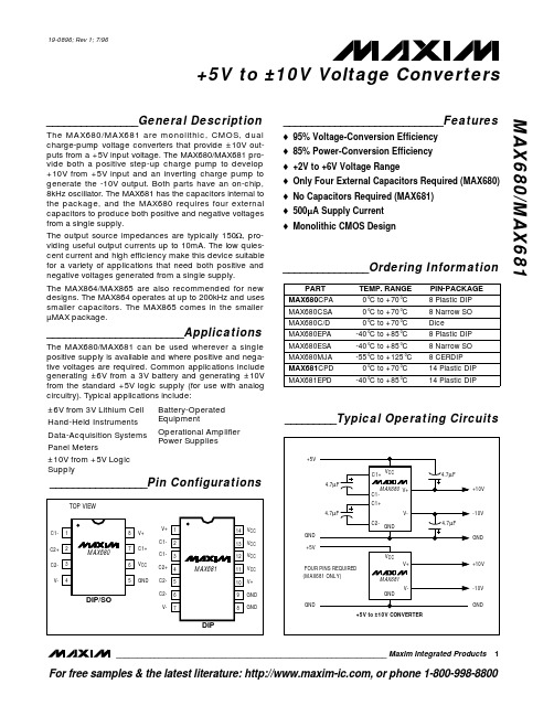
_________Typical Operating Circuits
+5V
4.7µF 4.7µF GND
C1+ VCC
MAX680 C1-
V+
C1+
V-
C2- GND
+5V
FOUR PINS REQUIRED (MAX681 ONLY)
VCC V+
MAX681 V-
GND
GND +5V to ±10V CONVERTER
4.7µF +10V
-10V 4.7µF
GND
+10V
-10V GND
________________________________________________________________ Maxim Integrated Products 1
IL- = 10mA, IL+ = 0mA, V+ = 10V
19-0896; Rev 1; 7/96
+5V to ±10V Voltage Converters
max3485esa中文资料
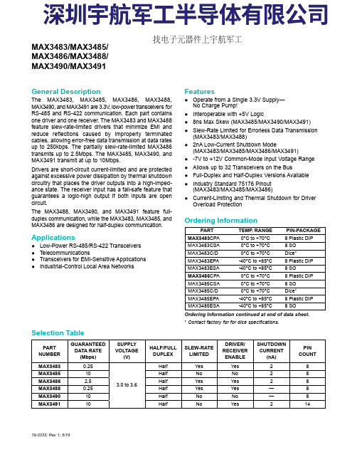
General Description The MAX3483, MAX3485, MAX3486, MAX3488,MAX3490, and MAX3491 are 3.3V , low-power transceivers forRS-485 and RS-422 communication. Each part containsone driver and one receiver. The MAX3483 and MAX3488feature slew-rate-limited drivers that minimize EMI andreduce reflections caused by improperly terminatedcables, allowing error-free data transmission at data ratesup to 250kbps. The partially slew-rate-limited MAX3486transmits up to 2.5Mbps. The MAX3485, MAX3490, andMAX3491 transmit at up to 10Mbps.Drivers are short-circuit current-limited and are protectedagainst excessive power dissipation by thermal shutdowncircuitry that places the driver outputs into a high-imped-ance state. The receiver input has a fail-safe feature thatguarantees a logic-high output if both inputs are opencircuit.The MAX3488, MAX3490, and MAX3491 feature full-duplex communication, while the MAX3483, MAX3485, andMAX3486 are designed for half-duplex communication.Applications ●Low-Power RS-485/RS-422 Transceivers ●Telecommunications ●Transceivers for EMI-Sensitive Applications ●Industrial-Control Local Area NetworksFeatures●Operate from a Single 3.3V Supply—No Charge Pump!●Interoperable with +5V Logic ●8ns Max Skew (MAX3485/MAX3490/MAX3491)●Slew-Rate Limited for Errorless Data Transmission (MAX3483/MAX3488)●2nA Low-Current Shutdown Mode (MAX3483/MAX3485/MAX3486/MAX3491)●-7V to +12V Common-Mode Input Voltage Range ●Allows up to 32 Transceivers on the Bus ●Full-Duplex and Half-Duplex Versions Available ●Industry Standard 75176 Pinout (MAX3483/MAX3485/MAX3486)●Current-Limiting and Thermal Shutdown for Driver Overload Protection 19-0333; Rev 1; 5/19Ordering Information continued at end of data sheet.*Contact factory for for dice specifications.PARTTEMP . RANGE PIN-PACKAGE MAX3483CPA0°C to +70°C 8 Plastic DIP MAX3483CSA0°C to +70°C 8 SO MAX3483C/D0°C to +70°C Dice*MAX3483EPA-40°C to +85°C 8 Plastic DIP MAX3483ESA-40°C to +85°C 8 SO MAX3485CPA0°C to +70°C 8 Plastic DIP MAX3485CSA0°C to +70°C 8 SO MAX3485C/D0°C to +70°C Dice*MAX3485EPA-40°C to +85°C 8 Plastic DIP MAX3485ESA -40°C to +85°C 8 SO PARTNUMBERGUARANTEED DATA RATE (Mbps)SUPPLY VOLTAGE (V)HALF/FULL DUPLEX SLEW-RATE LIMITED DRIVER/RECEIVER ENABLE SHUTDOWN CURRENT (nA)PIN COUNT MAX34830.25 3.0 to 3.6Half Yes Yes 28MAX348510Half No No 28MAX34862.5Half Yes Yes 28MAX34880.25Half Yes Yes —8MAX349010Half No No —8MAX349110Half No Yes 214MAX3483/MAX3485/MAX3486/MAX3488/MAX3490/MAX3491Selection TableOrdering Information找电子元器件上宇航军工Figure 1. MAX3483/MAX3485/MAX3486 Pin Configuration and Typical Operating Circuit Figure 2. MAX3488/MAX3490 Pin Configuration and Typical Operating Circuit Figure 3. MAX3491 Pin Configuration and Typical Operating CircuitMAX3486/MAX3488/MAX3490/MAX3491True RS-485/RS-422 TransceiversFigure 22. MAX3488/MAX3490/MAX3491 Full-Duplex RS-485 NetworkFigure 23. Line Repeater for MAX3488/MAX3490/MAX3491MAX3486/MAX3488/MAX3490/MAX3491True RS-485/RS-422 Transceivers。
amt630a芯片手册
amt630a芯片手册一、简介AMT630A是一款高性能的数字模拟混合芯片,适用于各种需要高精度、低噪声测控的应用场景。
本手册旨在为设计人员提供AMT630A芯片的详细信息,包括功能、引脚定义、性能参数、应用指南等。
二、芯片特性1.高精度:AMT630A具有出色的测控精度,可满足大多数高精度应用的需求。
2.低噪声:在所有频率范围内,噪声水平均较低,有助于提高信号质量。
3.宽工作电压范围:芯片可在5V至12V的工作电压范围内正常工作。
4.模拟通道数量:具有多个模拟输入通道,可满足不同应用场景的需求。
5.数字接口:支持多种数字接口,如SPI、I2C等,方便与微控制器连接。
6.良好的温度性能:在宽广的温度范围内性能稳定,适用于各种工业环境和家用电器。
三、引脚定义以下为AMT630A芯片的引脚排列及功能说明:1.VCC:芯片供电端,接正电压。
2.GND:接地端。
3.ADC_IN:模拟输入端,连接待测信号。
4.CLK:时钟输入端,用于控制芯片采样频率。
5.DATA_OUT:数字输出端,连接微控制器的数据接口。
6.DO:模拟输出端,连接被测对象。
7.RESET:复位端,用于重置芯片内部采样数据。
四、性能参数1.分辨率:最高可达0.001%满量程(FS),取决于输入信号的动态范围。
2.线性度:±0.2FS范围内,输入信号的变化与输出信号的变化保持线性关系。
3.噪声:在所有频率范围内,噪声水平均低于1mV/sqrt(Hz)。
4.工作电源电压范围:5V至12V。
5.工作温度范围:-40℃至+85℃。
五、应用指南1.测量应用:AMT630A适用于各种需要高精度测量的应用场景,如电力监控、环境监测、医疗设备等。
通过连接适当的传感器,可以实现高精度的测量。
2.工业控制:AMT630A可以与微控制器配合使用,实现工业设备的自动化控制和调节。
例如,通过调节温度、压力等参数,实现工业过程的精确控制。
3.家用电器:AMT630A可以应用于各种家用电器中,如空调、洗衣机、冰箱等,实现精确的温度、湿度、压力等参数的测量和控制。
MAX1483ESA+中文资料

元器件交易网
µMAX is a registered trademark of Maxim Integrated products, Inc.
________________________________________________________________ Maxim Integrated Products 1
元器件交易网
19-0367; Rev 1; 5/06
MAX1482/MAX1483
20µA, 1⁄8-Unit-Load, Slew-Rate-Limited RS-485 Transceivers
_______________General Description
The MAX1482 and MAX1483 are low-power transceivers for RS-485 and RS-422 communication. Both feature slew-rate-limited drivers that minimize EMI and reduce reflections caused by improperly terminated cables. Data rates are guaranteed up to 250kbps. The MAX1482/MAX1483 draw only 20µA of supply current. Additionally, they have a low-current shutdown mode that consumes only 0.1µA. Both parts operate from a single +5V supply. Drivers are short-circuit current limited and are protected against excessive power dissipation by thermal shutdown circuitry that places the driver outputs into a high-impedance state. The receiver input has a fail-safe feature that guarantees a logic-high output if the input is open circuit. The MAX1482 is full duplex and the MAX1483 is half duplex. Both parts have a 1⁄8-unit-load input impedance that guarantees up to 256 transceivers on the bus.
MAX1630EAI中文资料

19-0480; Rev 3; 4/97
KIT ATION EVALU LE B A IL A AV
Multi-Output, Low-Noise Power-Supply Controllers for Notebook Computers
____________________________Features
________________General Description
The MAX1630–MAX1635 are buck-topology, step-down, switch-mode, power-supply controllers that generate logic-supply voltages in battery-powered systems. These high-performance, dual/triple-output devices include onboard power-up sequencing, power-good signaling with delay, digital soft-start, secondary winding control, lowdropout circuitry, internal frequency-compensation networks, and automatic bootstrapping. Up to 96% efficiency is achieved through synchronous rectification and Maxim’s proprietary Idle Mode™ control scheme. Efficiency is greater than 80% over a 1000:1 load-current range, which extends battery life in systemsuspend or standby mode. Excellent dynamic response corrects output load transients caused by the latest dynamic-clock CPUs within five 300kHz clock cycles. Strong 1A on-board gate drivers ensure fast external N-channel MOSFET switching. These devices feature a logic-controlled and synchronizable, fixed-frequency, pulse-width-modulation (PWM) operating mode. This reduces noise and RF interference in sensitive mobile communications and pen-entry applications. Asserting the SKIP pin enables fixed-frequency mode, for lowest noise under all load conditions. The MAX1630–MAX1635 include two PWM regulators, adjustable from 2.5V to 5.5V with fixed 5.0V and 3.3V modes. All these devices include secondary feedback regulation, and the MAX1630/MAX1632/MAX1633/ MAX1635 each contain 12V/120mA linear regulators. The MAX1631/MAX1634 include a secondary feedback input (SECFB), plus a control pin (STEER) that selects which PWM (3.3V or 5V) receives the secondary feedback signal. SECFB provides a method for adjusting the secondary winding voltage regulation point with an external resistor divider, and is intended to aid in creating auxiliary voltages other than fixed 12V. The MAX1630/MAX1631/MAX1632 contain internal output overvoltage and undervoltage protection features.
- 1、下载文档前请自行甄别文档内容的完整性,平台不提供额外的编辑、内容补充、找答案等附加服务。
- 2、"仅部分预览"的文档,不可在线预览部分如存在完整性等问题,可反馈申请退款(可完整预览的文档不适用该条件!)。
- 3、如文档侵犯您的权益,请联系客服反馈,我们会尽快为您处理(人工客服工作时间:9:00-18:30)。
_______________General DescriptionThe MAX6301–MAX6304* low-power microprocessor (µP) supervisory circuits provide maximum adjustability for reset and watchdog functions. The reset threshold can be adjusted to any voltage above 1.22V, using external resistors. In addition, the reset and watchdog timeout periods are adjustable using external capaci-tors. A watchdog select pin extends the watchdog time-out period to 500x. The reset function features immunity to power-supply transients.These four devices differ only in the structure of their reset outputs (see the Selector Guide ). The MAX6301–MAX6304are available in the space-saving 8-pin µMAX ®package,as well as 8-pin PDIP and SO packages.ApplicationsMedical Equipment Embedded Controllers Intelligent Instruments Critical µP Monitoring Portable Equipment Set-Top Boxes Battery-Powered Computers Computers/Controllers____________________________Featureso Adjustable Reset Threshold o Adjustable Reset Timeouto Adjustable Watchdog Timeout o 500x Watchdog Timeout Multiplier o 4µA Supply Currento RESET or RESET Output Optionso Push-Pull or Open-Drain Output Options oGuaranteed RESET Asserted At or Above V CC = 1V (MAX6301/MAX6303)o Power-Supply Transient Immunity o Watchdog Function can be Disabled o PDIP/SO/µMAX Packages Available MAX6301–MAX6304+5V , Low-Power µP Supervisory Circuitswith Adjustable Reset/Watchdog________________________________________________________________Maxim Integrated Products 1Typical Operating Circuit19-1078; Rev 2; 3/07Ordering Information continued at end of data sheet.For pricing, delivery, and ordering information,please contact Maxim/Dallas Direct!at 1-888-629-4642, or visit Maxim’s website at .Selector Guide*Patents pendingµMAX is a registered trademark of Maxim Integrated Products, Inc.Specify lead-free by adding the “+” symbol at the end of the part number when ordering.M A X 6301–M A X 6304+5V , Low-Power µP Supervisory Circuits with Adjustable Reset/Watchdog 2_______________________________________________________________________________________ABSOLUTE MAXIMUM RATINGSELECTRICAL CHARACTERISTICSStresses beyond those listed under “Absolute Maximum Ratings” may cause permanent damage to the device. These are stress ratings only, and functional operation of the device at these or any other conditions beyond those indicated in the operational sections of the specifications is not implied. Exposure to absolute maximum rating conditions for extended periods may affect device reliability.V CC....................................................................................-0.3V to +7.0V RESET IN, SWT, SRT..................................-0.3V to (V CC + 0.3V)WDI, WDS..............................................................-0.3V to +7.0V RESET, RESETMAX6301….......................................................-0.3V to +7.0V MAX6302/MAX6303/MAX6304...............-0.3V to (V CC + 0.3V)Input CurrentV CC ...............................................................................±20mA GND..............................................................................±20mA Output CurrentRESET, RESET ..............................................................±20mAContinuous Power Dissipation (T A = +70°C)PDIP (derate 9.09mW/°C above +70°C)......................727mW SO (derate 5.88mW/°C above +70°C).........................471mW µMAX (derate 4.10mW/°C above +70°C)....................330mW Operating Temperature RangeMAX630_C_A......................................................0°C to +70°C MAX630_E_A...................................................-40°C to +85°C Storage Temperature Range.............................-65°C to +160°C Lead Temperature (soldering, 10s).................................+300°CMAX6301–MAX6304+5V , Low-Power µP Supervisory Circuitswith Adjustable Reset/Watchdog_______________________________________________________________________________________310,00000.0010.010.11101001000RESET TIMEOUT PERIODvs. C SRT1C SRT (nF)R E S E T T I M E O U T P E R I O D (m s )10100100010,00000.0010.010.11101001000EXTENDED-MODEWATCHDOG TIMEOUT PERIOD vs. C SWT(WDS = V CC )1C SWT (nF)W A T C H D O G T I M E O U T P E R I O D (s )10100100010,0000.10.0010.010.11101001000NORMAL-MODEWATCHDOG TIMEOUT PERIOD vs. C SWT(WDS = GND)1C SWT (nF)W A T C H D O G T I M E O U T P E R I O D (m s )101001000ELECTRICAL CHARACTERISTICS (continued)Note 2:WDS = V CC , WDI unconnected.Note 3:Precision timing currents of 500nA are present at both the SRT and SWT pins. Timing capacitors connected to these nodesmust have low leakage consistent with these currents to prevent timing errors.Note 4:The sink/source is supplied through a resistor, and is proportional to V CC (Figure 8). At V CC = 2V, it is typically ±24µA.__________________________________________Typical Operating Characteristics(C SWT = C SRT = 1500pF, T A = +25°C, unless otherwise noted.)M A X 6301–M A X 6304+5V , Low-Power µP Supervisory Circuits with Adjustable Reset/Watchdog 4___________________________________________________________________________________________________________________Typical Operating Characteristics (continued)(C SWT = C SRT = 1500pF, T A = +25°C, unless otherwise noted.)4.252.50-4040SUPPLY CURRENT vs. TEMPERATURE3.253.002.754.00TEMPERATURE (°C)S U P P L Y C U R R E N T (µA )80-60-2060201003.753.504.505.004.75 1.220-4040RESET IN THRESHOLD VOLTAGEvs. TEMPERATURE1.218M A X 6301-4 t o c 08TEMPERATURE (°C)R E S E T R E F E R E N C E V O L T A G E (V )080-60-2060201001.2161.2141.2221.2261.224-4040V CCTO RESET DELAYvs. TEMPERATURE (V CC FALLING)68TEMPERATURE (°C)P R O P A G A T I O N D E L A Y (µs )80-60-206020100646056527276RESET AND WATCHDOG TIMEOUT vs. SUPPLY VOLTAGE4.12M A X 6301-4 t o c 10V CC (V)t R P /t W P (m s )235464.084.044.003.964.163.62.66.02.0 4.0SUPPLY CURRENT vs. SUPPLY VOLTAGE2.83.4SUPPLY VOLTAGE (V)S U P P L Y C U R R E N T (µA )3.0 5.01.52.5 4.53.5 5.53.23.03.84.24.0 4.053.80-4040RESET AND NORMAL-MODE WATCHDOG TIMEOUT PERIODvs. TEMPERATURE3.854.00TEMPERATURE (°C)t R P /t W D (m s )080-60-2060201003.953.904.104.204.150200400600100080040RESET THRESHOLD OVERDRIVE (mV)T R A N S I E N T D U R A T I O N (µs )8012030701102060100105090MAXIMUM TRANSIENT DURATION vs. RESET THRESHOLD OVERDRIVE (V RST )MAX6301–MAX6304+5V , Low-Power µP Supervisory Circuitswith Adjustable Reset/Watchdog_______________________________________________________________________________________5Detailed DescriptionReset Function/OutputThe reset output is typically connected to the reset input of a µP. A µP’s reset input starts or restarts the µP in a known state. The MAX6301–MAX6304 µP supervisory circuits provide the reset logic to prevent code-execution errors during power-up, power-down, and brownout conditions (see the Typical Operating Circuit ).For the MAX6301/MAX6303, RESET changes from high to low whenever the monitored voltage (V IN ) drops below the reset threshold voltage (V RST ). RESET remains low as long as V IN is below V RST . Once V IN exceeds V RST , RESET remains low for the reset timeout period, then goes high. When a reset is asserted due to a watchdog timeout condition, RESET stays low for the reset timeout period. Any time reset asserts, the watch-dog timer clears. At the end of the reset timeout period,RESET goes high and the watchdog timer is restarted from zero. If the watchdog timeout period is exceeded again, then RESET goes low again. This cycle contin-ues unless WDI receives a transition.On power-up, once V CC reaches 1V, RESET is guaran-teed to be a logic-low. F or information about applica-tions where V CC is less than 1V, see the Ensuring a Valid RESET /RESET Output Down to V CC = 0V (MAX6303/MAX6304) section. As V CC rises, RESET remains low.When V IN rises above V RST , the reset timer starts and RESET remains low. When the reset timeout period ends, RESET goes high.On power-down, once V IN goes below V RST , RESET goes low and is guaranteed to be low until V CC drops below 1V. F or information about applications where V CC is less than 1V, see the Ensuring a Valid RESET /RESET Output Down to V CC = 0V (MAX6303/MAX6304)section.The MAX6302/MAX6304 active-high RESET output is the inverse of the MAX6301/MAX6303 active-low RESET output, and is guaranteed valid for V CC > 1.31V.Reset ThresholdThese supervisors monitor the voltage on RESET IN.The MAX6301–MAX6304 have an adjustable reset threshold voltage (V RST ) set with an external resistor voltage-divider (Figure 1). Use the following formula to calculate V RST (the point at which the monitored voltagewhere V RST is the desired reset threshold voltage and V TH is the reset input threshold (1.22V). Resistors R1and R2 can have very high values to minimize current consumption. Set R2 to some conveniently high value (1M Ω, for example) and calculate R1 based on the desired reset threshold voltage, using the following formula:Watchdog TimerThe watchdog circuit monitors the µP’s activity. If the µPdoes not toggle the watchdog input (WDI) within t WD (user selected), reset asserts. The internal watchdog timer is cleared by reset, by a transition at WDI (which can detect pulses as short as 30ns), or by a transition at WDS. The watchdog timer remains cleared while reset is asserted; as soon as reset is released, the timer starts counting (Figure 2).The MAX6301–MAX6304 feature two modes of watchdog timer operation: normal mode and extended mode. In normal mode (WDS = GND), the watchdog timeout period is determined by the value of the capacitor con-nected between SWT and ground (see the Selecting the Reset and Watchdog Timeout Capacitor section). In extended mode (WDS = V CC ), the watchdog timeout period is multiplied by 500. For example, in the extended mode, a 1µF capacitor gives a watchdog timeout period of 22 minutes (see the Extended-Mode Watchdog Timeout Period vs. C SWT graph in the Typical Operating Characteristics ).In extended mode, the watchdog function can be disabled by leaving WDI unconnected or by three-stating the driver connected to WDI. In this mode, the watchdog input is internally driven low during the watchdog timeout period, then momentarily pulses high, resetting theM A X 6301–M A X 6304+5V , Low-Power µP Supervisory Circuits with Adjustable Reset/Watchdog 6_______________________________________________________________________________________Figure 1. Calculating the Reset Threshold Voltage (V RST )watchdog counter. When WDI is left unconnected, the watchdog timer is cleared by this internal driver just before the timeout period is reached (the internal driver pulls WDI high at about 94% of t WD ). When WDI is three-stated, the maximum allowable leakage current of the device driving WDI is 10µA.In normal mode (WDS = GND), the watchdog timer cannot be disabled by three-stating WDI. WDI is a high-impedance input in this mode. Do not leave WDI unconnected in normal mode.Applications InformationSelecting the Reset and WatchdogTimeout CapacitorThe reset timeout period is adjustable to accommodate a variety of µP applications. Adjust the reset timeout period (t RS ) by connecting a specific value capacitor (C SRT ) between SRT and ground (Figure 3). Calculate the reset timeout capacitor as follows:C SRT = t RP / 2.67MAX6301–MAX6304+5V , Low-Power µP Supervisory Circuitswith Adjustable Reset/Watchdog_______________________________________________________________________________________7Figure 2a. Watchdog Timing Diagram, WDS = GNDCCM A X 6301–M A X 6304with C SRT in pF and t RP in µs. C SRT must be a low-leak-age (< 10nA) type capacitor. Ceramic is recommended.The watchdog timeout period is adjustable to accom-modate a variety of µP applications. With this feature,the watchdog timeout can be optimized for software execution. The programmer can determine how often the watchdog timer should be serviced. Adjust the watchdog timeout period (t WD ) by connecting a specif-ic value capacitor (C SWT ) between SWT and ground (F igure 3). F or normal-mode operation, calculate the watchdog timeout capacitor as follows:C SWT = t WD / 2.67where C SWT is in pF and t WD is in µs. C SWT must be a low-leakage (< 10nA) type capacitor. Ceramic is recommended.Monitoring Voltages Other than V CCThe Typical Operating Circuit monitors V CC . Voltages other than V CC can easily be monitored, as shown in F igure 4. Calculate V RST as shown in the Reset Threshold section.Wake-Up TimerIn some applications, it is advantageous to put a µP into sleep mode, periodically wake it up to perform checks and/or tasks, then put it back into sleep mode.The MAX6301 family of supervisors can easily accom-modate this technique. Figure 5 illustrates an example using the MAX6302 and an 80C51.In F igure 5, just before the µC puts itself into sleep mode, it pulls WDS high. The µC’s I/O pins maintain their logic levels while in sleep mode and WDS remains high. This places the MAX6302 in extended mode,increasing the watchdog timeout 500 times. When thewatchdog timeout period ends, a reset is applied on the 80C51, waking it up to perform tasks. While the µP is performing tasks, the 80C51 pulls WDS low (select-ing normal mode), and the MAX6302 monitors the µP for hang-ups. When the µP finishes its tasks, it puts itself back into sleep mode, drives WDS high, and starts the cycle over again. This is a power-saving tech-nique, since the µP is operating only part of the time and the MAX6302 has very low quiescent current.Adding a Manual Reset FunctionA manual reset option can easily be implemented by con-necting a normally open momentary switch in parallel with R2 (Figure 6). When the switch is closed, the voltage on RESET IN goes to zero, initiating a reset. When the switch is released, the reset remains asserted for the reset timeout period and then is cleared. The pushbut-ton switch is effectively debounced by the reset timer.+5V , Low-Power µP Supervisory Circuits with Adjustable Reset/Watchdog 8_______________________________________________________________________________________Figure 4. Monitoring Votlages Other than V CCFigure 5. Wake-Up TimerFigure 6. Adding a Manual Reset FunctionInterfacing to µPs with Bidirectional Reset PinsSince RESET is open-drain, the MAX6301 interfaces easily with µPs that have bidirectional reset pins, such as the Motorola 69HC11 (Figure 7). Connecting RESET directly to the µP’s reset pin with a single pullup allows either device to assert reset.Negative-Going V CC TransientsIn addition to issuing a reset to the µP during power-up,power-down, and brownout conditions, these supervisors are relatively immune to short-duration negative-going transients (glitches). The Maximum Transient Duration vs.Reset Threshold Overdrive graph in the Typical Operating Characteristics shows this relationship.The area below the curves of the graph is the region in which these devices typically do not generate a reset pulse. This graph was generated using a negative-going pulse applied to V IN , starting above the actual reset threshold (V RST ) and ending below it by the mag-nitude indicated (reset-threshold overdrive). As the magnitude of the transient increases (farther below the reset threshold), the maximum allowable pulse width decreases. Typically, a V CC transient that goes 100mV below the reset threshold and lasts 50µs or less will not cause a reset pulse to be issued.Watchdog Input CurrentExtended ModeIn extended mode (WDS = V CC ), the WDI input is inter-nally driven through a buffer and series resistor from the watchdog counter (F igure 8). When WDI is left unconnected, the watchdog timer is serviced within the watchdog timeout period by a very brief low-high-low pulse from the counter chain. F or minimum watchdog input current (minimum overall power consumption),leave WDI low for the majority of the watchdog timeout period, pulsing it low-high-low (> 30ns) once within the period to reset the watchdog timer. If instead WDI is externally driven high for the majority of the timeout period, typically 70µA can flow into WDI.Normal ModeIn normal mode (WDS = GND), the internal buffer that drives WDI is disabled. In this mode, WDI is a standard CMOS input and leakage current is typically 100pA,regardless of whether WDI is high or low.Ensuring a Valid RESET /RESET Output Down to V CC = 0V (MAX6303/MAX6304)When V CC falls below 1V, RESET /RESET current sinking (sourcing) capabilities decline drastically. In the case of the MAX6303, high-impedance CMOS-logic inputs connected to RESET can drift to undetermined voltages. This presents no problem in most applica-tions, since most µPs and other circuitry do not operate with V CC below 1V.MAX6301–MAX6304+5V , Low-Power µP Supervisory Circuitswith Adjustable Reset/Watchdog_______________________________________________________________________________________9Figure 7. Interfacing to µPs with Bidirectional Reset I/O Pins Figure 8. Watchdog Input StructureM A X 6301–M A X 6304In those applications where RESET must be valid down to 0V, adding a pulldown resistor between RESET and ground sinks any stray leakage currents, holding RESET low (Figure 9). The value of the pulldown resistor is not critical; 100k Ωis large enough not to load RESET and small enough to pull RESET to ground. For applica-tions using the MAX6304, a 100k Ωpullup resistor between RESET and V CC will hold RESET high when V CC falls below 1V (Figure 10).Watchdog-Software ConsiderationsTo help the watchdog timer monitor software execution more closely, set and reset the watchdog input at differ-ent points in the program, rather than pulsing the watchdog input high-low-high or low-high-low. This technique avoids a stuck loop in which the watchdog timer would continue to be reset within the loop, keeping the watchdog from timing out.F igure 11 shows an example of a flow diagram where the I/O driving the watchdog input is set high at the beginning of the program, set low at the beginning of every subroutine or loop, then set high again when the program returns to the beginning. If the program should hang in any subroutine the problem would quickly be corrected, since the I/O is continually set low and the watchdog timer is allowed to time out, causing a reset or interrupt to be issued. When using extended mode,as described in the Watchdog Input Current section,this scheme does result in higher average WDI input current than does the method of leaving WDI low for the majority of the timeout period and periodically pulsing it low-high-low.Layout ConsiderationsSRT and SWT are precision current sources. When developing the layout for the application, be careful to minimize board capacitance and leakage currents around these pins. Traces connected to these pinsshould be kept as short as possible. Traces carrying high-speed digital signals and traces with large voltage potentials should be routed as far from these pins as possible. Leakage currents and stray capacitance (e.g., a scope probe) at these pins could cause errors in the reset and/or watchdog timeout period. When evaluating these parts, use clean prototype boards to ensure accurate reset and watchdog timeout periods.RESET IN is a high-impedance input that is typically driven by a high-impedance resistor-divider network (e.g., 1M Ωto 10M Ω). Minimize coupling to transient sig-nals by keeping the connections to this input short. Any DC leakage current at RESET IN (e.g., a scope probe)causes errors in the programmed reset threshold. Note that sensitive pins are located on the GND side of the device, away from the digital I/O, to simplify board layout.+5V , Low-Power µP Supervisory Circuits with Adjustable Reset/Watchdog 10______________________________________________________________________________________Figure 9. Ensuring RESET Valid to V CC= 0VFigure 10. Ensuring RESET Valid to V CC= 0VFigure 11. Watchdog Flow DiagramMAX6301–MAX6304+5V , Low-Power µP Supervisory Circuitswith Adjustable Reset/Watchdog______________________________________________________________________________________11Chip InformationTRANSISTOR COUNT: 580Devices are available in both leaded and lead-free packaging.Specify lead-free by adding the “+” symbol at the end of the part number when ordering.Package Information(The package drawing(s) in this data sheet may not reflect the most current specifications. For the latest package outline information go to /packages .)M A X 6301–M A X 6304+5V , Low-Power µP Supervisory Circuits with Adjustable Reset/Watchdog 12______________________________________________________________________________________Maxim cannot assume responsibility for use of any circuitry other than circuitry entirely embodied in a Maxim product. No circuit patent licenses are implied. Maxim reserves the right to change the circuitry and specifications without notice at any time.Maxim Integrated Products, 120 San Gabriel Drive, Sunnyvale, CA 94086 408-737-7600 ____________________13©2007 Maxim Integrated Productsis a registered trademark of Maxim Integrated Products, Inc.MAX6301–MAX6304+5V , Low-Power µP Supervisory Circuitswith Adjustable Reset/WatchdogPackage Information (continued)(The package drawing(s) in this data sheet may not reflect the most current specifications. For the latest package outline information go to /packages .)Revision HistoryPages changed at Rev 2: 1, 13。