T810-800G-RG中文资料
FS108P 8端口ProSafe PoE交换机用户手册说明书
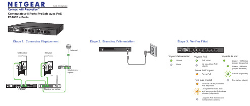
Commutateur 8 Ports ProSafe avec PoEFS108P 4 PortsFS108PAlluméÉteintVoyant d'alimentationActivité (clignotant)Pas de lien (éteint)Liaison 10 Mbits/s (voyant de droite)Voyants de portLiaison 100 Mbits/s (voyant de gauche)Guide d'installationÉtape 2. Branchez l'alimentation Étape 3. Vérifiez l'étatModem en optionÉtape 1. Connectez l'équipementRouteur en optionOrdinateurServeurInternetVoyants PoEMoins de 7W de puissance PoE disponible.PoE max. VoyantLes ports PoE fonctionnent normalement. (éteint)Le voyant PoE MAX était actif au cours des 2 dernières minutes. (clignotant)PoE utiliséNe pas utiliser PoE (éteint)Panne PoEPanne PoE VoyantSeptembre 2012Ce symbole a été apposé conformément à la directive européenne 2002/96 sur la mise au rebut des équipements électriques et électroniques (directive WEEE - Waste Electrical and ElectronicEquipment). En cas de mise au rebut de ce produit dans un État membre de l'Union européenne, il doit être traité et recyclé conformément à cette directive.NETGEAR, le logo NETGEAR et Connect with Innovation sont des marques commerciales et/ou des marques déposées de NETGEAR, Inc. et/ou des filiales de NETGEAR aux Etats-Unis et/ou dans d'autres pays. Les informations sont sujettes à changement sans préavis. Les autres marques et noms de produits sont desmarques commerciales ou des marques déposées de leurs détenteurs respectifs. © NETGEAR, Inc. Tous droits réservés.Pour une utilisation en intérieur dans tous les pays de l'UE et la Suisse.Pour consulter la déclaration de conformité complète, rendez-vous sur le site /app/answers/detail/a_id/11621/.Conditions : NETGEAR se réserve le droit d'apporter des modifications aux produits décrits dans ce document sans préavis afin d'en améliorer la conception, les fonctions opérationnelles et/ou la fiabilité. NETGEAR décline toute responsabilité quant aux conséquences de l'utilisation des produits ou des configurations de circuits décrits dans le présent document.SpécificationsSpécification DescriptionInterface réseauPorts RJ45 Auto-Uplink 10/100 Mbits/s avec PoE activé (ports 1 - 4)Ports RJ45 Auto-Uplink 10/100 Mbits/s (ports 5 - 8)Câble réseau Catégorie 5e (Cat 5e) ou meilleur câble Ethernet Ports8Adaptateur secteur Entrée CC 48V @ 1,25 ABudgetd'alimentation PoE 53W max. tous les ports PoE (1-4), 15,4 W max. par port PoE Poids 0,74 kg (1,7 lb)Dimensions (L × P × H)235 mm x103 mm x 27 mm 9,3 po. x 4,1 po.x 1,1 po.Température de fonctionnement 0-40 ° C (32-104 ° F)Humidité de fonctionnement 10% -90% d'humidité relative, sans condensationConformitéélectromagnétique CE Classe B; FCC Classe B; VCCI Classe B; C-Tick Classe B, CCC Homologations de sécuritéCE/LVD, CCCSupport techniqueAprès l'installation de votre périphérique, notez le numéro de série inscrit surl'étiquette de votre produit. Il vous sera nécessaire pour enregistrer votre produit à l'adresse https:// .Vous devez enregistrer votre produit avant de pouvoir utiliser l'assistancetéléphonique de NETGEAR. NETGEAR vous recommande d'enregistrer votre produit sur le site Web de NETGEAR. Pour obtenir des mises à jour de produits et accéder au support Web, visitez .。
设备接入网关AGS8100使用说明书

设备接入网关AGS8100使用说明书V1.00.002浙江大华技术股份有限公司前言概述本文档主要介绍了AGS8100概述、性能参数、配置和管理设备等。
符号约定符号说明表示有高度潜在危险,如果不能避免,会导致人员伤亡或严重伤害。
表示有中度或低度潜在危险,如果不能避免,可能导致人员轻微或中等伤害。
表示有潜在风险,如果忽视这些文本,可能导致设备损坏、数据丢失、设备性能降低或不可预知的结果。
表示静电敏感的设备。
防静电表示高压危险。
电击防护表示强激光辐射。
激光辐射表示能帮助您解决某个问题或节省您的时间。
表示是正文的附加信息,是对正文的强调和补充。
目录前言 (I)1 概述............................................................................................................................................. - 1 -1.1简介 .................................................................................................................................................... - 1 -1.2产品特色 ............................................................................................................................................ - 1 -1.3组网 .................................................................................................................................................... - 1 -1.4性能参数 ............................................................................................................................................ - 2 -1.5客户端配置要求 ................................................................................................................................ - 2 -2 登录系统..................................................................................................................................... - 4 -3 操作............................................................................................................................................. - 6 -3.1配置参数 ............................................................................................................................................ - 6 -3.2管理设备 ............................................................................................................................................ - 7 -3.2.1 添加GB28181设备.................................................................................................................... - 7 -3.2.2 添加海康设备 ............................................................................................................................. - 8 -3.2.3 添加Onvif设备........................................................................................................................ - 10 -3.2.4 添加General设备..................................................................................................................... - 12 -3.2.5 添加其他厂商、标准协议设备................................................................................................ - 14 -3.2.6 设备查询 ................................................................................................................................... - 14 -3.2.7 设备导出 ................................................................................................................................... - 14 -3.2.8 DSS平台操作............................................................................................................................ - 15 -3.2.9 ONVIF测试工具基本操作 ..................................................................................................... - 17 -4 常见问题................................................................................................................................... - 19 -1概述1.1简介AGS8100是以Windows为架构的硬件化产品,通过将接入的第三方设备的信令转换为大华协议,对外提供一个IP和端口,从而将第三方设备模拟成大华设备,实现平台软件与第三方设备通信。
tewa—800G的光猫说明书

tewa—800G的光猫说明书主板的正面,主要芯片都在这里,处理器、内存和闪存。
CPU是博通BCM68488,双核600MHz。
东芝闪存容量256MB,三星内存大小256MB。
从图中看出闪存是nand,这种闪存一般的编程器无法读写,因此不好刷机折腾。
好在光猫很少有去刷机的。
主板背面基本没有芯片,绝大部分路由器也是如此布局,主要芯片在正面,背面基本无主要器件。
典型双层电路板设计方案,不太复杂的设计单面足以安装主要集成电路。
背面标签型号,2.4G单频无线,默认wifi名称和密码在这里都有。
最高无线速率300Mbps,这是为什么我不建议用光猫自带wifi。
现在路由器基本都是无线双频带放大器,无线传输1200Mbps。
这里一排数个led指示灯,可以据此判断是否工作正常,出现故障可以判断故障原因。
一般使用无需关心。
一般只需要看电源指示灯、注册、光信号,无线等四个要求的2Mbit/s通道。
单E1光传输设备可作为本地网的中继传输设备,尤其适合作为移动通信网基站的光纤终端传输设备以及租用设备。
该设备体积小,重量轻,外型结构紧凑,安装维护方便;传输质量好,运行可靠。
该产品的电接口与PBX 或E1路由器等E1设备相连接,光纤接口适用于多模和单模两种工作环境。
可以和V.35光纤MODEM成对使用,也可以实现(以太网网桥)- - v (E1光Modem)- --(以太网光Modem)的网络结构。
适用于在不同光纤链路上传输带内管理通道,可将传输数据的同一光纤线路用于对本端及远端设备进行监视和控制,且互不干扰;提供SNMP网管。
发射光功率: - -8dBm ~- -15dBm;接收灵敏度:≥- -36dBm;光纤接口: SC、FC型可选;光路码型: 1B1H; 光模块:单纤或双纤可选;适用光纤:单模1310nm或多模光纤可选;传输距离:普通40km (最远可达120km) ; E1接口:标称速率: 2048Kbit/s,容差+50ppm;接口码型: HDB3;接口阻抗: 75Q (非平衡) 120Q (平衡) ;接口类型: BNC头; RJ45水晶头; 2048Kbit/s数字接口电气特性:符合ITU-T G.703建议; 抖动转移特性: 符合ITU-T G.823建议;输入抖动容限:符合ITU-T G.823建议;输出抖动:符合ITU-T G.823建议;。
H3C无线控制器
华三--H3C无线控制器与无线终端设备H3C WX5002无线控制器与中端交换机用插板EWP-WX5002-64-H32端口千兆Combo无线控制器(支持64AP)LIS-WX-32无线控制器license费用-管理32APEWP-WX5004-H3H3C WX5004-4端口千兆Combo无线控制器LSKM2150A150W 交流电源模块LSWM1WCM10H3C S5800 系列-无线功能模块-OSM SlotLSWM1WCM20H3C S58 系列-无线功能模块-接口模块扩展插槽LSPM2150D H3C S5500 150W 直流电源模块H3C WX6103无线控制器与插板模块EWP-WX6103-H3H3C WX6103 无线控制器主机LSQM1WCMB0S7500E 无线控制器业务板模块EWPXM1WCMB0WX6103 无线控制器主控板模块EWPXM1G24XA024端口千兆无线控制器接口板(Combo+Slot插槽) EWPXM1FWA0H3C WX6103-EWPXM1FWA0-无线安全业务板模块LSRM1WCM2A1S9500E 无线控制器业务板H3C WX6103无线控制器配置模块LSQM1AC650H3C PSR650A 交流电源模块,650WLSQM1DC650H3C PSR650D 直流电源模块,650WEWPXM1XP2P H3C WX6103-2端口万兆以太网XFP光接口模块EWPXM1XP1P H3C WX6103-1端口万兆以太网XFP光接口模块LIS-WX-128无线控制器license费用-管理128APH3C WA1208E-主机EWP-WA1208E-GP无线局域网单G模块大功率接入点EWP-WA1208E-GP-FIT无线局域网单G模块大功率接入点-FITH3C无线局域网接入点设备EWP-WA2110-AG-FIT H3C WA2110-AG-无线局域网AG双模单频可管理型接入点-FIT H3C WA2200-主机EWP-WA2210-AG H3C WA2210-AG 无线局域网室内型AG单频双模接入点EWP-WA2220-AG H3C WA2220-AG 无线局域网室内型AG双频双模接入点EWP-WA2220E-AG H3C WA2220E-AG 无线局域网增强型AG双频双模接入点H3C WA2220X-AGP 无线局域网室外型AG双频双模2.4GHz大功EWP-WA2220X-AGP率接入点EWP-WA2220E-AG-T H3C WA2220E-AG-T-车载无线接入点(MR)H3C WA2210X-GE-无线局域网室外增强型802.11b/g单频双模EWP-WA2210X-GE接入点EWP-WA2220X-AGE H3C WA2220X-AGE-无线局域网室外增强型AG双频双模接入点H3C WA2210E-GE,无线局域网增强型802.11b/g单频双模接入EWP-WA2210E-GE点EWP-WB2320X-AGE H3C WB2320X-AGE,无线网桥设备EWP-WA2200-WOU H3C WA2200-无线局域网接入点室外单元模块EWP-WA2210-AG-FIT H3C WA2210-AG 无线局域网室内型AG单频双模接入点-FIT EWP-WA2220-AG-FIT H3C WA2220-AG 无线局域网室内型AG双频双模接入点-FIT EWP-WA2210X-GE-FIT H3C WA2210X-GE-无线局域网室外增强型802.11b/g单频双模接入点-FITEWP-WA2220X-AGP-FITH3C WA2220X-AGP 无线局域网室外型AG双频双模2.4GHz大功率接入点-FITEWP-WA2220X-AGE-FITH3C WA2220X-AGE-无线局域网室外增强型AG双频双模接入点-FITEWP-WA2210E-GE-FITH3C WA2210E-GE-无线局域网增强型802.11b/g单频双模接入点-FITEWP-WA2220E-AG-FIT H3C WA2220E-AG 无线局域网增强型AG双频双模接入点-FIT EWP-WB2320X-AGE-FIT H3C WB2320X-AGE-无线网桥设备-FITEWP-WH2530X-DAG-FIT H3C WH2530X-DAG-无线Mesh设备-FITH3C 无线局域网2.4GHz天线组件-全向&定向天线-802.11b/gTQJ-SA800/2500-3全向天线-824~960/1710~2500MHz-3dBi-垂直-360DEG-50W-0r-N(F)-是TQJ-2400-11-T2全向天线-2400-2500MHz-11dBi-垂直极化-150W-2r-N型母头-自带支架TDJ-SA2400-11-90定向天线-2400~2500MHz-11dBi-90deg-Vertical--0r-300W-with support-N(female)-0.28mTQJ-2400BKF-Y定向天线-2.4~2.483GHz-8.5dBi-80度-垂直极化-50W-N-K-否SL13090A全向天线-2.4~2.5GHz-5dBi-垂直极化-全向-10W-N-K-否TQC-2400CI全向天线-2.4~2.483GHz-5.5dBi-垂直极化-50W-SMA-RP-否TDJ-2400IA(-45)定向天线,2.4~2.5GHz,15dBi,72deg,负45度,100W,N-K,是SL14011A定向天线,2.4~2.5GHz,15±1dBi,30±3deg,垂直极化,100W,N-K,否定向天线,2.4~2.5GHz,10±1dBi,55±3deg,垂直极SL14166A化,100W,N-K,否H3C 无线局域网5.8GHz天线组件-全向&定向天线-802.11a定向天线-5725~5850MHz-17dBi-25deg-垂直TDJ-DBS5800-17-50W-0r-N-Female-自带支架全向天线-5725~5850MHz-12dBi-垂直TQJ-5800-12-T0-12dBi-5W-0r-N(female)-自带支架定向天线-5.725~5.85GHz-29dBi-6度-垂直或水平-100W-N-K-TDJ-5800P6否全向天线-5.725~5.875GHz-5dBi-垂直极化-全向-100W-N-K-SL13089A否定向天线-2.4~2.5&5.15~5.85GHz-12&15dBi-45&20度-垂直极TDJ-2458BKC化-50W-N-K-否定向天线-2.4~2.5&5.15~5.85GHz-2.5&4.5dBi-360度-垂直极TQJ-2458XTJ1化-50W-N-K-否TDJ-5158BKT60-2定向天线-5150-5850MHz-17dBi-60°-垂直极化-50W-N型H3C 无线终端设备发货附件一次电源-0degC-40degC-100V-240V-48V/0.5A-AC电源线可拆FSP025-1AD207A卸CAB-PGND-Pwr-3m外部电源线-机箱PGND-12AWG-3m-(OT6-4)CAB-RF-0.2m-SMA射频电缆-0.2m-(SFF50-3)-(N50直公 to SMA50直母)CAB-RF-1.83m-(2*NSM+RG8/U)射频电缆-1.83m-50ohm-N50直公-(COAX-RG8/U)-N50直公CAB-RF-4.5m-(2*NSM+RG8/U)射频电缆-4.5m-50ohm-N50直公-(COAX-RG8/U)-N50直公CAB-RF-10m-(2*NSM+RG8/U)射频电缆-10m-50ohm-N50直公-(COAX-RG8/U)-N50直公射频电缆-1.83m-50ohm-N50直公-(COAX-RG8/U)-反极性SMA直CAB-RF-1.83m-(N+RG8+SMA)母射频电缆-6.1m-50ohm-N50直公-(COAX-RG8/U)-反极性SMA直CAB-RF-6.1m-(N+RG8+SMA)母射频同轴连接器-N-50ohm-直式-母-配接带N型头的电缆-双阴BNC-RF-N-50-KK转接器,外壳镀三元合金射频同轴连接器-N-50ohm-直式-公-配接N型接头的电缆-双阳N-50JJ转接器信号避雷器-2.5KA@8/20us-300V@Line-Earth-10/100MPOE-MHPoE-RJ45&48VDC JACKMHT6000-N-1天馈避雷器-10KA-20V-2.4~6.0GHz-100W-N-F/N-MSLPS-2504无源分路器-2G/3G-1分4功分器-800~2500MHz-N(F)-SLPS-2503无源分路器-一分三-微带线-800~2500MHz-N/female-无源SL21357B无源分路器-WLAN/3G-1分2功分器-1700~2500MHz-N(F)N-50JR负载-0~8GHz-50ohm-<1.25-2W-N MalePSMA-50KR负载-DC~12.4GHz-50ohm-<=1.25-1W-RSMA FemaleSFP-FE-BX15-U-SM1310SFP模块,-40~85℃,1310nm,15km,LCOP-DLC-10m-S光纤连接器-DLC(GM-8T)-SC*2-单模-7mm-10mEWPA-IM壁挂组件-WA2200OANT-2.4/5.8G H3C WA2200 室外天线安装套件OP-A H3C WA2200,室外电源安装套件EWP-WA2200-WOU H3C WA2200-无线局域网接入点室外单元模块CB-2412/2462MHz合路器-WLAN-2412/2462MHz-NFCAB-AC Pwr-5m-PS4M AC电源线-5m-(PI直公)-(227IEC53 RVV1.0^2(3C))-(PS4公) FSP025-1ADF07B一次电源--30℃-55℃-90VAC-264VAC-48V/0.52AH3C无线控制器用SFP模块SFP-GE-LH40-SM1310光模块-SFP-GE-单模模块-(1310nm,40km,LC)SFP-GE-LH40-SM1550光模块-SFP-GE-单模模块-(1550nm,40km,LC)SFP-GE-LH70-SM1550光模块-SFP-GE-单模模块-(1550nm,70km,LC)SFP-GE-SX-MM850-A光模块-SFP-GE-多模模块-(850nm,0.55km,LC)SFP-GE-LX-SM1310-A光模块-SFP-GE-单模模块-(1310nm,10km,LC)SFP-GE-LX-SM1310-BIDI光模块-SFP千兆BIDI光模块-TX1310/RX1490,10km,LCSFP-GE-LX-SM1490-BIDI光模块-SFP千兆BIDI光模块-TX1490/RX1310,10km,LCXFP-LX-SM1310光模块-XFP-10G-单模模块-(1310nm,10km,LC)XFP-SX-MM850光模块-XFP-10G-多模模块-(850nm,300m,LC)27,000.00XFP-LH40-SM1550-F1XFP万兆光模块(1550nm,40km,LC)H3C 有线无线一体化交换机设备H3C WX3024-PoEP-24端口千兆(4 SFP Combo+Slot插槽+PoE EWP-WX3024-POEP-H3Plus)有线无线一体化交换机LIS-WX-12有线无线一体化交换机license费用-管理12APH3C WX3010-PoEP-10端口千兆(8GE-T+2SFP)有线无线一体化交EWP-WX3010-POEP-H3换机1个WX3010有线无线一体化交换机捆绑10个WA2210-AG-FIT EWP-Z2-1无线局域网室内型AG单频双模接入点1个WX3024有线无线一体化交换机捆绑10个WA2210-AG-FIT EWP-Z2-2无线局域网室内型AG单频双模接入点3个WX3024有线无线一体化交换机捆绑10个WA2210-AG-FIT EWP-Z2-3无线局域网室内型AG单频双模接入点H3C WX3008-PoEP-8端口千兆(8GE-T+PoE Plus)有线无线一体EWP-WX3008-POEP-H3化交换机H3C 有线无线一体化交换机选配模块自带一个FLATPACK 1500电源模块和5根电缆的RPS冗余电源AC-RPS1000-A3(AC-RPS1000-A3,H3C面板),2个槽位可插2个电源模块CAB-RPS PoE-2m-JD5RPS电源线-2.0m-(大插头)-(SJTW2芯12AWG黑)-(大插头) LS5M1XP1PB H3C S5100EI 单端口万兆以太网光接口板(XFP)LS5-FL-B安装弯角组件H3C WA2600-主机H3C WA2610E-AGN 802.11n无线局域网增强型2.4/5GHz单频双EWP-WA2610E-AGN-FIT模接入点-FITH3C WA2620E-AGN 802.11n无线局域网增强型2.4&5GHz双频双EWP-WA2620E-AGN-FIT模接入点-FITH3C WA2610E-AGN 802.11n无线局域网增强型2.4/5GHz单频双EWP-WA2610E-AGN模接入点H3C WA2620E-AGN 802.11n无线局域网增强型2.4&5GHz双频双EWP-WA2620E-AGN模接入点H3C WA2620-AGN 802.11n无线局域网室内型2.4/5GH双频接入EWP-WA2620-AGN点H3C WA2620-AGN 802.11n无线局域网室内型2.4/5GH双频接入EWP-WA2620-AGN-FIT点-FITH3C WA2612-AGN 802.11n无线局域网室内型2.4/5GHz单频接EWP-WA2612-AGN-FIT入点-FITH3C WA2612-AGN 802.11n无线局域网室内型2.4/5GHz单频接EWP-WA2612-AGN入点EWP-WA2610-AGN-FITH3C WA2610-AGN 802.11n无线局域网室内型2.4/5GHz单频接入点-FITEWP-WA2610-AGNH3C WA2610-AGN 802.11n无线局域网室内型2.4/5GHz单频接入点H3C WA2600-天线TQJ-2458MIC×6全向天线-2.4G~2.5GHz,5.15G~5.85GHz-2.5dBi@2.4G,4.5dBi@5G-全向-50W-RPSMA-吸顶安装内置6天线TQJ-2458MIK×3全向天线-2.4G~2.483GHz,5.15G~5.85GHz-2.5dBi@2.4G,4dBi@5G-全向-50W-RPSMA-吸顶安装内置3天线H3C WA2600-发货附件POE-3信号避雷器-3KA@8/20us-350V@Line-Ground-33.6W-1000MPoE-RJ45&48VDC JACKH3C 11n无线网卡EWP-WN612H3C WN612-11n 双频USB无线网卡无线控制器选配电源线CAB-DC Pwr-5m直流电源线-5m-6mm^2-(2*OT6-4)-(227IEC02-6^2蓝+227IEC02-6^2黑)-(2*OT6-6)CAB-DC Pwr-10m直流电源线-10m-10mm^2-(2*OT10-4)-(227IEC02-10^2蓝+227IEC02-10^2黑)-(2*OT10-6)CAB-DC Pwr-20m-2*(OT+T6)外部直流电源线-20m-5.3mm^2-蓝/黑-(2*OT6-4)-(10UL10455蓝+10UL10455黑)-(2*T6^2B)。
NETGEAR 非网管交换机操作指南说明书
注:产品外观因型号而异。
第 2 步:连接到电源并开机。
第 1步:连接设备。
注:电源适配器因地区而异。
计算机因特网第 3 步:检查状态。
电源 LED端口 LED通电以太网连接未通电活动(闪烁)无连接(熄灭)技术支持感谢您购买此 NETGEAR 设备。
安装设备后,请找到产品标签上的序列号并使用它在https://上注册产品。
只有在注册产品后,才能使用 NETGEAR 电话支持。
NETGEAR 建议通过 NETGEAR网站注册产品。
如需产品更新和网络支持,请访问 。
NETGEAR 建议您只使用 NETGEAR 官方支持资源。
您可以在以下网站上找到多种语言的安装指南: 。
有关产品规格的信息,请参阅产品页面或通过以下网站下载数据表: 。
如需最新的欧盟符合性声明,请访问/app/answers/detail/a_id/11621/ 。
有关法规遵从性信息,请访问/about/regulatory/ 。
连接电源之前,请查阅合规性文件。
警告:出于安全考虑,务必仅使用随附产品销售的电源适配器。
如果您不确定要使用哪种电源适配器,请与 NETGEAR 技术支持联系。
支持热线:4008303815中文技术支持站点:网件社区:技术规格百兆和千兆非网管交换机200 和 300 系列200 系列:• 8 口千兆交换机 GS208300 系列:• 8 口百兆交换机 FS308• 8 口千兆交换机 GS3082016 年 7 月有限保修产品注册感谢您选择NETGEAR产品。
如果您想注册您的产品、获取免费支持期(可以于购买产品后的 90 天内通过电话获得基础技术支持)以及查看通用的产品信息和文档,请浏览:https:///registration/login.aspx敬请保管好您产品的有效购买凭证。
本保修声明涵盖的产品NETGEAR 通过本保修声明赋予消费者的权益是对消费者在与商品和服务保修相关的中国法律项下所享有的权利和救济的补充(如果其范围超过消费者在中国法律项下的权利和救济)。
美国网件S8000游戏 高级8端口千兆以太网GS808E交换机用户手册说明书

Nighthawk S8000Gaming&Streaming Advanced8-Port Gigabit Ethernet SwitchModel GS808ENETGEAR, Inc. December 2018350 E. Plumeria Drive202-11732-06San Jose, CA 95134, USASupport Thank you for purchasing this NETGEAR product.You can visit https:///support/to register your product,get help,access the latest downloads and user manuals,and join our community.We recommend that you use only official NETGEAR support resources.Compliance and Conformity For regulatory compliance information including the EU Declaration of Conformity,visit https:///about/regulatory/.See the regulatory compliance document before connecting the power supply.Do not use this device outdoors.If you connect cables or devices that are outdoors to this device,see /000057103for safety and warranty information.Trademarks ©NETGEAR,Inc.,NETGEAR,and the NETGEAR Logo are trademarks of NETGEAR,Inc.Any non-NETGEAR trademarks are used for reference purposes only.Revision HistoryComments Publish Date Publication PartNumberPublished the manual in a new format.Changed Methods to Discover or Access the Switch on page 17.December 2018202-11732-06Added Safety Instructions and Warnings on page 11.Added Change the Language of the Local Browser Interface on page 25.Added the chapter Use VLANS for Traffic Segmentation on page 45.Added Enable a Link Aggregation Group on page 74.Added Enable a VLAN for IGMP Snooping on page 76.Added Control Management Access to the Switch on page 88.Added Change or Lift Access Restrictions to the Switch on page 89.Added Manage the DoS Prevention Mode on page 90.Removed the screen shots.Made multiple minor changes and adjustment to reflect changes in thelocal browser interfaceAugust 2018202-11732-05Added Access the Switch From a Mac or Windows-Based Computer Usingthe NETGEAR Switch Discovery Tool on page 19.Removed information about accessing a switch from a Mac using a Firefoxplug-in.December 2017202-11732-04Added Methods to Discover or Access the Switch on page 17.Added information about accessing a switch from a Mac using a Firefoxplug-in.Added Use the NETGEAR Insight App to Access the Switch on page 24.Added information about the NETGEAR Switch Discovery Tool.November 2017202-11732-03(Continued)Comments Publish Date Publication PartNumberChanged Apply the Gaming Preset Mode on page 29.Changed Apply the Media Streaming Preset Mode on page 30.Changed Apply the Standard Preset Mode on page 31.Changed Use Port-Based Quality of Service and Set Port Priorities on page35.Added Set the Priority for a Port on page 40.Changed Set Up Static Link Aggregation on page 72.Changed Manage IGMPv3IP Header Validation on page 77.Added Use the RESET Button to Renew the DHCP IP Address or Reenable DHCP on page 88.Updated multiple figures and made minor changes to many other sections.June 2017202-11732-02First publication.March 2017202-11732-01ContentsChapter1Hardware Overview of the SwitchRelated Documentation (9)Switch Package Contents (9)Status LEDs (9)Back Panel (10)Switch Label (11)Safety Instructions and Warnings (11)Chapter2Install and Access the Switch in Your NetworkSet Up the Switch in Your Network and Power On the Switch (16)Methods to Discover or Access the Switch (17)Access the Switch and Discover the IP Address of the Switch (17)Access the Switch From a Windows-Based Computer (17)Access the Switch From a Mac Using Bonjour (18)Access the Switch From a Mac or Windows-Based ComputerUsing the NETGEAR Switch Discovery Tool (19)Set Up a Fixed IP Address for the Switch (21)Set Up a Fixed IP Address for the Switch Through a NetworkConnection (21)Set Up a Fixed IP Address for the Switch by Connecting Directlyto the Switch Off-Network (22)Use the NETGEAR Insight App to Access the Switch (24)Change the Language of the Local Browser Interface (25)Change the Switch Password (26)Register the Switch (26)Chapter3Optimize the Switch PerformanceApply a Performance Preset Mode (29)Apply the Gaming Preset Mode (29)Apply the Media Streaming Preset Mode (30)Apply the Standard Preset Mode (31)Manage Custom Performance Preset Modes (32)Save Your Quality of Service Settings as a Custom PresetMode (32)Rename a Custom Preset Mode (33)Delete a Custom Preset Mode (34)Manually Set the Quality of Service Mode and Port Rate Limits (34)Use Port-Based Quality of Service and Set Port Priorities (35)Use802.1P/DSCP Quality of Service (37)Manage Broadcast Filtering and Set Port Storm Control RateLimits (38)Manage Individual Port Settings (39)Set Rate Limits for a Port (39)Set the Priority for a Port (40)Manage Flow Control for a Port (41)Change the Speed for a Port or Disable a Port (42)Add or Change the Name Label for a Port (44)Chapter4Use VLANS for Traffic SegmentationVLAN Overview (46)Activate the Basic Port-Based VLAN Mode and Assign VLANs (47)Manage Advanced Port-Based VLANs (48)Activate the Advanced Port-Based VLAN Mode (48)Create an Advanced Port-Based VLAN (49)Change an Advanced Port-Based VLAN (50)Delete an Advanced Port-Based VLAN (52)Manage Basic802.1Q VLANs (52)Activate the Basic802.1Q VLAN Mode (53)Create a Basic802.1Q VLAN and Assign Ports as Members (54)Assign the Port Mode in a Basic802.1Q VLAN Configuration.55 Change a Basic802.1Q VLAN (57)Delete a Basic802.1Q VLAN (58)Manage Advanced802.1Q VLANs (58)Activate the Advanced802.1Q VLAN Mode (59)Create an Advanced802.1Q VLAN (60)Change an Advanced802.1Q VLAN (62)Specify a Port PVID for an Advanced802.1Q VLAN (63)Set an Existing Advanced802.1Q VLAN as the Voice VLAN and Adjust the CoS Value (64)Change the OUI Table for the Voice VLAN (65)Delete an Advanced802.1Q VLAN (67)Deactivate a Port-Based or802.1Q VLAN Mode and Delete All VLANs (67)Chapter5Manage the Switch in Your NetworkManage Switch Discovery Protocols (70)Manage Universal Plug and Play (70)Manage Bonjour (71)Manage NETGEAR Switch Discovery Protocol (71)Set Up Static Link Aggregation (72)Set Up a Link Aggregation Group (73)Make a Link Aggregation Connection (74)Enable a Link Aggregation Group (74)Manage Multicast (75)Manage IGMP Snooping (75)Enable a VLAN for IGMP Snooping (76)Manage Blocking of Unknown Multicast Addresses (77)Manage IGMPv3IP Header Validation (77)Set Up a Static Router Port for IGMP Snooping (78)Change the IP Address of the Switch (79)Reenable the DHCP Client of the Switch (80)Chapter6Maintain and Monitor the SwitchManually Check for New Switch Firmware and Update theSwitch (83)Manage the Configuration File (84)Back Up the Switch Configuration (84)Restore the Switch Configuration (85)Return the Switch to Its Factory Default Settings (86)Use the RESET Button to Reset the Switch (86)Use the Local Browser Interface to Reset the Switch (87)Use the RESET Button to Renew the DHCP IP Address or Reenable DHCP (88)Control Management Access to the Switch (88)Change or Lift Access Restrictions to the Switch (89)Manage the DoS Prevention Mode (90)Manage the Power Saving Mode (91)Control the Port LEDs (92)Control the Power LED (93)Change the Switch Device Name (93)View System Information (94)View Switch Connections (94)View the Status of a Port (95)Chapter7Diagnostics and TroubleshootingTest a Cable Connection (97)Reboot the Switch From the Local Browser Interface (98)Detect a Network Loop (98)Resolve a Subnet Conflict to Access the Switch (99)Appendix A Factory Default Settings and Technical Specifications Factory Default Settings (101)Technical Specifications (102)Appendix B Additional Switch Discovery and Access Information Access the Switch From Any Computer (105)1Hardware Overview of the Switch The NETGEAR Nighthawk®S8000Gaming&Streaming Advanced8-Port Gigabit Ethernet Switch(GS808E),in this manual referred to as the switch,provides high-performance switching for the home for multiplayer,online,or VR gaming and4K resolution HD and UHD(ultra-high-definition)television media streaming.With one click you can optimize settings for gaming,media steaming,and standard networking,but you can also manually optimize Quality of Service(QoS)and set up prioritization and rate limiting for individual ports.The switch supports IGMP snooping for multicast operation and link aggregation for a connection of up to4Gbps to link aggregation–enabled devices such as ReadyNAS.The chapter contains the following sections:•Related Documentation•Switch Package Contents•Status LEDs•Back Panel•Switch Label•Safety Instructions and WarningsNote:For more information about the topics that are covered in this manual,visit the support website at /support/.Note:Firmware updates with new features and bug fixes are made available from time to time at /support/download/.You can check for and download new firmware manually.If the features or behavior of your product does not match what is described in this guide,you might need to update your firmware.Related DocumentationThe following related documentation is available at /support/download/:•Installation guide•Data sheetSwitch Package ContentsThe package contains the switch,AC power adapter(localized to the country of sale), and installation guide.Status LEDsStatus LEDs are located on the top panel and back panel of the switch.Figure1.Power LEDFigure2.Port LEDsTable 1.LED descriptionsDescription LEDOff .No power is supplied to the switch or the switch functions in Stealth Mode with its PowerLED disabled (see Control the Power LED on page 93).Solid blue .Power is supplied to the switch and the switch is ready for operation.Power LED Off .No link with a powered-on device is detected or the active ports function in Stealth Modewith their Port LEDs disabled (see Control the Port LEDs on page 92).Solid blue .A link with a powered-on device is detected.Blinking blue .Traffic is detected.All port LEDs blinking red in a scrolling pattern .Firmware is being loaded onto the switch.All port LEDs for ports in use blinking blue fast .The switch detected a network loop.Formore information,see Detect a Network Loop on page 98.Port LEDs (1through 8)For information about controlling the LEDs,see Control the Power LED on page 93and Control the Port LEDs on page 92.Back PanelThe back panel of the switch provides a button,eight ports,and a DC powerconnector.Figure 3.Switch back panelViewed from left to right,the back panel contains the following components:•LED button .One button to turn the Power LED and port LEDs on and off.•Gigabit Ethernet ports .Eight Gigabit Ethernet RJ-45LAN ports:-Port 8(UPLINK).Connect this port to a LAN port on a router that is connected to the Internet.-Ports 7through 3.Connect these ports to your network devices,other than yourmain streaming device (see Port 2)and main gaming device (see Port 1).-Port2.Connect this port to your main streaming device.-Port1.Connect this port to your main gaming device.We recommend these port connections for the one-touch performance presets(see Apply a Performance Preset Mode on page29).However,you can save custom performance presets and use different port connections(see Manage Custom Performance Preset Modes on page32).•DC power connector.One12V,1.0A DC connector for the power adapter.Note:The RESET button is located on the bottom panel of the switch.Press the RESET button for five seconds to reset the switch to factory default settings.For more information,see Return the Switch to Its Factory Default Settings on page86.Switch LabelThe switch label on the bottom panel of the switch shows the serial number,MAC address,and default login information of the switch.Figure4.Switch labelSafety Instructions and WarningsUse the following safety guidelines to ensure your own personal safety and to help protect your system from potential damage.To reduce the risk of bodily injury,electrical shock,fire,and damage to the equipment, observe the following precautions:•This product is designed for indoor use only in a temperature-controlled and humidity-controlled environment.For more information,see the environmental specifications in the appendix or the data sheet.Any device that is located outdoors and connected to this product must be properly grounded and surge protected.Failure to follow these guidelines can result in damage to your NETGEAR product, which might not be covered by NETGEAR’s warranty,to the extent permissible by applicable law.•Observe and follow service markings:-Do not service any product except as explained in your system documentation.Some devices should never be opened.-If applicable to your device,opening or removing covers that are marked with the triangular symbol with a lightning bolt can expose you to electrical shock.We recommend that only a trained technician services components inside these compartments.•If any of the following conditions occur,unplug the product from the electrical outlet and replace the part or contact your trained service provider:-Depending on your device,the power adapter,power adapter cable,power cable,extension cable,or plug is damaged.-An object fell into the product.-The product was exposed to water.-The product was dropped or damaged.-The product does not operate correctly when you follow the operating instructions.•Keep your system away from radiators and heat sources.Also,do not block cooling vents.•Do not spill food or liquids on your system components,and never operate the product in a wet environment.If the system gets wet,see the appropriate section in your troubleshooting guide,or contact your trained service provider.•Do not push any objects into the openings of your system.Doing so can cause fire or electric shock by shorting out interior components.•Use the product only with approved equipment.•If applicable to your device,allow the product to cool before removing covers or touching internal components.•Operate the product only from the type of external power source indicated on the electrical ratings label.If you are not sure of the type of power source required, consult your service provider or local power company.•To avoid damaging your system,if your device uses a power supply with a voltage selector,be sure that the selector is set to match the power at your location:-115V,60Hz in most of North and South America and some Far Eastern countries such as South Korea and Taiwan-100V,50Hz in eastern Japan and100V,60Hz in western Japan-230V,50Hz in most of Europe,the Middle East,and the Far East•Be sure that attached devices are electrically rated to operate with the power available in your location.•Depending on your device,use only a supplied power adapter or approved power cable:If your device uses a power adapter:-If you were not provided with a power adapter,contact your local NETGEAR reseller.-The power adapter must be rated for the product and for the voltage and current marked on the product electrical ratings label.If your device uses a power cable:-If you were not provided with a power cable for your system or for any AC-powered option intended for your system,purchase a power cable approved for your country.-The power cable must be rated for the product and for the voltage and current marked on the product electrical ratings label.The voltage and current rating of the cable must be greater than the ratings marked on the product.•To help prevent electric shock,plug the system and peripheral power cables into properly grounded electrical outlets.•If applicable to your device,the peripheral power cables are equipped with three-prong plugs to help ensure proper grounding.Do not use adapter plugs or remove the grounding prong from a cable.If you must use an extension cable,usea three-wire cable with properly grounded plugs.•Observe extension cable and power strip ratings.Make sure that the total ampere rating of all products plugged into the extension cable or power strip does not exceed80percent of the ampere ratings limit for the extension cable or power strip.•To help protect your system from sudden,transient increases and decreases in electrical power,use a surge suppressor,line conditioner,or uninterruptible power supply(UPS).•Position system cables,power adapter cables,or power cables carefully.Route cables so that they cannot be stepped on or tripped over.Be sure that nothing rests on any cables.•Do not modify power adapters,power adapter cables,power cables or plugs.Consulta licensed electrician or your power company for site modifications.•Always follow your local and national wiring rules.2Install and Access the Switch in Your NetworkThis chapter describes how you can install and access the switch in your network.The chapter contains the following sections:•Set Up the Switch in Your Network and Power On the Switch•Methods to Discover or Access the Switch•Access the Switch and Discover the IP Address of the Switch•Set Up a Fixed IP Address for the Switch•Use the NETGEAR Insight App to Access the Switch•Change the Language of the Local Browser Interface•Change the Switch Password•Register the SwitchSet Up the Switch in Your Network and Power On the SwitchFigure5.Example connectionsTo set up the switch in your network and power on the switch:1.Connect LAN port8(UPLINK)on the switch to a LAN port on a router that is connectedto the Internet.2.On the switch,connect your devices as follows:•Connect your gaming device to port1.•Connect your streaming device to port2.•Connect all other devices(including additional gaming and streaming devices) to remaining ports3through7.We recommend these port connections for the one-touch performance presets(see Apply a Performance Preset Mode on page29).However,you can save custom performance presets and use different port connections(see Manage Custom Performance Preset Modes on page32).3.Connect the power adapter to the switch and plug the power adapter into anelectrical outlet.The blue Power LED on top of the switch lights and the port LEDs for connected devices light.Methods to Discover or Access the Switch You can use any of the following methods to discover the switch in your network or access the switch to configure and manage it:•Computer and web e a computer and a web browser to discover the switch in your network and access the local browser–based management interface of the switch:-Access the Switch From a Windows-Based Computer on page17-Access the Switch From a Mac Using Bonjour on page18-Access the Switch From a Mac or Windows-Based Computer Using the NETGEAR Switch Discovery Tool on page19-Set Up a Fixed IP Address for the Switch on page21•Insight app.Install the NETGEAR Insight app on a smartphone or tablet to discover the switch in your network and access the local browser interface of the switch(see Use the NETGEAR Insight App to Access the Switch on page24).Access the Switch and Discover the IP Address of the SwitchBy default,the switch receives an IP address from a DHCP server(or a router that functions as a DHCP server)in your network.For information about setting up a fixed(static)IP address on the switch,see Set Up a Fixed IP Address for the Switch on page21.Access the Switch From a Windows-Based ComputerTo access the switch from a Windows-based computer and discover the switch IP address:1.Open Windows Explorer or File Explorer.2.Click the Network link.3.If prompted,enable the Network Discovery feature.4.Under Network Infrastructure,locate the Nighthawk S8000switch.5.Double-click Nighthawk S8000(xx:xx:xx:xx:xx:xx),in which xx:xx:xx:xx:xx:xx isthe MAC address of the switch.The login page of the local browser interface opens.6.Enter the switch password.The default password is password.The password is case-sensitive.The HOME page displays.The right pane(or,depending on the size of your browser window,the middle pane) shows the IP address that is assigned to the switch.Tip:You can copy and paste the IP address into a new shortcut or bookmark it for quick access on your computer or mobile device.However,if you restart the switch,a dynamic IP address(assigned by a DHCP server)might change and the bookmarkmight no longer link to the login page for the switch.In that situation,you must repeat this procedure so that you can discover the new IP address of the switch in the network and update your bookmark accordingly.You can also set up a fixed (static)IP address for the switch(see Set Up a Fixed IP Address for the Switch on page21)to make sure that the new bookmark always links to the login page for the switch,even after you restart the switch.Access the Switch From a Mac Using BonjourIf your Mac supports Bonjour,you can use the following procedure.If your Mac does not support Bonjour,see Access the Switch From a Mac or Windows-Based Computer Using the NETGEAR Switch Discovery Tool on page19.To access the switch from a Mac using Bonjour and discover the switch IP address:1.Open the Safari browser.2.Select Safari>Preferences.The General page displays.3.Click the Advanced tab.The Advanced page displays.4.Select the Include Bonjour in the Bookmarks Menu check box.5.Close the Advanced page.6.Depending on your Mac OS version,select one of the following,in whichxx:xx:xx:xx:xx:xx is the MAC address of the switch:•Bookmarks>Bonjour>Nighthawk S8000(xx:xx:xx:xx:xx:xx)•Bookmarks>Bonjour>Webpages Nighthawk S8000(xx:xx:xx:xx:xx:xx) The login page of the local browser interface opens.7.Enter the switch password.The default password is password.The password is case-sensitive.The HOME page displays.The right pane(or,depending on the size of your browser window,the middle pane) shows the IP address that is assigned to the switch.Tip:You can copy and paste the IP address into a new shortcut or bookmark it for quick access on your computer or mobile device.However,if you restart the switch,a dynamic IP address(assigned by a DHCP server)might change and the bookmarkmight no longer link to the login page for the switch.In that situation,you must repeat this procedure so that you can discover the new IP address of the switch in the network and update your bookmark accordingly.You can also set up a fixed (static)IP address for the switch(see Set Up a Fixed IP Address for the Switch on page21)to make sure that the new bookmark always links to the login page for the switch,even after you restart the switch.Access the Switch From a Mac or Windows-Based Computer Using the NETGEAR Switch Discovery ToolThe NETGEAR Switch Discovery Tool lets you discover the switch in your network and access the local browser interface of the switch from a Mac or a64-bit Windows-based computer.If your Mac does not support Bonjour,use the following procedure.To install the NETGEAR Switch Discovery Tool,discover the switch in your network, access the switch,and discover the switch IP address:1.Download the Switch Discovery Tool by visiting/support/product/netgear-switch-discovery-tool.aspx.Depending on the computer that you are using,download either the Mac version or the version for a64-bit Windows-based computer.2.Temporarily disable the firewall,Internet security,antivirus programs,or all of theseon the computer that you use to configure the switch.3.Unzip the Switch Discovery Tool files,double-click the.exe or.dmg file(for example,NETGEAR+Switch+Discovery+Tool+Setup+1.2.101.exe orNetgearSDT-V1.2.101.dmg),and install the program on your computer.Depending on your computer setup,the installation process might add the NETGEAR Switch Discovery Tool icon to the Dock of your Mac or the desktop of yourWindows-based computer.4.Reenable the security services on your computer.5.Power on the switch.The DHCP server assigns the switch an IP address.6.Connect your computer to the same network as the switch.You can use a WiFi or wired connection.The computer and the switch must be on the same Layer2network.7.Open the Switch Discovery Tool.If the NETGEAR Switch Discovery Tool icon is in the Dock of your Mac or on the desktop of your Windows-based computer,click or double-click the NETGEAR Switch Discovery Tool icon to open the program.The initial page displays a menu and a button.8.From the Choose a connection menu,select the network connection that allowsthe Switch Discovery Tool to access the switch.9.Click the Start Searching button.The Switch Discovery Tool displays a list of Smart Managed Plus Switches that it discovers on the selected network.For each switch,the tool displays the IP address.10.To access the local browser interface of the switch,click the ADMIN PAGE button.The login page of the local browser interface opens.11.Enter the switch password.The default password is password.The password is case-sensitive.The HOME page displays.The right pane(or,depending on the size of your browser window,the middle pane) shows the IP address that is assigned to the switch.Tip:You can copy and paste the IP address into a new shortcut or bookmark it for quick access on your computer or mobile device.However,if you restart the switch,a dynamic IP address(assigned by a DHCP server)might change and the bookmarkmight no longer link to the login page for the switch.In that situation,you must repeat this procedure so that you can discover the new IP address of the switch in the network and update your bookmark accordingly.You can also set up a fixed (static)IP address for the switch(see Set Up a Fixed IP Address for the Switch on page21)to make sure that the new bookmark always links to the login page for the switch,even after you restart the switch.Set Up a Fixed IP Address for the SwitchBy default,the switch receives an IP address from a DHCP server(or a router that functions as a DHCP server)in your network.However,the DHCP server might not always issue the same IP address to the switch.For easy access to the switch local browser interface,you can set up a fixed(static)IP address on the switch.This allows you to manage the switch anytime from a mobile device because the switch IP address remains the same.To change the IP address of the switch,you can connect to the switch by one of the following methods:•Through a network connection.If the switch and your computer are connected to the same network(which is the most likely situation),you can change the IP address of the switch through a network connection(see Set Up a Fixed IP Address for the Switch Through a Network Connection on page21).•Through a direct connection.In the unlikely situation that the switch is not connected to a network,or for some reason you cannot connect to the switch over a network connection,you can change the IP address of the switch by using an Ethernet cable and making a direct connection to the switch(see Set Up a Fixed IP Address for the Switch by Connecting Directly to the Switch Off-Network on page22).Set Up a Fixed IP Address for the Switch Through a Network ConnectionIf the switch and your computer are connected to the same network(which is the most the likely situation),you can change the IP address of the switch through a network connection.To disable the DHCP client of the switch and change the IP address of the switch to a fixed IP address by using a network connection:1.Open a web browser from a computer that is connected to the same network as theswitch.2.Enter the IP address that is assigned to the switch.The login page displays.3.Enter the switch password.The default password is password.The password is case-sensitive.The HOME page displays.The right pane(or,depending on the size of your browser window,the middle pane) shows the IP address that is assigned to the switch.。
HP ProCurve 1810G系列交换机
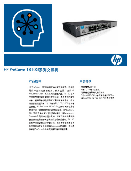
可由端口1上标配的PoE设备进行供电,因而使该交换 机成为无电源插座部署的理想选择。这一出色的灵活 性可帮助您在以太网电缆所及范围内,随意进行网络 扩展 • 1U机架安装尺寸(1810G-24交换机):提供机架安装 选项 • 新Kensington锁插槽:确保开放空间部署中的交换机 安全
保修与支持
• ProCurve终身保修:在产品使用期间提供下一工作日 提前更换服务(在大部分国家/地区提供)
• 管理密码:提供出色的安全性,仅允许授权的Web浏 览器界面访问
服务质量(QoS)
• 流量优先级(IEEE 802.1p):允许实时将流量分为8个优 先级,映射为8个队列
监控和诊断
• 新环路保护:环路检测和保护功能可防止网络环路, • 端口镜像:使端口上的流量可以同时发送到网络分析
提高网络可用性
器,以便进行监控
3hpprocurve1810g系列交换机规格hpprocurve1810g24交换机j9450ahpprocurve1810g8交换机j9449a端口22个自适应101001000端口ieee8023type10basetieee8023utype100basetxieee8023abtype1000baset介质类型automdix双工10baset100basetx半双工或全双工1000baset仅全双工2个双功能定制端口每个端口均可用作rj45101001000端口ieee8023type10basetieee8023utype100basetxieee8023ab1000baset千兆以太网或可用的minigbic插槽用于minigbic收发器1712长x4425宽x439高厘米674x1742x173英寸1u高196千克432磅全装载8mb闪存16mbsdram数据包缓冲区大小512kb安装在一个标准eia19英寸telco机架中包含硬件墙壁桌面和桌下安装47?s64字节数据包30?s64字节数据包高达357mpps64字节数据包48gbps8000个条目8个自适应101001000端口ieee8023type10basetieee8023utype100basetxieee8023abtype1000baset介质类型automdix双工10baset100basetx半双工或全双工1000baset仅全双工物理特性外形尺寸重量内存和处理器1163长x1963宽x439高厘米458x773x173英寸1u高054千克119磅全装载8mb闪存16mbsdram数据包缓冲区大小512kb墙壁天花板桌面和桌下安装39?s64字节数据包21?s64字节数据包高达119mpps64字节数据包16gbps8000个条目安装性能100mb延迟1000mb延迟吞吐率交换容量mac地址表大小工作环境工作温度工作相对湿度非工作存放温度非工作存放相对湿度海拔噪音电气特性最大散热量电压电流最大额定功率频率注0oc到40oc32of到104of40oc104of时15到95无凝结40oc到70oc40of到158of65oc149of时15到90无凝结高达3千米10000英尺功耗0db无风扇0oc到40oc32of到104of40oc104of时15到95无凝结40oc到70oc40of到158of65oc149of时15到
一光八电 中文 说明书 A5
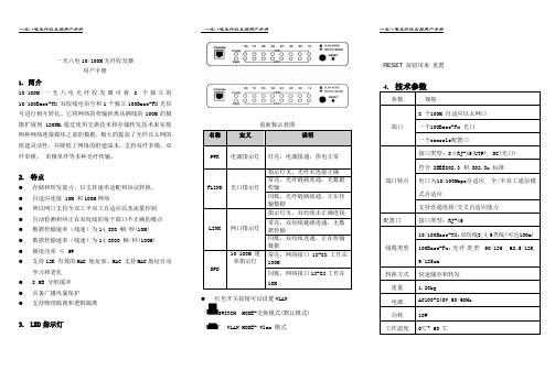
一光八电10/100M光纤收发器用户手册1.简介10/100M 一光八电光纤收发器可将8个独立的10/100Base-TX 双绞线电信号和1个独立100Base-FX光信号进行相互转化。
它将网络的传输距离从铜线的100M的极限扩展到120KM.通过使用交换技术和存储转发技术来实现两种网络连接媒体之前的数据,极大的提高了光纤以太网的组建灵活性,并降低了网络的组建成本,支持双纤多模,双纤单模,单模单纤等多种光纤传输。
2.特点●存储和转发能力,以支持速率适配和协议转换。
●自适应连接 10M 和100M网络●所以网口支持全双工半双工自适应以及流量控制●自动检测和纠正在双绞线的每个端口不正确的极点●数据传输速率(线速)为14,880 帧/秒(10M)●数据传输速率(线速)为14,8800 帧/秒(100M)●额度功率≤ 5W●支持12K 有效的MAC 地址表。
MAC 支持MAC地址自动学习和老化●8 MB 分组缓冲●具备广播风暴保护●支持物理隔离和逻辑隔离3.LED指示灯10/100M 一光八电光纤收发器前面板共有9组指示灯前面板示意图名称定义说明PWR 电源指示灯灯亮,电源接通,供电正常FLINK 光口指示灯指示灯灭,光纤未连接正确常亮,光纤链路连通,无数据传输闪烁,光纤链路接通,正在传输数据LINK 网口指示灯指示灯灭,双绞线未正确连接常亮,双绞线链路连通,无数据传输闪烁,双绞线连通,正在传输数据SPD10/100M 速率指示灯常亮,网络接口1X-8X工作在100M闪烁,网络接口1X-8X工作在10M●红色开关按钮可以设置VLAN‘SWITCH MODE-交换模式(默认模式)‘’ VLAN MODE- Vlan 模式RESET 按钮用来重置4.技术参数参数规格端口8 个100M 自适应以太网口一个100Base-Fx 光口一个console配置口端口特点接口类型: 8×RJ-45(UTP), SC(光口)符合 IEEE802.3 和 802.3u 标准电口为10/100Mbps自适应, 全/半双工通信模式自适应支持直通连接/交叉自适应能力配置口接口类型: RJ-45线缆类型10/100Base-TX:双绞线3,4,5类线(可达100m)100Base-Fx:光纤类型50/125 ,62.5/125,9/125um转换方式快速储存和转发重量 1.20kg电源AC100-240V,50/60Hz功耗10W工作温度0℃~ 60 ℃储存温度-40℃~ 70 ℃工作湿度20%-85% 无凝结储存湿度10%-90% 无凝结5.安装请按照下面的步骤安装收发器a)选择五类线和本设备连接,(直通式或者交叉式)RJ45 端口的引脚定义:Pin1:TX+ 数据发送正极Pin2:TX+ 数据发送正极Pin3:TX+ 数据发送正极Pin4:TX+ 数据发送正极Pin5, Pin6 ,Pin7 ,Pin8 闲置未用b)关掉设备电源,按照正确的连接结构进行光纤,收发器,以太网设备的连接c)光纤收发器之间连接是,本分的发(RX)连接对方的(TX), 本方的发(TX)连接对方的(RX)d)首先确定设备的额定电压是220V还是直流-48V,然后连接相应的电源线后,如PWR 量,设备供电正常e)打开以太网的电源开关,打开收发器电源开关,相应的指示灯亮和闪烁,安装完成6.装箱清单开箱之后根据收发器的型号,核对包装清单,如有遗失或损坏,请立即联系当地的经销商1)一光八电光纤收发器一台2)电源线一条3)说明书一本4)产品质量保修卡一光八电10/100M光纤收发器用户手册V1.1。
- 1、下载文档前请自行甄别文档内容的完整性,平台不提供额外的编辑、内容补充、找答案等附加服务。
- 2、"仅部分预览"的文档,不可在线预览部分如存在完整性等问题,可反馈申请退款(可完整预览的文档不适用该条件!)。
- 3、如文档侵犯您的权益,请联系客服反馈,我们会尽快为您处理(人工客服工作时间:9:00-18:30)。
1/10®BTA/BTB08 and T8 SeriesSNUBBERLESS ™, LOGIC LEVEL & STANDARD8A TRIAC SApril 2002 - Ed: 5AMAIN FEATURES:DESCRIPTIONAvailable either in through-hole or surface-mount packages, the BTA/BTB08 and T8 triac series is suitable for general purpose AC switching. They can be used as an ON/OFF function in applications such as static relays, heating regulation, induction motor starting circuits... or for phase control operation in light dimmers, motor speed controllers,...The snubberless versions (BTA/BTB...W and T8series) are specially recommended for use on inductive loads, thanks to their high commutation performances. By using an internal ceramic pad,the BTA series provides voltage insulated tab (rated at 2500V RMS) complying with UL standards (File ref.: E81734)Symbol Value Unit I T(RMS)8A V DRM /V RRM 600 and 800V I GT (Q 1)5 to 50mAABSOLUTE MAXIMUM RATINGSSymbol ParameterValueUnitI T(RMS)RMS on-state current (full sine wave)DP AK / D ²PAK IPAK / TO-220AB Tc = 110°C 8A TO-220AB Ins.Tc = 100°C I TSM Non repetitive surge peak on-state current (full cycle, Tj initial = 25°C) F = 50 Hz t = 20 ms 80AF = 60 Hzt = 16.7 ms84I ²t I ²t Value for fusingtp = 10 ms36A ²s dI/dt Critical rate of rise of on-state current I G = 2 x I GT , tr ≤ 100 ns F = 120 Hz Tj = 125°C 50A/µs I GM Peak gate currenttp = 20 µsTj = 125°C 4A P G(AV)Average gate power dissipation Tj = 125°C1W T stg T jStorage junction temperature range Operating junction temperature range- 40 to + 150- 40 to + 125°CBTA/BTB08 and T8 Series2/10ELECTRICAL CHARACTERISTICS (Tj = 25°C, unless otherwise specified)sSNUBBERLESS™ and LOGIC LEVEL (3 Quadrants)sSTANDARD (4 Quadrants)STATIC CHARACTERISTICSNote 1: minimum IGT is guaranted at 5% of IGT max.Note 2: for both polarities of A2 referenced to A1Symbol Test ConditionsQuadrantT8BTA/BTB08UnitT810T835TW SW CW BW I GT (1)V D = 12 V R L = 30 ΩI - II - III MAX.10355103550mA V GT I - II - III MAX. 1.3V V GD V D = V DRM R L = 3.3 k ΩTj = 125°C I - II - IIIMIN.0.2V I H (2)I T = 100 mA MAX.153510153550mA I L I G = 1.2 I GTI - III MAX.255010255070mA II306015306080dV/dt (2)V D = 67 %V DRM gate open Tj = 125°CMIN.4040020404001000V/µs (dI/dt)c (2)(dV/dt)c = 0.1 V/µs Tj = 125°C MIN.5.4- 3.5 5.4--A/ms(dV/dt)c = 10 V/µs Tj = 125°C 2.8- 1.5 2.8--Without snubber Tj = 125°C- 4.5-- 4.57Symbol Test ConditionsQuadrant BTA/BTB08UnitCB I GT (1)V D = 12 V R L = 30 ΩI - II - III IV MAX.255050100mA V GT ALL MAX. 1.3V V GD V D = V DRM R L = 3.3 k ΩTj = 125°C ALLMIN.0.2V I H (2)I T = 500 mA MAX.2550mA I L I G = 1.2 I GTI - III - IVMAX.4050mA II80100dV/dt (2)V D = 67 %V DRM gate open Tj = 125°CMIN.200400V/µs (dV/dt)c (2)(dI/dt)c = 3.5 A/ms Tj = 125°CMIN.510V/µsSymbol Test ConditionsValue Unit V TM (2)I TM = 11 A tp = 380 µs Tj = 25°C MAX. 1.55V V to (2)Threshold voltage Tj = 125°C MAX.0.85V R d (2)Dynamic resistance Tj = 125°C MAX.50m ΩI DRM I RRMV DRM = V RRMTj = 25°C MAX.5µA Tj = 125°C1mABTA/BTB08 and T8 Series3/10THERMAL RESISTANCESS = Copper surface under tabPRODUCT SELECTORBTB: non insulated TO-220AB packageSymbol ParameterValue Unit R th(j-c)Junction to case (AC)DPAK / D ²PAK IPAK / TO-220AB 1.6°C/WTO-220AB Insulated2.5R th(j-a)Junction to ambientS = 1 cm ²D ²PAK 45°C/WS = 0.5 cm ²DPAK70TO-220ABTO-220AB Insulated60IPAK100Part NumberVoltage (xxx)Sensitivity Type Package 600 V 800 V BTA/BTB08-xxxB X X 50 mA Standard TO-220AB BTA/BTB108-xxxBW X X 50 mA Snubberless TO-220AB BTA/BTB08-xxxC X X 25 mA Standard TO-220AB BTA/BTB08-xxxCW X X 35 mA Snubberless TO-220AB BTA/BTB08-xxxSW X X 10 mA Logic level TO-220AB BTA/BTB08-xxxTW X X 5 mA Logic level TO-220AB T810-xxxB X X 10 mA Logic level DP AK T810-xxxH X X 10 mA Logic level IP AK T835-xxxB X X 35mA Snubberless DP AK T835-xxxG X X 35 mA Snubberless D ²PAK T835-xxxHXX35 mASnubberlessIP AKBTA/BTB08 and T8 Series4/10ORDERING INFORMATIONOTHER INFORMATIONNote: xxx = voltage, yy = sensitivity, z = typePart NumberMarkingWeight Base quantity Packing mode BTA/BTB08-xxxyz BTA/BTB08xxxyz 2.3 g 250Bulk BTA/BTB08-xxxyzRG BTA/BTB08-xxxyz 2.3 g 50Tube T8yy-xxxB T8yyxxx 0.3 g 75Tube T8yy-xxxB-TR T8yyxxx 0.3 g 2500Tape & reel T8yy-xxxH T8yyxxx 0.4 g 75Tube T8yy-xxxG T8yyxxx 1.5 g 50Tube T8yy-xxxG-TRT8yyxxx1.5 g1000Tape & reelBTA/BTB08 and T8 Series5/10Fig. 1: Maximum power dissipation versus RMS on-state current (full cycle).Fig. 2-1: RMS on-state current versus case temperature (full cycle).Fig. 2-2: RMS on-state current versus ambient temperature (printed circuit board FR4, copper thickness: 35µm),full cycle.Fig. 3: Relative variation of thermal impedance versus pulse duration.Fig. 4: On-state characteristics (maximum values).Fig. 5: Surge peak on-state current versus number of cycles.BTA/BTB08 and T8 Series6/10Fig. 6: Non-repetitive surge peak on-state current for a sinusoidal pulse with width tp <10ms, and corresponding value of I²t.Fig. 7: Relative variation of gate trigger current,holding current and latching current versus junction temperature (typical values).Fig. 8-1: Relative variation of critical rate of decrease of main current versus (dV/dt)c (typical values). Snubberless & Logic Level TypesFig. 8-2: Relative variation of critical rate of decrease of main current versus (dV/dt)c (typical values). Standard TypesFig. 9: Relative variation of critical rate of decrease of main current versus junction temperature.Fig. 10: DP AK and D 2PAK Thermal resistance junction to ambient versus copper surface under tab (printed circuit board FR4, copper thickness:35µm).BTA/BTB08 and T8 Series PACKAGE MECHANICAL DATAFOOTPRINT DIMENSIONS (in millimeters)7/10BTA/BTB08 and T8 Series PACKAGE MECHANICAL DATAFOOTPRINT DIMENSIONS (in millimeters)8/10BTA/BTB08 and T8 Series PACKAGE MECHANICAL DATA9/10BTA/BTB08 and T8 SeriesPACKAGE MECHANICAL DATAInformation furnished is believed to be accurate and reliable. However, STMicroelectronics assumes no responsibility for the consequences of use of such information nor for any infringement of patents or other rights of third parties which may result from its use. No license is granted by implication or otherwise under any patent or patent rights of STMicroelectronics. Specifications mentioned in this publication are subject to change without notice. This publication supersedes and replaces all information previously supplied. STMicroelectronics products are not authorized for use as critical components in life support devices or systems without express written approval of STMicroelectronics.© The ST logo is a registered trademark of STMicroelectronics© 2002 STMicroelectronics - Printed in Italy - All Rights ReservedSTMicroelectronics GROUP OF COMPANIESAustralia - Brazil - Canada - China - Finland - France - GermanyHong Kong - India - Isreal - Italy - Japan - Malaysia - Malta - Morocco - SingaporeSpain - Sweden - Switzerland - United Kingdom - United States.10/10。