NP32N055ILE
NP系列微型磁力齿轮泵中文样本
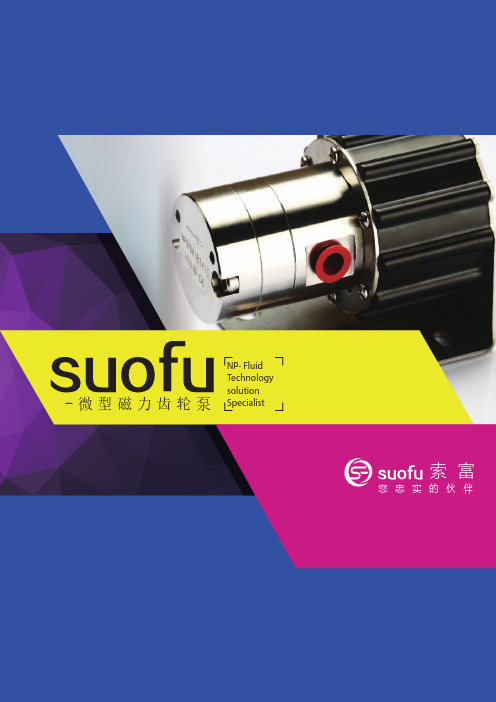
NP- FluidTechnologysolution-微型磁力齿轮泵Specialist索 富您忠实的伙伴您忠实的伙伴上海索富实业有限公司成立于2010,是一家以市场需求为先导、技术创新为核心、坚持为客户提供优质产品和服务的微型磁力齿轮泵公司。
我们的目标是成为世界领先的微型泵设计和生产者。
公司目前在上海拥有研发和销售中心,在福建三明市拥有生产基地。
公司人员来自外企管理和技术团队以及国内技师团队,具有微型特种泵15年以上的技术和市场经验以及40年的产品生产和管理经验。
公司拥有特种材料应用、专业型线设计、高精度加工、一次注塑成型、精密装配到检测的全套自主技术,已经获得12项专利,包含4项发明专利。
公司适应市场需求,每年都有新产品推向市场,都有新技术得到开发和应用。
项目进入中国创新创业大赛全国总决赛并获得省级二等奖。
全系列产品获得欧盟CE认证。
多年来我们的产品行销国内外,在医疗设备、化工装置、工程机械、商用机械、实验室分析、柴油机尾气后处理(SCR)、润滑系统、植保无人机、工业雾化系统、冷却系统、燃料电池、锂电池生产等领域得到广泛应用。
产品的稳定、长寿命、高压性能达到甚至超过欧美同类进口产品,获得国内外客户的好评。
我们一直致力于以高度的专业性和贴近客户的服务为您提供最适合需求的完整解决方案。
您的需求就是我们的使命。
企业简介Company pro le 上海索富实业有限公司成立于2010,是一家以市场需求为先导、技术创新为核心、坚持为客户提供优质产品和服务的微型磁力齿轮泵公司。
我们的目标是成为世界领先的微型泵设计和生产者。
公司目前在上海拥有研发和销售中心,在福建三明市拥有生产基地。
公司人员来自外企管理和技术团队以及国内技师团队,具有微型特种泵15年以上的技术和市场经验以及40年的产品生产和管理经验。
公司拥有特种材料应用、专业型线设计、高精度加工、一次注塑成型、精密装配到检测的全套自主技术,已经获得12项专利,包含4项发明专利。
曲拐箱油雾浓度操作说明书

使用的符号
当心!请勿忽视该警告,否则将损坏设备或危及人身安全 警告!该标志包含重要信息。 该字母标志仅为快速处理提示。
当心!在柴油机机体上进行焊接操作过程中必须拔去油雾探测器上的主 插头。
油雾警报复位
在按下油雾警报复位按钮之前, 确保柴油机内的油雾浓度低于爆炸下 限(LEL)。否则,将产生油雾爆炸的危险!
故障和排错 ......................................................................... 39
清洁新鲜空气孔 .........................................................................40 清洁红外过滤器 .........................................................................40 更换测量头内的空气滤片 ..............................................................41
操作说明 ............................................................................ 36
显示 .......................................................................................36 油雾警报复位 ............................................................................38
安装说明 ............................................................................ 12
Thinkcentre product books

Personal Systems Reference Lenovo® ThinkCentre Desktops January 2011 - Version 391Lenovo ThinkCentre M90/M90p(Eco Ultra Small, Small, Tower Form Factors)Visit /psref for the latest versionLenovo ® USB-to-DVI Monitor Adapter45K52961GB PC3-8500 DDR3 UDIMM 45J54342GB PC3-8500 DDR3 UDIMM 45J54351GB PC3-8500 DDR3 Low-Halogen SODIMM 55Y37062GB PC3-8500 DDR3 Low-Halogen SODIMM 55Y3707(UDIMM for SFF , Tower only; SODIMM for Eco USFF only)Kensington ®MicroSaver ®Cable Lock73P2582Kensington Twin Head Cable Lock45K1620NVIDIA ® GeForce ® 310 DMS59 (2-DVI, 2-VGA)57Y4167Lenovo ThinkCentre M58 Eco Ultra Small with dual Lenovo ThinkVision monitorsLenovo ThinkCentre M58 Small with Lenovo ThinkVision monitorLenovo ThinkCentre M58 SmallLenovo ThinkCentre M58 and M58p Eco Ultra Small, Small, TowerLenovo ThinkCentre M58 Eco Ultra Small☞☞☞☞☞☞☞☞☞☞☞Partial list of accessories supported on ThinkCentre M58 and M58pMemoryEco Ultra Small 8820/7359/7637/9961/7479/6136 use notebook memory:1GB PC3-8500 DDR3 Low-Halogen SODIMM 55Y3706 ann 06/23/09 1GB PC3-8500 DDR3 L-H SODIMM (25-Pack) 57Y4385 ann 06/23/09 2GB PC3-8500 DDR3 Low-Halogen SODIMM 55Y3707 ann 06/23/09 2GB PC3-8500 DDR3 L-H SODIMM (25-Pack) 57Y4386 ann 06/23/09 Small 8910/7360/6258/7638/9964/7483/7220/6137/6234, andTower 9960/7373/6239/9965/7484/7188/6138/6209/3063/3285/9728/ 7639 use desktop memory:1GB PC3-8500 DDR3 UDIMM 45J5434 ann 11/18/08 1GB PC3-8500 DDR3 UDIMM (25-Pack) 57Y4421 ann 11/10/09 2GB PC3-8500 DDR3 UDIMM 45J5435 ann 11/18/08 2GB PC3-8500 DDR3 UDIMM (25-Pack) 57Y4422 ann 11/10/09 More information at/support/desktopmemorycompatibilityOpticalAll:DVD-ROM DL SATA 1.5Gb/s 16X-48X Max4 41N5618 ann 09/26/06 Super Multi-Burner DL DVD±RW SATA Drive 41N5620 ann 09/26/06 Tower 9960/7373/6239/9965/7484/7188/6138/6209/3063/3285/9728/ 7639 support:Blu-ray™ Burner SA TA 1.5Gb/s Drive 45K1675 ann 03/31/09 Storage and removable storage250GB SATA 3.0Gb/s Disk (7200 rpm) 41N3015 ann 01/24/06 500GB SATA 3.0Gb/s Disk (7200 rpm) 43R1990 ann 11/06/07 1TB SATA 3.0Gb/s Disk (7200 rpm) 45J7918 ann 08/19/08 USB 2.0 Portable 320GB Hard Disk 45K1689 ann 03/17/09 USB 2.0 Portable 500GB Hard Disk 45K1690 ann 05/26/09 USB 2.0 Portable Secure 160GB Hard Disk 43R2018 ann 11/18/08 USB 2.0 Portable Secure 320GB Hard Disk 43R2019 ann 11/18/08 eSATA/USB 2.0 Secure 500GB Hard Drive 57Y4400 ann 01/07/10 USB 2.0 Portable DVD Burner 43N3264 ann 01/05/10 GraphicsSmall 8910/7360/6258/7638/9964/7483/7220/6137/6234 support Low Profi le:ADD2 DVI-D Monitor Connection (HDCP) 43R1985 ann 11/06/07 NVIDIA® Quadro® 256MB NVS 290(2-DVI or 2-VGA via DMS59 dongles) 43R1765 ann 12/18/07 NVIDIA GeForce® 310 512MB DMS59(2-DVI or 2-VGA via DMS59 dongles) 57Y4167 ann 03/02/10 Tower 9960/7373/6239/9965/7484/7188/6138/6209/3063/3285/9728/ 7639 support 75 watts max:ADD2 DVI-D Monitor Connection (HDCP) 43R1985 ann 11/06/07 NVIDIA Quadro 256MB NVS 290 43R1765 ann 12/18/07 NVIDIA Quadro 256MB NVS 295 (2-DP) 45K1669 ann 04/21/09 NVIDIA GeForce 310 512MB DMS59 57Y4167 ann 03/02/10 More information at /support/graphiccards KeyboardPreferred Pro USB Keyboard 73P5220 ann 06/21/05 Preferred Pro Full Size PS/2 Keyboard 31P7415 ann 06/04/02 Enhanced Performance USB Keyboard 73P2620 ann 03/23/04 Ultraslim Wireless Keyboard and Mouse52 57Y4700 ann 09/15/09 Lenovo® USB Fingerprint Keyboard 73P4730 ann 02/22/05 Lenovo USB Smartcard Keyboard 51J0155 ann 03/24/09 52 Wireless via 2.4GHz technology using a micro-size USB receiver. More information at /support/keyboardsMouseLenovo Optical Mouse (USB) 06P4069 ann 05/21/03 Lenovo ScrollPoint® Mouse (USB, Optical) 31P7405 ann 08/27/02 Lenovo Laser Mouse (USB) 41U3074 ann 01/23/07 Lenovo Wireless Laser Mouse - Black5245K1696ann 11/25/08 Lenovo Wireless Laser Mouse - Red/Black5251J0198 ann 11/25/08 More information at /support/mice MultimediaThinkPad® In-Ear Headphones6057Y4488ann 01/07/10 60 Has a 1.2 meter (3.9-foot) cable. Best when systems are in closeproximity. Example: SFF placed on a desk.SecurityKensington® MicroSaver® Cable Lock56 73P2582ann 12/29/03 Kensington Twin Head Cable Lock56 45K1620ann 09/30/08 Lenovo Security Cable Lock 57Y4303 ann 08/24/10 USB Gemplus GemPC Smart Card Reader 41N3040 ann 02/21/06 56 Attaching to any form factor not only secures the ThinkCentre tothe work area, but it also prevents users from opening the chassis itself.Mounting DeviceEco Ultra Small 8820/7359/7637/9961/7479/6136 supportunder desk mounting device:ThinkCentre Ultra Small Under Desk Mount 40Y8625 ann 09/06/05 MonitorsLenovo L2230x Wide 21.5" Monitor 5453HB1 ann 06/10/10 ThinkVision® L1711p 17" Monitor 5047HB2 ann 10/20/09 ThinkVision L1900p 19" Monitor 4431HE1 ann 11/11/08 ThinkVision L1951p Wide 19" Monitor 2448HB6 ann 10/20/09 ThinkVision L2250p Wide 22" Monitor 2572HB6 ann 10/20/09 ThinkVision L2251p Wide 22" Monitor 2572HD6 ann 10/20/09 ThinkVision L2251x Wide 22" Monitor 2578HB6 ann 10/20/09 ThinkVision L2321x Wide 23" Monitor 4014HB6 ann 06/10/10 ThinkVision L2440p Wide 24" Monitor 4420HB2 ann 09/17/08 More information at /thinkvisionMonitor Accessories46Eco Ultra Small 8820/7359/7637/9961/7479/6136 support:Lenovo Vertical PC and Monitor Stand II 41R4474 ann 01/27/09 All:Lenovo USB-to-DVI Monitor Adapter 45K5296 ann 05/12/09 DisplayPort™ to Single-link DVI-D Cable 45J7915 ann 08/05/08 DisplayPort to VGA Monitor Cable 57Y4393 ann 08/04/09 ThinkVision USB Soundbar 40Y7616 ann 08/23/05 ThinkVision Soundbar 45K1263 ann 09/16/08 Kensington MicroSaver Cable Lock56 73P2582ann 12/29/03 Kensington Twin Head Cable Lock56 45K1620ann 09/30/08 Lenovo Security Cable Lock 57Y4303 ann 08/24/10 ThinkCentre Extend Arm 57Y4352 ann 07/06/10 46 Compatible on selected Lenovo and ThinkVision monitors.More information at /support/monitoraccessoriesFor more information on desktop accessories, please visit:/support/accessories/support/desktopaccessories/support/securityOther accessories at /accessoriesAccessories Guide pdf at /accessoriesguideThinkCentre® M58, M58p Accessories Personal Systems Reference (PSREF)Lenovo ThinkCentre M70e Tower with Lenovo ThinkVision monitorLenovo ThinkCentre M70e Small with Lenovo ThinkVision monitorLenovo ThinkCentre M70e Smallwith optional PS/2 keyboard and mouse ports Lenovo ThinkCentre M70e Small and TowerLenovo ThinkCentre M70e Small andLenovo ThinkCentre M70e TowerThinkCentre® M70e Small (0809) - TopSeller (Windows 7)Personal Systems Reference (PSREF)Partial list of accessories supported on ThinkCentre M70eMemory1GB PC3-8500 DDR3 UDIMM 45J5434 ann 11/18/08 1GB PC3-8500 DDR3 UDIMM (25-Pack) 57Y4421 ann 11/10/09 2GB PC3-8500 DDR3 UDIMM 45J5435 ann 11/18/08 2GB PC3-8500 DDR3 UDIMM (25-Pack) 57Y4422 ann 11/10/09 More information at/support/desktopmemorycompatibilityOpticalDVD-ROM DL SATA 1.5Gb/s 16X-48X Max441N5618 ann 09/26/06 Super Multi-Burner DL DVD±RW SATA Drive 41N5620 ann 09/26/06Storage and removable storage250GB SATA 3.0Gb/s Disk (7200 rpm) 41N3015 ann 01/24/06 500GB SATA 3.0Gb/s Disk (7200 rpm) 43R1990 ann 11/06/07 USB 2.0 Portable 320GB Hard Disk 45K1689 ann 03/17/09 USB 2.0 Portable 500GB Hard Disk 45K1690 ann 05/26/09 USB 2.0 Portable Secure 160GB Hard Disk 43R2018 ann 11/18/08 USB 2.0 Portable Secure 320GB Hard Disk 43R2019 ann 11/18/08 eSA TA/USB 2.0 Secure 500GB Hard Drive 53 57Y4400ann 01/07/10 USB 2.0 Portable DVD Burner 43N3264 ann 01/05/10 53 USB-only attach.GraphicsSmall 0809/0822/0830/0833/0843 support Low Profi le:DisplayPort™ to Single-link DVI-D Cable50 45J7915ann 08/05/08 DisplayPort to VGA Monitor Cable50 57Y4393ann 08/04/09 ADD2 DVI-D Monitor Connection (HDCP) 43R1985 ann 11/06/07 NVIDIA® Quadro® 512MB FX 380 LP(DP, DVI with a DVI to VGA converter) 57Y4396 ann 02/02/10 NVIDIA GeForce® 310 512MB (DP, VGA) 57Y4397 ann 02/02/10 NVIDIA GeForce 310 512MB DMS59(2-DVI or 2-VGA via DMS59 dongles) 57Y4167 ann 03/02/10 Tower 0806/0829/0832/0842 support:DisplayPort to Single-link DVI-D Cable50 45J7915ann 08/05/08 DisplayPort to VGA Monitor Cable50 57Y4393ann 08/04/09 ADD2 DVI-D Monitor Connection (HDCP) 43R1985 ann 11/06/07 NVIDIA GeForce 310 512MB (DP, VGA) 57Y4397 ann 02/02/10 NVIDIA GeForce 310 512MB DMS59 57Y4167 ann 03/02/10 50 Attaches to theThinkCentre compatible DisplayPort graphics card. More information at /support/graphiccardsKeyboardPreferred Pro USB Keyboard 73P5220 ann 06/21/05 Preferred Pro Full Size PS/2 Keyboard 31P7415 ann 06/04/02 Enhanced Performance USB Keyboard 73P2620 ann 03/23/04 Ultraslim Wireless Keyboard and Mouse52 57Y4700ann 09/15/09 ThinkPad USB Keyboard with T rackPoint 55Y9003 ann 08/18/09 Lenovo® USB Fingerprint Keyboard 73P4730 ann 02/22/05 Lenovo USB Smartcard Keyboard 51J0155 ann 03/24/09 52 Wireless via 2.4GHz technology using a micro-size USB receiver.More information at /support/keyboardsMouseLenovo Optical Mouse (USB) 06P4069 ann 05/21/03 ThinkPad® USB Laser Mouse 57Y4635 ann 12/15/09 Lenovo ScrollPoint® Mouse (USB, Optical) 31P7405 ann 08/27/02 Lenovo Laser Mouse (USB) 41U3074 ann 01/23/07 Lenovo Wireless Laser Mouse - Black52 45K1696ann 11/25/08 Lenovo Wireless Laser Mouse - Red/Black52 51J0198ann 11/25/08 More information at /support/mice MultimediaThinkPad In-Ear Headphones6057Y4488ann 01/07/10 60 Has a 1.2 meter (3.9-foot) cable. Best when systems are in closeproximity. Example: SFF placed on a desk.ModemUSB 2.0 Lenovo Modem 43R1814ann 02/26/08 SecurityKensington® MicroSaver® Cable Lock5673P2582ann 12/29/03 Kensington T win Head Cable Lock5645K1620ann 09/30/08 Lenovo Security Cable Lock 57Y4303 ann 08/24/10 USB Gemplus GemPC Smart Card Reader41N3040ann 02/21/06 56 Attaching to any form factor not only secures the ThinkCentre tothe work area, but it also prevents users from opening the chassis itself.MonitorsLenovo D186 Wide 18.5" Monitor 2580AB1 ann 01/12/10 Lenovo L2230x Wide 21.5" Monitor 5453HB1 ann 06/10/10 ThinkVision® L1711p 17" Monitor 5047HB2 ann 10/20/09 ThinkVision L1900p 19" Monitor 4431HE1 ann 11/11/08 ThinkVision L1951p Wide 19" Monitor 2448HB6 ann 10/20/09 ThinkVision L2250p Wide 22" Monitor 2572HB6 ann 10/20/09 ThinkVision L2251p Wide 22" Monitor 2572HD6 ann 10/20/09 ThinkVision L2251x Wide 22" Monitor 2578HB6 ann 10/20/09 ThinkVision L2321x Wide 23" Monitor 4014HB6 ann 06/10/10 ThinkVision L2440p Wide 24" Monitor 4420HB2 ann 09/17/08 More information at /thinkvisionMonitor Accessories46Lenovo USB-to-DVI Monitor Adapter 45K5296 ann 05/12/09 ThinkVision USB Soundbar 40Y7616 ann 08/23/05 ThinkVision Soundbar 45K1263 ann 09/16/08 Kensington MicroSaver Cable Lock56 73P2582ann 12/29/03 Kensington Twin Head Cable Lock56 45K1620ann 09/30/08 Lenovo Security Cable Lock 57Y4303 ann 08/24/10 ThinkCentre Extend Arm 57Y4352 ann 07/06/10 46 Compatible on selected Lenovo and ThinkVision monitors.More information at /support/monitoraccessoriesFor more information on desktop accessories, please visit:/support/accessories/support/desktopaccessories/support/securityOther accessories at /accessoriesAccessories Guide pdf at /accessoriesguideThinkCentre® M70e Accessories Personal Systems Reference (PSREF)Lenovo ThinkCentre M75e Tower with Lenovo ThinkVision monitorLenovo ThinkCentre M75e Small with Lenovo ThinkVision monitorLenovo ThinkCentre M75e SmallLenovo ThinkCentre M75e Small and TowerLenovo ThinkCentre M75e Small andLenovo ThinkCentre M75e Tower。
IR公司_大功率MOS管选型

I DContinuous Drain Current(A)70°Micro3Surface Mount PackagesV (BR)DSSDrain-to-Source Breakdown Voltage (V)R DS(on)On-State Resistance ()ΩI D Continuous Drain Current 25°C(A)R ΘMax.Thermal Resistance (°C/W)1FaxonDemand Number Case Outline KeyPartNumberPD Max.PowerDissipation (W)N-ChannelLogic LevelIRLML2402*912570.54200.25 1.20.95230H1IRLML2803912580.54300.251.20.93230P-ChannelLogic LevelIRLML6302*912590.54-200.6-0.62-4.8230H1IRLML5103912600.54-300.6-0.61-4.8230* Indicates low VGS(th), which can operate at VGS = 2.7VMeasured at ambient for Micro3, Micro6, Micro8, SO-8, and SOT-223 package styles. All others measured at case.1Micro3SO-8D-PakD -PakSOT-227Micro6SOT-223Micro82 Illustrations not to scaleI DContinuous Drain Current(A)70°Micro6Surface Mount PackagesV (BR)DSSDrain-to-Source Breakdown Voltage (V)R DS(on)On-State Resistance ()ΩI D Continuous Drain Current 25°C(A)R ΘMax.Thermal Resistance (°C/W)1FaxonDemand Number Case Outline KeyPartNumberPD Max.PowerDissipation (W)N-ChannelLogic LevelIRLMS1902915401.7200.10 3.2 2.675H2IRLMS1503915081.7300.103.22.675P-ChannelLogic LevelIRLMS6702*914141.7-200.20-2.3-1.975H2IRLMS5703914131.7-300.20-2.3-1.975* Indicates low VGS(th), which can operate at VGS = 2.7VMeasured at ambient for Micro3, Micro6, Micro8, SO-8, and SOT-223 package styles. All others measured at case.1Micro3SO-8D-PakD -PakSOT-227Micro6SOT-223Micro82 Illustrations not to scaleI DContinuous Drain Current(A)70°Micro8Surface Mount PackagesV (BR)DSSDrain-to-Source Breakdown Voltage (V)R DS(on)On-State Resistance ()ΩI D Continuous Drain Current 25°C(A)R ΘMax.Thermal Resistance (°C/W)1FaxonDemand Number Case Outline KeyPart NumberP D Max.PowerDissipation (W)N-Channel Logic LevelIRF7601* 912611.820 0.035 5.7 4.6 70 H3IRF7603 912621.830 0.035 5.6 4.5 70Dual N-Channel Logic LevelIRF7501* 912651.220 0.135 2.4 1.9 100 H3IRF7503 912661.2530 0.135 2.4 1.9 100P-Channel Logic LevelIRF7604* 912631.8-20 0.09 -3.6 -2.9 70 H3IRF7606 912641.8-30 0.09 -3.6 -2.9 70Dual P-Channel Logic LevelIRF7504* 912671.25-20 0.27 -1.7 -1.4 100 H3IRF7506 912681.25-30 0.27 -1.7 -1.4 100Dual N- and P-Channel Logic LevelIRF7507* 912691.2520 0.1352.4 1.9 100 H3-20 0.27 -1.7 -1.4IRF7509 912701.2530 0.135 2.4 1.9 100-30 0.27 -1.7 -1.4* Indicates low VGS(th), which can operate at VGS = 2.7VMeasured at ambient for Micro3, Micro6, Micro8, SO-8, and SOT-223 package styles. All others measured at case.1Micro3SO-8D-Pak D -PakSOT-227Micro6SOT-223Micro8 2 Illustrations not to scaleI DContinuous Drain Current(A)70°SO-8Surface Mount PackagesV (BR)DSSDrain-to-Source Breakdown Voltage (V)R DS(on)On-State Resistance ()ΩI D Continuous Drain Current 25°C(A)R ΘMax.Thermal Resistance (°C/W)1FaxonDemand Number Case Outline KeyPart Number P D Max.PowerDissipation (W)N-ChannelIRF7413913302.5300.011139.250H4IRF7413A 916132.5300.0135128.450IRF9410915622.5300.0375.850Dual N-ChannelIRF7311914352.0200.029 6.6 5.362.5H4IRF7313914802.0300.029 6.5 5.262.5IRF7333917002.0300.10 3.5 2.862.5917002.0300.050 4.9 3.962.5IRF9956915592.0300.103.52.862.5Dual P-ChannelIRF7314914352.0-200.058-5.3-4.362.5H4IRF7316915052.0-300.058-4.9-3.962.5IRF9953915602.0-300.25-2.3-1.862.5* Indicates low VGS(th), which can operate at VGS = 2.7VMeasured at ambient for Micro3, Micro6, Micro8, SO-8, and SOT-223 package styles. All others measured at case.1Micro3SO-8D-PakD -PakSOT-227Micro6SOT-223Micro82 Illustrations not to scaleI DContinuous Drain Current(A)70°SO-8Surface Mount PackagesV (BR)DSSDrain-to-Source Breakdown Voltage (V)R DS(on)On-State Resistance ()ΩI D Continuous Drain Current 25°C(A)RΘMax.ThermalResistance(°C/W)1FaxonDemand Number Case Outline KeyPart NumberP D Max.PowerDissipation (W)Dual N- and P-ChannelIRF7317 915682.020 0.029 6.6 5.3 62.5 H42.0-20 0.058 -5.3 -4.3 62.5IRF9952 915622.030 0.103.5 2.8 62.5915622.0-30 0.25 -2.3 -1.8 62.5IRF7319 916062.030 0.029 6.5 5.2 62.52.0-30 0.058 -4.9 -3.9 62.5* Indicates low VGS(th), which can operate at VGS = 2.7VMeasured at ambient for Micro3, Micro6, Micro8, SO-8, and SOT-223 package styles. All others measured at case.1Micro3SO-8D-Pak D -PakSOT-227Micro6SOT-223Micro8 2 Illustrations not to scaleI DContinuous Drain Current(A)70°SO-8Surface Mount PackagesV (BR)DSSDrain-to-Source Breakdown Voltage (V)R DS(on)On-State Resistance ()ΩI D Continuous Drain Current 25°C(A)R ΘMax.Thermal Resistance (°C/W)1FaxonDemand Number Case Outline KeyPart Number P D Max.PowerDissipation (W)N-ChannelLogic LevelIRF7401912442.5200.0228.77.050H4IRF7201911002.5300.0307.0 5.650IRF7403912452.5300.0228.55.450Dual N-ChannelLogic LevelIRF7101908712.0200.10 3.5 2.362.5H4IRF7301912382.0200.050 5.2 4.162.5IRF7303912392.0300.050 4.9 3.962.5IRF7103910952.0500.1303.02.362.5P-ChannelLogic LevelIRF7204911032.5-200.060-5.3-4.250H4IRF7404912462.5-200.040-6.7-5.450IRF7205911042.5-300.070-4.6-3.750IRF7406912472.5-300.045-5.8-3.750IRF7416913562.5-300.02-10-7.150* Indicates low VGS(th), which can operate at VGS = 2.7VMeasured at ambient for Micro3, Micro6, Micro8, SO-8, and SOT-223 package styles. All others measured at case.1Micro3SO-8D-PakD -PakSOT-227Micro6SOT-223Micro82 Illustrations not to scaleI DContinuous Drain Current(A)70°SO-8Surface Mount PackagesV (BR)DSSDrain-to-Source Breakdown Voltage (V)R DS(on)On-State Resistance ()ΩI D Continuous Drain Current 25°C(A)R ΘMax.Thermal Resistance (°C/W)1FaxonDemand Number Case Outline KeyPart Number P D Max.PowerDissipation (W)Dual P-ChannelLogic LevelIRF7104910962.0-200.250-2.3-1.862.5H4IRF7304912402.0-200.090-4.3-3.462.5IRF7306912412.0-300.10-3.6-2.962.5Dual N- and P-Channe Logic LevelIRF7307912421.4200.050 4.3 3.490H4-200.090-3.6-2.9IRF7105910972.0250.1093.5 2.862.52-250.25-2.3-1.862IRF7309912432.0300.050 4.9 3.962.5-300.10-3.6-2.9* Indicates low VGS(th), which can operate at VGS = 2.7VMeasured at ambient for Micro3, Micro6, Micro8, SO-8, and SOT-223 package styles. All others measured at case.1Micro3SO-8D-PakD -PakSOT-227Micro6SOT-223Micro82 Illustrations not to scaleI DContinuous Drain Current(A)70°SOT-223Surface Mount PackagesV (BR)DSSDrain-to-Source Breakdown Voltage (V)R DS(on)On-State Resistance ()ΩI D Continuous Drain Current 25°C(A)R ΘMax.Thermal Resistance (°C/W)1FaxonDemand Number Case Outline KeyPart Number P D Max.PowerDissipation (W)N-ChannelIRFL4105913812.1550.045 3.7 3.060H6IRFL110908612.01000.54 1.50.9660IRFL4310913682.11000.20 1.6 1.360IRFL21090868 2.02001.50.960.660IRFL214908622.02502.00.790.560P-ChannelIRFL9110908642.0-1001.2-1.1-0.6960H6N-ChannelLogic LevelIRLL3303913792.1300.031 4.6 3.760H6IRLL014N 914992.1550.14 2.0 1.660IRLL2705913802.1550.043.83.060* Indicates low VGS(th), which can operate at VGS = 2.7VMeasured at ambient for Micro3, Micro6, Micro8, SO-8, and SOT-223 package styles. All others measured at case.1Micro3SO-8D-PakD -PakSOT-227Micro6SOT-223Micro82 Illustrations not to scaleI DContinuous Drain Current(A)100°D-PakSurface Mount PackagesV (BR)DSSDrain-to-Source Breakdown Voltage (V)R DS(on)On-State Resistance ()ΩI D Continuous Drain Current 25°C(A)R ΘMax.Thermal Resistance (°C/W)1FaxonDemand Number Case Outline KeyPart Number P D Max.PowerDissipation (W)N-ChannelIRFR33039164257300.0313321 2.2H7IRFR024N9133638550.0751610 3.3IRFR41059130248550.0452516 2.7IRFR12059131869550.0273723 1.8IRFR11090524251000.54 4.3 2.75IRFR120N 91365391000.219.1 5.8 3.2IRFR391091364521000.11159.5 2.4IRFR2109052625200 1.5 2.6 1.75IRFR22090525422000.8 4.833IRFR21490703252502 2.2 1.45IRFR2249060042250 1.1 3.8 2.43IRFR3109059725400 3.6 1.7 1.15IRFR3209059842400 1.8 3.123IRFR42090599425003 2.4 1.53IRFRC2090637426004.421.33* Indicates low VGS(th), which can operate at VGS = 2.7VMeasured at ambient for Micro3, Micro6, Micro8, SO-8, and SOT-223 package styles. All others measured at case.1Micro3SO-8D-PakD -PakSOT-227Micro6SOT-223Micro82 Illustrations not to scaleI DContinuous Drain Current(A)100°D-PakSurface Mount PackagesV (BR)DSSDrain-to-Source Breakdown Voltage (V)R DS(on)On-State Resistance ()ΩI D Continuous Drain Current 25°C(A)R ΘMax.Thermal Resistance (°C/W)1FaxonDemand Number Case Outline KeyPart Number P D Max.PowerDissipation (W)P-ChannelIRFR55059161057-550.11-18-11 2.2H7IRFR53059140289-550.065-28-18 1.4IRFR90149065425-600.5-5.1-3.25IRFR90249065542-600.28-8.8-5.63IRFR91109051925-100 1.2-3.1-25IRFR91209052042-1000.6-5.6-3.63IRFR9120N 9150739-1000.48-6.5-4.1 3.2IRFR92109052125-2003-1.9-1.25IRFR92209052242-200 1.5-3.6-2.33IRFR92149165850-250 3.0-2.7-1.7 2.5IRFR93109166350-4007.0-1.8-1.12.5* Indicates low VGS(th), which can operate at VGS = 2.7VMeasured at ambient for Micro3, Micro6, Micro8, SO-8, and SOT-223 package styles. All others measured at case.1Micro3SO-8D-PakD -PakSOT-227Micro6SOT-223Micro82 Illustrations not to scaleI DContinuous Drain Current(A)100°D-PakSurface Mount PackagesV (BR)DSSDrain-to-Source Breakdown Voltage (V)R DS(on)On-State Resistance ()ΩI D Continuous Drain Current 25°C(A)R ΘMax.Thermal Resistance (°C/W)1FaxonDemand Number Case Outline KeyPart Number P D Max.PowerDissipation (W)N-ChannelLogic LevelIRLR27039133538300.0452214 3.3H7IRLR33039131657300.0313321 2.2IRLR31039133369300.0194629 1.8IRLR024N 9136338550.0651711 3.3IRLR27059131746550.042415 2.7IRLR29059133469550.0273623 1.8IRLR120N 91541391000.18511 6.9 3.2IRLR341091607521000.10159.52.4* Indicates low VGS(th), which can operate at VGS = 2.7VMeasured at ambient for Micro3, Micro6, Micro8, SO-8, and SOT-223 package styles. All others measured at case.1Micro3SO-8D-PakD -PakSOT-227Micro6SOT-223Micro82 Illustrations not to scaleI DContinuous Drain Current(A)100°D 2PakSurface Mount PackagesV (BR)DSSDrain-to-Source Breakdown Voltage (V)R DS(on)On-State Resistance ()ΩI D Continuous Drain Current 25°C(A)R ΘMax.Thermal Resistance (°C/W)1FaxonDemand Number Case Outline KeyPart NumberP D Max.PowerDissipation (W)N-ChannelIRFZ24NS 913554555 0.07 17 12 3.3 H10IRFZ34NS 913116855 0.04 29 20 2.2IRFZ44NS 9131511055 0.022 49 35 1.4IRFZ46NS 9130512055 0.020 53 37 1.3IRFZ48NS 9140814055 0.016 64 45 1.1IRF1010NS 913723.855 0.011 84 60 40IRF3205S 9130420055 0.008 110 80 0.75IRFZ44ES 9171411060 0.023 48 34 1.4IRF1010ES 9172017060 0.012 83 59 0.90IRF2807S 9151815075 0.013 71 50 1.0IRF520NS 9134047100 0.2 9.5 6.7 3.2IRF530NS 9135263100 0.11 15 11 2.4IRF540NS 91342110100 0.052 27 19 1.6IRF1310NS 91514120100 0.036 36 25 1.3IRF3710S 91310150100 0.028 46 33 1.0IRF3315S 9161794150 0.082 21 15 1.6IRF3415S 91509150150 0.042 37 26 1.0IRFBC20S 9.101450600 4.4 2.2 1.4 2.5IRFBC30S 9101574600 2.2 3.6 2.3 1.7IRFBC40S 91016130600 1.2 6.2 3.9 1.0* Indicates low VGS(th), which can operate at VGS = 2.7VMeasured at ambient for Micro3, Micro6, Micro8, SO-8, and SOT-223 package styles. All others measured at case.1Micro3SO-8D-Pak D -PakSOT-227Micro6SOT-223Micro8 2 Illustrations not to scaleI DContinuous Drain Current(A)100°D 2PakSurface Mount PackagesV (BR)DSSDrain-to-Source Breakdown Voltage (V)R DS(on)On-State Resistance ()ΩI D Continuous Drain Current 25°C(A)R ΘMax.Thermal Resistance (°C/W)1FaxonDemandNumberCase Outline KeyPart NumberP D Max.PowerDissipation (W)IRFBF20S 9166554900 8.0 1.7 1.1 2.3 H10P-ChannelIRF5305S 91386110-55 0.06 -31 -22 1.4 H10IRF4905S 914783.8-55 0.02 -74 -52 40IRF9520NS 9152247-100 0.48 -6.7 -4.8 3.2IRF9530NS 9152375-100 0.20 -14 -9.9 2.0IRF9540NS 9148394-100 0.117 -19 -13 1.6IRF5210S 91405150-100 0.06 -35 -25 1.0* Indicates low VGS(th), which can operate at VGS = 2.7VMeasured at ambient for Micro3, Micro6, Micro8, SO-8, and SOT-223 package styles. All others measured at case.1Micro3SO-8D-Pak D -PakSOT-227Micro6SOT-223Micro8 2 Illustrations not to scaleI DContinuous Drain Current(A)100°D 2PakSurface Mount PackagesV (BR)DSSDrain-to-Source Breakdown Voltage (V)R DS(on)On-State Resistance ()ΩI D Continuous Drain Current 25°C(A)R ΘMax.Thermal Resistance (°C/W)1FaxonDemand Number Case Outline KeyPart NumberP D Max.PowerDissipation (W)N-Channel Logic LevelIRL3302S 916925720 0.020 39 25 2.2 H10IRL3202S916756920 0.016 48 30 1.8IRL3102S 916918920 0.013 61 39 1.4IRL3402S 9169311020 0.01 85 54 1.1IRL3502S 9167614020 0.007 110 67 0.89IRL2703S 913604530 0.04 24 17 3.3IRL3303S 913236830 0.026 38 27 2.2IRL3103S 9133811030 0.014 64 45 1.4IRL2203NS 9136717030 0.007 116 82 0.90IRL3803S 9131920030 0.006 140 98 0.75IRLZ24NS 913584555 0.06 18 13 3.3IRLZ34NS 913086855 0.035 30 21 2.2IRLZ44NS 9134711055 0.022 47 33 1.4IRL3705NS 9150217055 0.01 89 63 0.90IRL2505S 9132620055 0.008 104 74 0.75IRLZ44S 9090615060 0.028 50 36 1.0IRL530NS 9134963100 0.1 15 11 2.4IRL2910S 91376150100 0.026 48 34 1.0* Indicates low VGS(th), which can operate at VGS = 2.7VMeasured at ambient for Micro3, Micro6, Micro8, SO-8, and SOT-223 package styles. All others measured at case.1Micro3SO-8D-Pak D -PakSOT-227Micro6SOT-223Micro8 2 Illustrations not to scaleI DContinuous Drain Current(A)100°SOT-227Surface Mount PackagesV (BR)DSSDrain-to-Source Breakdown Voltage (V)R DS(on)On-State Resistance ()ΩI D Continuous DrainCurrent 25°C(A)RΘMax.Thermal Resistance (°C/W)1FaxonDemand Number Case Outline KeyPart Number P D Max.PowerDissipation (W)N-ChannelFully Isolated Low ChargeFA38SA50LC 916155005000.1338240.25H21FA57SA50LC916506255000.0857360.20* Indicates low VGS(th), which can operate at VGS = 2.7VMeasured at ambient for Micro3, Micro6, Micro8, SO-8, and SOT-223 package styles. All others measured at case.1Micro3SO-8D-PakD -PakSOT-227Micro6SOT-223Micro82 Illustrations not to scaleI DContinuous Drain Current(A)100°I-PakThrough-Hole PackagesV (BR)DSSDrain-to-Source Breakdown Voltage (V)R DS(on)On-State Resistance ()ΩI D Continuous Drain Current 25°C(A)R ΘMax.Thermal Resistance (°C/W)1FaxonDemand Number Case Outline KeyPart Number P D Max.PowerDissipation (W)N-ChannelIRFU33039164257300.0313321 2.2H8IRFU024N 9133638550.0751610 3.3IRFU41059130248550.0452519 2.7IRFU12059131869550.0273723 1.8IRFU11090524251000.54 4.3 2.7 5.0IRFU120N 91365391000.219.1 5.8 3.2IRFU391091364521000.11159.5 2.4IRFU2109052625200 1.5 2.6 1.7 5.0IRFU22090525422000.80 4.8 3.0 3.0IRFU2149070325250 2.0 2.2 1.4 5.0IRFU2249060042250 1.1 3.8 2.4 3.0IRFU3109059725400 3.6 1.7 1.1 5.0IRFU3209059842400 1.8 3.1 2.0 3.0IRFU4209059942500 3.0 2.4 1.5 3.0IRFUC2090637426004.42.01.33.0I-PakTO-220 FullPakTO-262TO-247HEXDIPTO-220AB Illustrations not to scale** Not ratedI DContinuous Drain Current(A)100°I-PakThrough-Hole PackagesV (BR)DSSDrain-to-Source Breakdown Voltage (V)R DS(on)On-State Resistance ()ΩI D Continuous Drain Current 25°C(A)R ΘMax.Thermal Resistance (°C/W)1FaxonDemand Number Case Outline KeyPart Number P D Max.PowerDissipation (W)P-ChannelIRFU55059161057-550.11-18-11 2.2H8IRFU53059140289-550.065-28-18 1.4IRFU90149065425-600.50-5.1-3.2 5.0IRFU90249065542-600.28-8.8-5.6 3.0IRFU91109051925-100 1.2-3.1-2.0 5.0IRFU91209052042-1000.60-5.6-3.6 3.0IRFU9120N 9150739-1000.48-6.5-4.1 3.2IRFU92109052125-200 3.0-1.9-1.2 5.0IRFU92209052242-200 1.5-3.6-2.3 3.0IRFU92149165850-2503.0-2.7-1.7 2.5IRFU93109166350-4007.0-1.8-1.12.5N-ChannelLogic LevelIRLU27039133538300.0452214 3.3H8IRLU33039131657300.0313321 2.2IRLU31039133369300.0194629 1.8IRLU024N 9136338550.0651711 3.3IRLU27059131746550.04241715IRLU29059133469550.0273623 1.8IRLU120N 91541391000.18511 6.9 3.2IRLU341091607521000.10159.52.4I-PakTO-220 FullPakTO-262TO-247HEXDIPTO-220AB Illustrations not to scale** Not ratedI DContinuous Drain Current(A)100°HEXDIPThrough-Hole PackagesV (BR)DSSDrain-to-Source Breakdown Voltage (V)R DS(on)On-State Resistance ()ΩI D Continuous Drain Current 25°C(A)R ΘMax.Thermal Resistance (°C/W)1FaxonDemand Number Case Outline KeyPart Number P D Max.PowerDissipation (W)N-ChannelIRFD014907001.3600.2 1.7 1.2120H9IRFD024906991.3600.1 2.5 1.8120IRFD110903281.31000.54 1.00.71120IRFD120903851.31000.27 1.30.94120IRFD210903861.3200 1.50.60.38120IRFD220904171.32000.80.80.50120IRFD214912711.3250 2.00.570.32120IRFD224912721.3250 1.10.760.43120IRFD310912251.3400 3.60.420.23120IRFD320912261.3400 1.80.600.33120IRFD420912271.3500 3.00.460.26120IRFDC20912281.36004.40.320.21120I-PakTO-220 FullPakTO-262TO-247HEXDIPTO-220AB Illustrations not to scale** Not ratedI D Continuous Drain Current (A)100°TO-220Qg TotalGate Charge(nC)Through-Hole PackagesV (BR)DSSDrain-to-Source Breakdown Voltage (V)R DS(on)On-State Resistance ()ΩI D Continuous Drain Current 25°C (A)R ΘMax.Thermal Resistance(°C/W)1Faxon Demand Number Case OutlineKeyPart Number P D Max.Power Dissipation (W)N-ChannelLow ChargeIRF737LC91314743000.75 6.1** 1.7 3.9H11IRF740LC 910681254000.5510** 1.039IRF840LC 910691255000.858.0** 1.039IRFBC40LC910701256001.26.2**1.039I-PakTO-220 FullPakTO-262TO-247HEXDIPTO-220AB Illustrations not to scale** Not ratedI DContinuous Drain Current(A)100°TO-220ABThrough-Hole PackagesV (BR)DSSDrain-to-Source Breakdown Voltage (V)R DS(on)On-State Resistance ()ΩI D Continuous Drain Current 25°C(A)R ΘMax.Thermal Resistance (°C/W)1FaxonDemand Number Case Outline KeyPart Number P D Max.PowerDissipation (W)N-ChannelIRFZ24N 9135445550.071712 3.3H12IRFZ34N9127656550.042618 2.7IRFZ44N 9130383550.0244129 1.8IRFZ46N 9127788550.024633 1.7IRFZ48N 9140694550.0165337 1.6IRF1010N 91278130550.0127251 1.2IRF320591279150550.0089869 1.0IRFZ34E 9167268600.0422820 2.2IRFZ44E 91671110600.0234834 1.4IRF1010E 91670170600.01281570.90IRF280791517150750.0137150 1.0IRF520N 91339471000.209.5 6.79.5IRF530N 91351601000.111511 2.4IRF540N 91341941000.0522719 1.6IRF1310N 916111201000.0363625 1.3IRF3710913091501000.0284633 1.0IRF331591623941500.0822115 1.6IRF3415914771501500.0423726 1.0IRFBC209062350600 4.4 2.2 1.4 2.5IRFBC309048274600 2.2 3.6 2.3 1.7IRFBC4090506125600 1.2 6.2 3.9 1.0IRFBE2090610548006.51.81.22.3I-PakTO-220 FullPakTO-262TO-247HEXDIPTO-220AB Illustrations not to scale** Not ratedI DContinuous Drain Current(A)100°TO-220ABThrough-Hole PackagesV (BR)DSSDrain-to-Source Breakdown Voltage (V)R DS(on)On-State Resistance ()ΩI D Continuous Drain Current 25°C(A)R ΘMax.Thermal Resistance (°C/W)1FaxonDemand Number Case Outline KeyPart Number P D Max.PowerDissipation (W)IRFBE3090613125800 3.0 4.1 2.6 2.0H12IRFBF3090616125900 3.7 3.6 2.3 1.0IRFBG209060454100011 1.40.86 2.3IRFBG309062012510005.03.12.01.0P-ChannelIRF9Z24N 9148445-550.175-12-8.53.3H12IRF9Z34N 9148556-550.10-17-12 2.7IRF530591385110-550.06-31-22 1.4IRF490591280150-550.02-64-45 1.0IRF9530N 9148275-1000.20-13-9.2 2.0IRF9540N 9143794-1000.117-19-13 1.6IRF521091434150-1000.06-35-25 1.0IRF62159147983-1500.29-11-7.81.8I-PakTO-220 FullPakTO-262TO-247HEXDIPTO-220AB Illustrations not to scale** Not ratedI DContinuous Drain Current(A)100°TO-220ABThrough-Hole PackagesV (BR)DSSDrain-to-Source Breakdown Voltage (V)R DS(on)On-State Resistance ()ΩI D Continuous Drain Current 25°C(A)R ΘMax.Thermal Resistance (°C/W)1FaxonDemand Number Case Outline KeyPart NumberP D Max.PowerDissipation (W)N-Channel Logic LevelIRL3302 916965720 0.020 39 25 2.2 H12IRL3202 916956920 0.016 48 30 1.8IRL3102 916948920 0.013 61 39 1.4IRL3402 9169711020 0.01 85 54 1.1IRL3502 9169814020 0.007 110 67 0.89IRL2703 913594530 0.04 24 17 3.3IRL3303 913225630 0.026 34 24 2.7IRL3103 913378330 0.014 56 40 1.8IRL2203N 9136613030 0.007 100 71 1.230 0.007 61 43 3.2IRL3803 9130115030 0.006 120 83 1.0IRLZ24N 913574555 0.06 18 13 3.3IRLZ34N 913075655 0.035 27 19 2.7IRLZ44N 913468355 0.022 41 29 1.8IRL3705N 9137013055 0.01 77 54 1.2IRL2505 9132520055 0.008 104 74 0.75IRL520N 9149447100 0.18 10 7.1 3.2IRL530N 9134863100 0.10 15 11 2.4IRL540N 9149594100 0.044 30 21 1.6IRL2910 91375150100 0.026 48 34 1.0I-PakTO-220 FullPakTO-262TO-247HEXDIPTO-220AB Illustrations not to scale** Not ratedI D Continuous Drain Current (A)100°TO-220 FullPak (Fully Isolated)Qg TotalGate Charge(nC)Through-Hole PackagesV (BR)DSSDrain-to-Source Breakdown Voltage (V)R DS(on)On-State Resistance ()ΩI D Continuous DrainCurrent 25°C(A)R ΘMax.Thermal Resistance (°C/W)1Fax on Demand Number Case OutlineKeyPart Number P D Max.Power Dissipation (W)N-ChannelLow ChargeIRFI740GLC91209404000.55 6.0** 3.139H13IRFI840GLC 91208405000.85 4.8** 3.139IRFIBC40GLC91211406001.24.0**3.139I-PakTO-220 FullPakTO-262TO-247HEXDIPTO-220AB Illustrations not to scale** Not ratedI DContinuous Drain Current(A)100°TO-220 FullPak (Fully Isolated)Through-Hole PackagesV (BR)DSSDrain-to-Source Breakdown Voltage (V)R DS(on)On-State Resistance ()ΩI D Continuous Drain Current 25°C(A)R ΘMax.Thermal Resistance (°C/W)1FaxonDemand Number Case Outline KeyPart Number P D Max.PowerDissipation (W)N-ChannelIRFIZ24N 9150126550.07139.2 5.8H14IRFIZ34N9148931550.041913 4.8IRFIZ44N 9140338550.02428200.024IRFIZ46N 9130640550.023122 3.8IRFIZ48N 9140742550.0163625 3.6IRFI1010N 9137347550.0124431 3.2IRFI32059137448550.0085640 3.1IRFIZ24E 9167329600.071149.6 5.2IRFIZ34E 9167437600.0422115 4.1IRFI510G 90829271000.54 4.5 3.2 5.5IRFI520N 91362271000.207.2 5.1 5.5IRFI530N 91353331000.11117.8 4.5IRFI540N 91361421000.0521813 3.6IRFI1310N 91611451000.0362216 3.3IRFI371091387481000.0252820 3.1IRFI620G 90832302000.8 4.1 2.6 4.1IRFI630G 90652322000.4 5.9 3.7 3.6IRFI640G 90649402000.189.8 6.2 3.1IRFI614G 9083123250 2.0 2.1 1.3 5.5IRFI624G 9083330250 1.1 3.4 2.2 4.1IRFI634G 90738322500.45 5.6 3.5 3.6IRFI644G 90739402500.287.953.1I-PakTO-220 FullPakTO-262TO-247HEXDIPTO-220AB Illustrations not to scale** Not ratedI DContinuous Drain Current(A)100°TO-220 FullPak (Fully Isolated)Through-Hole PackagesV (BR)DSSDrain-to-Source Breakdown Voltage (V)R DS(on)On-State Resistance ()ΩI D Continuous Drain Current 25°C(A)R ΘMax.Thermal Resistance (°C/W)1FaxonDemand Number Case Outline KeyPart Number P D Max.PowerDissipation (W)IRFI720G 9083430400 1.8 2.6 1.7 4.1H14IRFI730G 9065032400 1.0 3.7 2.3 3.6IRFI740G 90651404000.55 5.4 3.4 3.1IRFI734G 9100135450 1.2 3.4 2.1 3.6IRFI744G 91002404500.63 4.9 3.1 3.1IRFI820G 9064130500 3.0 2.1 1.3 4.1IRFI830G 9064632500 1.5 3.12 3.6IRFI840G 90642405000.85 4.6 2.9 3.1IRFIBC20G 90850306004.41.71.1 4.1IRFIBC30G 90851356002.2 2.5 1.63.6IRFIBC40G 9085240600 1.2 3.5 2.2 3.1IRFIBE20G 9085330800 6.5 1.4.86 4.1IRFIBE30G 9085435800 3.0 2.1 1.4 3.6IRFIBF20G 90855309008.0 1.2.79 4.1IRFIBF30G90856359003.71.91.23.6P-ChannelIRFI9Z24N 9152929-550.175-9.5-6.7 5.2H14IRFI9Z34N 9153037-550.10-14-10 4.1IRFI49059152663-550.02-41-29 2.4IRFI9540G 9083742-1000.117-13-9.2 3.6IRFI9540N 9148742-1000.117-13-9.2 3.6IRFI52109140448-1000.06-20-14 3.1IRFI9634G 9148835-2501.0-4.1-2.63.6I-PakTO-220 FullPakTO-262TO-247HEXDIPTO-220AB Illustrations not to scale** Not ratedI DContinuous Drain Current(A)100°TO-220 FullPak (Fully Isolated)Through-Hole PackagesV (BR)DSSDrain-to-Source Breakdown Voltage (V)R DS(on)On-State Resistance ()ΩI D Continuous Drain Current 25°C(A)R ΘMax.Thermal Resistance (°C/W)1FaxonDemand Number Case Outline KeyPart Number P D Max.PowerDissipation (W)N-ChannelLogic LevelIRLI2203N 9137847300.0076143 3.2H14IRLI38039132048300.0066747 3.1IRLIZ24N 9134426550.06149.9 5.8IRLIZ34N 9132931550.0352014 4.8IRLIZ44N 9149838550.0222820 4.0IRLI3705N 9136947550.014733 3.2IRLI25059132763550.00858412.4IRLI520N 91496271000.187.7 5.4 5.5IRLI530N 91350331000.10117.8 4.5IRLI540N 91497421000.04420143.6IRLI291091384481000.02627193.1P-ChannelLogic LevelIRFI9520G 9083537-1000.6-5.2-3.6 4.1H14IRFI9530G 9083638-1000.03-7.7-5.4 3.6IRFI9620G 9087430-200 1.5-3.0-1.9 4.1IRFI9630G 9083840-2000.8-4.3-2.7 3.6IRFI9640G9083940-2000.5-6.1-3.93.1I-PakTO-220 FullPakTO-262TO-247HEXDIPTO-220AB Illustrations not to scale** Not ratedI D Continuous Drain Current (A)100°TO-247Qg TotalGate Charge(nC)Through-Hole PackagesV (BR)DSSDrain-to-Source Breakdown Voltage (V)R DS(on)On-State Resistance ()ΩI D Continuous Drain Current 25°C (A)R ΘMax.Thermal Resistance (°C/W)1Fax on Demand Number Case OutlineKeyPart Number P D Max.Power Dissipation (W)1N-ChannelLow ChargeIRFP350LC912291904000.3018**0.6570H16IRFP360LC 912302804000.2023**0.4598IRFP450LC 912311905000.4016**0.6570IRFP460LC 912322805000.2720**0.4598IRFPC50LC 912331906000.6013**0.6570IRFPC60LC912342806000.4016**0.4598I-PakTO-220 FullPakTO-262TO-247HEXDIPTO-220AB Illustrations not to scale** Not rated。
飞利浦 电视 说明书
目录
1 重要事项 3 1.1 安全 3 1.2 屏幕养护 3 1.3 回收 3
2 您的电视 4 2.1 电视概览 4 2.2 产品亮点 5
3 使用入门 5 3.1 摆放电视 5 3.2 VESA 6 3.3 遥控器电池 6 3.4 天线 6 3.5 连接电源线 6 3.6 第一次安装 6
4 使用电视 7 4.1 打开或关闭电源 - 待机 7 4.2 观看电视 8 4.3 观看数字接收器收到的频道 8 4.4 观看已连接设备上的内容 8 4.5 观看 DVD 9 4.6 选择图文电视页面 9 4.7 更改背景光模式 9
3 使用入门
本节帮助您摆放和首次安装电视。
全高清液晶显示屏 全高清分辨率达 1920x1080 像素,可以传输最 高分辨率的高清播放。它可提供绚丽多彩的无 闪烁逐行扫描画面,带来最佳的亮度和超凡的 色彩。
3.1 摆放电视
) 注意 在摆放电视之前,请仔细阅读第 1.1 节“安全”中 的安全注意事项。
流光溢彩 带给您更加放松的观看体验并改善感知到的画面 质量。
3
GUIDE
OPTION
a
OK
LIST
4
MENU
b
BROWSE
5
V
¬
P
6
7
1
2
3
4
5
6
7
8
9
i
0
Ambilight
MODE
8
用于连接相机、游戏控制台、耳机或 USB 存 储设备。
背面连接器
1 待机或开机 2 DVD、VCR、... 设备选择 3 彩RC色44键50_overall_2.1.eps 4 导航键(上 o、下 œ、左 p、
32进32出高清混合矩阵

32进32出高清混合矩阵 HS-6632-32HD一、产品介绍:HOSHI品牌HS-6600系列高清混合矩阵/混合高清矩阵是一款高性能的高清数字信号、模拟信号交换设备。
设备具有远程升级、远程控制、远程操作、wifi 无线控制等网络控制端口,也具有现场USB升级端口和RS232控制端口,独特的内置RTC时钟控制电路,用户可根据自身需求设定设备运行时间列表,实现无人值守。
HOSHI品牌HS-6600系列高清混合矩阵/混合高清矩阵,HS-6632-32HD规格支持32*32数字矩阵、32*32模拟矩阵、32*32数字模拟混合矩阵、32*32高清混合矩阵、32*32混合高清矩阵。
最高支持矩阵8块输入输出板卡(4路矩阵输入输出板卡/块)。
矩阵输入输出板卡任意组合、任意交换、HOSHI品牌HS-6600系列高清混合矩阵/混合高清矩阵带有断电保护、过流过压电路保护功能,所有板卡都采用支持热插拔插卡式结构设计,便于现场客户应用安装、功能升级和产品维护。
目前此机箱支持VGA视频(AV视频、CVBS视频、YPBPR分量、VGA电脑)、DVI、HDMI、3G/HD/SD-SDI、HD-Bast60米、HD-Bast100米、单芯光纤(OPTICAL)、两芯光纤(OPTICAL)、四芯光纤(OPTICAL)等信号输入输出。
HOSHI品牌HS-6600系列高清混合矩阵/混合高清矩阵用于多个高清数字信号输入输出交换、多个模拟信号输入输出交换,任何一路输入输出信号源不会干扰其他路数的输入输出信号源。
产品外观简洁化的设计,超大的OSD液晶屏幕显示(可选)、不锈钢无指纹按键(可选)、7寸液晶显示触摸屏(可选)、直观式电源管理装置(组数可选)让用户随时掌握设备的运行状态。
二、产品功能:◆9U标准机柜式机箱结构。
◆最高支持分辨率1920*1200.◆板卡模块化设计、支持热插拔。
◆板卡端口数为4的倍数。
◆最高支持32路各种信号输入、输出。
Eaton Moeller Rapid Link速控器数据手册说明书
Eaton 198763Eaton Moeller® series Rapid Link - Speed controllers, 4.3 A, 1.5 kW, Sensor input 4, 180/207 V DC, AS-Interface®, S-7.4 for 31 modules, HAN Q5, with manual override switch, with braking resistanceGeneral specificationsEaton Moeller® series Rapid Link Speed controller1987634015081968213157 mm 270 mm 220 mm 3.59 kg RoHS CEIEC/EN 61800-5-1 UL approval UL 61800-5-1Product NameCatalog NumberEANProduct Length/Depth Product Height Product Width Product Weight Certifications Catalog Notes 3 fixed speeds and 1 potentiometer speedcan be switched over from U/f to (vector) speed control Connection of supply voltage via adapter cable on round or flexibleRASP5-4401A31-512R100S1Parameterization: FieldbusDiagnostics and reset on device and via AS-Interface Parameterization: drivesConnectParameterization: drivesConnect mobile (App) Parameterization: KeypadKey switch position OFF/RESETPTC thermistor monitoringKey switch position HANDBreaking resistanceIGBT inverterManual override switchTwo sensor inputs through M12 sockets (max. 150 mA) for quick stop and interlocked manual operationBraking resistanceThermo-click with safe isolationPC connectionSelector switch (Positions: REV - OFF - FWD)Internal DC linkKey switch position AUTOControl unit3 fixed speeds4-quadrant operation possibleBrake chopper with braking resistance for dynamic braking1 potentiometer speedFor actuation of motors with mechanical brake IP65NEMA 121st and 2nd environments (according to EN 61800-3)IIISpeed controllerASIAS-Interface profile cable: S-7.4 for 31 modulesC2, C3: depending on the motor cable length, the connected load, and ambient conditions. External radio interference suppression filters (optional) may be necessary.C1: for conducted emissions only2000 VCenter-point earthed star network (TN-S network)AC voltagePhase-earthed AC supply systems are not permitted.Vertical15 g, Mechanical, According to IEC/EN 60068-2-27, 11 ms, Half-sinusoidal shock 11 ms, 1000 shocks per shaftResistance: 6 Hz, Amplitude 0.15 mmResistance: According to IEC/EN 60068-2-6Resistance: 10 - 150 Hz, Oscillation frequencyResistance: 57 Hz, Amplitude transition frequency on accelerationModel CodeFeatures Fitted with:FunctionsDegree of protectionElectromagnetic compatibilityOvervoltage categoryProduct categoryProtocolRadio interference classRated impulse withstand voltage (Uimp)System configuration typeMounting positionShock resistanceVibrationbusbar junctionDiagnostics andreset on deviceand via AS-Interfaceintegrated PTCthermistormonitoring andThermoclick withsafe isolationoptional: 4sensor inputswith M12-Yadapter forswitchover tocreep speedoptional: Fasterstop if external24 V failsTwo sensorinputs throughM12 sockets(max. 150 mA)for quick stopand interlockedmanualoperationwith AUTO -OFF/RESET -HAND keyswitcheswith selectorswitch REV -OFF - FWDAbove 1000 m with 1 % performance reduction per 100 m Max. 2000 m-10 °C40 °C-40 °C70 °C< 95 %, no condensationIn accordance with IEC/EN 501780.4 - 4.3 A, motor, main circuit Adjustable, motor, main circuit< 10 ms, Off-delay< 10 ms, On-delay98 % (η)4.1 A3.5 mA120 %Maximum of one time every 60 seconds380 V480 V380 - 480 V (-10 %/+10 %, at 50/60 Hz)Synchronous reluctance motorsPM and LSPM motorsSensorless vector control (SLV)BLDC motorsU/f control0 Hz500 HzAt 40 °CFor 60 s every 600 s6.5 AAltitudeAmbient operating temperature - min Ambient operating temperature - max Ambient storage temperature - min Ambient storage temperature - max Climatic proofing Current limitationDelay timeEfficiencyInput current ILN at 150% overload Leakage current at ground IPE - max Mains current distortionMains switch-on frequencyMains voltage - minMains voltage - maxMains voltage toleranceOperating modeOutput frequency - minOutput frequency - maxOverload currentOverload current IL at 150% overload45 Hz66 Hz4.3 A at 150% overload (at an operating frequency of 8 kHz and an ambient air temperature of +40 °C)1.5 kW400 V AC, 3-phase480 V AC, 3-phase0.1 Hz (Frequency resolution, setpoint value)200 %, IH, max. starting current (High Overload), For 2 seconds every 20 seconds, Power section50/60 Hz8 kHz, 4 - 32 kHz adjustable, fPWM, Power section, Main circuitCenter-point earthed star network (TN-S network)AC voltagePhase-earthed AC supply systems are not permitted.2 HP≤ 0.6 A (max. 6 A for 120 ms), Actuator for external motor brakeAdjustable to 100 % (I/Ie), DC - Main circuit≤ 30 % (I/Ie)280/207 V DC -15 % / +10 %, Actuator for external motor brake765 VDC10 kAType 1 coordination via the power bus' feeder unit, Main circuit180/207 V DC (external brake 50/60 Hz)24 V DC (-15 %/+20 %, external via AS-Interface® plug)AS-InterfacePlug type: HAN Q5Max. total power consumption from AS-Interface® power supply C2 ≤ 5 m, maximum motor cable length C1 ≤ 1 m, maximum motor cable length C3 ≤ 25 m, maximum motor cable lengthRated frequency - minRated frequency - maxRated operational current (Ie)Rated operational power at 380/400 V, 50 Hz, 3-phase Rated operational voltageResolutionStarting current - maxSupply frequencySwitching frequencySystem configuration type Assigned motor power at 460/480 V, 60 Hz, 3-phase Braking currentBraking torqueBraking voltageSwitch-on threshold for the braking transistorRated conditional short-circuit current (Iq)Short-circuit protection (external output circuits) Rated control voltage (Uc)Communication interfaceConnectionInterfacesCable lengthunit (30 V): 190 mASpecification: S-7.4 (AS-Interface®)Number of slave addresses: 31 (AS-Interface®)Meets the product standard's requirements.Meets the product standard's requirements.Meets the product standard's requirements.Meets the product standard's requirements.Meets the product standard's requirements.Does not apply, since the entire switchgear needs to be evaluated.Does not apply, since the entire switchgear needs to be evaluated.Meets the product standard's requirements.Does not apply, since the entire switchgear needs to be evaluated.Meets the product standard's requirements.Does not apply, since the entire switchgear needs to be evaluated.Does not apply, since the entire switchgear needs to be evaluated.Is the panel builder's responsibility.Is the panel builder's responsibility.Is the panel builder's responsibility.Is the panel builder's responsibility.10.2.2 Corrosion resistance10.2.3.1 Verification of thermal stability of enclosures 10.2.3.2 Verification of resistance of insulating materials to normal heat10.2.3.3 Resist. of insul. mat. to abnormal heat/fire by internal elect. effects10.2.4 Resistance to ultra-violet (UV) radiation 10.2.5 Lifting10.2.6 Mechanical impact10.2.7 Inscriptions10.3 Degree of protection of assemblies10.4 Clearances and creepage distances 10.5 Protection against electric shock10.6 Incorporation of switching devices and components 10.7 Internal electrical circuits and connections 10.8 Connections for external conductors 10.9.2 Power-frequency electric strength 10.9.3 Impulse withstand voltageIs the panel builder's responsibility.The panel builder is responsible for the temperature rise calculation. Eaton will provide heat dissipation data for the devices.Is the panel builder's responsibility. The specifications for the switchgear must be observed.Is the panel builder's responsibility. The specifications for the switchgear must be observed.The device meets the requirements, provided the information in the instruction leaflet (IL) is observed.Rapid Link 5 - brochureDA-SW-USB Driver PC Cable DX-CBL-PC-1M5DA-SW-USB Driver DX-COM-STICK3-KITDA-SW-drivesConnect - installation helpDA-SW-Driver DX-CBL-PC-3M0DA-SW-drivesConnect - InstallationshilfeDA-SW-drivesConnectMaterial handling applications - airports, warehouses and intra-logisticseaton-bus-adapter-rapidlink-speed-controller-dimensions-003.eps eaton-bus-adapter-rapidlink-speed-controller-dimensions-004.eps eaton-bus-adapter-rapidlink-speed-controller-dimensions-002.eps eaton-bus-adapter-rapidlink-speed-controller-dimensions-005.epsETN.RASP5-4401A31-512R100S1.edzIL034085ZUramo5_v20.dwgrasp5_v20.stpConfiguration to Rockwell PLC for Rapid LinkGeneration change from RA-SP to RASP 4.0Generation Change RA-SP to RASP5Generation Change RASP4 to RASP5Generation change from RA-MO to RAMO 4.0Generation change RAMO4 to RAMO5DA-DC-00004508.pdfDA-DC-00003964.pdfDA-DC-00004514.pdfDA-DC-00004184.pdf10.9.4 Testing of enclosures made of insulating material10.10 Temperature rise10.11 Short-circuit rating10.12 Electromagnetic compatibility 10.13 Mechanical function BrochureDisegnieCAD modelIstruzioni di installazione mCAD modelNote per l'applicazione Report di certificazioneEaton Corporation plc Eaton House30 Pembroke Road Dublin 4, Ireland © 2023 Eaton. Tutti i diritti riservati. Eaton is a registered trademark.All other trademarks areproperty of their respectiveowners./socialmedia。
35 SERIES HN35 PRO 美国易观技术全功能通道数NVR系列商品说明书

35 SERIES HN35 PROFULL Y-FEATURED NVRS• View 16/32/64 channels simultaneously with synchronized real-time playback on your monitor (depending on your model) .32/64CH support 16 channels simultaneously with synchronizedreal-time playback.• Up to 8 MP (4K) resolution live view and playback.• Supports H.265 HEVC, H.264, Smart Codec.• Notify on triggering built-in video analytic alarms from 35S cameras: Crowd, Multi Loitering, Intrusion, Tampering, Motion and SmartMotion Detection (SMD).• Two-way audio/push notification.• Supports up to 16 alarm input channels and 6 alarm relay output channels. (8 SATA).• Maximum incoming bandwidth is 400 Mbps,and Maximum outgoing bandwidth is 400 Mbps.*• Supports redundancy Failover N+1 (Maximum N =10).• Supports people counter feature to accurately automate the gathering of data relating to people entering and exiting a certainarea.DYNAMIC, ACCESSIBLE MONITORING• Global P2P/TUTK service with reliable connection and mobile apps for both Apple® and Android™ devices for anytime, anywhere access.• P2P integration to manage remote configuration and firmware updating.CONVENIENT, FLEXIBLE, REDUNDANT STORAGE OPTIONS• Internal storage supports 8 HDDs expandable up to 80 TB (8 bays) of internal storage.• Store video clips and snapshots to external storage, such as USB device on local side or PC client on web side.• Supports RAID** 1/5/6 storage options.EASY TO SETUP AND USE• Plug and play feature together with 35 Series cameras for rapid and simple setup.• Dual network ports, making it easy to connect local IPCs and remote control.• Intuitive NVR design, quick installation wizard and easy-to-understand installation guide for fast and easy setup.Introducing Honeywell’s 35 Series HN35 PRO NVRs, a robustly-featured, cost-effective, NDAA Section 889 compliant NVR solution delivering 4K HD (UHD) video resolution perfect for small/medium businesses and enterprises. Choose a 16 , 32 or 64 channelNVR with multiple hard drive options and up to 80 TB (8 bays) of internal storage with fail-over and RAID redundancy features fora flexible and reliable solution that grows with your business.• H.265/H.264• HDMI/VGAsimultaneous videooutput• USB ports support Keyboard andMouse• Supports recording avideo clip of events fordistribution• Supports uploadingstill images at the timeof the event throughemail• Supports visual orauditory notificationssuch as a flashinglight, bell, or siren• Support RAID ** 1/5/6 • Supports alarm inputand alarm output• Supports sendingevents through email,FTP, alarm out or pushnotification• Configurable toautomatically detectand respond tomotion in the scene,alarm inputs, andnetwork failure ortamperingFEATURES SECURE AND COMPLIANT SOLUTION• For use as part of video systems which comply with NDAA Section 889.• The TPM (Trusted Platform Module) provides end-to-end stream and command encryption through integrated cryptographic keys.• Together with 35 Series cameras, provides an end-to-end encrypted solution with video streaming and control encryptedbetween NVR and web client / viewer / mobile app.• PCI-DSS compliance.• Secure boot feature combined with Honeywell cybersecurity standards helps ensure data protection.•Support secure NTP.HN351604xxR/HN353204xxNR/HN356404xxNRHN356408xxDRHN353208xxNR/HN356408xxNR16 / 32 /64 Ch 4K Embedded NVR*400Mbps is achievable when video streams are not encrypted. It is needed to split the HDD array into at least two equal storage groups.* * For optimum performance, RAID functionality requires models with Enterprise Hard Disk Drives.35 SERIES HN35 PRO, 16 / 32 / 64 CH 4KHard Disk Drives.**400Mbps is achievable when video streams are not encrypted. It is needed to split the HDD array into at least two equal storage groups.SYSTEM DIAGRAMHN351604XXR1. PoE Ports2. Audio Out3. Audio In4. eSATA Port5. LAN Port6. WAN Port7. RS232 Port8. HDMI 2 Port9. HDMI 1 Port 10. VGA Port 11. USB Port 12. Alarm Input/Output 13. Power Input 14. Power SwitchHN353204xxNR1. Alarm Input/Output2. Audio Out3. Audio In4. LAN Port5. WAN Port6. HDMI 2 Port7.VGA Port8. HDMI 1 Port9. RS232 Port 10. USB Port 11. eSATA Port 12. Power Input 13. Power SwitchHN356404xxNR1. Audio Out2. Audio In3. LAN Port4. WAN Port5. HDMI 1 Port6. HDMI 2 Port7.VGA Port8. RS232 Port9. USB Port 10. eSATA Port 11. Alarm Input/Output 12. Power Input 13. Power SwitchHN353208xxNR/HN356408xxNRHN356408xxDR (Dual Power Supply)1. Audio Out2. Audio In3. LAN Port4. WAN Port5. HDMI 1 Port6. HDMI 2 Port7.VGA Port8. RS232 Port9. USB Port 10. eSATA Port 11. Alarm Input/Output 12. Power Input 13. Power Switch1. Audio Out2. Audio In3. LAN Port4. WAN Port5. HDMI 1 Port6. HDMI 2 Port7.VGA Port8. RS232 Port9. USB Port 10. eSATA Port 11. Alarm Input/Output 12. Power Switch 13. Power InputSYSTEM DIAGRAMHN351604xxR/HN353204xxNR/HN356404xxNR”))”)DIMENSIONSDIMENSIONS HN353208xxNR/HN356408xxNRFor More Information/uk /securityHoneywell Commercial Security Building 5 Carlton ParkKing Edward Avenue Narborough, LeicesterLE19 0ALTel: +44 (0)1163 500714 HBT-SEC-HN35ENVRPRO-01-UK(0923)DS-Y© 2023 Honeywell International Inc.ONVIF and the ONVIF logo are trademarks of ONVIF Inc.HEVC Advance logo is a trademark of HEVC AdvanceHoneywell reserves the right, without notification, tomake changes in product design or specifications.HN35 16 04 00 xR16 = 16 CHANNELS32 = 32 CHANNELS64=64 CHANNELS00 = 0 TB35 = 35 SERIES04 = 4 SATA08= 8 SATA x=N, N means non-PoEx=D, D means redundant power supply R Suffix = Fail-over and RAID software*PART NUMBER LOOKUP* For optimum performance, RAID functionality requires models with Enterprise Hard Disk Drives.。
- 1、下载文档前请自行甄别文档内容的完整性,平台不提供额外的编辑、内容补充、找答案等附加服务。
- 2、"仅部分预览"的文档,不可在线预览部分如存在完整性等问题,可反馈申请退款(可完整预览的文档不适用该条件!)。
- 3、如文档侵犯您的权益,请联系客服反馈,我们会尽快为您处理(人工客服工作时间:9:00-18:30)。
The information in this document is subject to change without notice. Before using this document, pleaseconfirm that this is the latest version.Not all products and/or types are available in every country. Please check with an NEC Electronics sales representative for availability and additional information.DATA SHEETDocument No. D14137EJ5V0DS00 (5th edition)Date Published July 2005 NS CP(K) Printed in Japan1999, 2005The mark shows major revised points.DESCRIPTIONThese products are N-channel MOS Field EffectTransistor designed for high current switching applications.FEATURES• Channel temperature 175 degree rating • Super low on-state resistanceR DS(on)1 = 24 m Ω MAX. (V GS = 10 V, I D = 16 A) R DS(on)2 = 29 m Ω MAX. (V GS = 5.0 V, I D = 16 A) • Low Ciss : Ciss = 1300 pF TYP.• Built-in gate protection diodeABSOLUTE MAXIMUM RATINGS (T A = 25°C)Drain to Source Voltage (V GS = 0 V) V DSS 55 VGate to Source Voltage (V DS = 0 V) V GSS ±20 V Drain Current (DC) I D(DC) ±32 A Drain Current (pulse)Note1I D(pulse) ±100 A Total Power Dissipation (T A = 25°C) P T 1.2 W Total Power Dissipation (T C = 25°C) P T 66 W Channel Temperature T ch 175 °C Storage Temperature T stg−55 to +175 °C Single Avalanche CurrentNote2I AS 28 / 21 / 8 A Single Avalanche EnergyNote2E AS7.8 / 44 / 64mJNotes 1. PW ≤ 10 µs, Duty Cycle ≤ 1% 2. Starting T ch = 25°C, R G = 25 Ω, V GS = 20 → 0 V (See Figure 4.)THERMAL RESISTANCEChannel to Case Thermal ResistanceR th(ch-C) 2.27 °C/WChannel to Ambient Thermal Resistance R th(ch-A) 125 °C/WORDERING INFORMATIONPART NUMBER PACKAGENP32N055HLE TO-251 (JEITA) / MP-3 NP32N055ILENoteTO-252 (JEITA) / MP-3Z NP32N055SLETO-252 (JEDEC) / MP-3ZKNote Not for new design.(TO-251)(TO-252)Data Sheet D14137EJ5V0DS2ELECTRICAL CHARACTERISTICS (T A = 25°C)CHARACTERISTICS SYMBOLTEST CONDITIONS MIN. TYP. MAX. UNITZero Gate Voltage Drain Current I DSS V DS = 55 V, V GS = 0 V 10 µA Gate Leakage CurrentI GSS V GS = ±20 V, V DS = 0 V±10µAGate to Source Threshold Voltage V GS(th) V DS = V GS , I D = 250 µA 1.5 2 2.5 V Forward Transfer AdmittanceNote| y fs |V DS = 10 V, I D = 16 A 8 16 S Drain to Source On-state Resistance NoteR DS(on)1 V GS = 10 V, I D = 16 A 19 24 m Ω R DS(on)2 V GS = 5.0 V, I D = 16 A 22 29m ΩR DS(on)3 V GS = 4.5 V, I D = 16 A 24 33 m Ω Input Capacitance C iss V DS = 25 V 1300 2000 pF Output CapacitanceC oss V GS = 0 V 180 270 pF Reverse Transfer Capacitance C rss f = 1 MHz90 160 pF Turn-on Delay Time t d(on) V DD = 28 V, I D = 16 A 14 31 ns Rise Timet r V GS = 10 V820nsTurn-off Delay Time t d(off)R G = 1 Ω40 81 ns Fall Timet f 7.4 19 ns Total Gate Charge Q G1 V DD = 44 V, V GS = 10 V, I D = 32 A 27 41 nCQ G2 V DD = 44 V 15 23 nC Gate to Source Charge Q GS V GS = 5.0 V 5 nC Gate to Drain Charge Q GDI D = 32 A9 nC Body Diode Forward Voltage NoteV F(S-D) I F = 32 A, V GS = 0 V 1.0 V Reverse Recovery Time t rr I F = 32 A, V GS = 0 V41nsReverse Recovery ChargeQ rrdi/dt = 100 A/µs58 nCNote PulsedV GS = 20 TEST CIRCUIT 1 AVALANCHE CAPABILITYL DDTEST CIRCUIT 2 SWITCHING TIMEData Sheet D14137EJ5V0DS3TYPICAL CHARACTERISTICS (T A = 25°C)Figure1. DERATING FACTOR OF FORWARD BIAS SAFE OPERATING AREAd T - Pe r c e n t a g e of R a t e d P o w e r - %0025507510012515017520020406080100T C - Case T emperature - ˚CFigure2. TOTAL POWER DISSIPATION vs. CASE TEMPERATURET C - Case Temperature - ˚CP T - T o t a l P o w e r D i s s i p a t i o n - W0025507510012515017520070605040302010Figure3. FORWARD BIAS SAFE OPERATING AREA V DS - Drain to Source Voltage - VI D - D r a i n C u r r e n t - AFigure4. SINGLE AVALANCHE ENERGY DERATING FACTORStarting T ch - Starting Channel Temperature - ˚CS i n g l e P u l s e A v a l a n c h e E n e r g y - m JData Sheet D14137EJ5V0DS4Figure6. FORWARD TRANSFER CHARACTERISTICS V GS - Gate to Source Voltage - VI D - D r a i n C u r r e n t - A10.10.01101001.02.03.04.06.05.0Figure7. DRAIN CURRENT vs.DRAIN TO SOURCE VOLTAGEV DS - Drain to Source Voltage - VI D - Dr a i n C u r r e n t - AFigure8. FORWARD TRANSFER ADMITTANCE vs.DRAIN CURRENTI D - Drain Current - A | y f s | - F o r w a r d T r a n s f e r A d m i t t a n c e -S101001Figure9. DRAIN TO SOURCE ON-STATE RESISTANCE vs. GATE TO SOURCE VOLTAGE V GS - Gate to Source Voltage - VR D S (o n ) - D r a i n t o S o u r c e O n -s ta t e R e s i s t a n c e - m Ω10203040Figure10. DRAIN TO SOURCE ON-STATE RESISTANCE vs. DRAIN CURRENTI D - Drain Current - A R D S (o n ) - D r a i n t o S o u r c e O n -s t a t e R e s is t a n c e - m Ω01020304050607080Figure11. GATE TO SOURCE THRESHOLD VOLTAGE vs. CHANNEL TEMPERATURE T ch - Channel Temperature - ˚CV G S (t h ) - G a t e t o S o u r c e T h r e s h o l d V o l t a g e - VV DS = V GSI D = 250 A1.02.03.0µ−50050100150Data Sheet D14137EJ5V0DS5T ch - Channel Temperature - ˚CFigure12. DRAIN TO SOURCE ON-STATE RESISTANCE vs. CHANNEL TEMPERATURE R D S (o n ) - D r a i n t o S o u r c e O n -s t a t e R e s i s t a n c e - m Ω103040506050Figure13. SOURCE TO DRAIN DIODE FORWARD VOLTAGEI S D - D i o d e F o r w a r d C u r re n t - AV SD - Source to Drain Voltage - V00.5 1.0 1.5Figure14. CAPACITANCE vs. DRAIN TO SOURCE VOLTAGE V DS - Drain to Source Voltage - VC i s s , C o s s , C r s s - C a p a c i t a n c e- p FFigure15. SWITCHING CHARACTERISTICS I D - Drain Current - At d (o n ), t r , t d (o f f ), t f - S w i t c h i n g Ti m e - n sFigure16. REVERSE RECOVERY TIME vs. DRAIN CURRENT I F - Drain Current - At r r - R e v e r s e R e c o v e r y T i m e - n sdi/dt = 100 A/µs V GS = 0 V10.1101.0101001000100Figure17. DYNAMIC INPUT/OUTPUT CHARACTERISTICS V G S - G a t e t o S o u r c e V o l t a g e - VQ G - Gate Charge - nCV D S - D r a i n t o S o u r c e V o l t a g e - V204060802468Data Sheet D14137EJ5V0DS6PACKAGE DRAWINGS (Unit: mm)EQUIVALENT CIRCUITBody DiodeDiodeRemark The diode connected between the gate and source of the transistor serves as a protector against ESD.When this device actually used, an additional protection circuit is externally required if a voltage exceeding the rated voltage may be applied to this device.The information in this document is current as of July, 2005. The information is subject to change without notice. For actual design-in, refer to the latest publications of NEC Electronics data sheets or data books, etc., for the most up-to-date specifications of NEC Electronics products. Not all products and/or types are available in every country. Please check with an NEC Electronics sales representative for availability and additional information.No part of this document may be copied or reproduced in any form or by any means without the prior written consent of NEC Electronics. NEC Electronics assumes no responsibility for any errors that may appear in this document.NEC Electronics does not assume any liability for infringement of patents, copyrights or other intellectual property rights of third parties by or arising from the use of NEC Electronics products listed in this document or any other liability arising from the use of such products. No license, express, implied or otherwise, is granted under any patents, copyrights or other intellectual property rights of NEC Electronics or others.Descriptions of circuits, software and other related information in this document are provided for illustrative purposes in semiconductor product operation and application examples. The incorporation of these circuits, software and information in the design of a customer's equipment shall be done under the full responsibility of the customer. NEC Electronics assumes no responsibility for any losses incurred by customers or third parties arising from the use of these circuits, software and information.While NEC Electronics endeavors to enhance the quality, reliability and safety of NEC Electronics products, customers agree and acknowledge that the possibility of defects thereof cannot be eliminated entirely. To minimize risks of damage to property or injury (including death) to persons arising from defects in NEC Electronics products, customers must incorporate sufficient safety measures in their design, such as redundancy, fire-containment and anti-failure features.NEC Electronics products are classified into the following three quality grades: "Standard", "Special" and "Specific".The "Specific" quality grade applies only to NEC Electronics products developed based on a customer-designated "quality assurance program" for a specific application. The recommended applications of an NEC Electronics product depend on its quality grade, as indicated below. Customers must check the quality grade of each NEC Electronics product before using it in a particular application.The quality grade of NEC Electronics products is "Standard" unless otherwise expressly specified in NEC Electronics data sheets or data books, etc. If customers wish to use NEC Electronics products in applications not intended by NEC Electronics, they must contact an NEC Electronics sales representative in advance to determine NEC Electronics' willingness to support a given application.(Note)••••••M8E 02. 11-1(1)(2)"NEC Electronics" as used in this statement means NEC Electronics Corporation and also includes itsmajority-owned subsidiaries."NEC Electronics products" means any product developed or manufactured by or for NEC Electronics (asdefined above).Computers, office equipment, communications equipment, test and measurement equipment, audioand visual equipment, home electronic appliances, machine tools, personal electronic equipment and industrial robots.Transportation equipment (automobiles, trains, ships, etc.), traffic control systems, anti-disastersystems, anti-crime systems, safety equipment and medical equipment (not specifically designed for life support).Aircraft, aerospace equipment, submersible repeaters, nuclear reactor control systems, lifesupport systems and medical equipment for life support, etc."Standard":"Special":"Specific":。