Improved Accuracy Function Generator Circuit for Analog Signal Processing
热能与动力工程专业英语

因此,朗肯循环的热效率 n 是
(1-2).
所需的输出,即除以能量输入 (购买能源)。
Obviously,the thermal efficiency can be improved by increasing the numerator or by decreasing the denominator. This can be done by increasing the pump outlet pressure P2, increasing the boiler outlet temperature T3 or decreasing the turbine outlet pressure P4.
显然,通过增加分子或通过减小分母可以提高热效率。这可以通过增加泵出口压力 P2,锅炉出口温度 T3 的增加或减少涡轮出口压力 P4。
1.1。8 再热循环
很明显与高锅炉压力或低凝汽器压力朗肯循环中运行时很难防止液滴在低压涡轮的部分形成。由于大多数金属不能经受温度约 600 以上,再热周期通常用于防止液体滴形成: 蒸汽涡轮机穿越在一些中间的压力,从而提高 5 中的状态 T 的图图 1-6 的温度加热。然后的蒸汽涡轮低压条经过和进入状态 6 冷凝器。这控制或完全消除了在涡轮中的水分问题。通常,涡轮分为高压涡轮和低压涡轮。再热循环不会显著影响热效率的周期,但它不会导致重大的额外工作输出,表示在图中的地区 4-5-6-4' 的图 1-6-4。再热循环要求额外的设备,在重大的投资和使用这类设备必须是从事经济工作增加的输出的 justifled。如果再热不用于避免液滴形成,凝汽器压力必须相当高,这会导致较低循环效率。在这个意义上,再热显著增大时没有再热,但较高的凝汽器压力相比,周期循环效率。
电子信息工程专业英语专业术语速查表5.0
AA/D abbr. Analog-to-Digital 模数转换16, 17AC abbr. alternating current 交流电5AC analysis 交流分析5 accumulator [ə'kjuːmjʊleɪtə] n.累加器17 accuracy [ˈækjʊrəsi] n.精度6 acquisition time 采集时间16 activate [ˈæktɪveɪt] vt. 激活3active [ˈæktɪv] adj.有源的4, 18 actuator [ˈæktjʊeɪtə] n.激励器4ADC abbr. analog-to-digital converter 模数转换器6, 18 addition [əˈdɪʃən] n. 加法3 address generator 地址产生器17 address latch 地址锁存器3 address pointer 地址指针2 addressing mode 寻址模式26 ADSL abbr. Asymmetrical Digital Subscriber Loop 非对称数字用户线21AFG abbr. Arbitrary Function Generator 任意函数发生器28 algorithm ['ælgərɪðəm] n. 算法27 aliasing ['eɪlɪəsiŋ] n.混叠16ALU abbr. Arithmetic Logic Unit 算术逻辑单元3 amplifier [ˈæmplɪˌfaɪə] n. 放大器4 analog interfacing模拟接口(技术)6 angular [ˈæŋɡjələ] adj.角度的5 angular frequency 角频率5 annotation [ænə'teɪʃən] n.标注15 antenna [ænˈtenə] n.天线10anti-aliasing filter 抗混叠滤波器6, 16 array [ə'reɪ] n.数组26ASIC abbr. Application-Specific Integrated Circuit 专用集成电路13, 14, 15, 16, 25专用集成电路assembler [əˈsemblə] n. 汇编器3 assembly language 汇编语言3 ASSP abbr. Application-Specific Standard Part 专用标准部件14, 25 asynchronous [ə'sɪŋkrənəs] adj.异步的13 attenuator [ə'tenjʊeɪtə] n. 衰减器29 audio [ˈɔːdiəʊ] adj.音频的6 automatic variable 自动变量26AWG abbr. Arbitrary Waveform Generator 任意波形发生器28axis [ˈæksɪs] n. 坐标轴5Bbackplane [ˈbækˌpleɪn] n. 背板;底板9 backward compatible 向下兼容21 bandwidth ['bændˌwɪdθ] n.带宽6第 1 页共15 页bar graph 柱图22base band 基带6base station 基站10, 21battery [ˈbætəri] n. 电池7, 12baud [bɔːd] n.波特21Bessel filter 贝塞耳滤波器19biased [ˈbaɪəst] adj.加偏压的7bill of materials 材料单25binary number 二进制数3BIOS [ˈbaɪɒs] abbr. Basic Input Output System 基本输入输出系统3bipolar [baɪˈpəʊlə] adj.双极性的2bit pattern 位模式3bit vector 位向量26block diagram 方框图6block diagram 框图19BNC abbr. bayonet Neill–Concelman BNC连接器9Bode plot 伯德图5bond [bɒnd] n.接头9boot sector 引导扇区3branch instruction 分支指令26缓存器;;缓存区3, 10 buffer [ˈbʌfə] n. 缓存器bunching ['bʌntʃiŋ] n.聚束19bus interface 总线接口16Ccable ['keɪbl] n.电缆12cache [kæʃ] n.高速缓存2CAD abbr. Computer Aided Design 计算机辅助设计13, 18calculation-intensive algorithm 运算密集型算法17CAM [kæm] abbr. Content Addressable Memory 内容寻址存储器2capacitance [kəˈpæsɪtəns] n. 电容(值)5capacitive [kəˈpæsɪtɪv] adj. 容性的9capacitor [kəˈpæsɪtə] n.电容器2, 5capacity [kə'pæsɪtɪ ] n.容量10capture ['kæptʃə] vt. 输入,记录13carrier wave 载波24carry bit 进位位3cascade [kæsˈkeɪd] n.级联5cathode ['kæθəʊd] n. 阴极29CB abbr. Citizen's Band 民用波段10CCD abbr. Charge Coupled Device 电荷耦合器件18, 23CD abbr. Compact Disc 光盘12, 13cellular [ˈseljʊlə] n.使用蜂窝技术的6channel [ˈtʃænəl] n.信道6第 2 页共15 页characteristic frequency 特征频率5 charge pump 电荷泵8 Chebyshev Type 1 filter 契比雪夫I型滤波器18 chip [tʃɪp] n. 芯片1 chip rate 码片速率21 chrominance [ˈkrəʊmɪnəns] n.色度24 circuit [ˈsɜːkɪt] n. 电路1 circuit board 电路板1 circuitry [ˈsɜːkɪtri] n. 电路2, 4, 6 circular [ˈsɜːkjʊlə] adj. 圆形的5 circular buffer 循环缓冲区17 class [klɑːs] n.类26 clock cycle 时钟周期3 clock generator 时钟发生器8 clock rate 时钟速率9 CMOS abbr. complementary metal-oxide-semiconductor 互补金属氧化物半导体2, 9, 12, 23 coding theory 编码理论11 comparator [kəmˈpærətə] n.比较器2, 6 compatibility [kəmˌpætɪ'bɪlɪtɪ] n. 兼容性16 compiler [kəmˈpaɪlə] n.编译器3, 26 complex plane 复平面5 component [kəmˈpəʊnənt] n. 元器件;组件;部件1 concurrent [kən'kʌrənt] adj.并发的15 concurrent process 并发进程26 conductivity [kɒndʌkˈtɪvɪti] n.导电性7 conjugate [ˈkɒndʒʊɡeɪt] adj.共轭的5 converter [kənˈvɜːtə] n. 整流器7 converter resolution 转换器分辨率6 coordinate [kəʊˈɔːdɪnət] n. 坐标5 cordless phone 无绳电话10 counter [ˈkaʊntə] n. 计数器3 coupling [ˈkʌplɪŋ] n.耦合9 CPU abbr. central processing unit中央处理器1, 12程序))25, 27交叉编译器((程序cross-compiler 交叉编译器crosstalk [ˈkrɒsˌtɔːk] n.串扰9 crowbar [ˈkrəʊˌbɑː] n. 短路器7 CRT abbr. Cathode Ray Tube 阴极射线管29 cryptography [krɪp'tɒgrəfɪ] n. 密码学14 crystal [ˈkrɪstəl] n.晶体8, 18 CT abbr. Computed Tomography 计算机层析成像22 current source 电流源4 cutoff [ˈkʌtɒf] n.截止7 cutoff frequency 截止频率18第 3 页共15 页DD/A abbr. Digital-to-Analog 数模转换16, 17 DAC abbr. Digital-to-Analog Converter 数模转换器18 damping [ˈdæmpɪŋ] n.幅度衰减5 data acquisition 数据采集30 data compression 数据压缩18 data converter 数据转换器6 data processing 数据处理14 data rate 数据率19 data sheet 数据手册4, 6 dB abbr. decibel [ˈdesɪˌbel] 分贝5 DC abbr. direct current 直流电5 DCT abbr. Discrete Cosine Transform 离散余弦变换22 debug [diː'bʌg] vt.调试28 debugger [diː'bʌgə] n. 调试程序27 decimation [desɪ'meɪʃən] n.抽取6 declaration [deklə'reɪʃən] n.声明15 decoder [diːˈkəʊdə] n. 译码器3 delta modulation 增量调制(∆调制)11 denominator [dɪˈnɒmɪˌneɪtə] n.分母5 density [ˈdensəti] n. 密度2 design flow 设计流程13 design specification 设计规格28 desired signal 期望信号28 detector [dɪˈtektə] n.检波器8 deviation [ˌdiːviˈeɪʃən] n. 偏差8 device driver 设备驱动程序27 DG abbr. Data Generator 数据发生器28 dial tone 拨号音10 differentiation [ˌdɪfərenʃiˈeɪʃən] n. 微分4 digital [ˈdɪdʒɪtəl] adj.数字的1 digital cellular phone 数字蜂窝电话6 digital circuit 数字电路2 digital filtering 数字滤波6 digitization [ˌdɪdʒɪtɪ'zeʃən] n. 数字化16 diode [ˈdaɪəʊd] n. 二极管7 discrete [dɪ'skriːt] adj.离散的,分立的1, 13 discrete component 分立元件3 disk drive head 磁盘驱动器磁头18 dissipate [ˈdɪsɪˌpeɪt] vi.耗散7 distortion [dɪ'stɔːʃən] n.畸变28 division [dɪˈvɪʒən] n. 除法3 DMM abbr. digital multimeter 数字多用表28第 4 页共15 页Dolby Stereo 杜比立体声19 don't care 无关项15 downstream ['daʊn'striːm] n.下行比特流11 DRAM abbr. Dynamic Random Access Memory 动态随机存取存储器2 drive [draɪv] n.驱动器2, 12 DSP abbr. Digital Signal Processing 数字信号处理14, 18 DSP abbr. Digital Signal Processor 数字信号处理器16, 17 DSSS abbr. Direct Sequence Spread Spectrum 直序扩频21 duty cycle 占空比7, 8 DVD abbr. Digital Video Disk 数字视盘12 DVI abbr. Digital Video Interactive 交互式数字视频系统12 dynamic range 动态范围16 E合逻辑2, 9 ECL abbr. emitter coupled logic 射极耦射极耦合逻辑EDA abbr. Electronic Design Automation 电子设计自动化13, 15 edge detection 边缘检测22 EEPROM [ˈi:prɒm] abbr. Electrically Erasable Programmable ROM 电可擦除可编程只读存储器2 electrical power 电能7 electricity [ˌilekˈtrɪsəti] n. 电1 electron beam 电子束29 electronics [ˌilekˈtrɒnɪks] n. 电子学, 电子电路1, 7 embedded system 嵌入式系统13 emulation [ˌemjʊ'leɪʃən] n. 仿真16 encoding [ɪn'kəʊdɪŋ] n.编码19 end office 端局10 end product 最终产品16 erasable [ɪˈreɪzəbl] adj.可擦除的2 ethernet[ˈiːθənet] n. 以太网9, 12 even field 偶数场24 execute [ˈeksɪˌkjuːt] vt. 执行3 execution time 执行时间27 exponent [ɪk'spəʊnənt] n.指数17 exponential [ˌekspəˈnenʃəl] adj. 指数的5 expression [ɪk'spreʃən] n. 表达式26 external compensation 外部补偿4 FFCC abbr. Federal Communications Commission 联邦通信委员会10 FDM abbr. Frequency-division multiplexing 频分复用11 feature size 特征尺寸19 feedback [ˈfiːdbæk] n.反馈4 feedback component 反馈元件4 ferroelectric [ˌferəʊɪˈlektrɪk] adj.铁电的2 FFT abbr. Fast Fourier Transform 快速傅里叶变换6, 18第 5 页共15 页field [fiːld] n. 字段26 field operation 现场运行4 filter ['fɪltə] n.滤波器6 filtering [ˈfɪltərɪŋ] n.滤波9, 18 flash memory 闪存23 flip flop 触发器2 floating point processor 浮点处理器3 flux [flʌks] n.通量7 flyback [ˈflaɪbæk] n.回扫7 foundry ['faʊndri] n. 晶圆代工厂16 FPGA abbr. Field Programmable Gate Array 现场可编程门阵列13, 15, 16 frame grabber 帧采集器24 frequency conflict 频率冲突11 frequency masking 频率掩蔽20 frequency response 频率响应9 frequency reuse 频率复用10 frequency synthesizer 频率合成器8full range 满量程28 full scale 满幅度;满量程6full scale range 满量程范围16 functional accelerator 性能加速器16 fundamental frequency 基频29Ggain drift 增益漂移4 GBW abbr. Gain × Bandwidth 增益带宽积4 global data 全局数据26 GPP abbr. General Purpose Processor 通用处理器16 gray scale level 灰度级22 GSM abbr. Global System for Mobile communications 全球移动通信系统6 guided missile 导弹28 gyro ['dʒaɪrəʊ] n.陀螺仪28 handoff [hændɒf] n. 越区切换21 handset ['hænset] n. 手持设备10 Harvard architecture 哈佛结构17 HDL abbr. Hardware Description Language 硬件描述语言13, 15 HDMI abbr. High-Definition Multimedia Interface 高清晰度多媒体接口12 headroom [ˈhedˌruːm] n.净空,活动空间7 heatsink [ˈhiːt ˈsɪŋk] n.散热片7, 12 high impedance 高阻15 high-powered [ˌhaɪ ˈpaʊəd] adj. 大功率的10 histogram ['hɪstəgræm] n.直方图22 histogram equalization 直方图均衡22 Huffman encoding 哈夫曼编码22第 6 页共15 页IIC abbr. integrated circuit 集成电路1, 4 IDE [aɪd] abbr. Integrated Drive Electronics 集成驱动器电路12 IEEE abbr. Institute of Electrical and Electronic Engineers 电气与电子工程师学会15 image contrast 图像对比度22 image sensor 图像传感器23 imaginary part 虚部5 impedance [ɪmˈpiːdəns] n. 阻抗5, 15, 30 inbound ['ɪnbaʊnd] adj.输入的10 inductance [ɪnˈdʌktəns] n. 电感(值)5 inductive [ɪnˈdʌktɪv] adj.感性的9 inductor [ɪnˈdʌktə] n. 电感器5, 7 infinity [ɪnˈfɪnəti] n.无穷大5in-phase 同相28 input offset voltage 输入偏置电压4 instruction [ɪnˈstrʌkʃən] n. 指令3 instruction decoder 地址译码器3 instrumentation [ˌɪnstrʊmen'teɪʃən] n.仪器28 insulate [ˈɪnsjuleɪt] vt.绝缘1 integrated development tool 集成开发工具27集成;;积分4, 7 integration [ˌɪntəˈɡreɪʃən] n. 集成integrator [ˈɪntɪgreɪtə] n. 积分器5 interconnect [ˌɪntəkəˈnekt] n. 互连9 interface [ˈɪntəˌfeɪs] n. 接口电路2, 4 interference [ɪntə'fɪərəns] n. 干扰10 interpolation [ɪntɜːpəʊ'leɪʃən] n.插值6 interrupt latency 中断等待时间27 interval [ˈɪntəvəl] n. 间歇2IP abbr. Intellectual Property 知识产权25 IP abbr. Internet Protocol 互联网协议21 IP packet IP分组21 ISO abbr. International Organization for Standardization 国际标准化组织26 ISP abbr. in-system programmable 在系统可编程14 ISR abbr. Interrupt Service Routine 中断服务程序27Jjack [dʒæk] n.音频插口12 jitter ['dʒɪtə] n.抖动28 jitters [ˈdʒɪtəz] n. 时钟抖动8 JPEG abbr. Joint Photographic Experts Group 联合图象专家组23 JTAG abbr. Joint Test Action Group 联合测试行动组25Kkernel ['kɜːnəl] n.内核程序27 lagging [ˈlæɡɪŋ] adj.滞后的8第7 页共15 页laptop ['læptɒp] n.膝上型轻便电脑12 laser ['leɪzə] abbr. light amplification by stimulated emission of radiation 激光19 latency ['leɪtənsɪ] n. 反应时间27 LLCD abbr. Liquid Crystal Display 液晶显示器23 lead [liːd] n.引线9 leading [ˈliːdɪŋ] adj.超前的8 leakage [ˈli:kɪdʒ] n.泄露2 learning curve 学习曲线15 licensing agreement 专利使用权转让协定17 linear ramp 线性斜坡5 linear regulator 线性稳压器7 linearity [ˌlɪnɪˈærɪtɪ] n. 线性28 lithographic [ˌlɪθəˈɡræfɪk] adj. 平版印刷的2 load [ləʊd] n. 负载7 load current 负载电流7 loading ['ləʊdɪŋ] n.负载30 log [lɒɡ] abbr. logarithm [ˈlɒɡərɪðəm] 对数4 logic [ˈlɒdʒɪk] n. 逻辑1 logic analyzer 逻辑分析仪28 logical channel 逻辑通道21 look-up table 查找表2, 19 loop filter 环路滤波器8 looping scheme 循环机制17 loss [lɒs] n. 损耗7 LP abbr. Long Playing 密纹唱片13 LSI abbr. large-scale integration 大规模集成1 luminance ['luːmɪnəns] n.亮度24 MMAC abbr. Multiplication and Accumulation 乘法累加运算18 machine instruction 机器指令3 magnetic [mæɡˈnetɪk] adj.有磁性的2, 7 magnitude spectrum 幅度谱22 mantissa [mæn'tɪsə ] n.尾数17 m-commerce 移动商务21 memory [ˈmeməri] n.存储器2 memory location 存储器位置3 metallization [ˌmetəlaɪ'zeɪʃən] n.金属化13 microcell [ˈmaɪkrəʊˌsel] n.微蜂窝10 microcontroller [maɪkrəkən'trəʊlə] n.微控器2 micron [ˈmaɪkrɒn] n. 微米;10-6米3 microphone ['maɪkrəfəʊn] n.扩音器18 microprocessor [maɪkrəʊ'prəʊsesə] n. 微处理器1, 3第8 页共15 页miniaturization [ˈmɪnɪətʃəˌraɪˈzeɪʃən] n. 缩微化1 MIPS [mɪps] abbr. Million Instructions Per Second 每秒百万条指令数3, 18 MMX abbr. Multi-Media Extension多媒体增强指令集17 mnemonics [nɪ'mɒnɪks] n. 助记符30 modem ['məʊdem] n.调制解调器12 monotonicity [mɒnətəˈnɪsɪtɪ] n. 单调性28µP abbr. microprocessor 微处理器14 MPEG abbr. Motion Picture Experts Group 运动图象专家组20 MRI abbr. Magnetic Resonance Imaging 核磁共振成像22 MSC abbr. Mobile Switching Center 移动电话交换中心10 MSPS abbr. million samples per second 每秒百万样本数6 MTSO abbr. Mobile Telephone Switching Office 移动电话交换局10 multiframe n.复帧11 multiplexer ['mʌltɪˌpleksə] n.多路复用器28 multiplication [ˌmʌltəplɪˈkeɪʃən] n. 乘法3 multiplier [ˈmʌltɪˌplaɪə] n.乘法器3, 17 Nnetwork operator 网络运营商21 network router 网络路由器2 next state 次态13 noise shaping 噪声整形6 nominal [ˈnɒmɪnəl] adj.标称的8 NRE abbr. nonrecurring engineering 一次性工程14 NTSC abbr. National Television Systems Committee 国家电视系统委员会24 Nyquist theorem 奈奎斯特定理16 Oobject recognition 目标识别22 odd field 奇数场24 one's complement 二进制反码11 op amp abbr. operational amplifier 运算放大器4, 18 opcode [ˈɒpkəʊd] abbr. operation code 操作码3 open loop gain 开环增益4 operand ['ɒpərænd] n.操作数26 operating system 操作系统3 optical [ˈɒptɪkəl] adj.光学的2 order of magnitude 数量级10 OS abbr. Operating System 操作系统12 oscillation [ˌɒsɪˈleɪʃən] n. 振荡4 oscillator [ˈɒsɪˌleɪtə] n.振荡器8 oscilloscope [əˈsɪləˌskəʊp] n.示波器20, 28 OTP abbr. one-time programmable 一次性编程14 outbound ['aʊtbaʊnd] adj.输出的10 outlet ['aʊtlet] n.电源插座12第9 页共15 页overload [ˌəʊvəˈləʊd] n.过载10 overvoltage [ˈəʊvəˈvəʊltɪdʒ] n.过压7Ppackage ['pækɪdʒ] n.封装形式; 程序包4, 15 packet ['pækɪt] n.信息分组21 packet switching 分组交换10 pad [pæd] n.焊盘9 PAL [pæl] abbr. Phase Alternation by Line 逐行倒相24 parallel [ˈpærəlel] adj.并联的8 parallel architecture 并行结构17 parallel resonant 并联谐振8 parallelism ['pærəlelɪzəm] n. 并行度14 passband ['pæsbænd] n.通带5, 18 passive [ˈpæsɪv] adj.无源的4, 7, 18 payload [ˈpeɪˌləʊd] n.有效载荷11 PCB abbr. printed circuit board 印制电路板9, 18 PCM abbr. Pulse Code Modulation 脉冲编码调制11 PCS abbr. Personal Communication Service 个人通信业务11 perceptual coding 知觉编码20 performance specification 性能指标6 peripheral [pə'rɪfərəl] n.外设12 PGA abbr. Programmable Gain Amplifier 可编程增益放大器18 phase spectrum 相位谱22 phone service 电话业务4 piezoelectric [ɪˈlektrɪk] adj.压电的piezoelectric [paɪzəʊɪˈlektrɪk] adj.压电的8, 18 piezoelectric crystal 压电晶体18 pipelining [ˈpaɪpˌlaɪnɪŋ] n. 流水线技术3 pixel ['pɪksəl] n.像素22 PLA abbr. Programmable Logic Array 可编程逻辑阵列13 playback ['pleɪbæk] n.重放19 PLCC abbr. plastic leadless chip carrier 塑料无引线芯片承载封装9 PLD abbr. Programmable Logic Device 可编程逻辑器件13, 14, 15 PLL abbr. phase locked loop 锁相环8 pointer ['pɒɪntə] n.指针26 pole [pəʊl] n. 极点5 pole [pəʊl] n.极点18 POST [pəʊst] abbr. power-on self-test 开机自检12 power [ˈpaʊə] n. 功率1 power consumption 功耗1, 6 power dissipation 功耗16 power loss 功率损耗9 power supply voltage 电源电压4第10 页共15 页power supply 电源12 ppm abbr. parts per million 百万分之一8 predictive encoding 预测编码11 present state 现态13 price/performance ratio 性价比16 probe [prəʊb] n.探头30 processing gain 处理增益6 program call 程序调用26 program counter 程序计数器3, 26 programmable [ˈprəʊɡræməbl] adj.可编程的2 propagate [ˈprɒpəɡeɪt] vi.传播8 propagation delay 传输延迟8, 30 prototype ['prəʊtətaɪp] n. 样机14 PSTN abbr. Public Switched Telephone Network 公共交换电话网10 psychoacoustics [ˌsaɪkəʊə'kuːstɪks] n.心理声学20 PTT abbr. Post Telephone and Telegraph Administration 邮政电话电报管理局10 pulse [pʌls] n.脉冲3 pulse width 脉冲宽度30 QoS abbr. quality-of-service 服务质量21 quality factor 品质因数5 quantization error (noise) 量化误差(噪声)6 quantization level 量化电平16 quartz [kwɒts] n. 石英8 RRAM [ræm] abbr. random-access memory 随机存取存储器3, 12 random noise 随机噪声11 raster ['ræstə] n.光栅29 RC abbr. Reconfigurable Computing 可重配计算14 RC abbr. resistor capacitor 电阻电容5 RCA abbr. Radio Corporation of America 美国无线电公司12 real part 实部5 real time 实时16 rectifier [ˈrektɪfaɪə]n.整流器7 redundancy [rɪ'dʌndənsɪ] n.冗余20 Reed-Solomon coding 里德-索罗蒙编码(RS编码)19 reference voltage 参考电压6 refresh [rɪˈfreʃ] vt.刷新2 register [ˈredʒɪstə] n.寄存器2 regulator [ˈreɡjʊˌleɪtə] n.稳压器7 resistor [rɪˈzɪstə] n. 电阻器6 resolution [rezə'luːʃən] n.分辨率6, 23 resolution function 判决函数26 resonant [ˈrezənənt] adj. 谐振的8第11 页共15 页resonating frequency 谐振频率8 ribbon cable 带状电缆;扁平柔性电缆9 ringing [ˈrɪŋɪŋ] n. 振铃振荡5 ripple ['rɪpl] n.波纹18 RISC abbr. Reduced Instruction-Set Computer 精简指令集计算机25 roll off 滚降18 ROM [rɒm] abbr. read-only memory 只读存储器3 router [ˈruːtə] n. 路由器2 rpm abbr. revolutions per minute 每分钟转数19 RTL abbr. Register Transfer Level 寄存器传输级13 RTOS abbr. Real-Time Operating System 实时操作系统26, 27 run-length encoding 行程编码22Ssample and hold circuit 采样保持电路16 sampling interval 采样间隔16 sampling rate 采样率6 SATA abbr.. Serial Advanced Technology Attachment 串行高级技术附件12 scanning velocity 扫描速度19 scheduler ['ʃedjuːələ] n. 调度程序27 schematic [skiːˈmætɪk] n.原理图7, 13 scientific notation 科学记数法17 SCR abbr. silicon controlled rectifier 可控硅整流器7 SDR abbr. Software-defined Radio 软件无线电14 SECAM ['siːkæm] abbr. SEquential Couleur Avec Memoire 顺序与存储彩色电视系统24 selective [sɪˈlektɪv] adj. 选择性的5 semiconductor [ˌsemɪkənˈdʌktə] n. 半导体1, 7 sequence[ˈsiːkwəns] n. 序列3 sequential [sɪ'kwenʃəl] adj.时序的13 series [ˈsɪəriːz] n. 串联7, 8 series resonant 串联谐振8 shade [ʃeɪd] n.明暗度22 shielding [ˈʃiːldɪŋ] n.屏蔽9 shifter ['ʃɪftə] n. 移位器17 signal conditioning 信号调理4 signal conditioning circuit 信号调理电路18 signal integrity 信号完整性9 signal-to-noise ratio 信噪比16, 20 silicon [ˈsɪlɪkən] n.硅1 simplex ['sɪmpleks] n.单工,单向通信11 simulation [ˌsɪmjʊˈleɪʃən] n.模拟9, 13, 16 sinc correction 抽样函数校正19 sine wave 正弦波6 single-shot 单脉冲29第12 页共15 页skew[skjuː] n.相位偏移8 slew [sluː] n. 摆率8 slope [sləʊp] n. 斜率5 smallest resolvable difference 最小可分辨值17 smoothing ['smu:ðiŋ] n. 平滑(滤波)16 SMS abbr. Short Message Service 短信业务21 SNR abbr. signal to noise ratio 信噪比6 SoC abbr. System-on-Chip 片上系统14 socket [ˈsɒkɪt] n.插座9 soldering [ˈsɒldərɪŋ] n.焊接9 solid state 固态1 sound card 声卡20 source [sɔːs] n. 信号源2 source and load impedances 源阻抗和负载阻抗9 source code 源代码27 spec [spek] abbr. specification 性能指标; 规格8, 12 specification [ˌspesɪfɪˈkeɪʃən] n. 性能指标; 规格4 spectral inversion 频谱反转16 spectral resolution 频率分辨率20 spectrum ['spektrəm] n.频谱6, 16 spread spectrum communication 扩频通信11 SPS abbr. Sample Per Second 每秒样本数18 SRAM abbr. Static Random Access Memory 静态随机存取存储器2 stability [stə'bɪlɪti] n. 稳定性4 stack [stæk] n.堆栈26 startup cost 启动成本27 state machine 状态机14 statement ['steɪtmənt] n.语句15 steady state 稳态8 step function 阶跃函数5 stimuli ['stɪmjʊlaɪ] n.激励源15 stimulus signal 激励信号28 stopband ['stɒpbænd] n.阻带18 strain gage 应力计18 string [strɪŋ] n. 字符串26 structure ['strʌktʃə] n. 结构体26 subassembly [ˌsʌbəˈsembli] n.部件9 subsystem ['sʌbsɪstəm] n.子系统28 subtraction [səbˈtrækʃən] n. 减法3 SUT abbr. System Under Test 被测系统30 switch [swɪtʃ] n. 开关1 switched-capacitor filter 开关电容滤波器5 switching [ˈswɪtʃɪŋ] n.交换,切换7第13 页共15 页synchronization [ˌsɪŋkrənaɪ'zeɪʃən] n.同步11, 21 synchronous ['sɪŋkrənəs] adj.同步的13 synthesis ['sɪnθɪsɪs] n. 综合13 synthesizer [ˈsɪnθəsaɪzə] n.合成器8 system call 系统调用27 TTCXO abbr. temperature compensated crystal oscillator 温度补偿晶体振荡器8 TDM abbr. Time Division Multiplexing 时分复用11 telepresence [ˈtelɪˌprezəns] n. 远程在位21 template ['templeɪt] n. 模板26 temporal masking 暂时掩蔽20 termination [ˌtɜːmɪˈneɪʃən] n.端接9 termination characteristics 端接特性9 test bench 测试台15 test register 测试寄存器3 thermocouple [θɜːməʊˈkʌpəl] n.热电偶18 third party developer 第三方开发商17 thread [θred] n.线程26 TIFF abbr. Tagged Image File Format 标签图像文件格式23 time base 时基30 time constant 时间常数5 time slot 时隙21 time to market 上市时间16 timing [ˈtaɪmɪŋ] n.时序9, 15 timing diagram 时序图30 top-down approach “自顶而下”设计法15 transducer [trænzˈdjuːsə] n. 传感器4, 29 transfer function 传递函数4, 5 transient ['trænzɪənt] n.暂态过程28 transient response 暂态响应5 transistor [trænˈsɪstə] n. 晶体管1 transmission bandwidth 传输带宽20 transmission power 发射功率11 trench capacitor 沟道式电容器2 trigger ['trɪgə] vt.触发13 truth table 真值表26 TTL abbr. transisitor-transisitor logic晶体管晶体管逻辑9 tuning ['tjuːnɪŋ] n.调谐8 type conversion 类型转换15 Uupstream ['ʌpstriːm] n.上行比特流11 USB abbr. Universal Serial Bus 通用串行总线12 UUT abbr. Unit Under Test 被测单元28第14 页共15 页UV abbr. ultraviolet 紫外线2 Vvacuum tube 真空管4 VCO abbr. voltage controlled oscillator 压控振荡器8 vector [ˈvektə] n. 向量5 vertical resolution 垂直分辨率28 VGA abbr. Video Graphics Array 视频图形阵列12 VHS abbr. Video Home System 家用录像系统21 video conference 视频会议21 viewfinder ['vjuːfaɪndə] n. 取景器23 virtual memory 虚拟内存3 VLSI abbr. very large-scale integration 超大规模集成1 vocoder ['vəʊˌkəʊdə ] n.声码器11 volt[vəʊlt] n. 伏特8 voltage [ˈvəʊltɪdʒ] n. 电压;伏特数7 voltage reference 参考电压18 voltage swing 电压摆幅8 volume [ˈvɒljuːm] n. 音量4 Von Neumann architecture 冯·诺依曼结构17 VSWR abbr. voltage standing wave ratio 电压驻波比9 Wwatt [wɒt] n.瓦特10 waveform [ˈweɪvˌfɔːm] n.信号波形7 waveform coding 波形编码20 webcam ['webkæm] n.网络摄像头12 wideband ['waɪd'bænd] adj.宽频带的21 wild card 通配符15 wireless infrastructure 无线基础设施16 XYZzero order hold 零阶保持器16第15 页共15 页。
安捷伦函数信号发生器Agilent33120A的性能与使用说明.docx
* *安捷伦函数信号发生器Agilent 33120A的性能与使用说明安捷伦函数信号发生器33120A是数字式函数信号发生器。
其内部永久存储着正弦波、方波、三角波、噪声、锯齿波、sin(x)/x 、负锯齿波、指数上升波、指数下降波、心电波,共10种函数信号。
其中,正弦波、方波的频率范围为100 μHz - 15MHz,幅值范围为100mV P-P -10V P-P 。
函数信号发生器有一个HP-IB ( IEEE-488)接口和一个RS-232接口,计算机通过接口可遥控函数信号发生器,在计算机中使用HP BASIC 语言程序或 C 语言程序,能产生12bit 40Msa/s的任意波形,通过接口写入函数信号发生器,函数信号发生器有四个可存储16000点的任意波形存储器。
其具体的性能指标和基本操作方法见本节后摘录自“ Agilent 33120A Function Generator User Guide”的内容。
要知道详细的内容应阅读该仪器的“用户手册”。
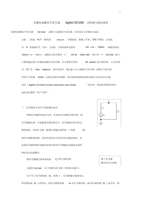
⒈ 信号源显示电压与实际输出电压理想信号源的内阻应为零。
若实际信号源的内阻为零,则信号源输出端一旦短路或负载电阻过小,信号源就会因功率过载而损坏。
实际信号源一般都在其输出端串接一个电阻R s,使信号源既使短路,在短时间内也不会因功率过载而损坏,由此使信号源的保护电路有时间实现对信号源输出电路进行保护,同时发出过载警告。
称信号源输出端串接电阻R 为信号源内阻。
图 1 信号源s输出电压示意图安捷伦 33120A (以下简称为信号源)的内阻为50 Ω。
由于有了信号源内阻 R s,如图 1 ,信号源输出端的电压,即负载电阻 R L上的电压,是信号源的电源E s在信号源内阻R s和负载电阻 R L上的分压,即V o≠E s。
信号源内设置了两个负载电阻值,开机时默认为R LD =50 Ω,通过操作可修改为R LD →∞。
在信号源开机默认为R LD =50 Ω时,信号源内部的电压源输出的电压为E s,信号源显示屏上显示的电压是V DisplayRLD1Es( 1 )R s R LDE s2若实际负载不是50 Ω,那么负载上实际得到的电压V o为V o R L E s 1E s( 2)R s R L2即信号源显示屏上显示的电压与负载上得到的实际电压不一样,V o≠V Display。
训练过程accuracy实现代码

训练过程accuracy实现代码训练过程accuracy实现代码在机器学习中,accuracy(准确率)是评估模型性能的重要指标之一。
在训练过程中,我们需要实时监测模型的accuracy,以便及时调整模型参数,提高模型性能。
下面是一个简单的Python代码示例,用于实现训练过程中accuracy的计算。
首先,我们需要导入必要的库和模块:```import numpy as npimport tensorflow as tf```接下来,我们定义一个函数,用于计算accuracy。
该函数接受两个参数:预测值和真实值。
预测值是一个二维数组,每一行代表一个样本的预测结果,每一列代表一个类别的预测概率。
真实值是一个一维数组,每个元素代表一个样本的真实类别。
```def accuracy(predictions, labels):return (100.0 * np.sum(np.argmax(predictions, 1) == labels) / predictions.shape[0])```在该函数中,我们首先使用np.argmax函数获取每个样本的预测类别。
该函数返回一个一维数组,每个元素代表一个样本的预测类别。
我们使用该数组和真实类别数组进行比较,得到一个布尔数组。
该数组的每个元素代表一个样本的预测结果是否正确。
最后,我们使用np.sum 函数计算正确预测的样本数,并除以总样本数,得到accuracy。
在训练过程中,我们可以使用该函数计算每个batch的accuracy,并输出到控制台或日志文件中。
下面是一个示例代码:```batch_size = 128num_steps = 10000graph = tf.Graph()with graph.as_default():# 定义模型# ...with tf.Session(graph=graph) as session:# 初始化变量# ...for step in range(num_steps):# 获取一个batch的数据# ...# 训练模型# ...# 计算accuracyif (step % 100 == 0):feed_dict = {tf_train_dataset : batch_data, tf_train_labels : batch_labels}predictions = session.run(train_prediction,feed_dict=feed_dict)acc = accuracy(predictions, batch_labels)print("Step %d, accuracy %.1f%%" % (step, acc))```在该代码中,我们首先定义了模型的计算图。
FG-52 5MHz FUNCTION GENERATOR 使用说明书

USER'S MANUAL5MHz FUNCTION GENERATORFG-52FG-53 is using FG-52 USER MANUAL1.FG-53 operation is similar to FG-52. Thus, FG-53 uses FG-52manual temperately.2.The only difference of FG-53 is changing FG-52 DC OFFSETOUTPUT to very useful voltage amplify function.3.When FG-53 is using as a voltage amplifier, the input signal less≦than +/-5Vp-p (+/- 5Vp-p), Max output is able to +/-20Vp-p.Bandwidth: DC ~ 5MHz, Max Current: 40mA.4.FG-53 is able to use AMPLE knob to adjust Gain to 10 times. Italso can use DC offset knob to adjust DC bias voltage. FG-53 isa very useful model for amplifying small signals experiments.I. NOTICE BEFORE OPERATION1.Unpack the instrument :After receipt of the instrument, immediately unpack and inspect it for any damage which might have been sustained when in transportation or shortage of accessories. If any sign of damage and shortage of accessories are found, immediately notify the dealer.2.Environments :Normally, operational temperature of the instrument is 10ºC to 40ºC (50ºF t o 104ºF ) . Operation of the instrument outside of this temperature range may cause damage to the circuits.Do not use the instrument in a place where strong magnetic or electrical field exists.Such fields may disturb the measurement.3.Check the Line V oltage :The instrument can operate on any one of the line voltages shown in the below table byinserting the line voltage selector plug in the corresponding position on the rear panel.Before connection the power plug to an AC line outlet, be sure to check that voltageselector plug is set in the correct position corresponding to the line voltage.CAUTION : The instrument may not properly operate or may be damage if it is connected toa wrong voltage AC line. When line voltages are changed, replace fuses also a required.Hints for operation the instrument observe the following suggestions forsuccessful instrument operation.1.Never place heavy objects on the instrument.2.Never place a hot soldering iron on or near the instrument.3.Never insert wires, pins or other metal objects into ventilation fan.4.Never move or pull the instrument with power cord or probe cord.Especially never move instrument when power cord or signal probe isconnected to a circuit.5.If the instrument is used in a manner not specified by the manufacturer,the protection provided by the equipment may be impaired.WARNING : The following precautions must be observed to help prevent electric shock.1.When the instrument is used to make testing. There is always a certainamount of danger from electrical shock. The person using the instrument insuch condition should be a qualified electronics technician or otherwise trainedand qualified to work in such circumstance.2.Do not operate the instrument with the cover removed unless you are aqualified service technician.3.The ground wire of the 3-wire Ac power plug places the chassis andhousing of the instrument at earth ground. Use only a 3-wire outlet,and donot attempt to defeat the ground wire connection or float the instrument. todo so may pose a great safety hazard.4.Do not obstruct the ventilation holes in the rear panel. As this willincrease the internal temperature.5.Never apply external voltage to output BNC of the instrument.6.Excessive voltage applied to the input BNC may damage the instrument.II.FG-52 GENERALDESCRIPTION :The FG-52 is a super deluxe function Generator combined a 5 digits, high resolution 60MHz counter.The FG-52 is a rugged, easy to operate, excellent heat dissipation and high stability instrument.The FG-52 is 4 in 1 instrument. It can be used as the following describes 4 kinds of electronic instrument respectively.1.To be as Function Generator :8 wave forms selected by rotary switch instead of push-button to prevent mis-touch or badconnection. Max. output 20Vp-p (Non-load),and Mini. output 0.1Vp-p (Non load).2.To be as Pulse Generator :FG-52 provide positive pulse and reverse negative pulse output by Pull Reverse Switch, Max.output 20Vp-p (Non-load).Frequency display by LED, pulse width from 0.4sec to 100ns.Can meet most of Audio,Video and other Basic electronic application requirement.3.To be as Sweep Generator :FG-52 provide linear sweep or log sweep selection switch to select the sweep mood. Max.sweep width1:100 and sweep speed 5sec to 10ms. Also FG-52 provide VCF input and synchronous Output Function. Convenient to operate.4.To be as counter :FG-52 is a 5 digits micro-control counter. FG-52 provide Auto range, Auto gate time and high resolution- 0.001Hz, High input impedance -1MΩ, High band width - 0.2Hz ∼ 60Mhz, High voltage resistance-150Vp-p features, Also, FG-32 provide Adjustable Trigger +/- 2.5V with LED indicate.Display unit Auto - indicate, HF / LF selector, 100Khz filter.5.To be as Dry Battery :FG-52 provide a DC Output function. The output voltage from +10V to -10 continuous adjustable.Can be used as a low power DC source. Dry Battery.III.FG-52 SPECIFICATIONS1.General Specifications :Generator -Frequency : 0.05Hz ∼ 5MHz display by 5 digits LED, Max. resolution 0.001Hz in 8 ranges.Wave form output : Sine, Square, Triangle, Positive , Ramp, Negative Ramp, Positive Pulse andNegative Pulse, DC 8 wave forms.Stability : 0.1% ∼15 minutes after switch "ON", 0.2% ∼ 24hrs after switch "ON".DC offset : +/- 10V(No. Load ), +/- 5V(50Ω Load), continuous adjustable, controlled by a offset switch.Counter -Display : 5 digits 0.36" red LED.Max. Resolution - 0.001HZ.Display unit : Hz / KHz Automatically controlled by CPU.Common Specification -Limits of operation : 0℃ ∼ 40℃, 10% ∼ 80% R.H.Storage environment : -20℃ ∼ 70℃, 0% ∼ 90% R.H.Power consumption : 25W.Power source :AC 115V (+/- 10%) 50/60Hz, FUSE : 600mAAC 230V (+/- 10%) 50/60Hz, FUSE : 300mAVentilation : DC 12V / 100mA Fan.Dimensions : 275 x 90 x 300mmWeight : 2.5Kgs Net.Accessories : Power cord, operation manual.2.Triangle wave :Frequency : 0.05Hz ∼ 5MHz, 5 digits LED display, Max. resolution 0.001HzSymmetry : 50% (Rise wave) to 50% (Fall wave), < 1%, 1Hz ∼100KHzLinearity : < 1%, (1Hz ∼100KHz).3.Sine Wave :Frequency : 0.05Hz ∼ 5MHz, 5 digits LED display, Max. resolution 0.001Hz.Distortion : < 1%, 1Hz ∼100KHz.Harmonic ratio : < 30dB, 100KHz ∼ 5MHzFrequency response : < 0.1dB, up to 100KHz., < 1.5dB, 100KHz to 5MHz.4.Square wave :Frequency : 0.05Hz ∼ 5MHz, 5 digits LED display, Max. resolution 0.001Hz.Symmetry : 50% (Positive half) to 50% (Negative half). < 1%, 1Hz ∼100KHz Rise time : < 90ns (20Vp-p , No load).5.Ramp wave :Frequency : 0.05Hz ∼ 4.5MHz, 5 digits LED display, Max. resolution 0.001Hz,8 range selected by rotary switch.Symmetry : 90% (Rise wave) to 10% (Fall wave), continuous adjustable.Linearity : < 1%, (0.1Hz ∼100KHz).6.Positive pulse :Frequency : 0.05Hz ∼4.5MHz, 5 digits LED display, Max. resolution 0.001 Hz. Width : 0.4sec ∼100ns, continuous adjustable.Symmetry - 1:1 to 10:1 continuous adjustable. 1Hz ∼100KHz.Reverse : Pull the Rev, switch, the output will becomes Negative Pulse.7.DC :Output voltage : +10V to -10V continuous adjustable by OFFSET switch.8.Main output :Output impedance : 50Ω, < 2%Max. Output : 20Vp-p (Non-load), +/- 1Vp-p., 10Vp-p (50Ω load) +/- 0.5V.Min. Output : 0.1Vp-p (Non-load), or 0.05Vp-p (50Ω load)Attenuator : One -26dB (1/20) Attenuator, < 2% Accuracy9.Synchronous Output :Output impedance : 50Ω, < 2%, Accuracy.Output level : TTL level, > 3Vp-p fix amplitude.Fan out : > 20Rise time : <60nS.10.VCF input :Input impedance : 0 ∼10VInput frequency : DC ∼1KHzInput frequency variety - 1:1 to 1:10011.Sweep synchronous output :Output impedance : 1KΩ, < 2%Output wave form : Linear or log sweep ramp wave.Output amplitude : 10Vp-p (Non load) or 5Vp-p (1KΩ load) Output frequency : 0.2Hz ∼100Hz continuous adjustable.12.Sweep generator :Sweep form : Linear or log switchable.Sweep speed : 5sec ∼10ms, continuous adjustable.Sweep width - 1:1 ∼1:10013.Counter :Display : 5 digits, 0.36" RED LED display.Max. Resolution : 0.001HzDisplay unit : Hz / KHz Auto range.Time base : 20MHzTemperature coefficient : < 20ppm/ ºCAccuracy : < 0.02% +/- 1 digit.Power supply : +5V, 160mAInternal counter -Range :Auto range with 4 resolution,0.001Hz / 0.01Hz / 0.001KHz / 0.01KHz, Auto control by CPU.Display : 0.500Hz ∼ 5000.0KHz A u t o select by CPU.Gate time : Variable, 0.25sec ∼5sec, Auto - setting.Min. Display digits : 4 digits.External counter -Max. Input voltage : < 150VrmsInput impedance : 1MΩ, < 2%Input frequency : 0.2Hz ∼60MHzCoupling :HF - For 100KHz up frequency.LF -- With 100KHz filter, for the frequency lower than 100KHzMin. display digits : 4 digits.Gate time : 0.25sec ∼10sec, Auto - setting depends on the input frequency Sensitivity : > 30mVrms (1MHz)IV .FG-52 FRONT PANEL DESCRIPTION1.POWER SWITCH - Push the switch "ON" will light the LED of the digits (14) to indicate power "ON".2.FREQUENCY - Turn the switch to set the desired frequency generated. This knob is for micro – adjust.3.SYNCHRONOUS OUTPUT - The BNC synchronous output the TTL level square wave signal, the output frequency as MAIN output.4.SWEEP OUTPUT - Sweep signal output BNC. It will operate individually whether the instrument was under sweep mode operation or not, Out put impedance 1k Ω, output amp. 10Vp-p, output signal : Linear or Log.5.MAIN OUTPUT - Function wave signal output BNC, Max. output impedance 50Ω Max. amplitude 20Vp-p (Non load).6.AMPLITUDE - Turn the switch to adjust the output signal amplitude. Pull out the switch to attenuate the output 20 times (or -26dB).7.DC OFFSET - The switch will set at OFF position in normal operation. When use for BIAS circuit, pull "ON" the switch and turn to adjust DC offset voltage.8.SWEEP RATE - Turn the switch to adjust the sweep rate from 5sec to 10mS and the signal will output from (4). When pull the switch, the signal will synchronous output from (4) and (5).9.SWEEP WIDTH - The switch will effected only under switch (8) was "ON". Turn the switch to adjust the sweep width. In normal position. It is " Linear sweep " and it will be under " Log sweep " when pull out the switch.10.FUNCTION WA VE SELECTOR - Turn the switch to select the output wave forms. Sine, Triangle,Square, DC, 4wave forms.11.FREQUENCY RANGE - Turn the switch to set the frequency of the output signal. The frequency display on (14) will beas the product of the indicated digits by (2) and (11). The frequency will be 10 times difference on each step.x1, x10, x100, x1000 4ranges.---------------------------------------------------------------------------------------------------------------------------------------------------------1 2345678 9111012191817161514 1312.Hz - the LED lit means the display units are "Hz".13.KHz - the LED lit meas the display units are "Khz".14.LED DIGITS - 5 digits to indicate frequency generated or EXT input. The units will be indicated by (12) or (13) selected by CPU automatically.15.EXT-COUNTER - The red LED indicate Ext. counter condition. LED Light - Trigger level too high. LED Dark - Trigger level too low. LED flash - Triggering state.16.DISPLAY - Indicate the source of the frequency display by (14).INT Hz / KHz -- Display the frequency of the signal generated by the FG-52.EXT HF - Display the external input high frequency signal, Set at this position to strain out DC signal and low frequency harmonic signal. Input only the expected high frequency signal.EXT - LF 100KHz Filter - Display the external input low frequency signal, Set at this position to strain out the signal higher than 100KHz make the low frequency signal more stable.17.RAMP / PULSE - Turn this switch to display RAMP wave from Tri wave and display PULSE from squ wave. When at pull Invert position, The display will be negative Rampand negative Pulse.18.EXT-INPUT - External signal input BNC. The input frequency 0.2Hz to60MHz, Max. input voltage 150Vrms (when (17) was at"PULL" position).19.VCF-INPUT - External input DC signal to control the frequency generated. External input AC sweep signal to make it as External sweep. External input AC sine wave to make it as external FM modulation. Input signal 0 ∼10V, < 1KHz. Input impedance 1KΩ.V . FG-52 OPERATION INSTRUCTIONSWARNING : Before applying power to your FG-52, make sure that the input voltagesetting is correct for your power source.CAUTION : All the knobs are set at " PUSH " position on operation if not specialmarked to be set at " PULL ".(A). Function Generator and Inspection ( Ref. to Fig.9-1)1.Push the power switch on and make sure that the LED of the 5 digits are lit.2.Connect OUTPUT BNC of FG-52 to the CH1 input BNC of your Oscilloscope, and the SYNC OUTPUT BNC to CH2, and set the trigger source of your oscilloscope at CH2.3.Turn the FREQUENCY knob from x0.05 ∼ x5.0 You will find the display of 5 digits LED and oscilloscope will be changed slightly on each step.4.Turn the RANGE knob from x1 ∼ x1000. You will find the display of 5 digits LED value will change 10time on each step and the oscilloscope too. And then see (7) switch at Hz or KHz the display value will be changed to x 1 or x 1000 too.5.Turn the FUNCTION knob to select the wave form output to CH1 of your Oscilloscope. CH2 will be TTL square wave only.6.Turn the AMPL knob to adjust the amplitude of the signal output to CH1, and when " PULL " out the switch, the amplitude will be reduced 20 times ( -20dB) but the display of CH2 (Sync output signal) will keep unchanged.7.Turn the OFFSET knob. You will find both CH1 and CH2 will not changed.This switch will operated only at " PULL " position. PULL out the offset switch and turn to set DC offset voltage (from +10V to -10V) of the main output signal. But the sync output signal will not affected.Note : When the offset voltage are higher then the wave (+ or -) the display wave form will be cut OFF.------------------------------------ 6-------- 213745(B). SWEEP GENERATOR (Ref. to Fig 9-2)1.Switch on the FG-52 and lit the 5 digits LED.2.Connect the main OUTPUT BNC to the CH1 input BNC of you Oscilloscope.3.Connect the SWEEP OUTPUT BNC to the CH2 input BNC of your Oscilloscope and set the trigger source of the oscilloscope at CH2.4.Turn the SWEEP RATE knob, the CH2 of the oscilloscope will display a linear saw - tooth wave, the frequency will be variable from 5sec to 10mS by turn the switch. CH1 will display the wave according to theFUNCTION switch position. PULL out the switch to set "SWEEP ON". the display of CH2 will keep unchange d , the display frequency will be variant by turn the knobs. But the display of CH1 will be sweep wave, and the sweep speed will depend on the sweep rate.NOTE : After "PULL SWEEP ON", the trigger source of the oscilloscope must be changed from CH2 to CH1.5.Turn the SWEEP WIDTH knob to adjust the sweep width by the display of CH1.NOTE :Be sure that the SWEEP RATE SWITCH was at " PULL " position.When PULL out the sweep width switch, the sweep mode will changed from linear to log sweep. The wave form display of CH1 will becomeslog form.6.AMPL and FUNCTION knobs will operate as Generator.7.Frequency display on 5 digits LED as Generator, before "PULL SWEEP ON".this frequency will be the start frequency. After "PULL SWEEP ON", the sweep condition include frequency, wave form and sweep mode etc. will be observed from the CRT of the Oscilloscope. The display on LED will continuous variety.------------------------------------------------------- 7 5 4 618 328.VCF INPUT - Set the sweep rate switch at "PUSH" position to set FG-52 at normal generator mode. connect the sweep output BNC to VCF INPUT BNC and check the wave form display on the scope CH1. the wave form display would be the sweep wave. When input a sine wave from an other generator to VCF INPUT to observe the FM display. Be sure the frequency of the basic wave (FG-52) are higher than the external input signal.(C ). PULSE wave Generator (Ref. to Fig.9-3)1.Push the power on and lit the 5 digits LED.2.Connect the main output to CH1.3.Connect the SYNC output to CH2 and set the trigger source of the Oscilloscope on CH2.4.Set the FUNCTION knob on Squwave position, and turn knob till the display become pu l se wave form you want.5.Set the FREQUENCY and RANGE to the desired frequency display on LED.6.Pulse width : th e pulse width can be adjustable by knob .7.Pull knob to display negative pulse position and test the negative pulse as positive pulse.8.Turn the AMPL to adjust the amplitude of the signal output from the main output BNC.The signal will be -26dB when " PULL " out the switch. But the signal output from " SYNC " output BNC will not affect by this switch. T he output signal of " SYNC " output will keep on TTL level.9.Set the DC offset voltage by pull out the " OFFSET " switch and turn to a djust the DC offset voltage from +10V to -10V.--------------------------------------------------------------549 8156 732(D)Frequency counter (Ref. to Fig. 9-4)1.Switch on the power switch, lit the LED digits.2.DISPLAY : The coupling provide 4 steps.(a). INT/Hz : to be used as internal counter from 0.05Hz~5000Hz. (b). INT/KHz : to be used as internal counter from 0.5KHz to 5MHz.(c). EXT HF : To use as External Counter for high frequency (100KHz to 60MHz). (d). EXT LF : To use a External counter for low frequency (0.2Hz ∼100KHz).3.Connect the EXT INPUT BNC to the external signal source, lit the LED 4.Display unit : The display unite of the FG-52 will be on Hz or KHz automatically controlled by CPU.-----------------------------1 234。
AFG2021-SCArbitrary Function Generator 数据手册说明书
159045400Arbitrary Function GeneratorAFG2021-SC DatasheetThe AFG2021-SC Arbitrary Function Generator gives you the power to create the signals you need at an entry-level price. With 20 MHz bandwidth,14-bit resolution, and 250 MS/s sample rate, you can generate all manner of signals -- from complex serial data streams to simple audio frequencies or clock signals to the output of an airbag sensor during a crash. With 9 standard waveforms, modulation capability, and a built-in noise generator, you can quickly create the signal you need to thoroughly exercise your designs.Key performance specifications20 MHz sine, 10 MHz pulse waveforms provide coverage for your mostcommon applications250 MS/s sampling rate and 14-bit vertical resolution enable the creation of high-fidelity signalsKey featuresThe innovative UI reduces setup and evaluation time with direct accessto frequently used functions and parametersThe internal 4 × 16 kS memory and the USB memory expansioncapability provide substantial capacity for defining complex waveforms USB host port on front panel for saving/reloading arbitrary waveformsand instrument settingsBuilt-in Modulation, Noise Generator, Burst, and Sweep modes forgreater versatilityBuilt-in waveforms provide quick access to commonly used signals Large 3.5 inch color screen displays both graphical and numericwaveform information simultaneouslyMenu and online help in Simplified Chinese and English2U height and half-rack width fits benchtop applicationsFree ArbExpress software makes waveform editing extremely easyApplicationsElectronic test and designSensor simulationEducation and training Functional testSuperior performance at an affordable priceMost electronic devices, circuits, and systems are designed to handle some form of a signal. These signals can be simple like an audio frequency or clock signal or more complex like a serial data stream or the output of an airbag sensor during a crash. With 20 MHz bandwidth, 14-bit resolution,and 250 MS/s sample rate, the AFG2021-SC Arbitrary Function Generator can create both simple and complex signals at an entry-level price. With 9 standard waveforms, 25 built-in application waveforms, modulation capability, and a built-in noise generator, you can quickly create the signal you need to thoroughly exercise your designs.Intuitive user interfaceThe innovative ease-of-use features first seen on the AFG3000 Series arbitrary/function generators are the building blocks for the AFG2021-SC,providing quick access to setup and operational features. Experienced AFG3000 users will find it especially easy to set up the new AFG2021-SC.A 3.5 inch color TFT screen shows relevant parameters in both graphic and text formats, so you can have full confidence in your settings and focus on the task at hand. The front-panel shortcut buttons and rotary knob providequick access to the most frequently used functions and settings. 1Excellent frequency agilityTraditional function generators created their output signals using analog oscillators and signal conditioning. The Tektronix AFG2021-SC relies on Direct Digital Synthesis (DDS) techniques. DDS technology synthesizes waveforms by using a single clock frequency to generate any frequency within the instrument’s range. DDS architecture provides exceptional frequency agility, making it possible to program fast frequency and phase changes, which is useful for testing radio and satellite system components,amplifiers, and filters.Frequency range from 1 μHz to 20 MHz, supports a wide range of amplifier and filter testing applications.ArbExpress ® for real-world waveforms with minimal effortWith ArbExpress software, you can quickly create waveforms that can be copied to the AFG2021-SC to meet custom stimulus requirements.ArbExpress supports direct connection to Tektronix oscilloscopes and AFGs through USB, GPIB, or LAN (connection type is model dependent).The software allows you to import real-world signals captured with an oscilloscope onto a PC, then edit and copy them onto an AFG through a USB memory device to duplicate the captured waveform. This is extremely useful for automotive, medical, and industrial applications where recreatingsensor output is critical to analyzing the integrity of the design.ArbExpress software helps you easily duplicate real-world signals.ConnectivityUsing the front-panel USB host port, you can save your customized waveforms or instrument settings onto a USB memory device. Reloading the data is easily done by plugging the device back into the USB host port.Compact form factorThe 2U height and half-rack width form factor allow the AFG2021-SC to be stacked on other bench instruments, such as digital multimeters, power supplies, and frequency counters, saving valuable bench space.Datasheet2 Arbitrary Function Generator -- AFG2021-SCSpecifications 1All specifications are guaranteed unless noted otherwise.Model overviewGeneral characteristicsSine wave 1 μHz to 20 MHzSine wave in Burst Mode 1 μHz to 10 MHz20 MHzEffective maximum frequencyoutAmplitude flatness (1 V p-p)<5 MHz±0.15 dB (±0.05 dB, typical)5 MHz to 20 MHz±0.3 dB(±0.02 dB, typical)Harmonic distortion (1 V p-p)10 Hz to 20 kHz<-70 dBc (<-77 dBc, typical)20 kHz to 1 MHz<-60 dBc (<-72 dBc, typical)1 MHz to 10 MHz<-50 dBc (<-55 dBc, typical)10 MHz to 20 MHz<-40 dBc (<-55 dBc, typical)THD<0.2% (<0.15%, typical) 10 Hz to 20 kHz, 1 V p-pSpurious (1 V p-p)10 Hz to 1 MHz<–60 dBc (<–71 dBc, typical)1 MHz to 20 MHz<–50 dBc (<–68 dBc, typical)Phase noise, typical20 MHz: <–110 dBc/Hz at 10 kHz offset, 1 V p-pResidual clock noise–63 dBmSquare wave 1 μHz to 10 MHzRise/fall time≤18 nsJitter (RMS)<500 ps (<60 ps, typical)Ramp wave 1 μHz to 200 kHzLinearity≤0.1% of peak output at 10% to 90% of amplitude rangeSymmetry0.0% to 100.0%1The given typical values are not warranted. But 80% or more manufactured units will perform to the level indicated at room temperature (approximately 25 °C). 3Pulse wave1 mHz to 10 MHz Pulse width 30.00 ns to 999.99 s -- Resolution 10 ps or 5 digitsPulse duty 0.001% to 99.999% (Limitations of pulse duty width apply)Edge transition time 18 ns to 0.625 × Pulse Period -- Resolution 10 ps or 4 digitsLead delay -- Range Continuous Mode: 0 ps to Period Trigger/Gate Burst Mode: 0 ps to Period – [Pulse Width + 0.8 × (Leading Edge Time + Trailing Edge Time)]-- Resolution 10 ps or 8 digits Overshoot <5%, typicalJitter (RMS)<500 ps (<90 ps, typical)Other waveforms 1 μHz to 200 kHz Noise bandwidth (-3 dB)20 MHz Noise type White Gaussian DC (into 50 Ω)–5 V to +5 V Arbitrary waveforms1 mHz to 10 MHz Arbitrary waveforms in Burst Mode1 mHz to 5 MHz Effective analog bandwidth 34 MHz Nonvolatile memory 4 waveforms Memory: sample rate2 to 16 k: 250 MS/s Vertical resolution 14 bits Rise/fall time ≤20 ns Jitter (RMS) 4 nsAmplitudeRange50 Ω load: 1 mV p-p to 10 V p-p Open circuit: 2 mV p-p to 20 V p-pAccuracy ±(1% of setting + 1 mV), (1 kHz sine waveform, 0 V offset, >10 mV p-p amplitude)Resolution 0.1 mV p-p , 0.1 mV rms , 1 mV, 0.1 dBm, or 4 digits Units V p-p , V rms , dBm (sine wave only)Output impedance 50 ΩLoad impedance setting Selectable: 50 Ω, 1 Ω to 10.0 kΩ, high Z (adjusts displayed amplitude according to selected load impedance)Isolation<42 V peak maximum to earthShort-circuit protection Signal outputs are robust against permanent shorts against floating ground External voltage protectionTo protect signal outputs against external voltages use fuse adapter 013-0345-00DatasheetGeneral characteristics4 DC offsetRange50 Ω load: ±(5 V peak – amplitude V p-p /2)Open circuit: ±(10 V peak – amplitude V p-p /2)-- Accuracy ±(1% of |setting| + 5 mV + 0.5% of amplitude (V p-p ))-- Resolution1 mVModulation characteristicsAM, FMCarrier waveforms All, including ARB, except pulse, noise, and DC SourceInternal/externalInternal modulating waveform Sine, square, ramp, noise, ARB (AM: maximum waveform length 4,096; FM: maximum waveform length 2,048)Internal modulating frequency 2 mHz to 50.00 kHzAM modulation depth 0.0% to +120.0%Min FM peak deviation DC Max FM peak deviation 10 MHzPulse width modulationCarrier waveform Pulse SourceInternal/externalInternal modulating waveform Sine, square, ramp, noise, ARB (Maximum waveform length 2,048)Internal modulating frequency 2 mHz to 50.00 kHzDeviation 0% to 50.0% of pulse periodSweepWaveforms All, including ARB, except pulse, noise, and DC Type Linear, logarithmic Sweep time 1 ms to 300 s Hold/return time0 ms to 300 s Max total sweep time (Sweep + hold + return)300 s Resolution1 ms or 4 digits Total sweep time accuracy,typical0.4%Min start/stop frequencyAll except ARB: 1 μHz ARB: 1 mHzMax start/stop frequencySine: 20 MHz Square: 10 MHz ARB: 10 MHz Others: 200 kHzBurstWaveforms All, including ARB, except noise and DC TypeTriggered, gated (1 to 1,000,000 cycles or infinite)Internal trigger rate 1 μs to 500.0 sGate and trigger sourcesInternal, external, manual trigger Arbitrary Function Generator -- AFG2021-SCGeneral characteristics 5DatasheetAuxiliary input characteristicsModulation inputInput range±1 V full scaleImpedance10 kΩFrequency range DC to 25 kHz (122 kS/s sample rate)External triggered/gated burstinputLevel TTL compatiblePulse width100 ns minimumSlope Positive/negative selectableTrigger delay0.0 ns to 85.000 sResolution100 ps or 5 digitsJitter (RMS), typical Burst: <500 ps (Trigger input to signal output)10 MHz reference inputImpedance 1 kΩ , AC coupledRequired input voltage swing100 mV p-p to 5 v p-pLock range10 MHz ±35 kHzAuxiliary output characteristicsTrigger outputLevel Positive TTL level pulse into 1 kΩImpedance50 ΩJitter (RMS), typical500 psMax frequency 4.9 MHz (4.9 MHz to 20 MHz: A fraction of the frequency is output)System characteristicsFrequency setting resolution 1 μHz or 12 digitsPhase (except DC, Noise, Pulse)Range–360° to +360°Resolution Sine: 0.01°Other Waveforms: 0.1°Internal noise add When activated, output signal amplitude is reduced to 50% Level0.0% to 50% of amplitude (V p-p) settingResolution1%Main output50 ΩInternal frequency responseStability All except ARB: ±1 ppm, 0 °C to 50 °CARB: ±1 ppm ±1 μHz, 0 °C to 50 °CAging±1 ppm per yearPower source100 V to 240 V, 50 Hz to 60 Hz or 115 V, 400 Hz6 Power consumption60 WWarm up time, typical20 minutesPower on self diagnostics, typical<10 sAccoustic noise, typical<50 dBADisplay 3.5 in. Color TFT LCDUser interface and help language Simplified Chinese (default) and English (user selectable)Physical characteristicsDimensionsHeight104.2 mm (4.10 in.)Width241.8 mm (9.52 in.)Depth419.1 mm (16.50 in.)WeightNet 2.87 kg (6.3 lb.)Shipping 4.72 kg (10.4 lb.)EMC, environmental, and safety characteristicsTemperatureOperating0 °C to +50 °CNon-operating-30 °C to +70 °CHumidityOperating≤80%, +0 °C to +40 °C, noncondensing≤60%, +40 °C to +50 °C, noncondensing Non-operating5% to 90%, <+40 °C, noncondensing5% to 80%, ≥+40 °C to ≤+60 °C, noncondensing5% to 40%, >+60 °C to ≤+70 °C, noncondensingAltitudeOperating Up to 3,000 m (9,842 ft.)Non-operating Up to 12,000 m (39,370 ft.)EMC compliance EU Council Directive 2004/108/ECSafety UL61010-1; 2004CAN/CSA C22.2 No. 61010-1; 2004EN61010-1; 2001IEC61010-1; 2001 Arbitrary Function Generator -- AFG2021-SCSystem characteristics 7DatasheetOrdering informationModelsAFG2021-SC 1 µHz to 20 MHz sine wave, 1-channel arbitrary function generator, Simplified ChineseInstrument optionsLanguage optionsOpt. L7Simplified Chinese manualOpt. L99No manualLanguage options include translated front-panel overlay for the selected language(s).Power plug optionsOpt. A10China power plug (50 Hz)Opt. A99No power cordService optionsOpt. C3Calibration Service 3 YearsOpt. C5Calibration Service 5 YearsOpt. D1Calibration Data ReportOpt. D3Calibration Data Report 3 Years (with Opt. C3)Opt. R5Repair Service 5 Years (including warranty)Opt. R5DW Repair Service Coverage 5 Years (includes product warranty period). 5-year period starts at time of instrument purchase AccessoriesStandard accessories—User manual—Power cord—CD-ROM with Specifications and Performance Verification Technical Reference manualRecommended accessoriesRMU2U Rackmount kit013-0345-00 Fuse adapter, BNC-P to BNC-R159-0454-00 Fuse set, 3 pcs, 0.125 A.012-0482-00 BNC cable shielded, 3 ft.012-1256-00 BNC cable shielded, 9 ft.011-0049-02 50 Ω BNC terminator8 WarrantyThree-year warranty on parts and labor.Tektronix is registered to ISO 9001 and ISO 14001 by SRI Quality System Registrar.Arbitrary Function Generator -- AFG2021-SC 9DatasheetASEAN / Australasia (65) 6356 3900 Austria 00800 2255 4835*Balkans, Israel, South Africa and other ISE Countries +41 52 675 3777 Belgium 00800 2255 4835*Brazil +55 (11) 3759 7627 Canada180****9200Central East Europe and the Baltics +41 52 675 3777 Central Europe & Greece +41 52 675 3777 Denmark +45 80 88 1401Finland +41 52 675 3777 France 00800 2255 4835*Germany 00800 2255 4835*Hong Kong 400 820 5835 India 000 800 650 1835 Italy 00800 2255 4835*Japan 81 (3) 6714 3010 Luxembourg +41 52 675 3777 Mexico, Central/South America & Caribbean 52 (55) 56 04 50 90Middle East, Asia, and North Africa +41 52 675 3777 The Netherlands 00800 2255 4835*Norway 800 16098People's Republic of China 400 820 5835 Poland +41 52 675 3777 Portugal 80 08 12370Republic of Korea +822 6917 5084, 822 6917 5080 Russia & CIS +7 (495) 6647564 South Africa +41 52 675 3777Spain 00800 2255 4835*Sweden 00800 2255 4835*Switzerland 00800 2255 4835*Taiwan 886 (2) 2656 6688 United Kingdom & Ireland 00800 2255 4835*USA180****9200* European toll-free number. If not accessible, call: +41 52 675 3777For Further Information. Tektronix maintains a comprehensive, constantly expanding collection of application notes, technical briefs and other resources to help engineers working on the cutting edge of technology. Please visit . Copyright © Tektronix, Inc. All rights reserved. Tektronix products are covered by U.S. and foreign patents, issued and pending. Information in this publication supersedes that in all previously published material. Specification andprice change privileges reserved. TEKTRONIX and TEK are registered trademarks of Tektronix, Inc. All other trade names referenced are the service marks, trademarks, or registered trademarks of their respective companies.30 Jan 2016 75W-28510-4 159045400。
机电专业英语单词

Aactive circuit elements 有源电路元件active branch 有源电路alternating current 交流电amplitude (叫变量的)幅值振幅angnlar velocity 角频率 A..C.generator 交流电动机active length 有效长度anti-phase 反向accuracy 精确性准确性精度aperiodic 非周期性的approach 接近途径approximation 接近值arbitrary 任意的algorithm 算法alternative 替换的交替的比较方案a good-quality voltmeter 高质量的电压表Bbio-polar junction transistor双极性晶体管buffer amplifier 缓冲放大器Ccircuit components 电路元件circuit parameters 电路参数conductor 导体conductance 电导circuit diagram 电路图carbon-filament lamp 碳丝电灯circuit branch 支路complex circuit 复杂支路communication circuit 通信电路common base 共基极common collector 共集电极common source 共源极common drain 共栅极channel 信道频道coefficient 系数convergence 收敛conversely 相反的逆的coordinate 坐标criterion 标准规范decaying oscillatory function 衰减震荡函数cascade 串联串级constancy 不变恒定corresponding to 符合于Ddirect-current(D.C)circuit 直流电路displacement current 位移电流double subscript 双下标D.C machine 直流电机definition 定义distribution of B 磁场分布D.Cblocking capacitor 直流耦合电容器 D.C supply 直流供电电源dimension 维数Differentiate 求…的微分Dirichlet 狄里克雷条件discontinuity 心电图心动电流图Dead-hand 死区deem 认为认定diagram 图表简图Diagrammatically 利用图表dead-weight tester 净重测量仪Eelectrical device 电气设备electrical energy 电能energy source 能源energy converter 电能转换器 e.m.f 电动势external characteristic 外特性electrical-sheet stel 电工钢步epoch angle 初相角electrode 电极电焊条emitter 发射器发射机emitter follower 射极跟随器even 偶数的expansion 展开(式)FFrequeney 频率field effect transistor 场效应管foregoing前述的在前的Faithful 可靠的正确的GGenerator 发电机gain增益geometrical 几何学的Geometry 几何学HHeating applicance 电热器heat-treatment 热处理器harmonic current 正弦电流Hybrid-πmodel混合π型模型half-wave symmetry 半波对称harmonical 谐波的Harmonic 谐波hysteresis 滞后hysteresis over 滞后误差IIdeal source 理想电源ideal voltage source 理想电压源ideal current source 理想电流源Internal resistance 内阻instant of time 瞬时instantaneous value of current 电流瞬时值Induction-heading 感应发热initial phase 初相角in quadrature 正交In phase 同相insulator 绝缘体in parallel with 与…并联Isolation 隔离绝缘隔振input resistance 输入电阻identity 恒等式Instant 瞬时瞬间integrand 被积函数integrate 求…的积分Intuitively 直观的直觉的intermittently 间歇的JKLLoad characteristic 负载特性load resistance 负载电阻leakage current 漏电流Lag in phase behind (相位)落后Legendre 勒让德多项式linear 线性的Locus 轨迹linearity 线性度MMagnetic and electric field 直磁场metal-filament lamp 金属丝灯泡mechanical strength 机械强度Modulated by (由…)调制magnetic pole 磁极magnetic induction 磁感应强度Mid-frequency band 中频带main 电源电力网manifestation 表现Minimum 最小是最小化mutually 相互地mapping 映射Momentum 要素magnification 放大放大倍数measurand 被测量Measuring system deemed by expert 由专家认定的测试系统NNon-linear characteristics 非线性特性non-salient pole 隐(非凸)极notation 符号记号Negligible 可忽略的OOhm’s low 欧姆定律over-voltage 过电压output resistance 输出电阻Odd 奇数的单数的ohm 欧姆order 次序阶Origin 原点orthogonal 正交的直角的occasion 时机机会场合Offset 便宜oscilloscope 示波器PPrimary cell 原生电池passive element 无源原件P.D=potential drop 电压降passive circuit elements 无源电路元potential distribution 电位分布period 周期power transmission line 输电线periodic current 周期电流pole-pairs 极对数position reference direction 正(参考)方向peak value (交变量)最大值phase 相位pulsatance 谐振常数角频率phase shift 相位移polarity 极性偏极paralled circuit 并联电路paralled resonance 并联混振paralled series 混联peak 最高的最高峰periodicity 周期perpendicular 垂直的正交的polynomial 多项式的多项式power series 幂级数performance 特性precision 精确度put…away 拿开送走QQuasi-periodic 准周期的Rreceiving end 接收端reference point 参考点remote control 遥控rotor 电机转子radian 弧度rectifier 整流器resistor 电阻器reinforce 加强reproducibility 可再现性resolution 分辨率Ssecondary cell 再生电池self/mutual induction 自/互感storage battery 蓄电池series and parallel equipment circuit 串并联等值电路single-loop network(circuit)单回路网络(电路)symbolized by 用符号表示semiconductor oscillator 半导体振荡器stator 电机定子slip-ring 滑环source follower circuit信号跟随电路steaked up 叠装small signal amplifier 小信号放大器self-bias resistor 偏置电阻slot 槽series 展成级数级数set 集合sinusoidal 正弦的susceptible 敏感的易受影响的symmetry 对称symmetrical 对称的shift operator 移位算子shifting property 筛选特性static friction 静态摩擦sensitivity 灵敏度span 范围tolerance 公差Ttime-invariant 时不变的the dielectric 电介质terminal voltage 端电压term 术语项theorem 定理法则time domain 时域trigonometric 三角法的trigonometric identities 三角恒等式trajectory 轨道truncate 截断截断的Uunidirectional current 单方向电流underlying 基础的在下面的Vvoltage drop 电压降volt-ampere characteristics 伏安特性vector 向量矢量vice versa 反之亦然vicinity 附近Wwire 导线Walsh function 沃尔什函数XYZ。
OscilloscopeAndFunctionGeneratorForThePC.pdf

Oscilloscope and Function Generator for the PCtest equipment with Centronics interfaceReview by Harry BaggenMany readers are undoubtedly familiar with the company name Velleman, because of their electronics kits. Their range of products encompasses a wider range however; several different types of test equipment are also available. We subjected two such instruments to closer scrutiny: a digital storage oscilloscope and a function generator for the PC.examine a couple of instruments a little bit closer.The equipment under evaluation is a Function Generator PCG10(also available as kit K8016) and a Digital Storage Oscilloscope PCS500(a single-channel version comes as kit K8031). Both instruments are intended for use in conjunction with a PC. Consequently,they are not much more than small grey boxes with a few connectors. Operation and read-out takes place entirely on the computer display. For this purpose, both devices are fit-ted with an optically isolated Centronics interface. I n order to be able to use both instruments at the same time (which is rather likely) the function generator is fitted with a pass-through connector, so that both devices can be connected to a single Centronics port.First, the most important specifications:PC Function Generator PCG10- frequency range 0 to 1MHz- direct digital synthesis (DDS) with 32k waveform-memory, sampling frequency 32MHz- accuracy of selected frequency: 0.01%- output amplitude: 0.1 to 10V pp (50Ωoutput impedance)- offset adjustment –5 to +5V - waveform resolution: 8 bits- waveforms: sine, square, triangle and user-defined- output filter can be deactivatedDigital Storage Oscilloscope PCS500- time base 100ms to 10ns/div - input sensitivity 5mV to 15V/div - sampling frequency 50MHz- sampling frequency for repetitive signals:1GHz- extensive triggering capabilities (edge,level, source)- autoset and pre-trigger function- markers for time, frequency and voltage - linear or smoothed interpolation- record length 4,096 samples/channel- additional functions: spectrum analyser and transient recorder.In practiceBoth instruments were connected to a rather old Pentium PC in order to examine their capabilities in actual use. Since you need to have a spare Centronics port available, you will either have to connect the printer to the USB port, or fit an additional PCI expansion card with a second Centronics port. It is a pity that this test equipment does not make use of the USB port. This would have been much easier (perhaps a suggestion for the next generation?).As already mentioned in the intro-duction, the name Velleman is prac-tically synonymous with well thought out electronics kits dir-tributed through a wide network of electronics retailers. But the product range hasn’t been limited to kits for a considerable time now. The assort-ment is very extensive and just about anything that is remotely related to electronics can be sup-plied, from disco mirror balls to right up to advanced test equipment. It isfrom the latter category that we willFigure 1. The oscilloscope window offers all the adjustment options of a real two-channel scope.Figure 2. The spectrum analyser shows the frequency components of the input signal.The instruments may now be connected.The signal generator is connected to the PC first. Next, the oscilloscope is connected to the signal generator. All the necessary cables are supplied. Pay attention when connecting the mains adapters. The oscilloscope oper-ates from 9V and the signal generator from 12V! We didn’t dare to find out whether or not something fails if they are reversed!The accompanying PC-Lab 2000 program can now be installed. This program is com-patible with most versions of Windows and the installation on our test computer was completed without problems. Also, the most recent version can always be obtained from the Velleman website.After starting the program a setup win-dow appears. Here you have to tick the boxes for the equipment that is connected and indi-cate the address of the printer port that has been used. Once this is completed, the oscil-loscope window appears on the screen.The test cables that were supplied with the unit will suffice for an initial evaluation.However, for ‘real’ measurements we would like to suggest that you obtain some authen-tic oscilloscope probes, because the supplied test cables are not much more than a piece of cable with two croc clips.After connecting a signal and clicking the Autoset button, the ‘scope immedi-ately produced a usable picture.Both the input sensitivity and the time scale are automatically adjusted with this function, resulting in a good readable signal that is dis-played over several periods. Natu-rally, many things can also be adjusted by hand, just like the but-tons on a normal oscilloscope.Because of the storage function, sin-gle-shot signals can easily be recorded and displayed. The markers are very useful in practice, as well as the ability to display the effective value or dBm value of the signal in the oscilloscope window.The four fastest time settings,200ns/div to 20ns/div, are unfortu-nately only of limited use, because a method is used where a periodic sig-nal is sampled at different points. In this way a pseudo sampling rate of 1GHz is obtained. Note, however,that this method is only useful if the signal does not change. And who can be sure of that?Using the normal sampling fre-quency of 50MHz, the scope is usable to about 5 or 10MHz,depending on the degree of accuracy required to make a proper judge-ment of the waveform.With the click of a button, a change can be made to the spec-trum-analyser window. This pro-vides an impression of the frequency components of a signal, so that, for example, distortion components can be examined. Regrettably, there are several details that make this feature less user-friendly. The division of the frequency scale is rather strange (multiples of 3 and 12, while one would expect 3 and 10, because there are actually 10 divisions dis-played on the screen). The vertical scale is even more awkward. It can-not be changed to a logarithmic scale, which is particularly useful in an FFT plot. It is, however, possible to select a logarithmic scale for the horizontal axis. Despite all this, there are many nice features, such as the choice of FFT window and very use-ful markers (which do show the level in dB!).The transient recorder is another function that can be invoked. This is very similar to the oscilloscope win-dow, but the time scale is much longer (up to 2000s/div). This way,very slowly varying processes can be traced (more than a year is possi-ble).The measured oscilloscope sam-ples can be stored in a text file and may be retrieved later for viewing on the display.A separate window is opened for the operation of the function gener-ator. This not only provides the opportunity to adjust the output amplitude, shape and frequency, but also shows a preview of the wave-form. The controls are conveniently arranged and the frequency can be adjusted quickly with a slider or by typing in the exact value. The output amplitude and offset are adjusted in a similar manner. In addition to the three waveform buttons, there is the button ‘More funct.’ This offers a selection between sin(x)/x-function,noise, a frequency sweep and a number of waveforms from the library. With the help of a separate editor, the user can also define waveforms for themselves.Unfortunately, the frequency range of the generator is rather lim-ited; the maximum value is onlyFigure 3. The generator has several extras, such as a number of pre-programmed wave-forms, a waveform-sequencer and a waveform-editor.but also has a much lower sampling fre-quency. And finally, dear developers from Velleman, perhaps use the USB port next time? This provides much greater flexibility and leaves the sole Centronics port on the PC available for the printer. Finally, please not that at the time of writing this article, the ready-made units PCG10 and PCS500A were not listed by Maplin, the UK distributor of Velleman kits.(020080-1)1MHz. This is caused by the tech-nique used for generating the wave-forms. The direct digital synthesis implemented here requires a rela-tively high sample frequency (32MHz in this case). At higher out-put frequencies this also needs to be proportionally higher. The advan-tages of this instrument are unques-tionably the high accuracy of the output frequency, the flexible output signal with many waveforms and the programmability.Users will have to be aware that the generator window cannot be closed during use. If this is done, the signal generator is switched off and the signal disappears. Our tip: keep an eye on the Ready LED on the gen-erator, because it is illuminated when an output signal is present.A very nice test configuration that can be realised with the combi-nation of the instruments described here is a Bode Plotter. It is very easy to measure the transfer function of a filter or amplifier by simply connect-ing the output of the generator to the input, and the input of the scope to the output of the circuit to be mea-sured. From here, having set the fre-quency range and sensitivity, every-thing is done nearly automatically. It is possible to select a logarithmic scale for either the amplitude and the frequency, or both — very prac-tical!An interesting new feature in the latest version of the software is the possibility of controlling the genera-tor with a text file you create yourself or externally via the RS232 input of the computer.ConclusionThose of you who would like to use their PC for making electronic mea-surements will make a significant step in the right direction with the test equipment described here. This equipment is also very suitable for measurements ‘in the field’ when combined with a Notebook com-puter. The transient recorder in par-ticular can prove to be very useful.However, there has to be a power outlet nearby to supply the various devices.The function generator does an excellent job and has many features,despite the fact that the frequencyrange is rather limited. I t will depend on the application whether this is sufficient.On the other hand, the bandwidth of the oscilloscope will probably be sufficient for most applications, but we would wish for some improve-ments in the spectrum analyser soft-ware. Velleman informed us that improved versions of the software are being developed, also as a con-sequence of user requests.Overall, this is quite an attractive set of test equipment. Unfortunately,the price of the oscilloscope in par-ticular is fairly high. Not so much in comparison with competing PC-scope products, but this amount of money will also buy you a nice ‘hard-ware’ oscilloscope. For the current price of the PCS500 we would really have expected to see two real oscil-loscope probes included in the pack-age. For those with lesser demands,the single-channel ‘scope K8031 isavailable. This one is much cheaperFigure 4. With the aid of the Bode-plotter it is very easy to determine the transfer function of a circuit.。
- 1、下载文档前请自行甄别文档内容的完整性,平台不提供额外的编辑、内容补充、找答案等附加服务。
- 2、"仅部分预览"的文档,不可在线预览部分如存在完整性等问题,可反馈申请退款(可完整预览的文档不适用该条件!)。
- 3、如文档侵犯您的权益,请联系客服反馈,我们会尽快为您处理(人工客服工作时间:9:00-18:30)。
Faculty of Electronics, Telecommunications and Information Technology University Politehnica of Bucharest, Bucharest, Romania, e-mail: cosmin_popa@
each desired function derived from them, using a n − th order limited polynomial series expansion. Considering a continuous function f ( x ) , its Taylor series expansion around x = 0 , for x << 1 could be expressed as:
f (1) f ( x) = f (0 ) + f (1) = f (0 ) +
x =0
x =0
f ( 2) x+ f (2 )
x =0
1!
2!
x =0
x 2 + ... =
1!
g 1 ( x) +
2!
g 2 ( x ) + ... .
(1)
The error resulted by using this approximation will be proportional with the number of terms neglected in the previous expansion. The implementation in CMOS technology of the elementary function generators g k ( x) is based on a single original block, a CMOS current squarer. In order to improve the circuit frequency response, only strong-inverted MOS devices must be used (the weak inversion operation of the MOS transistor is not a proper choice for high-speed CMOS circuits because of the very small currents available for charging and discharging the device capacitances). An alternative choice is to replace the classical MOS transistors by FGMOS (Floating Gate MOS) active devices, allowing an important reducing of the circuit complexity. The errors introduced by the technological parameters drifts and mismatches will be practically removed because the output current expression is designed to be not dependent on technology. A. The CMOS Implementation of the Current Squarer The core of the circuit is represented by the CMOS current-mode current squarer. Deriving from this circuit, it is possible to implement all the desired continuous functions by using the limited Taylor series expansion. There will be presented six possible realizations of the same function (the current squaring), using exclusively MOS transistors or FGMOS transistors biased in saturation region for improving the frequency response. 1) The first CMOS current squarer: the original implementation of a CMOS current squarer using a FGMOS transistor is presented in Fig. 1.
g k ( x ) = x k , k = 1,..., n functions and the computing of
1-4244-0813-X/07/$20.00 2007 IEEE.
231
VCC
1
2 1 IIN
1
IO IOUT IO 1/4 1/2 IO1 ID 4
IIN 1 1 T1 T2 1
EUROCON 2007 The International Conference on “Computer as a Tool”
Warsaw, September 9-12
Improved Accuracy Function Generator Circuit for Analog Signal Processing
Abstract— A new current-mode function generator circuit will be presented, having a much smaller complexity per function with respect to the previous reported similar works. The circuit allows to compute an important number of mathematical functions using their n − th order limited polynomial series expansion. The approximation error could be strongly decreased by increasing the number of terms considered in the previous expansion. The selection of the active function is digitally made, the main part of the function generator being common for all the computed functions. The circuit core, the current squarer circuit, will be analyzed in six possible implementations, using exclusively MOS transistors working in the saturation region for improving the circuit frequency response. In order to reduce the circuit complexity, classical MOS active devices will be replaced by a FGMOS (Floating Gate MOS) transistor. A very important advantage of the proposed function generator circuit is the independence of the computed function on the technological parameters. The circuit is implemented in 0.35 µm CMOS technology, the SPICE simulations confirming the theoretical estimated results. Keywords—function generator, complexity, Taylor expansion computing error,
Fig. 1. CMOS squarer using a FGMOS transistor
The FGMOS transistor is a MOS transistor whose gate is floating, being capacitive coupled to the multiple input gates. The drain current of a FGMOS transistor with ninput gates working in the saturation region is given by the following equation:
I. INTRODUCTION A very important goal in analog designs is the VLSI implementation in CMOS technology of the mathematical functions, having the most important advantage of speeding-up the designed circuits and finding many applications in analog signal processing. For example, the exponential circuits are used in telecommunication, medical equipment or disk drives [1] – [6], while the squaring and Euclidean distance circuits find applications in instrumentation circuits, communication, neural network, display systems or vector quantization [7], [8]. The original circuit presented in the following paragraph represents a digitally programmable currentmode function generator, designed for implementing mathematical functions for VLSI applications. II. THEORETICAL ANALYSIS The original idea for obtaining an important number of basic or complex mathematical functions is the utilization of n elementary generators for implementing