KRA222M中文资料
RE22R2AMR产品数据手册说明书

RE22R2AMR.T h e i n f o r m a t i o n p r o v i d e d i n t h i s d o c u m e n t a t i o n c o n t a i n s g e n e r a l d e s c r i p t i o n s a n d /o r t e c h n i c a l c h a r a c t e r i s t i c s o f t h e p e r f o r m a n c e o f t h e p r o d u c t s c o n t a i n e d h e r e i n .T h i s d o c u m e n t a t i o n i s n o t i n t e n d e d a s a s u b s t i t u t e f o r a n d i s n o t t o b e u s e d f o r d e t e r m i n i n g s u i t a b i l i t y o r r e l i a b i l i t y o f t h e s e p r o d u c t s f o r s p e c i f i c u s e r a p p l i c a t i o n s .I t i s t h e d u t y o f a n y s u c h u s e r o r i n t e g r a t o r t o p e r f o r m t h e a p p r o p r i a t e a n d c o m p l e t e r i s k a n a l y s i s , e v a l u a t i o n a n d t e s t i n g o f t h e p r o d u c t s w i t h r e s p e c t t o t h e r e l e v a n t s p e c i f i c a p p l i c a t i o n o r u s e t h e r e o f .N e i t h e r S c h n e i d e r E l e c t r i c I n d u s t r i e s S A S n o r a n y o f i t s a f f i l i a t e s o r s u b s i d i a r i e s s h a l l b e r e s p o n s i b l e o r l i a b l e f o r m i s u s e o f t h e i n f o r m a t i o n c o n t a i n e d h e r e i n .Product data sheetCharacteristicsRE22R2AMROn-delay Timing Relay - 0.05s…300h - 24…240V AC/DC - 2C/OMainRange of product Zelio TimeProduct or component typeModular timing relay Discrete output type Relay Device short name RE22Nominal output current8 AComplementaryContacts type and composition 1 C/O timed or instantaneous contact, cadmium free 1 C/O timed contact, cadmium free Time delay type A AwTime delay range0.3...3 s 1...10 s 0.05...1 s 3...30 s 10...100 s 30...300 s 3...30 min 30...300 min 3...30 h 30...300 hControl typeExternal potentiometer Diagnostic button Rotary knob[Us] rated supply voltage 24...240 V AC/DC at 50/60 Hz Release input voltage <= 2.4 V Voltage range 0.85...1.1 Us Supply frequency 50...60 Hz (+/- 5 %)Connections - terminalsScrew terminals : 2 x 0.2...2 x 1.5 mm², AWG 24...AWG 16 flexible cable with ca-ble endScrew terminals : 1 x 0.2...1 x 2.5 mm², AWG 24...AWG 14 flexible cable with ca-ble endScrew terminals : 2 x 0.5...2 x 2.5 mm², AWG 20...AWG 14 solid cable without cable endScrew terminals : 1 x 0.5...1 x 3.3 mm², AWG 20...AWG 12 solid cable without cable endTightening torque 0.6...1 N.m conforming to IEC 60947-1Housing material Self-extinguishingRepeat accuracy +/- 0.5 % conforming to IEC 61812-1Temperature drift +/- 0.05 %/°C Voltage drift+/- 0.2 %/VSetting accuracy of time delay +/- 10 % of full scale at 25 °C conforming to IEC 61812-1Control signal pulse width 30 ms100 ms (with load in parallel)Insulation resistance 100 MOhm at 500 V DC conforming to IEC 60664-1Recovery time120 ms (on de-energisation)Immunity to microbreaks <= 10 ms Power consumption in VA3 VA at 240 V ACPower consumption in W 1.5 W at 240 V DCSwitching capacity in VA2000 VAMinimum switching current10 mA 5 V DCMaximum switching current8 AMaximum switching voltage250 V ACElectrical durability100000 cycles for 2 A at 24 V DC-1100000 cycles for 8 A at 250 V AC-1Mechanical durability10000000 cyclesRated impulse withstand voltage 5 kV for 1.2...50 µs conforming to IEC 60664-1Power on delay< 100 msCreepage distance 4 kV/3 conforming to IEC 60664-1Overvoltage category III conforming to IEC 60664-1Mounting position Any positionMounting support35 mm DIN rail conforming to EN/IEC 60715Status LED Yellow LED (slow flashing) for timing in progress and output relay energisedYellow LED (fast flashing) for timing in progress and output relay de-energisedYellow LED (steady) for output relay energisedGreen LED backlight (steady) for dial pointer indicationProduct weight0.105 kgEnvironmentDielectric strength 2.5 kV for 1 mA/1 minute at 50 Hz between relay output and power supply withbasic insulation conforming to IEC 61812-1Standards IEC 61812-1UL 508Directives2004/108/EC - electromagnetic compatibility2006/95/EC - low voltage directiveProduct certifications CCCCECSAGLULRCMEACChina RoHSAmbient air temperature for operation-20...60 °CAmbient air temperature for storage-40...70 °CIP degree of protection IP50 (front panel) conforming to IEC 60529IP20 (terminals) conforming to IEC 60529IP40 (housing) conforming to IEC 60529Pollution degree 3 conforming to IEC 60664-1Vibration resistance20 m/s² (f = 10...150 Hz) conforming to IEC 60068-2-6Shock resistance 5 gn (in operation) (duration = 11 ms) conforming to IEC 60068-2-2715 gn (not operating) (duration = 11 ms) conforming to IEC 60068-2-27 Relative humidity95 % at 25...55 °CElectromagnetic compatibility Immunity to microbreaks and voltage drops (test level: 100 % - 20 ms) conform-ing to IEC 61000-4-11Immunity to microbreaks and voltage drops (test level: 30 % - 500 ms) conform-ing to IEC 61000-4-11Fast transient bursts (test level: 2 kV, level 3 - direct contact) conforming to IEC61000-4-4Conducted RF disturbances (test level: 10 V, level 3 - 0.15...80 MHz) conformingto IEC 61000-4-6Radiated radio-frequency electromagnetic field immunity test (test level: 10 V/m,level 3 - 80 MHz...1 GHz) conforming to IEC 61000-4-3Electrostatic discharge (test level: 8 kV, level 3 - air discharge) conforming to IEC61000-4-2Electrostatic discharge (test level: 6 kV, level 3 - contact discharge) conforming toIEC 61000-4-2Surge immunity test (test level: 2 kV, level 3 - common mode) conforming to IEC61000-4-5Surge immunity test (test level: 1 kV, level 3 - differential mode) conforming toIEC 61000-4-5Fast transients immunity test (test level: 1 kV, level 3 - capacitive connecting clip)conforming to IEC 61000-4-4Product data sheetRE22R2AMR Dimensions DrawingsDimensionsProduct data sheetRE22R2AMR Connections and SchemaWiring DiagramProduct data sheetRE22R2AMRTechnical DescriptionFunction A: Power On-DelayDescriptionOn energisation of power supply, the timing period T starts. After timing, the output(s) R close(s).The second output (R2) can be either timed (when set to "TIMED") or instantaneous (when set to "INST").Function: 1 OutputFunction: 2 OutputsFunction Aw : Power On-Delay With Retrigger / Restart ControlDescriptionOn energisation of power supply, the timing period T starts.At the end of the timing period T, the output(s) R close(s).Energization of Y1 makes the output(s) R open(s).Deenergization of Y1 restarts timing period T.At the end of timing period T, the output(s) R close(s).The second output (R2) can be either timed (when set to "TIMED") or instantaneous (when set to "INST")Function: 1 OutputFunction: 2 OutputsLegendRelay de-energisedRelay energisedOutput openOutput closedUSupply-TTiming period-R1/2 timed outputsR2-R2The second output is instantaneous if the right position is selected inst.-Retrigger / Restart controlY1-RE22R2AMR.。
2SK2202资料

1 D=1
0.5 0.3
0.2
0.1
0.1
0.05
0.03
0.01 10 µ
0.02 0.10s1hot
pulse
100 µ
Tc = 25°C
θch – c(t) = γ s (t) • θ ch – c θch – c = 6.25 °C/W, Tc = 25 °C
PDM
PW T
D=
PW T
1m
10 m
5
2SK2202
Reverse Recovery Time trr (ns)
1000 500
Body–Drain Diode Reverse Recovery Time
200 100
50
20
di / dt = 50 A / µs, V GS = 0
Ta = 25 °C, Pulse Test
10
0.1 0.2 0.5 1 2
—
Output capacitance
Coss —
Reverse transfer capacitance Crss
—
Turn-on delay time
t d(on)
—
Rise time
tr
—
Turn-off delay time
t d(off)
—
Fall time
tf
—
Body to drain diode forward VDF
Item
Symbol Min
Drain to source breakdown voltage
V(BR)DSS
120
Gate to source breakdown voltage
MMPQ2222A;FFB2222A;中文规格书,Datasheet资料

ON CHARACTERISTICS
hFE DC Current Gain IC = 0.1 mA, VCE = 10 V IC = 1.0 mA, VCE = 10 V IC = 10 mA, VCE = 10 V IC = 150 mA, VCE = 10 V* IC = 150 mA, VCE = 1.0 V* IC = 500 mA, VCE = 10 V* IC = 150 mA, IB = 15 mA IC = 500 mA, IB = 50 mA IC = 150 mA, IB = 15 mA IC = 500 mA, IB = 50 mA 35 50 75 100 50 40
*Pulse Test: Pulse Width ≤ 300 µs, Duty Cycle ≤ 2.0%
Spice Model
NPN (Is=14.34f Xti=3 Eg=1.11 Vaf=74.03 Bf=255.9 Ne=1.307 Ise=14.34f Ikf=.2847 Xtb=1.5 Br=6.092 Nc=2 Isc=0 Ikr=0 Rc=1 Cjc=7.306p Mjc=.3416 Vjc=.75 Fc=.5 Cje=22.01p Mje=.377 Vje=.75 Tr=46.91n Tf=411.1p Itf=.6 Vtf=1.7 Xtf=3 Rb=10)
Thermal Characteristics
Symbol
PD RθJA
TA = 25°C unless otherwise noted
Characteristic
Total Device Dissipation Derate above 25°C Thermal Resistance, Junction to Ambient Effective 4 Die Each Die FFB2222A 300 2.4 415
ELXZ100ETA222MK20S中文资料(Nippon Chemi-Con)中文数据手册「EasyDatasheet - 矽搜」

47 5 B 11.5 0.50
100 6.3 B 11.5 0.25
220 6.3 B 15 0.18
330 8 B 12 0.12
470 8 B 15 0.090
470 10 B 12.5 0.090
560 8 B 20 0.080
16 680 10 B 16 0.068
1000 10 B 20 0.052
Lead forming·taping code Terminal code
Voltage code (ex. 6.3V:6R3,25V:250,50V:500) Series code Category
请参考"指南全球代码(径向引线型)"
芯片中文手册,看全文,戳
铝电解电容器
微型铝电解电容器
5600 16 B 25 0.022
5600 18 B 20 0.028
6800 16 B 30 0.019
6800 18 B 25 0.020
8200 16 B 35 0.017
8200 18 B 30 0.018
10000 16 B 40 0.015
10000 18 B 35 0.016
12000 18 B 40 0.015
(ቤተ መጻሕፍቲ ባይዱt 20C, 120Hz)
Endurance
The following specificationsshall be satisfied when the capacitorsare restored to 20C after subjected to DC voltage with the rated
I=0.01CV or 3MA, whichever isgreater.
恒基电子科技 电子燃烧保护器 型号 ESA-100说明书

Days0 1 2 3 4 5 6 7 8 9 0 1.000 0.998 0.996 0.993 0.991 0.989 0.987 0.985 0.982 0.980 10 0.978 0.976 0.974 0.972 0.969 0.967 0.965 0.963 0.961 0.959 20 0.957 0.954 0.952 0.950 0.948 0.946 0.944 0.942 0.940 0.938 30 0.936 0.934 0.931 0.929 0.927 0.925 0.923 0.921 0.919 0.917 40 0.915 0.913 0.911 0.909 0.907 0.905 0.903 0.901 0.899 0.897 50 0.895 0.893 0.891 0.889 0.887 0.885 0.883 0.881 0.879 0.877 60 0.875 0.873 0.871 0.870 0.868 0.866 0.864 0.862 0.860 0.858 70 0.856 0.854 0.852 0.850 0.849 0.847 0.845 0.843 0.841 0.839 80 0.837 0.835 0.834 0.832 0.830 0.828 0.826 0.824 0.823 0.821 90 0.819 0.817 0.815 0.813 0.812 0.810 0.808 0.806 0.805 0.803 100 0.801 0.799 0.797 0.796 0.794 0.792 0.790 0.789 0.787 0.785 110 0.783 0.782 0.780 0.778 0.776 0.775 0.773 0.771 0.770 0.768 120 0.766 0.764 0.763 0.761 0.759 0.758 0.756 0.754 0.753 0.751 130 0.749 0.748 0.746 0.744 0.743 0.741 0.739 0.738 0.736 0.735 140 0.733 0.731 0.730 0.728 0.726 0.725 0.723 0.722 0.720 0.718 150 0.717 0.715 0.714 0.712 0.710 0.709 0.707 0.706 0.704 0.7031600.7010.7000.6980.6960.6950.6930.6920.6900.6890.687P hysical data Principal radiation emissions (1) Gamma: 0.835 MeV (100%)Auger electron: 0.005 MeV (64%) K x-ray: 0.005 MeV (18%)Unshielded exposure rate at 1 cm from a 1 mCi point source: 4 R/h (2)Unshielded exposure rate at 1 m from a 1 MBq point source: 32 nC/kg/hHalf-value layer for lead shielding: 0.72 cm (0.28 in)(2)Occupational limits(3)Annual limit on intake: 2 mCi (74 MBq) for oral ingestion and 800 µCi (30 MBq) for inhalationDerived air concentration: 3 x 10⁻⁷ µCi/ml (11 kBq/m 3)DosimetryGamma emissions from 54Mn present an external dose hazard. It may be assumed that 35% of uptake of 54Mn transfers to the bone and is retained with a biological half-life of 40 days. 10% and 15% of the uptake transfers to the liver and is retained with biological half-lives of 4 days and 40 days respectively, and 20% and 20% of the uptake is distributed uniformly to other organs and tissues of the body and retained with biological half-lives of 4 days and 40 days respectively (4).Decay tablePhysical half-life: 312.7 days (1).To use the decay table, find the number of days in the top and left hand columns of the chart, then find the corresponding decay factor. To obtain a precalibration number, divide by the decay factor. For a postcalibration number, multiply by the decay factor. Visit /toolkit to use our online Radioactive Decay Calculator.D a y sFor a complete listing of our global offices, visit /ContactUsCopyright ©2007-2010, PerkinElmer, Inc. All rights reserved. PerkinElmer ® is a registered trademark of PerkinElmer, Inc. All other trademarks are the property of their respective owners.007038B_01 Jul 2010PerkinElmer, Inc. 940 Winter StreetWaltham, MA 02451 USA P: (800) 762-4000 or (+1) 203-925-4602General handling precautions for Manganese-541. D esignate area for handling 54Mn and clearly label all containers.2. Store 54Mn behind thick lead shields.3. Wear extremity and whole body dosimeters while handlingmCi (37 MBq) quantities.4. Use shielding to minimize exposure while handling 54Mn.5. Use tools to indirectly handle unshielded sources andpotentially contaminated vessels.6. Prohibit eating, drinking, smoking and mouth pipetting inroom where 54Mn is handled.7. Use transfer pipets, spill trays and absorbent coverings toconfine contamination.8. Handle potentially volatile compounds in ventilated enclosures.9. S ample exhausted effluent and room air by continuouslydrawing a known volume through membrane filters.10. W ear lab coat, wrist guards and disposable gloves forsecondary protection.11. M aintain contamination and exposure control by regularlymonitoring and promptly decontaminating gloves and surfaces.12. Use end-window Geiger-Mueller detector, NaI(Tl) detectoror liquid scintillation counter to detect 54Mn.13. Submit urine sample for bioassay from 4 to 24 hours afterhandling 54Mn to indicate uptake by personnel.14. I solate waste in clearly labeled, shielded containers anddispose of according to approved guidelines.15. E stablish air concentration, surface contamination and bio-assay action levels below regulatory limits. Investigate andcorrect any conditions which may cause these levels to be exceeded.16. O n completing an operation, secure all 54Mn; remove anddispose of protective clothing and coverings; monitor and decontaminate self and surfaces; wash hands and monitor them again.Only a small fraction of 54Mn in the body is excreted in the urine. Whole body counting or fecal analysis are alternative bioassay methods that can be more sensitive than urinalysis.References1. K ocher, David C., Radioactive Decay Data Tables, Springfield:National Technical Information Service, 1981 DOE/TIC-11026.2. Calculated with computer code “Gamma” utilizing decayscheme data from Kocher (1) and mass attenuation coefficients for lead and mass energy absorption coefficients for air from the Radiological Health Handbook, Washington: Bureau of Radiological Health, 1970. The HVL reported here is the initial HVL for narrow beam geometry.3. U.S. Nuclear Regulatory Commission. 10 CFR 20 Appendix B –Standards for Protection Against Radiation, 1994.4. ICRP Publication 30, Part 1, Limits for Intakes of Radionuclidesby Workers. Pergamon Press, Oxford, 1979.PerkinElmer has developed the following suggestions for handling Manganese-54after years of experience working with this high-energy gamma emitter.。
CS222M(电子元件)
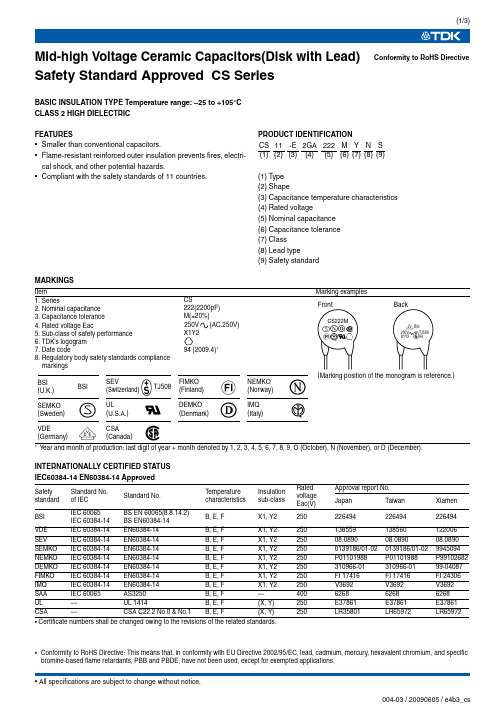
Mid-high Voltage Ceramic Capacitors(Disk with Lead)Safety Standard Approved CS SeriesBASIC INSULATION TYPE Temperature range: –25 to +105°C CLASS 2 HIGH DIELECTRICFEATURES•Smaller than conventional capacitors.•Flame-resistant reinforced outer insulation prevents fires, electri-cal shock, and other potential hazards.•Compliant with the safety standards of 11 countries.PRODUCT IDENTIFICATION(1)Type (2)Shape(3)Capacitance temperature characteristics (4)Rated voltage(5)Nominal capacitance (6)Capacitance tolerance (7)Class (8)Lead type(9) Safety standardMARKINGSear and month of production: last digit of year + month denoted by 1, 2, 3, 4, 5, 6, 7, 8, 9, O (October), N (November), or D (December).INTERNATIONALL Y CERTIFIED STATUS IEC60384-14 EN60384-14 Approved• Certificate numbers shall be changed owing to the revisions of the related standards.Conformity to RoHS DirectiveCS 11-E 2GA 222M Y N S (1)(2)(3)(4)(5)(6)(7)(8)(9)ItemMarking examplesSafety standard Standard No. of IEC Standard No.Temperature characteristics Insulation sub-class Rated voltage Eac(V)Approval report No.Japan T aiwan Xiamen BSI IEC 60065IEC 60384-14BS EN 60065(8.8.14.2)BS EN60384-14B, E, F X1, Y2250226494226494226494VDE IEC 60384-14EN60384-14B, E, F X1, Y2250138559138560122006SEV IEC 60384-14EN60384-14B, E, F X1, Y225008.089008.089008.0890SEMKO IEC 60384-14EN60384-14B, E, F X1, Y22500139186/01-020139186/01-029945094NEMKO IEC 60384-14EN60384-14B, E, F X1, Y2250P01101988P01101988P99102682DEMKO IEC 60384-14EN60384-14B, E, F X1, Y2250310966-01310966-0199-04087FIMKO IEC 60384-14EN60384-14B, E, F X1, Y2250FI 17416FI 17416FI 24306IMQ IEC 60384-14EN60384-14B, E, F X1, Y2250V3692V3692V3692SAA IEC 60065AS3250B, E, F —400626862686268UL —UL 1414B, E, F (X, Y)250E37861E37861E37861CSA—CSA C22.2 No.0 & No.1B, E, F(X, Y)250LR35801LR65972LR65972)TJ508CS222M250V X1Y2BSITJ50894•Conformity to RoHS Directive: This means that, in conformity with EU Directive 2002/95/EC, lead, cadmium, mercury, hexavalent chromium, and specific bromine-based flame retardants, PBB and PBDE, have not been used, except for exempted applications.CAPACITANCE AND DIMENSIONS∗ : Lead shape symbolSHAPES AND DIMENSIONS VERTICAL KINK LEAD TYPEDimensions in mm•We recommend using a vertical kink type.•For bulk products, we recommend a short lead type with the symbol N.Part No.Capacitance temperature characteristicsCapacitance (pF)Capacitance tolerance Dimensions (mm)T aping dimensions D max.F ød CS70-B2GA101KY S B(±10%)100K(±10%)77.5±1.50.6±0.05V2CS70-B2GA151KY S 150K(±10%)77.5±1.50.6±0.05V2CS70-B2GA221KY S 220K(±10%)77.5±1.50.6±0.05V2CS85-B2GA331KY S 330K(±10%)8.57.5±1.50.6±0.05V2CS85-B2GA471KY S 470K(±10%)8.57.5±1.50.6±0.05V2CS95-B2GA681KY S 680K(±10%)9.57.5±1.50.6±0.05V2CS10-B2GA102KY S 1,000K(±10%)107.5±1.50.6±0.05V2CS80-E2GA102MY S E(+20, –55%)1,000M(±20%)87.5±1.50.6±0.05V2CS90-E2GA152MY S 1,500M(±20%)97.5±1.50.6±0.05V2CS11-E2GA222MY S 2,200M(±20%)10.57.5±1.50.6±0.05V2CS13-E2GA332MY S 3,300M(±20%)12.57.5±1.50.6±0.05V2CS14-E2GA392MY S 3,900M(±20%)13.57.5±1.50.6±0.05V2CS15-E2GA472MY S 4,700M(±20%)14.57.5±1.50.6±0.05V3CS12-F2GA472MY S F(+30, –80%)4,700M(±20%)127.5±1.50.6±0.05V2CS17-F2GA103MY S1,0000M(±20%)16.510±20.6±0.05—Long lead Short lead T aping Vertical kinkSymbol GSymbol NSymbol VTAPING DIMEMSIONSVERTICAL KINK LEAD TYPEItemSymbol Dimensions (mm)RemarksV1V2V3Body diameter D Depends on the specification of each product.Body thickness T Depends on the specification of each product.Lead-wire diameter ød 0.6±0.050.6±0.050.6±0.05Pitch of component P 12.7±1.015.0±1.030.0±1.0Including the slant of body Feed hole pitch P 012.7±0.315.0±0.315.0±0.3Excepting the tape splicing partFeed hole center to lead P 1 3.85±0.7 3.75±0.7 3.75±0.7Feed hole center to component centerP 2 6.35±1.37.5±1.37.5±1.3Including the slanting body due to bending lead-wire Lead-to lead distance F 5+0.8, –0.27.5±0.87.5±0.8Measuring point is bottom kinkComponent alignment, F-R Δh 0±2.00±2.00±2.0Including the slanting body due to bending lead-wireT ape widthW 18.0+1.0, –0.518.0+1.0, –0.518.0+1.0, –0.5Adhesive tape width W 011.5min.11.5min.11.5min.Hole positionW 19.0±0.59.0±0.59.0±0.5Adhesive tape position W 2 3.0max. 3.0max. 3.0max.Adhesive tape do not stick out the tapeBottom of kink from tape center H 016.0+1.5, –0.516.0+1.5, –0.516.0+1.5, –0.5Height of body from tape center H 146.0max.46.0max.46.0max.Lead-wire protrusion 1.0max. 1.0max. 1.0max.Feed hole diameter D 0 4.0±0.2 4.0±0.2 4.0±0.2T otal tape tickness t 0.6±0.30.6±0.30.6±0.3Including adhesive tapeLength of snipped lead L 11.0max.11.0max.11.0max.Coating on lead C 4.0max. 4.0max. 4.0max.Height of kink A 4.0max. 4.0max. 4.0max.Measuring point is bottom kinkSpring actionS2.0max.2.0max.2.0max.•For more information about products with other capacitance or other data, please contact us.。
易用Logic PM2220电力表说明书
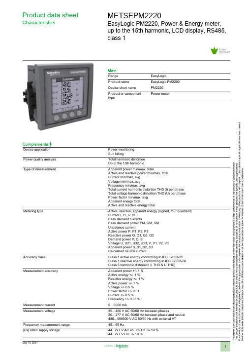
T h e i n f o r m a t i o n p r o v i d e d i n t h i s d o c u m e n t a t i o n c o n t a i n s g e n e r a l d e s c r i p t i o n s a n d /o r t e c h n i c a l c h a r a c t e r i s t i c s o f t h e p e r f o r m a n c e o f t h e p r o d u c t s c o n t a i n e d h e r e i n .T h i s d o c u m e n t a t i o n i s n o t i n t e n d e d a s a s u b s t i t u t e f o r a n d i s n o t t o b e u s e d f o r d e t e r m i n i n g s u i t a b i l i t y o r r e l i a b i l i t y o f t h e s e p r o d u c t s f o r s p e c i f i c u s e r a p p l i c a t i o n s .I t i s t h e d u t y o f a n y s u c h u s e r o r i n t e g r a t o r t o p e r f o r m t h e a p p r o p r i a t e a n d c o m p l e t e r i s k a n a l y s i s , e v a l u a t i o n a n d t e s t i n g o f t h e p r o d u c t s w i t h r e s p e c t t o t h e r e l e v a n t s p e c i f i c a p p l i c a t i o n o r u s e t h e r e o f .N e i t h e r S c h n e i d e r E l e c t r i c I n d u s t r i e s S A S n o r a n y o f i t s a f f i l i a t e s o r s u b s i d i a r i e s s h a l l b e r e s p o n s i b l e o r l i a b l e f o r m i s u s e o f t h e i n f o r m a t i o n c o n t a i n e d h e r e i n .Product data sheetCharacteristicsMETSEPM2220EasyLogic PM2220, Power & Energy meter,up to the 15th harmonic, LCD display, RS485,class 1MainRange EasyLogic Product name EasyLogic PM2200Device short name PM2220Product or component typePower meterComplementaryDevice application Power monitoring Sub billingPower quality analysis Total harmonic distortion Up to the 15th harmonicType of measurementApparent power min/max, totalActive and reactive power min/max, total Current min/max, avg Voltage min/max, avg Frequency min/max, avgTotal current harmonic distortion THD (I) per phase Total voltage harmonic distortion THD (U) per phase Power factor min/max, avg Apparent energy totalActive and reactive energy totalMetering typeActive, reactive, apparent energy (signed, four quadrant)Current I, I1, I2, I3Peak demand currentsPeak demand power PM, QM, SM Unbalance currentActive power P, P1, P2, P3Reactive power Q, Q1, Q2, Q3Demand power P, Q, SVoltage U, U21, U32, U13, V, V1, V2, V3Apparent power S, S1, S2, S3Calculated neutral currentAccuracy classClass 1 active energy conforming to IEC 62053-21Class 1 reactive energy conforming to IEC 62053-24Class 5 harmonic distorsion (I THD & U THD)Measurement accuracyApparent power +/- 1 %Active energy +/- 1 %Reactive energy +/- 1 %Active power +/- 1 %Voltage +/- 0.5 %Power factor +/- 0.01Current +/- 0.5 %Frequency +/- 0.05 %Measurement current 5…6000 mAMeasurement voltage35…480 V AC 50/60 Hz between phases20…277 V AC 50/60 Hz between phase and neutral 480…999000 V AC 50/60 Hz with external VT Frequency measurement range 45…65 Hz[Us] rated supply voltage44...277 V AC 45...65 Hz +/- 10 %44...277 V DC +/- 10 %Network frequency50 Hz60 HzRide-through time100 Ms 120 V AC typical400 Ms 230 V AC typical50 ms 125 V DC typicalLine Rated Current1 A5 AMaximum power consumption in VA6 VA 277 V ACMaximum power consumption in W 3.3 W (power lines (AC))2 W at 277 V (power lines (DC))Input impedance Current (impedance <= 0.3 mOhm)Voltage (impedance > 5 MOhm)Tamperproof of settings Protected by access codeDisplay type Backlit LCDDisplay colour MonochromeDisplay resolution128 x 128 pixelsDemand intervals Configurable from 1 to 60 minInformation displayed Demand current (past value)Demand current (present value)Demand power (past value)Demand power (present value)VoltageCurrentFrequencyEnergy consumptionHarmonic distortionPower factorActive powerApparent powerReactive powerUnbalanced in %Harmonic amplitudeControl type 4 x buttonLocal signalling Red LED: output signal 1...9999000 pulse/ k_h (kWh, kVAh, kVARh)Green LED: module operation and integrated communicationNumber of inputs0Number of outputs0Communication port protocol Modbus RTU 4800 bps, 9600 bps, 19200 bps, 38.4 Kbps even/odd or none - 2wires 2500 VCommunication port support Screw terminal block: RS485Data recording Time stampingMin/max for 8 parametersFunction available Real time clockSampling rate64 samples/cycleCybersecurity Enable/disable communication portsCommunication service Remote monitoringLanguage SpanishFrenchEnglishRussianPortugueseGermanChineseProduct certifications CE IEC 61010-1CULus UL 61010-1CULus conforming to CSA C22.2 No 61010-1RCMEACC-TickMounting mode Clip-onMounting position VerticalMounting support FrameworkProvided equipment 1 x Installation guideMeasurement category Category III 480 VCategory II 480…600 VElectrical insulation class Double insulationClass IIFlame retardance V-0 conforming to UL 94Connections - terminals Current transformer screw connection bottom) 6Voltage inputs screw connection top) 4Material PolycarbonateWidth 3.78 in (96 mm)Depth Total 3.00 in (76.09 mm)Embedded 2.43 in (61.64 mm)Height 3.78 in (96 mm)Net Weight10.58 oz (300 g)Compatibility code PM2220EnvironmentService life7 year(s)IP degree of protection IP54 front: conforming to IEC 60529Body IP30 IEC 60529Relative humidity5…95 % 122 °F (50 °C)Pollution degree2Ambient air temperature for operation14…140 °F (-10…60 °C)Ambient air temperature for storage-13…158 °F (-25…70 °C)Operating altitude<= 6561.68 ft (2000 m)Electromagnetic compatibility Electrostatic discharge conforming to IEC 61000-4-2Radiated radio-frequency electromagnetic field immunity test IEC 61000-4-3Electrical fast transient/burst immunity test conforming to IEC 61000-4-4Surge immunity test IEC 61000-4-5Conducted RF disturbances conforming to IEC 61000-4-6Magnetic field at power frequency conforming to IEC 61000-4-8Voltage dips and interruptions immunity test IEC 61000-4-11Emission tests conforming to FCC part 15 class AOvervoltage category IIIOrdering and shipping detailsGTIN03606480800177Nbr. of units in pkg.1Package weight(Lbs)9.52 oz (270 g)Packing UnitsUnit Type of Package 1PCEPackage 1 Height 3.78 in (9.6 cm)Package 1 width 2.65 in (6.72 cm)Package 1 Length 4.00 in (10.16 cm)Unit Type of Package 2BB1Number of Units in Package 21Package 2 Weight12.80 oz (363 g)Package 2 Height 4.53 in (11.5 cm)Package 2 width 3.43 in (8.7 cm)Package 2 Length 4.72 in (12 cm)Unit Type of Package 3S03Number of Units in Package 318Package 3 Weight15.48 lb(US) (7.02 kg)Package 3 Height11.81 in (30 cm)Package 3 width11.81 in (30 cm)Package 3 Length15.75 in (40 cm)Offer SustainabilitySustainable offer status Green Premium productREACh Regulation REACh DeclarationEU RoHS Directive Compliant EU RoHS DeclarationMercury free YesRoHS exemption information YesChina RoHS Regulation China RoHS Declaration Circularity Profile End Of Life Information。
KOM2125中文资料
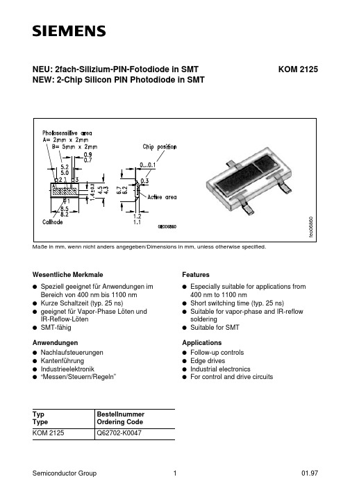
NEU: 2fach-Silizium-PIN-Fotodiode in SMT NEW: 2-Chip Silicon PIN Photodiode in SMTWesentliche Merkmaleq Speziell geeignet für Anwendungen imBereich von 400 nm bis 1100 nm q Kurze Schaltzeit (typ. 25 ns)q geeignet für Vapor-Phase Löten und IR-Reflow-Löten q SMT-fähigAnwendungenq Nachlaufsteuerungen q Kantenführung q Industrieelektronikq “Messen/Steuern/Regeln”Featuresq Especially suitable for applications from400 nm to 1100 nmq Short switching time (typ. 25 ns)q Suitable for vapor-phase and IR-reflow solderingq Suitable for SMTApplicationsq Follow-up controls q Edge drivesq Industrial electronicsq For control and drive circuitsKOM 2125Typ Type Bestellnummer Ordering Code KOM 2125Q62702-K0047Maße in mm, wenn nicht anders angegeben/Dimensions in mm, unless otherwise specified.f e o 06860Grenzwerte Maximum RatingsBezeichnung Description SymbolSymbolWertValueEinheitUnitBetriebs- und Lagertemperatur Operating and storage temperature range Top;T stg–40...+80°CSperrspannung Reverse voltage VR60VVerlustleistung,T A = 25°C Total power dissipation Ptot150mWKennwerte(T A = 25°C, Normlicht A, 2856 K) Characteristics(T A = 25°C, standard light A, 2856 K)Bezeichnung Description SymbolSymbolWertValueEinheitUnitFotoempfindlichkeit,V R = 5 V;Diode A Spectral sensitivity Diode B S40 (≥30)100 (≥75)nA/IxWellenlänge der max. FotoempfindlichkeitWavelength of max. sensitivityλS max850nmSpektraler Bereich der FotoempfindlichkeitS = 10 % von SmaxSpectral range of sensitivityS = 10 % of Smaxλ400...1100nmBestrahlungsempfindliche Fläche Diode A Radiant sensitive area Diode B A410mm2Abmessung der bestrahlungsempfindlichen FlächeDimensions of radiant sensitive area L×BL×W2×2, 2×5mm×mmAbstand Chipoberfläche zu VergußoberflächeDistance chip front to case sealH0.3mmHalbwinkel Half angle ϕ±60Graddeg.Dunkelstrom,V R = 10 V Diode A Dark current Diode B IR5 (≤30)10 (≤30)nASpektrale FotoempfindlichkeitSpectral sensitivitySλ0.62A/WQuantenausbeute Quantum yield η0.90ElectronsPhotonLeerlaufspannung,E v = 1000 Ix Open-circuit voltageV O 350 (≥300)mV Kurzschlußstrom,E v = 1000 Ix Diode A Short-circuit current Diode B I SC 3895µA Anstiegszeit/Abfallzeit Diode A Rise and fall time Diode BR L = 50Ω;V R = 5 V;λ= 850 nm;I P = 800 µAt r ,t f1825nsDurchlaßspannung,I F = 100 mA;E = 0Forward voltageV F 1.0V Kapazität Diode A CapacitanceDiode BV R = 0 V;f = 1 MHz;E = 0C 040100pFTemperaturkoeffizient von V O Temperature coefficient of V O TC V – 2.6mV/K Temperaturkoeffizient von I P Temperature coefficient of I P TC I0.18%/KRauschäquivalente StrahlungsleistungDiode A Noise equivalent power Diode B V R = 10 VNEP6.4×10– 149.1×10– 14 W √Hz Nachweisgrenze,V R = 10 V Diode A Detection limitDiode B D*3.1×10123.5×1012cm ·√Hz WKennwerte (T A = 25°C, Normlicht A, 2856 K)Characteristics (T A = 25°C, standard light A, 2856 K) (cont’d)Bezeichnung DescriptionSymbol SymbolWert Value Einheit UnitRelative spectral sensitivity S rel =f (λ)Dark current,I R =f (V R ), E = 0normalized to 10 V/25oCPhotocurrent I P =f (E v ),V R = 5 V Open-circuit voltage V O =f (E v )CapacitanceC =f (V R ), f = 1 MHz,E= 0Total power dissipation P tot =f (T A )Dark current I R =f (T A ),V R = 10 V , E = 0, normalized to T A = 25o CDirectional characteristics S rel =f (ϕ)。