KEY转换器说明书(DOC)
中文智能转换器说明书
MGG/C型电磁流量计使用说明书开封威利仪表有限公司MGG/C型电磁流量计使用说明书1 产品用途与适用范围1.1 特点:■可编程频率低频矩形波励磁,提高了流量测量的稳定性,功率损耗低;■采用16位嵌入式微处理器,运算速度快。
精度高;■全数字量处理,抗干扰能力强,测量可靠,精度高,流量测量范围度可达1500 : 1;■超低EMI开关电源,适用电源电压变化范围大。
抗EMC性能好;■全汉字菜单操作,使用方便,操作简单,易学易懂;■高清晰度背光LCD显示;■具有双向流量测量、双向总量累计功能,电流、频率具备双向输出功能。
■内部具有三个积算器可分别显示正向累计量、反向累计量及差值积算量。
■具有RS485或RS232C数字通讯信号输出;■具有电导率测量功能,可以判别传感器是否空管;■恒流励磁电流范围大,可与不同公司、不同类型的电磁流量传感器配套使用;■具有自检与自诊断功能;■采用SMD器件和表面安装(SMT)技术,电路可靠性高;■仪表内部设计有不掉电时钟,可记录16次掉电时间。
1.2主要用途MGG/C型电磁流量计用来测量封闭管道中导电流体的体积流量。
广泛地适用于石油化工、钢铁冶金、给水排水、水利灌溉、水处理、环保污水总量控制、造纸、医药、食品等工、农业部门的生产工艺过程流量测量和控制;适用于导电液体的总量计量。
1.3正常工作条件环境温度:分体型–10~+ 60℃;相对湿度:5%~90%;供电电源:单相交流电85~265V,45~63Hz;功率:与传感器配套,小于20W。
1.4 试验参比条件环境温度:20℃±2℃相对湿度:45%~85%电源电压:220±2%电源频率:50Hz±5%谐波含量小于5%。
预热时间:30min2产品型式转换器与传感器分离安装的分体型和与传感器组成一体的一体型两种结构形式。
3工作原理电磁流量计的工作原理基于法拉第电磁感应定律。
当一个导体在磁场内运动,在与磁场方向、运动方向相互垂直方向的导体两端,会有感应电动势产生。
基尔斯特 9329A … 9389A 型力矩转换器说明书
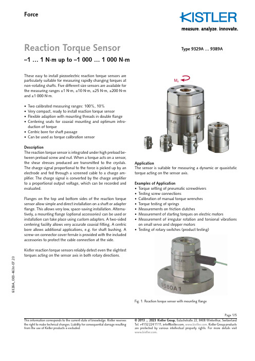
Page 1/5ForceReaction Torque Sensor–1 … 1 N·m up to –1 000 … 1 000 N·m9329A _000-463e -07.23© 2013 ... 2023 Kistler Group, Eulachstraße 22, 8408 Winterthur, Switzerland . Kistler Group products This information corresponds to the current state of knowledge. Kistler reserves the right to make technical changes. Liability for consequential damage resulting Type 9329A … 9389AThese easy to install piezoelectric reaction torque sensors are particularly suitable for measuring rapidly changing torques at non-rotating shafts. Five different size sensors are available for the measuring ranges ±1 N·m, ±10 N·m, ±25 N·m, ±200 N·m and ±1 000 N·m.• Two calibrated measuring ranges: 100%, 10%• Very compact, ready to install reaction torque sensor• Flexible adaption with mounting threads in double flange • Centering seats for coaxial mounting and optimum intro-duction of torque• Centric bore for shaft passage• Can be used as torque calibration sensorDescriptionThe reaction torque sensor is integrated under high preload be-tween preload screw and nut. When a torque acts on a s ensor, the shear stresses produced are transmitted to the c rystals. The charge signal proportional to the force is picked up by an electrode and fed through a screened cable to a charge am-plifier. The charge signal is converted by the charge amplifier to a proportional output voltage, which can be r ecorded and evaluated.Flanges on the top and bottom sides of the reaction torque sensor allow simple and direct installation on a shaft or adapter flange. This allows very low, space-saving installation. Alterna-tively, a mounting flange (optional accessories) can be used or installation can take place using custom adapters. A two-sided centering facility allows very accurate coaxial fitting. A centric bore allows additional applications, e.g. for shaft bushing. A screw-on connector cover ferrule is provided with the included accessories to protect the cable connection at the side. Kistler reaction torque sensors reliably detect even the slightesttorques acting on the sensor axis in both rotary directions.M zApplicationThe sensor is suitable for measuring a dynamic or quasistatic torque acting on the sensor axis.Examples of Application• Torque setting of pneumatic screwdrivers • Testing screw connections• Calibration of manual torque wrenches • Torque testing of springs• Measurements on friction clutches• Measurement of starting torques on electric motors• Measurement of irregular rotation and torsional vibrations on small servo and stepper motors•Testing of rotary switches (product testing)Fig. 1: Reaction torque sensor with mounting flangePage 2/59329A _000-463e -07.23© 2013 ... 2023 Kistler Group, Eulachstraße 22, 8408 Winterthur, Switzerland Tel.+41522241111,****************,. Kistler Group products This information corresponds to the current state of knowledge. Kistler reserves the right to make technical changes. Liability for consequential damage resulting Dimensions Reaction Torque Sensor Type 9329A … 9389ADimensions in mmType D D1D2D3*D4 H A B C E F G K T S x y 9329A20146419.51726313.37.427.4–36M36 2.50.20.19339A 302110828.52634416.610.240.23643.5M48 2.50.30.129349A 3626141134.53242521.710.246.23946.5M59 2.50.350.159369A 54402117534860832.510.464.44856M813 2.50.50.159389A100703023.598901301468.710.7110.770.780.5M12303––* Free access with mounted centering ringsFig. 3: Type 9329AFig. 2: Type 9339A … 9369A with connector protection Fig. 4: Type 9389A with connector protectionConnecting cableConnecting cableConnector protectionPage 3/59329A _000-463e -07.23© 2013 ... 2023 Kistler Group, Eulachstraße 22, 8408 Winterthur, Switzerland Tel.+41522241111,****************,. Kistler Group products This information corresponds to the current state of knowledge. Kistler reserves the right to make technical changes. Liability for consequential damage resulting Technical dataReaction Torque Sensor Type9329A 9339A 9349A 9369A 9389AMeasuring range M z N·m –1 … 1 –10 … 10 –25 … 25 –200 … 200 –1 000 … 1 000Overload M z N·m –1.2/1.2 –12/12 –30/30 –240/240 –1 200 … 1 200Calibrated measuring ranges M z N·m –1 … 1 –10 … 10 –25 … 25 –100 … 100 –1 000 … 1 000M z N·m –0.1 … 0.1 –1 … 1 –2.5 … 2.5 –20 … 20 –100 … 100Threshold M z mN·m <0.03 <0.18 <0.35 <0.62 <0.78Sensitivity pC/N·m ≈–2 170 ≈–460 ≈–230 ≈–130 ≈–100Linearity, all measuring ranges %FSO ≤±0.2 ≤±0.2 ≤±0.2 ≤±0.2 ≤±0.2Hysteresis, all measuring ranges %FSO ≤0.3 ≤0.3 ≤0.3 ≤0.3 ≤0.3Tensile/compression force, max.F z kN –3/9 –5/14 –10/8 –10/10 –60/60Crosstalk F z → M zmN·m/N ≤±0.01 ≤±0.05 ≤±0.01 ≤±0.02 ≤±0.01Side force, max. 1)F x,y kN 0.47 0.38 0.44 0.27 3.66 (M z = 100%; F z = 0)Crosstalk (typical) F x,y → M z mN·m/N <0.5 <0.3 <0.3 <0.3 <0.2Bending moment, max. M x,y N·m 17.3 20 30 27 698 (M z = 100%; F z = 0) Crosstalk M x,y → M z mN·m/N·m <8<8<8<12<10Rigidity c ϕ (M z )mN·m/μrad ≈17 ≈96 ≈189 ≈924 ≈1 540Natural frequency (torsion) f n kHz >53 >36 >33 >23 >11Operating temperature range °C –20 … 80 –40 … 120 –40 … 120 –40 … 120 –40 … 120Temperature coefficient %/°C 0.02 – 0.02 – 0.02 – 0.02 – 0.02 of sensitivityInsulation resistance at 20 °CΩ >1013 >1013 >1013 >1013 >1013Capacitance pF ≈73 ≈43 ≈340 ≈350 ≈910Connection KIAG 10-32 neg.Connector protectorno yes yes yes yes Degree of protection (with cable connected) EN60529 IP65 Case material DIN 1.4542 Weightg 50 137 243 800 6 7201)Application of force in plane of flangeGeneralThe torque should be introduced by the smallest possiblee ccentricity of the axes to be connected (<0.02 mm). Bending moment and shear forces should be avoided as far as p ossible.The surfaces contacting the reaction torque sensor must be flat, rigid and clean. The centering facility on both sides of the reaction torque sensor using centering rings (included acces-sories) allow very accurate coaxial fitting.The sensor can be fitted directly via the integral flanges on two sides. Special adapters can be manufactured for adaptation to the customer's specific applications.Page 4/59329A _000-463e -07.23© 2013 ... 2023 Kistler Group, Eulachstraße 22, 8408 Winterthur, Switzerland Tel.+41522241111,****************,. Kistler Group products This information corresponds to the current state of knowledge. Kistler reserves the right to make technical changes. Liability for consequential damage resulting Adaption A: Installation in Shaft with Adapter for Shaft Journal with PinCustomized tool adapterAdapter for toolshank with pin Pinned during installationPinned during installation Adaption B: Installation in Shaft with Adapter FlangeAdapter flange for flat mounting in shaftCustomizedcentering ring (g6)Customizedcentering ring (g6)Adaption C: Installation with Shaft with Integrated FlangeCentering pin g6 on customized shaftAdapter for cylinder bore recess with pin Adaption D: Adapter Flange for Wrenches with External Square HeadOverview of Installation VariantsM zCentering rings(incl. accessories)Mounting flange Type 9580A…(optional accessories)M zM zPage 5/59329A _000-463e -07.23© 2013 ... 2023 Kistler Group, Eulachstraße 22, 8408 Winterthur, Switzerland Tel.+41522241111,****************,. Kistler Group products This information corresponds to the current state of knowledge. Kistler reserves the right to make technical changes. Liability for consequential damage resulting Adaption E: Screw Plate with Spring AssemblySpring assemblyCustomizedscrew plate Adaption F: Desktop Installation with Mounting FlangeOrderinkey T ype Scope of delivery including accessories Reaction Torque Sensor 9329A • 2 x Centering ring 3.420.196Reaction Torque Sensor 9339A • Connector protection 3.414.366• 2 x Centering ring 3.420.179Reaction Torque Sensor 9349A • Connector protection 3.414.366• 2 x Centering ring 3.420.180Reaction Torque Sensor 9369A • Connector protection 3.414.366• 2 x Centering ring 3.420.181Reaction Torque Sensor 9389A • Connector protection 3.414.366• 2 x Centering ring3.420.197Optional accessories Type• Connecting cable(see data sheet 1631C_000-346)• Mounting flange9580A…for ype ype D1 d d1 d2 d3 d4 d5 d6 H2 T 1 N 9329A 9580A9 14 40 30 6 4.5 3.2 4.5 5.6 8 2 39339A 9580A0 21 62 50 10 5.5 4.3 8.5 7.5 11 2 59349A 9580A1 26 70 55 14 6.6 5.3 12 9 13 2 69369A 9580A2 40 100 78 21 13.5 8.4 18 14 22 2 99389A 9580A4 70 180 135 30 17 13 25 20 30 2.5 13Mounting flangeCentering rings (incl. accessories)Centering rings (incl. accessories)Mounting flange (optional accessories)M zFig. 5: Type 9580A9 ... A2Fig. 6: Type 9580A4。
IntuiKey 系列键盘说明书

IntuiKey 系列数字键盘目录1说明﹍﹍﹍﹍﹍﹍﹍﹍﹍﹍﹍﹍﹍﹍﹍﹍﹍﹍﹍﹍﹍﹍﹍﹍﹍﹍﹍﹍﹍4 1.1手册使用指南﹍﹍﹍﹍﹍﹍﹍﹍﹍﹍﹍﹍﹍﹍﹍﹍﹍﹍﹍﹍﹍﹍﹍﹍﹍4 1.2开包﹍﹍﹍﹍﹍﹍﹍﹍﹍﹍﹍﹍﹍﹍﹍﹍﹍﹍﹍﹍﹍﹍﹍﹍﹍﹍﹍﹍﹍4 1.3服务﹍﹍﹍﹍﹍﹍﹍﹍﹍﹍﹍﹍﹍﹍﹍﹍﹍﹍﹍﹍﹍﹍﹍﹍﹍﹍﹍﹍﹍4 1.4了解Intuikey﹍﹍﹍﹍﹍﹍﹍﹍﹍﹍﹍﹍﹍﹍﹍﹍﹍﹍﹍﹍﹍﹍﹍﹍﹍4 2安装﹍﹍﹍﹍﹍﹍﹍﹍﹍﹍﹍﹍﹍﹍﹍﹍﹍﹍﹍﹍﹍﹍﹍﹍﹍﹍﹍﹍﹍4 2.1确定Intuikey系统配置﹍﹍﹍﹍﹍﹍﹍﹍﹍﹍﹍﹍﹍﹍﹍﹍﹍﹍﹍﹍﹍﹍2.2安装﹍﹍﹍﹍﹍﹍﹍﹍﹍﹍﹍﹍﹍﹍﹍﹍﹍﹍﹍﹍﹍﹍﹍﹍﹍﹍﹍﹍﹍﹍2.3连接﹍﹍﹍﹍﹍﹍﹍﹍﹍﹍﹍﹍﹍﹍﹍﹍﹍﹍﹍﹍﹍﹍﹍﹍﹍﹍﹍﹍﹍﹍3操作﹍﹍﹍﹍﹍﹍﹍﹍﹍﹍﹍﹍﹍﹍﹍﹍﹍﹍﹍﹍﹍﹍﹍﹍﹍﹍﹍﹍﹍﹍3.1学习Intuikey组成部分﹍﹍﹍﹍﹍﹍﹍﹍﹍﹍﹍﹍﹍﹍﹍﹍﹍﹍﹍﹍﹍﹍3.1.1状态显示﹍﹍﹍﹍﹍﹍﹍﹍﹍﹍﹍﹍﹍﹍﹍﹍﹍﹍﹍﹍﹍﹍﹍﹍﹍﹍﹍3.1.2按键区﹍﹍﹍﹍﹍﹍﹍﹍﹍﹍﹍﹍﹍﹍﹍﹍﹍﹍﹍﹍﹍﹍﹍﹍﹍﹍﹍﹍3.1.3软按键和软按键显示﹍﹍﹍﹍﹍﹍﹍﹍﹍﹍﹍﹍﹍﹍﹍﹍﹍﹍﹍﹍﹍﹍3.1.4操纵杆﹍﹍﹍﹍﹍﹍﹍﹍﹍﹍﹍﹍﹍﹍﹍﹍﹍﹍﹍﹍﹍﹍﹍﹍﹍﹍﹍﹍3.2使用Intuikey键盘操纵系统﹍﹍﹍﹍﹍﹍﹍﹍﹍﹍﹍﹍﹍﹍﹍﹍﹍﹍﹍﹍3.2.1操纵Intuikey菜单的一般指导方针﹍﹍﹍﹍﹍﹍﹍﹍﹍﹍﹍﹍﹍﹍﹍﹍﹍3.2.2选择要控制的设备﹍﹍﹍﹍﹍﹍﹍﹍﹍﹍﹍﹍﹍﹍﹍﹍﹍﹍﹍﹍﹍﹍﹍3.2.3使用按键区进行数字输入(摄像机控制)﹍﹍﹍﹍﹍﹍﹍﹍﹍﹍﹍﹍﹍﹍﹍3.3报警/警报/动作指定﹍﹍﹍﹍﹍﹍﹍﹍﹍﹍﹍﹍﹍﹍﹍﹍﹍﹍﹍﹍﹍﹍﹍3.4配置Intuikey键盘﹍﹍﹍﹍﹍﹍﹍﹍﹍﹍﹍﹍﹍﹍﹍﹍﹍﹍﹍﹍﹍﹍﹍﹍3.4.1访问键盘控制模式﹍﹍﹍﹍﹍﹍﹍﹍﹍﹍﹍﹍﹍﹍﹍﹍﹍﹍﹍﹍﹍﹍﹍3.4.2键盘控制菜单选项﹍﹍﹍﹍﹍﹍﹍﹍﹍﹍﹍﹍﹍﹍﹍﹍﹍﹍﹍﹍﹍﹍﹍4控制Allegiant系列视频转换器﹍﹍﹍﹍﹍﹍﹍﹍﹍﹍﹍﹍﹍﹍﹍﹍﹍﹍﹍4.1Allegiant主控菜单﹍﹍﹍﹍﹍﹍﹍﹍﹍﹍﹍﹍﹍﹍﹍﹍﹍﹍﹍﹍﹍﹍﹍﹍4.1.1访问Allegiant主控菜单﹍﹍﹍﹍﹍﹍﹍﹍﹍﹍﹍﹍﹍﹍﹍﹍﹍﹍﹍﹍﹍4.2编制/控制Allegiant功能﹍﹍﹍﹍﹍﹍﹍﹍﹍﹍﹍﹍﹍﹍﹍﹍﹍﹍﹍﹍﹍4.2.1Allegiant主控菜单命令描述﹍﹍﹍﹍﹍﹍﹍﹍﹍﹍﹍﹍﹍﹍﹍﹍﹍﹍﹍4.3Allegiant错误信息﹍﹍﹍﹍﹍﹍﹍﹍﹍﹍﹍﹍﹍﹍﹍﹍﹍﹍﹍﹍﹍﹍﹍﹍5控制SYSTEM4视频多路器﹍﹍﹍﹍﹍﹍﹍﹍﹍﹍﹍﹍﹍﹍﹍﹍﹍﹍﹍﹍5.1Mux(多路器)主控菜单﹍﹍﹍﹍﹍﹍﹍﹍﹍﹍﹍﹍﹍﹍﹍﹍﹍﹍﹍﹍﹍﹍5.1.1访问Mux主控菜单5.2编制控制Mux功能5.2.1使用Intuikey键盘控制Mux功能5.2.2Mux主控菜单命令描述5.3Mux错误信息﹍﹍﹍﹍﹍﹍﹍﹍﹍﹍﹍﹍﹍﹍﹍﹍﹍﹍﹍﹍﹍﹍﹍﹍﹍﹍6故障处理﹍﹍﹍﹍﹍﹍﹍﹍﹍﹍﹍﹍﹍﹍﹍﹍﹍﹍﹍﹍﹍﹍﹍﹍﹍﹍﹍﹍6.1系统﹍﹍﹍﹍﹍﹍﹍﹍﹍﹍﹍﹍﹍﹍﹍﹍﹍﹍﹍﹍﹍﹍﹍﹍﹍﹍﹍﹍﹍﹍6.2键盘﹍﹍﹍﹍﹍﹍﹍﹍﹍﹍﹍﹍﹍﹍﹍﹍﹍﹍﹍﹍﹍﹍﹍﹍﹍﹍﹍﹍﹍﹍6.3摄像机控制﹍﹍﹍﹍﹍﹍﹍﹍﹍﹍﹍﹍﹍﹍﹍﹍﹍﹍﹍﹍﹍﹍﹍﹍﹍﹍﹍6.4混合﹍﹍﹍﹍﹍﹍﹍﹍﹍﹍﹍﹍﹍﹍﹍﹍﹍﹍﹍﹍﹍﹍﹍﹍﹍﹍﹍﹍﹍﹍附录A: Intuikey菜单参考﹍﹍﹍﹍﹍﹍﹍﹍﹍﹍﹍﹍﹍﹍﹍﹍﹍﹍﹍﹍﹍﹍﹍附录B: 摄像机控制命令参考﹍﹍﹍﹍﹍﹍﹍﹍﹍﹍﹍﹍﹍﹍﹍﹍﹍﹍﹍﹍﹍附录C: 密码﹍﹍﹍﹍﹍﹍﹍﹍﹍﹍﹍﹍﹍﹍﹍﹍﹍﹍﹍﹍﹍﹍﹍﹍﹍﹍﹍﹍1介绍1.1用户手册指南该手册包含安全安装和操作IntuiKey数字键盘所需的全部信息。
日本 KETT 膜厚计 说明书
日本KETT膜厚计说明书LZ-200J内容一、概述‧‧‧‧‧‧‧1二、规格‧‧‧‧‧‧‧2三、零件名称‧‧‧‧‧‧‧3四、键盘按键解说‧‧‧‧‧‧‧4五、如何使用LZ-200C ‧‧‧‧‧‧‧6(1)仪器准备‧‧‧‧‧‧‧6(2)校正‧‧‧‧‧‧‧7(3)校正程序‧‧‧‧‧‧‧8(4)如何校正‧‧‧‧‧‧‧8(5)执行测试‧‧‧‧‧‧‧10(6)一般测量的例子‧‧‧‧‧‧‧11 六﹑如何使用功能模式‧‧‧‧‧‧‧12 七﹑操作注意事项‧‧‧‧‧‧‧16一、概述LZ200J同时运用电磁感应及涡电流原理,为了最佳使用效率并具有一内装的打印机。
特性1.校验LZ200J为一自动校验的仪器,是利用一内部的微电脑,借着已知厚度的标准片使用者亦可以自己校验仪器,微电脑以记忆方式储存校正常数,只要测试材料维持不变,即使机器关掉亦不需要再校正就可以重新开机测量,即使拿掉电池,校正记忆亦不会消失。
2.不同的统计计算可打印出来,只要一按钮,LZ200J即可印出标准偏差,平均值,最大读数及最小读数。
3.限制功能可接受最大及最小膜厚厚度的设定(上限、下限)要测量的涂装厚度如超过范围警铃会响。
用途可测量的涂装层:(电磁性) (涡电流)在钢及铁上的非磁性膜, 油漆,塑料,漆,树脂,橡胶,氧化如油漆,塑料,漆,树脂,橡胶, 涂厚及正阳极的涂装。
氧化膜,锌,铬,锡釉,铝等。
底材(或没有上料的的本底材):(电磁性) (涡电流)钢及铁。
铝,铜,黄铜及不锈钢。
二、规格测量方法:电磁感应法涡电流测头型式: LEP20 LHP20应用:含铁金属底材上之非(非铁金属底材上之非导磁性膜厚测定) 导电膜厚测定) 测量范围:0-1500um 0-800um(32.00mils) 测量精度:15um 以下±0.3um 50um 以下±1um 15um 以上±2% 50um 以上±3% 程序校正记忆: 4组4组解析力: 0.1um(少于100um) 1um1um(高于100um)最小测试区域: 3x3 mm 5x5mm显示: 16位数点矩LCD,测量次数及组数统计功能: 测量数目及组数、平均值、标准偏差、最大值及最小值测试记忆容量:1500笔1批99组打印机: 感热式,24个字纸张宽度58mm电源: AC110V (50/60HZ) 或电池(测试机本体6个UM3 电池,打印机4个UM3电池) 周围温度: 0℃到+40℃重量: 1.1公斤尺寸:测试主机250(L) x 120(w) x 55(H)mm测头直径11mm x 90mm配件:标准校正箔片1组铁底材1片AC接头1个印表纸2卷携带盒1个操作手册1本三、零件名称:四、键盘按键解说:重置键如果让测试机打开超过10分钟,测试机会自动进入”睡眠”状态,显示器也会显示”睡眠”,按重置键就可进入测量状态校正键输入键按此键以便输入Date , Lot , Cal , Del 及Limit然后再按BR , FR, BINC ,及AC装纸键用于装纸打印机开/关键按此键时, LCD 会将“ * “ 改成“ # “清除键可清除误输入的数据功能键用于输入日期,组数,统计资料等先按此键,再按以下的键:日期键用于输入(或打印)日期组键用于输入(打印)组数删除键用于清除误输入的数据五、如何使用LZ200J(1)仪器准备此机型可同时以电池及使用AC 转换器的主供给来运作1.以内装电池来操作:将电源开关关掉并装上新的电池:用于测试机: 6个 1.5V “AA”用于打印机: 4个 1.5V “AA”请用寿命长,含碱的电池2.用主供给来运作:电源关掉,将AC转换器连接到右面的插座上,并插上电源3.用主供给及电池来操作:装上电池,连接AC转换器,LZ200J会自动转换成以AC线操作(2)将探头连接到探头插作上:1.将探头尾端插头插入主机右边的插座中,转动插头直到键导路适当地接合,最简单的方法是转动电线尾端的黑色模子部份,而不是银色的金属带2.要移去探头只要将接合器外面的金属套管从主机拉开,请不要拉电线3.打开开关4.装上印表纸割去纸的边缘,然后放入纸盒内,按”PAPER FEED”键直到纸跑出来如要印结果,日期等,轻按”PRINTER ON/OFF”键,LCD 指示”#” 记号表示打印机正在运作5.校正因为LZ200J是一相关测量的仪器,在使用前一定要用一无修饰过的底材及已知的样本来校正,一但校正了,校正常数就会贮藏在仪器中微电脑记忆库里,关掉机器并不导致校正记忆的流失,注意:A.校正一定要用与实际生产样品同样种类,形式及厚度B.在使用无修饰铁材时,须确定它没有电镀或上漆C.虽然有许多的校正方法,但用零点(就是无修饰底材)及三点校正会得到最佳的测量结果范围归零点三点校正6.探头的使用探头的设计为它永远以顶端对样本表面施加同样的压力,把探头放在要测试的部位上,与表面垂直,压下探头外面的金属套管如图6, 套管的往下动作使测试完成,对一连续的测量来讲,首先将探头移开测量表面至少10mm,再垂直地放在要测试表面上,并压下外面的套管(3)校正步骤:1.从1到4选择一使用数字<例子> 选择使用数子4keystep stroke display12342.如何校正:key stroke orstep procedure display explanation56 将探头升到空中按ENT键789 将40um箔纸放在无修饰底材上,得5个读数,按ENT 键会将读数归于40.01011 输入校正箔片的厚度值1213 将100um箔纸放在无修饰底材上,并取5个读数,依据样本的种类,除了100的数字会显现按ENT键读数归于100.01415 输入校正箔片的厚度值1617 将400um箔纸放在无修饰底材上,并取5个读数,依据样本的种类,除了400的数字会显现按ENT键读数归于400.01819 输入校正箔片的厚度值20Caution:1.在校正状态下,LCD会显示平均结果2.若输入错误校正箔片的厚度值,按”C”键后并输入正确数值,按”ENT”键后,就不能再做改正,按”CAL”键并从头开始3.当操作错误时,再按”CAL”键,并从头开始测试4.不要用相同厚度的箔片做校正,若此情形发生时,LCD会显示,按”CAL”键,并从头开始测试5.做测试<1>装探头<2>打开开关<3>校正<4>如有必要,删除<5>如有必要,打开<6>选一使用数字所有数据列表机在打印机关闭时,选记号轮流显示印4个使用数字定使用数字后,机器表机打开可用,在相同可进入测量状态的底材上用每一数字<7>输入其它数据如日期,限制(最大或最小)及组数<8>测试快速地将探头垂直地压在要测试部位的表面上是最重要的,在每次连续测量前,先将探头从测量表面至少移开10mm,然后再垂直地压在表面上6.一般测试的例子:key stroke or display printing procedure六、如何使用功能模式:DATE 此键是为了打印日期(可用8个位数)key display key display LOT 此键可打印你的数据的参考号码DEL “Delete”此键是可用来消除不需要或不正确的测试(1)(2)在此情况下(如 N=10) 刚做在此情况下,N=8的数据会被的测试及数目(N=10)就会消消除掉,但测试次数保持不变除掉,下次的测试就从(N=10)开始B.R. “Block Result”下面的数值会持续地印出(1)测试的次数(2)平均值(3)最大厚度(4)最小厚度平均值(A V) 及标准偏差(S) 是根据以下公式得来:Where N= number of measurementX= measured thicknessB.R. (Example)Key LCD Display在有” * ”符号的步骤中可按“ ENT “ 键,在一块中刚测试的块,结果就会印出,测试机可进行下一次的测试最后结果不需要时, “A.C “ 键可将仪器重置于准备下一块的测量LIMIT “Limitt”此键用于预先设定测量厚度的上下限,以警告声音来通知F.R. “最后结果”所有最后的统计结果会打印出CONT “持续测量”按”CONT”会消除”维持”循环以便连续测试,此状态下统计的计算及打印也消除要让仪器重回正常运作(维持状态)再按“ FUN “ 及“HOLD”B.INC “块数增加”当块数不敷使用时,按“FUN” 及“B.INC” 按下你需要的块数A.C “全部清除”按” A.C. “ 清除所有步骤并重置仪器um/mils 测量单位可选择um或mils,若要um单位,按” FUN ” , “um/mils”及“ENT” ,若改用成mils 按“FUN” “um/mils” 及“C” , “C”键选择um单位NO.. “使用数字”“NO”键可选择需要的使用数目(从1到4), 并可用于它的记忆确认或数字改变若要已彻消的数目不变,按“ENT” 或“C” 键七、操作注意事项1. 纸、薄膜等的厚度LE200J可用下列步骤测试非磁性片材料的厚度,比如纸、薄膜(胶卷) 、橡胶及塑料A.准备一片已擦亮的铁底材B.使用校正箔片在铁底材上校正仪器C.放一片要测试的材料在铁底材上,并将探头放在上面2.维护:A.探头需十分小心使用探头,兹建议用软布抹上石油精或酒精清洁芯片,以便下次使用B.校正标准片对仪器之校正及准确性检查来讲,校正箔片是非常重要的配件,须小心使用,当箔片北被折起来或受到损害时,尽快地更换新的,我们的KETT校正标准片在工厂内皆严格地制造和检验C.为了长期的最有效使用,兹建议一年检查一次你仪器的准确性(准确性检查可用不同厚度的校正标准片D.更换电池当下面的警告符号亮时,须关上机器换上所有的新电池a.“ % “ 测试主机及打印机的电池都没了b.“ * “ 测试主机的电池没了c.“ # “ 测试主机或打印机的电池都没了注意:a.换电池时,须开机b.即使电池完全没电了,或在测试过程中换电池,校正记忆并不消除因为它被贮存在特殊的不挥发性内存中c. 当测试机开着超过10分钟而不使用时, LCD会显示SLEEP 以节省电池,按“RESET” 键就可使用(我们建议重复测试10 到20次)文件名: 日本KETT膜厚计说明书LZ-200J目录: D:\昱跃\操作\仪器操作说明书\KETT模板: C:\Documents and Settings\lenovo\Application Data\Microsoft\Templates\Normal.dot标题: 日本KETT膜厚計說明書主题:作者: 黃小姐关键词:备注:创建日期: 2003-5-30 9:40:00修订号: 53上次保存日期: 2003-6-5 10:36:00上次保存者: User编辑时间总计: 1,070 分钟上次打印时间: 2009-4-10 17:40:00打印最终结果页数: 16字数: 999 (约)字符数: 5,697 (约)。
PAF700F Series 全 brick DC-DC 转换器说明书
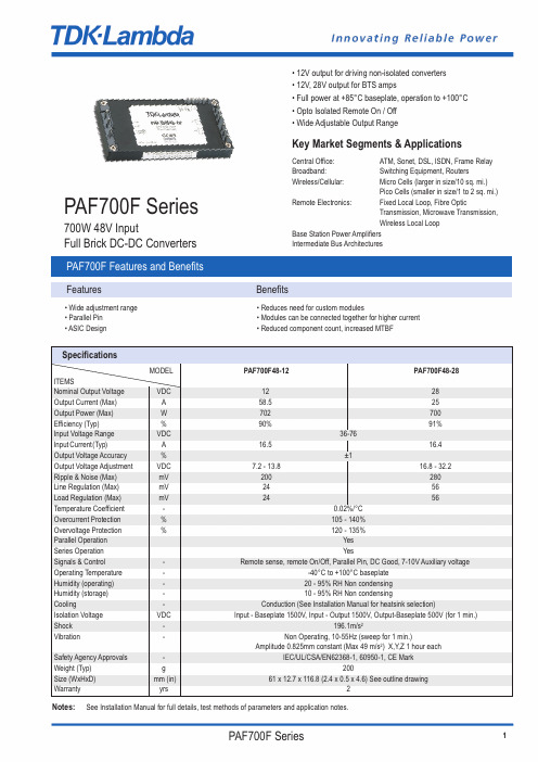
PAF700F Series700W 48V InputFull Brick DC-DC ConvertersKey Market Segments & ApplicationsCentral Office:ATM, Sonet, DSL, ISDN, Frame Relay Broadband:Switching Equipment, RoutersWireless/Cellular:Micro Cells (larger in size/10 sq. mi.)Pico Cells (smaller in size/1 to 2 sq. mi.)Remote Electronics:Fixed Local Loop, Fibre OpticTransmission, Microwave Transmission,Wireless Local LoopBase Station Power Amplifiers Intermediate Bus Architectures • 12V output for driving non-isolated converters • 12V, 28V output for BTS amps• Full power at +85°C baseplate, operation to +100°C • Opto Isolated Remote On / Off • Wide Adjustable Output RangePAF700F Features and BenefitsFeaturesBenefits• Wide adjustment range • Reduces need for custom modules• Parallel Pin • Modules can be connected together for higher current • ASIC Design• Reduced component count, increased MTBFSpecificationsNotes: See Installation Manual for full details, test methods of parameters and application notes.MODEL PAF700F48-12PAF700F48-28ITEMSNominal Output Voltage VDC 1228Output Current (Max)A 58.525Output Power (Max)W 702700Efficiency (Typ)%90% 91%Input Voltage Range VDC 36-76Input Current(Typ)A 16.516.4Output Voltage Accuracy %±1Output Voltage Adjustment VDC 7.2 - 13.816.8 - 32.2Ripple & Noise (Max)mV 200280Line Regulation (Max)mV 2456Load Regulation (Max)mV 2456Temperature Coefficient -0.02%/°C Overcurrent Protection %105 - 140%Overvoltage Protection %120 - 135%Parallel Operation Yes Series Operation YesSignals & Control-Remote sense, remote On/Off, Parallel Pin, DC Good, 7-10V Auxiliary voltageOperating Temperature --40°C to +100°C baseplate Humidity (operating)-20 - 95% RH Non condensing Humidity (storage)-10 - 95% RH Non condensingCooling-Conduction (See Installation Manual for heatsink selection)Isolation Voltage VDC Input - Baseplate 1500V, Input - Output 1500V, Output-Baseplate 500V (for 1 min.)Shock -196.1m/s 2Vibration-Non Operating, 10-55Hz (sweep for 1 min.)Amplitude 0.825mm constant (Max 49 m/s 2) X,Y,Z 1 hour eachSafety Agency Approvals -IEC/UL/CSA/EN62368-1, 60950-1, CE MarkWeight (Typ)g 200Size (WxHxD)mm (in) 61 x 12.7 x 116.8 (2.4 x 0.5 x 4.6) See outline drawingWarrantyyrs2Note1Use external fuse of fast blow type, for each unit2Put input capacitor, C1 and C2, greater than 220uf for each. If the impedance of input line is high, C1 and C2 capacitance must be greater than above.3Put output capacitor, C3 (12v: more than 470uF,28V: greater than 220uF). If the ambient temperature is less than -20C, use 4 pieces of therecommended capacitor above.4Refer to instruction manual for further details.Full Brick Max Power Full Nominal Input Output Option SuffixWatts Function VoltageVoltage PAF700F4812 or 28Blank = M3 Tapped insertsT = 3.3mm Non-threaded through holeConnection ExampleDerating CurvePart Number SchemeOutline Drawing PAF700FNoteA:Model name, input voltage range, nominal output voltage, maximum output current,country of manufacture are shown here in accordance with the specificationsB:M3 tapped holes for customer chassis mounting (FG)C:Input and output pin: 8-02D:Signal pin : 8-01E:Unless otherwise specified dimensional tolerance +0.3mmPinoutPin Description Function-Vin Negative Input Terminal+Vin Positive Input Terminal- ON/OFF Remote On/Off Negative Terminal+ON/OFF Remote On/Off Positive Terminal+V Positive Output Terminal-V Negative Output TerminalAUX7-10V Aux VoltageIOG DC GoodPC Parallel Control ConnectionTRIM Output Adjustment Trim Pin+S Positive Remote Sense-S Negative Remote SensePAF700F Oct20 v3TDK-Lambda France SAS3 Avenue du CanadaParc TechnopolisBâtiment Sigma91940 les UlisFranceTel:+33 1 60 12 71 65Fax:+33 1 60 12 71 66********************.com/frItaly Sales OfficeVia Giacomo Matteotti 6220092 Cinisello Balsamo (MI)ItalyTel:+39 02 61 29 38 63Fax:+39 02 61 29 09 00*************************.com/itNetherlands******************.com/nlTDK-Lambda Germany GmbHKarl-Bold-Strasse 4077855 AchernGermanyTel:+49 7841 666 0Fax:+49 7841 5000**************************.com/deAustria Sales OfficeAredstrasse 222544 LeobersdorfAustriaTel:+43 2256 655 84Fax:+43 2256 645 12******************.com/atSwitzerland Sales OfficeEichtalstrasse 558634 HombrechtikonSwitzerlandTel:+41 44 850 53 53Fax:+41 44 850 53 50******************.com/chNordic Sales OfficeHaderslevvej 36BDK-6000 KoldingDenmarkTel:+45 8853 8086******************.com/dkTDK-Lambda UK Ltd.Kingsley AvenueIlfracombeDevon EX34 8ESUnited KingdomTel:+44 (0) 12 71 85 66 66Fax:+44 (0) 12 71 86 48 94******************.com/ukTDK-Lambda Ltd.1 Alexander YanaiSegulaPetah-TikvaIsraelTel:+9 723 902 4333Fax:+9 723 902 4777******************.il/ilC.I.S.Commercial Support:Tel:+7 (495) 665 2627Technical Support:Tel:+7 (812) 658 0463******************/ruLocal Distribution。
电子切换器组件和配件说明书
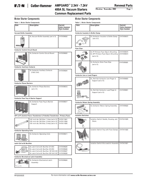
For more information visit: AMPGARD 2.3kV - 7.2kV 400A SL Vacuum StartersCommon Replacement PartsRenewal PartsPage 1Effective: November 2002RP02003002E SL Vacuum Bottle Assembly (set of 3)SL Contactor Control Circuit BoardSL Contactor Auxiliary Contacts 2 NO/ 2 NC0.81-inch dia. 5kV Max, 1 Amp (set of 3)0.81-inch dia. 5kV Max, 3 Amp (set of 3)0.81-inch dia. 5kV Max, 5 Amp (set of 3)SL Contactor Return Spring AssemblySL, Roll-Out Contactor Line Finger & Support (set of 3)SL, Roll-Out Contactor Load Finger & Support (set of 3)Isolation Switch Tray with Fuse Clamps 2147A58G022147A58G032147A58G042147A58G122147A11G612147A11G492147A11G552147A58G152147A58G182147A58G162147A58G172147A58G202147A58G222147A58G502147A58G512147A41G222147A01G01SL Latch Coil with Rectifier 24 VDC SL Latch Coil with Rectifier 48 VDC SL Latch Coil with Rectifier 125 VAC-DC SL Latch Coil with Rectifier 250 VAC-DC2147A58G252147A58G262147A58G272147A58G28SL Contactor Operating Coils2147A58G11Contactor Operating CoilsSL Contactor Mechanical Latch Assembly2147A58G24Motor Starter ComponentsTable 1. Motor Starter ComponentsItem DescriptionCurrentCutler-Hammer Style NumberMotor Starter ComponentsTable 1. Motor Starter ComponentsItem DescriptionCurrentCutler-Hammer Style NumberVacuum Bottle AssemblyContactor Control Circuit BoardContactor Auxiliary ContactsContactor Phase BarriersCPT & PT (Control Power Transformer & Potential Transformer) Primary FusesContactor Insulator & Bottle ClampFuse ClipsContactor Fuse Tray & Barrier SupportContactor Return Spring AssemblyContactor Line or Load FingersIsolation SwitchesSL Contactor Phase Barriers (set of 4)SL Contactor Insulator & Bottle Clamp (set of 3)SL PT Primary Fuse Clips & Mounting SL CPT Primary Fuse Clips & Mounting (set of 2)SL Contactor Fuse Tray & Barrier SupportSL Contactor Main Fuse Clips (set of 3)Isolation Switch Microswitch Assembly Latch Coil with RectifierContactor Mechanical Latch AssemblyIsolation Switch Handle, Housing, and Clevis2147A41G08Renewal PartsPage 2Effective: November 2002AMPGARD 2.3kV - 7.2kV 800A SJ Vacuum Starters Common Replacement PartsEaton CorporationCutler-Hammer business unit 1000 Cherrington ParkwayMoon Township, PA 15108-4312USAtel: 1-800-525-2000© 2002 Eaton Corporation All Rights Reserved Printed in USAForm No. RP02003002E November 2002Contactor CoilMagnet AssemblyBarrier AssembliesVacuum Bottle with Shunt, Support, & FingersIsolation SwitchesMiscellaneous Parts KitFuse PullerContactor Tune-up KitInterlocksL-63 Interlock (coil circuit)578D461G03L-64 Auxiliary Interlocks 1 NO 1 NC L-64 Auxiliary Interlocks 2 NO L-64 Auxiliary Interlocks 2 NC843D943G21843D943G22843D943G23Load or Line FingersMotor Starter ComponentsTable 1. Motor Starter Components800A Contactor Coils 120 VAC (set of 2)800A Contactor Coils 240 VAC (set of 2)800A Contactor Magnet Assembly with Coil 120 VAC800A Contactor Magnet Assembly with Coil 240 VAC800A Contactor Magnet Assembly without Coil800A Contactor Barrier Assembly800A Contactor Fuse Support & Barrier Assembly800A Contactor Fuse Load Fingers (between contactor & fuse) (set of 3)800A Contactor Line Fingers with Copper Support800A Contactor Line or Load Fingers without Copper Support2147A89G022147A89G012147A71G152147A89G062147A89G072147A88G022147A88G032147A88G042147A88G112147A88G12800A Contactor Miscellaneous Parts Kit 2147A88G15800A Contactor Fuse Puller2147A93G07800A Isolation Switch Handle, Housing, & Clevis2147A71G08800A Isolation Switch Tray Assembly with Line Fingers2147A81G22800A Contactor Tune-up Kit2147A99G042147A01G01Isolation Switch Microswitch Assembly Note: For additional information, call 1-800-523-3775.Motor Starter ComponentsTable 1. Motor Starter ComponentsCPT & PT (Control Power Transformer & Potential Transformer) Primary Fuses0.81-inch dia. 5kV Max, 1 Amp (set of 3)0.81-inch dia. 5kV Max, 3 Amp (set of 3)0.81-inch dia. 5kV Max, 5 Amp (set of 3)2147A11G612147A11G492147A11G551.00-inch dia. 5kV Max, 1 Amp (set of 3)1.00-inch dia. 5kV Max, 3 Amp (set of 3)1.00-inch dia. 5kV Max, 5 Amp (set of 3)2147A11G632147A11G462147A11G53800A Contactor Vacuum Bottle with Shunt, Support & Fingers (set of 3)2147A87G03Item DescriptionCurrentCutler-Hammer Style NumberItem DescriptionCurrentCutler-Hammer Style Number。
KEY3100停车场硬件使用说明书_KEY3100NT_V2.00

使用说明书感谢阁下选择本公司之产品,敬请您在使用前仔细阅读产品使用说明书.KEY3100智能停车场(KEY3100NT主板)金凯科技目录第一章概述 (3)1.1 KEY3100简介 (3)1.1.1 简介 (3)1.1.2 主要设备清单 (4)1.2 功能参数 (4)1.3 系统组成 (5)1.3.1 拓扑结构图 (5)1.3.2 主要部件介绍 (5)第二章安装 (9)2.1 安装位置 (9)2.1.1 简介 (9)2.2 岗亭安装 (9)2.2.1 岗亭固定 (9)2.2.2 电脑桌位置 (9)2.2 票箱安装 (9)2.2.1 票箱固定...................................................................................................... 错误!未定义书签。
2.2.2 地感线圈...................................................................................................... 错误!未定义书签。
2.3 道闸安装 (11)2.3.1 道闸固定 (11)2.3.2 地感线圈 (12)2.4 摄像机安装 (13)2.4.1 摄像机支架位置确定 (13)2.4.2 摄像机固定 (14)2.4.3 补光灯固定.................................................................................................. 错误!未定义书签。
2.5 远距离读卡器安装 (15)2.5.1 远距离读卡器支架位置确定 (15)2.5.2 远距离读卡器方向调节 (15)2.5.3 远距离读卡器抗干扰方法 (15)第三章布线 (17)3.1 布线总结构 (17)3.1.1 简介 (17)3.2票箱至岗亭 (17)3.3道闸至岗亭 (18)3.4道闸至票箱 (18)3.5摄像头至岗亭 (18)第四章关键部件操作说明 (19)4.1 KEY3100NT控制主板 (19)4.1.1 KEY3100NT主板接口说明 (19)4.1.2 KEY3100NT主板接线 (20)4.1.3 拨码开关设置 (21)4.1.4 转接板 (22)4.2 LRS3000读卡显示对讲语音板 (23)4.2.1 参数 (23)4.2.2 功能说明 (25)4.2.2.1 读取停车卡 (25)4.2.2.2 呼机与对讲 (25)4.2.2.3语音播放 (25)4.2.2.4 LED控制 (25)4.3 PLED500收费显示屏 (26)4.4 KCD-150S吐卡机 (28)4.4.1 安装 (30)4.4.2 调试 (31)4.4.3 接线 (32)4.5 DZ001自动道闸 (35)4.6.1、主要功能 (35)4.6.2、电气特性: (36)4.6.3、机械特性: (36)4.6.4、技术指标: (36)4.5.1 DZ001直臂道闸 (37)4.5.2 DZ001ZB折臂道闸 (37)4.5.3 DZ001SL栅栏道闸 (38)4.5.4 DZBB001BCB道闸控制板 (39)4.5.4.1接线说明: (39)4.5.4.2电气部分调试及注意事项 (40)4.5.4.2常见的故障及处理 (41)4.5.5 BCB200道闸控制板 (41)4.5.5.8 故障检修 (50)4.5.5.9 注意事项 (50)4.4 自动吐卡机............................................................................................................. 错误!未定义书签。
Lonsdor KH100全能钥匙伴侣用户手册说明书

KH100FULL-FEATURED KEY MATEUSER MANUAL★Plea se read this instruction manual carefully before use.COPYRIGHT STATEMENTAll rights reserved!The entire copyrights and intellectual property rights of Lonsdor, including but not limited to products or services issued by itself or co-issued with partner company,and the materials and software on the related websites of the company,are protected by law.Without the written permission of the company,no unit or individual may copy,modify, transcribe,transmit or bundle or sell any part of the above products, services,information or materials in any way or for any reason.Anyone who infringes the copyrights and intellectual property rights will be held accountable in accordance with the law!ProductThe Lonsdor KH100full-featured key mate and related materials are only used for normal vehicle maintenance,diagnosis and testing,and should not be used for illegal activities.If you use our products to violate laws and regulations,the company does not assume any legal responsibility. This product has certain reliability,but does not exclude the possible losses and damages,the risks arising from this shall be borne by the user, and our company does not bear any risks and liability.Declared by:Lonsdor Dept of Legal AffairsSAFETY INSTRUCTIONBefore use this product,please read this instruction carefully to know how to use it properly.(1)Do not hit,throw,acupuncture the product,and avoid falling,squeezing and bending it.(2)Do not use this product in damp environment such as bathroom,and avoid it being soaked or rinsed with liquid.Please turn off the product in circumstances when it’s forbidden to use,or if it may cause interference or danger.(3)Do not use this product while driving a car,so as not to interfere with safety driving.(4)In medical establishments,please follow the relevant regulations.In areas close to medical equipment,please turn off this product.(5)Please turn off this product near high-precision electronic equipment, otherwise the equipment may malfunction.(6)Do not disassemble this product and accessories without authorization.Only authorized institutions can repair it.(7)Do not place this product and accessories in appliances with strong electromagnetic fields.(8)Keep this product away from magnetic equipment.The radiation from magnetic equipment will erase the info/data stored in this product.(9)Do not use this product in places with high temperature or inflammable air(such as near gas station).(10)When using this product,please comply with relevant laws and regulations,and respect the privacy and legal rights of others.TABLE OF CONTENTSCOPYRIGHT STATEMENT (1)SAFETY INSTRUCTION (2)CONTENTS (3)1.0Registration guide (4)2.0Product overview (5)2.1Product introduction (5)2.2Product features (5)2.3Product parameter (5)2.4Device components (6)2.5Function introduction (7)2.5.1 Immobilization (7)2.5.2Product info (8)2.5.3Product upgrade (8)2.5.4Manual activation (9)3.0After-sales service (11)Warranty card (13)1.0Registration guideNew user①For the first use,please prepare a common call phone or email to help complete activation process,click OK to start.②Boot the device and enter registration activation process.③Input user name,password.Confirm password,cellphone number or email to obtain verification code.Then input the code to submit registration.④Account registered successfully,it will take5s to bind the device.⑤Successful registration,enter the system.Registered user(who has registered Lonsdor products before)①For the first use,please prepare a registered call phone or email to help complete activation process,click OK to start.②Boot the device and enter registration activation process.③Input your registered mobile number or email,password to obtain verification code.Then input the code to submit login.④Account login succeeded,it will take5s to bind the device.⑤Successful registration,enter the system.In addition,users who have already registered Lonsdor’s product can directly choose[registered user]to activate account.2.0Product overview2.1Product introductionProduct name:KH100full-featured key mateDescription:KH100is a versatile handheld smart device,launched by Shenzhen Lonsdor Technology Co.,which includes special features and functionality,such as: identify© chip,access control key,simulate chip,generate chip,generate remote,generate smart key,detect remote frequency,detect infrared signal,search induction area,detect IMMO,unlock Toyota smart key and etc.2.2Product features※Modern appearance design,in line with the operating habits of the public.※Device system comes with operation instructions,easier for you to use.※It covers almost all the functions of the similar products in the market.※Built-in super sensor to collect data(over-range data collection).※Exclusive support for8A(H chip)generation.※Built-in WIFI module,can connect to network at any time.2.3Product parameterDevice dimension:193mm*88mm*24mmScreen size:3.5inchScreen resolution:320X480SD capacity:256M-32GMain line interface:DB15USB port:Type-CBattery:2000mAh2.4Device componentsNameNotes AntennaSense simulated chip and detect ignition coil Induction coilTo identify,copy,generate key chip or remote,etc.Display screen2.8-inch color screen,resolution:320X480Port 1USB-B port Port 2Dedicated port for remote’s connector Power buttonPower on/off device,click to switch to power-saving mode when using.Remote frequency detectionPut remote in this position to detect its frequency.High-frequency detection Identify and copy IC card.2.5Function introductionWhen complete the registration activation,it enters below menu interface:2.5.1Identify CopyEnter this menu,follow system prompts to operate(as shown).2.5.2Access Control KeyEnter this menu,follow system prompts to operate(as shown).Identify ID cardIdentify IC card2.5.3Simulate ChipPut KH100’s antenna at the ignition switch(as shown),choose the corresponding chip type to simulate.This device supports below chip types:①4D②46③482.5.4Generate ChipPut below types of chip into the induction slot(as shown),choose the corresponding chip to operate according to the prompts.This device supports below chip types:①4D②46③48④T5⑤7935⑥8A⑦4CNote:some chip data will be covered and locked.2.5.5Generate RemoteEnter this menu,choose the corresponding vehicle type to generate remote control(as shown)according to different regions.2.5.6Generate smart keyEnter this menu,choose the corresponding vehicle type to generate smart key/card(as shown)according to different regions.2.5.7Identify Coil1Search smart induction areaPut KH100’s antenna close to the pre-determined position.If inductive signal is identified,the device will continuously make sounds,please try to find the correct position.②Detect IMMOPut KH100’s antenna close to key identification coil,and use key to turn ignition ON.When KH100buzzer beeps,it means signal is detected.2.5.7Remote FrequencyEnter this menu,put remote control at the device’s induction area to detect remote frequency.2.5.8Special functionInclude:detect infrared signal,detect ignition coil,unlock Toyota smart key, inter-conversion between ID63and ID83,etc.More functions,to be continued...1Detect infrared signalPut remote control at the infrared signal detection area,when the screen light is on,it indicates there is infrared signal,otherwise there is no(see below pic).P1:signaled P1:no signal2Unlock Toyota smart keyPut in smart key,click OK to operate.2.6UpgradeEnter settings menu,and connect the device to network,then choose[check for updates],one-click online upgrade.3.0After-sales service(1)Our company will provide you with excellent after-sales service and warranty service within agreed time.(2)The warranty period lasts12months from device activation date.(3)Once the product is sold,the return and refund will not be accepted if there is no quality problem.(4)For product maintenance beyond the warranty period,we will charge labor and material costs.(5)If the device is faulty or damaged due to any of the following reasons,we reserve the right not to provide service based on the agreed terms(but you can choose paid service).※The device and components are beyond the warranty period.※Users find that the product appearance is flawed or damaged,but has no quality problem.※Counterfeit,without certificate or invoice,our official back-end system can not authenticate the device info.※The product is damaged due to not following the instructions in this manual for operation,use,storage,and maintenance.※Damage caused by private disassembly or damage caused by repair and maintenance of maintenance company unauthorized by Lonsdor.※Liquid inflow,moisture,falling into water or mildewing.※The newly purchased device works normally without any damage when unpacked for the first time.But with the prolonged time of use,screen damage occurs,such as screen explosion,scratching,white spots,black spots,silk screen,touch damage, etc.※The use of special tools and accessories not provided by our company.※Force majeure.※For the man-made damaged device,if you decide not to repair after we disassemble it and make a quotation,the device appears unstable condition(such as:unable to boot,crash,etc)when you receive it.※Private cracking of the system causes function changes,instability,and quality damage.(6)If the auxiliary parts and other parts(other than the main components of the device)are faulty,you can choose the paid repair service provided by our company or our authorized customer service outlets.(7)We will perform repair after receiving your device and confirming its problems, so please fill in the problems in details.(8)After repair finished,we will return the device to customer,so please fill in the correct delivery address and contact number.(9)Customers who needs to send the device for repair,shall bear the cost,such as round-trip delivery cost,transportation cost and etc.If the device is damaged in the process of delivery,our company will not bear relevant fees.In particular cases,we will assist the customer to claim for compensation against the shipping company..(10)We do not provide sales invoice to individual in any form.If need it,please ask the dealer you purchased from to invoice you.(11)Please keep the warranty card properly,and fill in the card when returning your device for repair,so that we can deal with the relevant work procedures(the warranty card attached to the end of the manual).(12)After-sales service hotline:400-966-9130After-sales QQ:4009669130Service hours:Monday to Friday9:00-12:00,14:00-18:00Saturday,Sunday9:30-17:00;legal holidays excluded.This device complies with Part 15 of the FCC rules. Operation is subject to the following two conditions: 1) this device may not cause harmful interference, and 2) this device must accept any interference received, including interference that may cause undesired operation.Note: This equipment has been tested and found to comply with the limits for a Class B digital device, pursuant to part 15 of the FCC Rules. These limits are designed to provide reasonable protection against harmful interference in a residential installation. This equipment generates uses and can radiate radio frequency energy and, if not installed and used in accordance with the instructions, may cause harmful interference to radio communications. However, there is no guarantee that interference will not occur in particular installation. If this equipment does cause harmful interference to radio or television reception, which can be determined by turning the equipment off and on, the user is encouraged to try to correct the interference by one or more of the following measures:--Reorient or relocate the receiving antenna.--Increase the separation between the equipment and receiver.--Connect the equipment into an outlet on a circuit different from that to which the receiver is connected.--Consult the dealer or an experienced radio/TV technician for help.Changes or modifications not expressly approved by the party responsible for compliance could void the user’s authority to operate the equipment.FCC Radiation Exposure StatementThis device complies with FCC RF radiation exposure limits set forth for an uncontrolled environment. This transmitter must not be co-located or operating in conjunction with any other antenna or transmitter.。
- 1、下载文档前请自行甄别文档内容的完整性,平台不提供额外的编辑、内容补充、找答案等附加服务。
- 2、"仅部分预览"的文档,不可在线预览部分如存在完整性等问题,可反馈申请退款(可完整预览的文档不适用该条件!)。
- 3、如文档侵犯您的权益,请联系客服反馈,我们会尽快为您处理(人工客服工作时间:9:00-18:30)。
目录一、按键/显示/报警说明 (01)二、菜单参数设置 (01)三、仪表参数说明 (03)四、故障处理 (04)五、仪表性能参数 (05)六、通讯协议 (10)使用前注意事项:A、接入电气时按接线端子上标注电源AC或DC电压接入,以防损坏仪表;B、未连传感器前接入电源,必须分开励磁信号EXT线头,两线不得短路;C、恢复出厂设置选择“是”后退出主菜单,然后必须再次进入设置为“否”!1、按键、显示、报警说明转换器采用大尺寸LCD 显示,可显示瞬时流量、瞬时流速、流量百分比FQP 、累计流量及各种报警信息。
4个按键,其功能如下: ●”MENU ”键:进入菜单功能显示输入密码画面;在进入菜单显示框后退出菜单,返回到当前显示界面。
●“”键。
数值向上加法,0-9数值循环显示选择输入。
测量状态下用于瞬时流量、瞬时流速切换显示。
在菜单修改模式下可实现设置项选择和菜单向后循环翻页。
●“”键。
数值修改向右移动光标,循环显示移动。
测量状态下用于正累积、负累积、流量百分比、励磁报警、空管报警、电极报警阀值切换显示。
在菜单修改模式下可实现向前循环翻页。
●“”键。
输入数据确认,退出数据设置状态回菜单项。
● 仪表可示电极报警和励磁报警信息方式:闪烁为励磁异常报警;闪烁为电极异常报警(不满管或空管)2、菜单参数设置要进行仪表参数设定或修改,必须使仪表从测量状态进入参数设置状态。
在测量状态下,按“MENU ”键进入输入设置密码,初始密码(00000)或更高级别密码。
该密码咨询出厂厂家最终修改设置为准。
参数设置菜单:共有49个菜单项,使用仪表时,用户应根据具体情况设置或选择各参数。
参数一览表如下:序号 菜单名称 设置方式 密码级别 参数范围1 语言选择 选择 1 中文、英文2 测量管道口径 设置 1 3~4000mm3 流量单位选择 选择 1 L/h 、L/m 、L/s 、m3/h 、m3/m 、m3/s4 仪表量程设置 设置 1 0~999995 测量阻尼时间 设置 1 1~506 流量方向选择 选择 1 正向、反向7 流量零点修正 设置 1 0~±9.9998 流量积算单位 选择 1 0.001m3~1 m3 、0.001L~1L9 小信号切除点 设置 1 0~99.99% 10 切除允许选择 选择 1 允许、禁止 11 电流输出类型 选择 1 0~10mA 4-20mA 12 脉冲输出方式 选择 1 频率、脉冲 13 脉冲当量选择 选择 1 0.001m3~1 m3 、0.001L~1L 14频率输出满度设置1 1~59999 HzEXT EMP第二级密码可被修改(出厂默认值10000):用户能改变1~27仪表参数;第三级密码可被修改(出厂默认值11000):用户能改变1~39仪表参数;工程师密码(咨询生产厂):出厂调试专用修改1-49仪表参数,可修改一二三级密码;3、仪表参数说明良好的仪表性能要充分发挥出来达到最佳效果,与参数的精确设置不无关系,它决定着仪表运行状态、计算方法、输出方式。
正确地选用和设置仪表参数,能得到较高的测量显示精度和测量输出精度。
3.1测量管道口径设置传感器公称通径为3~3000mm范围的传感器。
3.2仪表量程设置量程是指流量测量的上限流量值(满量程)。
上限流量值是针对输出信号和流量百分比显示而言的。
它与电流输出上限值和频率(脉冲)输出上限值及100%显示值相对应。
与之相关联的还有用百分比流量表示的小信号切除和超限报警。
3.3流量方向选向出厂调试标定时的流体方向为正,而仪表显示为负(注:第33项反向测量设置“禁止”时除外),则将流量方向设定反向,反之亦然。
3.4流量零点修正传感器的测量管内充满导电流体,并且流体处于静止不流动,转换器已经对流量计的零点做了检测智能处理。
若传感器使用中零点处理不能归零,则需要对显示的提示值进行流量零点修正。
3.5小信号切除点该设置是切除掉由于仪表外环境干扰,流体噪声干扰等造成仪表频繁波动的影响,设置的切除值为瞬时值的百分比。
切除值一般为万分之几的假信号,选择“允许”时,将切除该所设置值的显示与信号输出对应值;选择禁止时,则不进行任何切除。
3.6电流输出类型选择电流输出类型0~10mA或4~20 mA的模拟电流输出。
3.7脉冲输出方式脉冲输出方式有频率输出和脉冲输出两种供选择。
频率输出为连续方波;脉冲输出为矩形波脉冲串。
频率输出多用于数字的瞬时流量测量和短时间总量累积;脉冲输出通过脉冲当量选择,可读出累计流量的容积值,多用于长时间直接容积单位的总量累积。
频率输出和脉冲输出一般为OC门输出形式。
因此,应外接直流电源和负载。
3.8脉冲当量脉冲当量定义:每个脉冲代表的体积或质量流量。
在同样的流量下,脉冲当量高,则输出脉冲的频率高,适于电子计数器累计流量;脉冲当量低,输出脉冲的频率低,适于用于最高频率可达25次/秒的机械式电磁计数器计数。
脉冲当量可以选择0.001L/p、0.01L/p、0.01L/p、1.0L/p、、0.001m3/p、0.01m3/p、0.1 m3/p和1m3/p。
在同样的流量下,脉冲当量下,则输出脉冲的频率高。
累计流量误差小。
3.9频率输出范围频率输出范围对应于流量测量上限,即百分比流量的100%。
频率输出上限值可在1~5000Hz范围内任意设置。
3.10空管报警允许仪表具有空管检测功能,若用户选择“允许”空管报警,则当仪表检测出空管或不满管状态时,即不具备精确测量的使用环境时立刻将仪表模拟输出、数字输出置为零,同时将仪表流量显示为零。
3.11上限报警数值上限报警值以量程百分比计算,该参数采用数值设置方式,用户在0%~199.9%之间设置一个数值。
仪表运行时,当流量百分比大于该值时,仪表将输出开关量报警信号。
3.12下限报警数值下限报警值与上限报警值设置同理。
仪表运行时,当流量百分比小于该值时,仪表将输出开关量报警信号。
3.13传感器系数值配套的传感器出厂校验单或产品标牌上,标有“传感器系数”,该“传感器系数”置入仪表的“传感器系数值”参数中。
3.14励磁方式选择转换器能向传感器提供三种励磁方式。
用户可根据被测流体实际情况选择一种。
通常标准选择方式一。
“方式一”励磁频率5Hz,“方式二”励磁频率3.125Hz,“方式三”励磁频率2Hz。
3.15仪表标定系数各仪表内部标定系数设置值各不相同,可提高仪表精度,显示仪表真实测量值。
该仪表系数的设置为工程师出厂校正的设定,出厂检验后植入固定,一般不需改动!3.16正向总量预置和反向总量预置该功能用于更换转换器时保留原累数值,便于现场使用连续性,保持连续累计总量。
3.17输入控制选择该仪表具有远程通讯控制功能,用于远程累计量清零、累计量同步显示等3.18电流零点/满度修正仪表出厂时工程师对电流输出零点/满度调节,使电流输出准确为0mA或4mA-20mA。
3.19自诊断信息该仪表为智能型转换器具有自诊断功能,除了电源和硬件电路故障外,一般应用中出现的故障均能正确给出报警信息。
这些信息在显示器左中间位置交替闪烁报警符号。
同时在测量状态下,通过“”键翻页,显示出故障具体内容!4.故障处理该仪表为精密型贵重仪表,采用集成电路自动焊接工艺,非驻厂工程师人员请勿擅自拆卸组装,以免对仪表本身造成损坏!其他故障处理:(1)仪表无显示检查电源是否接通;检查电源保险丝是否完好;检查供电电压是否符合要求;如果上述都正常,查不出问题时,请将仪表交生产厂维修。
(2)励磁报警励磁接线EXA和EXB是否开路;传感器励磁线圈总电阻是否小于所配励磁输出电流对应值;如果两项都正常,则仪表硬件故障,请将仪表交生产厂维修。
(3)空管报警测量流体是否充满传感器测量管;有可能是被测流体电导率低或电极被气体覆盖缘故。
检查信号连线是否正确,接地线是否有效。
(4)上限报警上限报警提示出输出电流和输出频率(或脉冲)都超限。
处理方法:将流量量程改大可以撤消上限报警。
(5)下限报警下限报警提示出输出电流和输出频率(或脉冲)都超限。
处理方法:将流量量程改小可以撤消下限报警。
(6)测量流量不准确a)流体是否充满传感器测量管;b)信号线连接是否正常;c)检查传感器系数、传感器零点是否按传感器标牌或出厂校验单设置正常;(9)运输和贮存为防止仪表在运转时受到损坏,在到达安装现场以前,请保持制造厂发运时的包装状态。
贮存时,贮存地点应具备下列条件的室内:a)防雨、防潮;b)机械振动小,并避免冲击;c)温度范围 -20~+60℃;d)湿度不大于80%;5.仪表性能参数5.1 传感器配套要求传感器励磁线圈与转换器励磁电流要求:阻值30~60Ω使用250mA励磁电流输出型阻值80~120Ω使用125mA励磁电流输出型5.2参比条件下转换器精确度见下表。
5.3重复性为误差测量值的±0.1%。
5.4电流输出电流输出信号:全隔离0~10mA / 4~20mA。
负载电阻:0~10mA时,0~1kΩ;4~20mA时,0~500Ω。
电流基本误差:基本测量基础值的±10μA。
5.5 频率频率输出:输出频率上限可在1~5000Hz内设定。
频率输出为带光电隔离的晶体管集电极开路输出。
外接电源不大于35V,导通时集电极最大电流为250mA。
5.6 脉冲输出脉冲输出:输出脉冲上限可达5000cp/s。
脉冲当量定义为每个脉冲代表的体积流量。
脉冲当量可以选择0.001L/p、0.01L/p、0.1L/p、1.0L/p、0.001m3/p、0.01m3/p、0.1 m3/p 和1 m3/p。
脉冲输出为带光电隔离的晶体管集电极开路输出。
外接电源不大于35V,导通时集电极最大电流为250mA。
5.7报警输出:两路带光电隔离的晶体管集电极开路报警输出。
外接电源不大于35V ,导通时集电极最大电流为250mA 。
报警状态:流量上限报警、下限报警。
5.8 串行通讯:标准配置Modbus 通讯协议RS485接口。
5.9液晶显示5.10 接线端子与标示见下图。
流速流量百分比正向累积流量反向累积流量报警内容流速方向瞬时流量/瞬时流速RS485+RS485-COM 4-20mA-4-20mA+COM AL P-COM P +COM AHRS485/232输出端子瞬时流量电流输出端子流量下限值报警输出频率/脉冲输出端子流量上限值报警输出L N电源输入EXT+EXT-SIG1SIG-GND SIG2DS1DS2励磁输出信号1屏蔽信号1信号2屏蔽信号2信号地线220VAC5.10.1分体型流量信号线要求转换器提供有等电位屏蔽信号输出电压,以降低电缆传输的分布电容对流量信号测量的影响。
当被测电导率小于cm S /50 或长距离传输时,可使用具有等电位屏蔽的双芯双重屏蔽信号电缆。