MAX6306UK50D3中文资料
MAX6303中文资料

( ) ARE FOR MAX6302/MAX6304.
* Patents pending
________________________________________________________________ Maxim Integrated Products 1
For free samples & the latest literature: , or phone 1-800-998-8800
MAX6301–MAX6304
________________________Applications
Medical Equipment Intelligent Instruments Portable Equipment Battery-Powered Computers/Controllers Embedded Controllers Critical µP Monitoring Set-Top Boxes Computers
ELECTRICAL CHARACTERISTICS
(VCC = +2V to +5.5V, TA = TMIN to TMAX, unless otherwise noted. Typical values are at VCC = +5V and TA = +25°C.) PARAMETER Operating Voltage Range (Note 1) Supply Current (Note 2) RESET TIMER Reset Input Threshold Voltage Reset Input Hysteresis Reset Input Leakage Current Reset Output Voltage High (MAX6302/MAX6303/MAX6304) VTH VHYST IRESET IN VCC ≥ 4.5V, ISOURCE = 0.8mA VOH VCC = 2V, ISOURCE = 0.4mA MAX6302/MAX6304, VCC = 1.31V, RL = 10kΩ VCC ≥ 4.5V, ISINK = 3.2mA VCC = 2V, ISINK = 1.6mA Reset Output Voltage Low (MAX6301/MAX6303/MAX6304) VOL MAX6301/ MAX6303 VCC = 1V, ISINK = 50µA, TA = 0°C to +70°C VCC = 1.2V, ISINK = 100µA, TA = -40°C to +85°C 63 26 2.8 4.0 5.2 ±1 ±1 VCC - 0.3 0.4 0.4 0.3 0.3 µs µs ms µA V VCC - 0.4 VCC - 0.4 V VRESET IN falling, VCC = 5.0V VRESET IN rising, VCC = 5.0V 1.195 1.220 1.240 20 ±0.01 ±1 1.245 1.265 V mV nA SYMBOL VCC ICC CONDITIONS MAX6301C/MAX6303C MAX6301E/MAX6303E MAX6302/MAX6304 No load MIN 1.00 1.20 1.31 4.0 TYP MAX 5.50 5.50 5.50 7.0 µA V UNITS
MAX4636中文资料

元器件交易网
Fast, Low-Voltage, Dual 4Ω SPDT CMOS Analog Switches MAX4635/MAX4636
ABSOLUTE MAXIMUM RATINGS
(Voltages Referenced to GND) V+, IN_ .....................................................................-0.3V to +6V COM_, NC_, NO_ (Note 1) .......................... -0.3V to (V+ + 0.3V) Continuous Current into Any Terminal .............................±30mA Peak Current into COM_, NC_, NO_ (pulsed at 1ms, 10% duty cycle).................................±100mA Continuous Power Dissipation (TA = +70°C) 10-Pin µMAX (derate 4.7mW/°C above +70°C) ............330mW 10-Pin Thin QFN (derate 24.4mW/°C above +70°C) ..1951mW Operating Temperature Range .......................... -40°C to +85°C Storage Temperature Range ........................... -65°C to +150°C Lead Temperature (soldering, 10s) ............................... +300°C
MAX830中文资料

STEP-DOWN CONVERTER
* CoilCraft DO3316-104
________________________________________________________________ Maxim Integrated Products
1
Call toll free 1-800-998-8800 for free samples or literature.
* THIS THERMAL RESISTANCE NUMBER IS WITH THE DEVICE WELL MOUNTED ON 1 oz. COPPER WITH THERMAL PASTE BETWEEN THE IC AND THE UNDERLYING GROUND PLANE. LOWER THERMAL RESISTANCE IS POSSIBLE (SEE APPLICATIONS SECTION).
NUAL KIT MA ATION U EET L H A S V A E T WS DA FOLLO
___________________________Features
o Input Range: Up to 30V o 1A On-Chip Power Switch o Adjustable Output (MAX830) Fixed Outputs: 5V (MAX831) 3.3V (MAX832) 3V (MAX833) o 100kHz Switching Frequency o Excellent Dynamic Characteristics o Few External Components o 8mA Quiescent Current o 16-Pin SO Package o Evaluation Kit Available
MAX706中文资料_数据手册_参数

UNREGULATED DC
MAX667 +5V DC LINEAR
REGULATOR
PUSHBUTTON SWITCH
VCC
RESMR
MAX706 MAX813L
PFO
µP
VCC RESET I/O LINE NMI INTERRUPT
___________________________Features
o Available in Tiny µMAX Package
o Guaranteed RESET Valid at VCC = 1V o Precision Supply-Voltage Monitor
4.65V in MAX705/MAX707/MAX813L 4.40V in MAX706/MAX708
Output Current (all outputs) . . . . . . . . . . . . . . . . . . . . . . . . . . . . . 20mA Continuous Power Dissipation (TA = +70°C)
Plastic DIP (derate 9.09mW/°C above +70°C) . . . . . . . 727mW SO (derate 5.88mW/°C above +70°C) . . . . . . . . . . . . . . . 471mW µMAX (derate 4.10mW/°C above +70°C) . . . . . . . . . . . . 330mW
3) A 1.25V threshold detector for power-fail warning, low-battery detection, or for monitoring a power supply other than +5V.
MAX504ESD中文资料

_________________Pin Configurations
TOP VIEW
DIN 1 SCLK 2
CS 3 DOUT 4
MAX515 DIP/SO
8 VDD 7 VOUT 6 REFIN 5 AGND
MAX504 appears at end of data sheet.
________________________________________________________________ Maxim Integrated Products 1
MAX504/MAX515
5V, Low-Power, Voltage-Output Serial 10-Bit DACs
ABSOLUTE MAXIMUM RATINGS
VDD to DGND and VDD to AGND ................................-0.3V, +6V VSS to DGND and VSS to AGND .................................-6V, +0.3V VDD to VSS .................................................................-0.3V, +12V AGND to DGND........................................................-0.3V, +0.3V
0V to VDD (MAX504/MAX515) VSS to VDD (MAX504) o 8-Pin SO/DIP (MAX515) o Power-On Reset o Serial Data Output for Daisy-Chaining
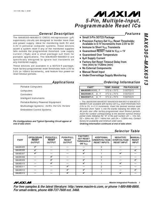
MAX6305中文资料
For free samples & the latest literature: , or phone 1-800-998-8800.For small orders, phone 408-737-7600 ext. 3468.General DescriptionThe MAX6305–MAX6313 CMOS microprocessor (µP)supervisory circuits are designed to monitor more than one power supply. Ideal for monitoring both 5V and 3.3V in personal computer systems, these devicesFeatureso Small 5-Pin SOT23 Packageo Precision Factory-Set V CC Reset Thresholds;Available in 0.1V Increments from 2.5V to 5V o Immune to Short V TransientsMAX6305–MAX63135-Pin, Multiple-Input,Programmable Reset ICs________________________________________________________________Maxim Integrated Products 119-1145; Rev 1; 8/98M A X 6305–M A X 63135-Pin, Multiple-Input, Programmable Reset ICs 2_______________________________________________________________________________________ABSOLUTE MAXIMUM RATINGSELECTRICAL CHARACTERISTICSV CC = +2.5V to +5.5V for the MAX6305/MAX6308/MAX6311, V CC = (V TH + 2.5%) to +5.5V for the MAX6306/MAX6307/MAX6309/MAX6310/MAX6312/MAX6313; T A = 0°C to +70°C; unless otherwise noted. Typical values are at T A = +25°C.)Stresses beyond those listed under “Absolute Maximum Ratings” may cause permanent damage to the device. These are stress ratings only, and functional operation of the device at these or any other conditions beyond those indicated in the operational sections of the specifications is not implied. Exposure to absolute maximum rating conditions for extended periods may affect device reliability.V CC ...........................................................................-0.3V to +6V All Other Pins..............................................-0.3V to (V CC + 0.3V)Input/Output Current, All Pins.............................................20mA Rate of Rise, V CC ............................................................100V/µsContinuous Power Dissipation (T A = +70°C)SOT23-5 (derate 7.1mW/°C above +70°C).................571mW Operating Temperature Range...............................0°C to +70°C Storage Temperature Range.............................-65°C to +160°C Lead Temperature (soldering, 10sec).............................+300°CMAX6305–MAX63135-Pin, Multiple-Input, Programmable Reset ICs_______________________________________________________________________________________3ELECTRICAL CHARACTERISTICS (continued)(V CC = +2.5V to +5.5V for the MAX6305/MAX6308/MAX6311, V CC = (V TH + 2.5%) to +5.5V for the MAX6306/MAX6307/MAX6309/MAX6310/MAX6312/MAX6313; T A = 0°C to +70°C; unless otherwise noted. Typical values are at T A = +25°C.)Note 1: The MAX6305/MAX6308/MAX6311 switch from undervoltage reset to normal operation between 1.5V < V CC < 2.5V.Note 2: The MAX6306/MAX6307/MAX6309/MAX6310/MAX6312/MAX6313 monitor V CC through an internal factory-trimmed voltagedivider, which programs the nominal reset threshold. Factory-trimmed reset thresholds are available in approximately 100mV increments from 2.5V to 5V (Table 1).M A X 6305–M A X 63135-Pin, Multiple-Input, Programmable Reset ICs 4_________________________________________________________________________________________________________________________________Typical Operating Characteristics(V CC = +5V, T A = +25°C, unless otherwise noted.)5.05.56.06.57.07.58.08.59.09.5-60-40-2020406080100SUPPLY CURRENT vs. TEMPERATURETEMPERATURE (°C)S U P P L Y C U R R E N T (µA )01020304050607080-60-40-2020406080100V CC FALLING PROPAGATION DELAYvs. TEMPERATURETEMPERATURE (°C)P R O P A G A T I O N D E L A Y (n s )010203040506070-60-40-20020406080100OVRST IN RISING PROPAGATION DELAY vs. TEMPERATURE (OVERVOLTAGE RESET INPUT)TEMPERATURE (°C)P R O P A G A T I O N D E L A Y (n s )020406080100120-60-40-2020406080100RST IN_ FALLING PROPAGATION DELAY vs. TEMPERATURETEMPERATURE (°C)R S T I N _ P R O P A G A T I O N D E L A Y (n s )104001200800MAXIMUM TRANSIENT DURATION vs.V CC RESET THRESHOLD OVERDRIVE10OVERDRIVE, V TH - V CC (mV)T R A N S I E N T D U R A T I O N (µs )100100010,0000.900.920.940.960.981.001.021.041.061.081.10-60-40-20020406080100RESET TIMEOUT vs. TEMPERATURE6305 T O C 05TEMPERATURE (°C)N O R M A L I Z E D R E S E T T I M E O U T0.9900.9920.9940.9960.9981.0001.0021.0041.0061.0081.010-60-40-2020406080100RESET THRESHOLD vs. TEMPERATURE6305 T O C 06TEMPERATURE (°C)N O R M A L I Z E D R E S E T T H R E S H O L D (V /V )104001200800MAXIMUM TRANSIENT DURATION vs.OVRST IN THRESHOLD OVERDRIVE10OVERDRIVE, V OVRST IN - V REF (mV)T R A N S I E N T D U R A T I O N (µs )100100010,000104001200800MAXIMUM TRANSIENT DURATION vs.RST IN_ THRESHOLD OVERDRIVE10OVERDRIVE, V REF - V RST IN (mV)T R A N S I E N T D U R A T I O N (µs )100100010,000_______________Detailed DescriptionThe MAX6305–MAX6313 CMOS microprocessor (µP)supervisory circuits are designed to monitor more than one power supply and issue a system reset when any monitored supply falls out of regulation. The MAX6305/MAX6308/MAX6311 have two adjustable undervoltage reset inputs (RST IN1 and RST IN2). The MAX6306/MAX6307/MAX6309/MAX6310/MAX6312/MAX6313 mon-itor V CC through an internal, factory-trimmed voltage divider. The MAX6306/MAX6309/MAX6312 have, in addition, an adjustable undervoltage reset input and a manual-reset input. The internal voltage divider sets the reset threshold as specified in the device part number (Table 1). The MAX6307/MAX6310/ MAX6313 feature an adjustable undervoltage reset input (RST IN) and an adjustable overvoltage reset input (OVRST IN) in addition to the factory-trimmed reset threshold on the V CC moni-tor. Program the adjustable reset inputs with an external resistor divider (see Adjustable Reset Inputs section).Reset OutputsA µP’s reset input starts the µP in a known state. These µP supervisory circuits assert reset to prevent code-execution errors during power-up, power-down, or brownout conditions.RESET (MAX6305–MAX6310) and RESET (MAX6311/MAX6312/MAX6313) are guaranteed to be asserted at a valid logic level for V CC > 1V (see Electrical Characteristics ). Once all monitored voltages exceed their programmed reset thresholds, an internal timer keeps reset asserted for the reset timeout period (t RP );after this interval, reset deasserts.If a brownout condition occurs (any or all monitored volt-ages dip outside their programmed reset threshold),reset asserts (RESET goes high; RESET goes low). Any time any of the monitored voltages dip below their reset threshold, the internal timer resets to zero and reset asserts. The internal timer starts when all of the moni-tored voltages return above their reset thresholds, and reset remains asserted for a reset timeout period. The MAX6305/MAX6306/MAX6307 feature an active-low,MAX6305–MAX63135-Pin, Multiple-Input, Programmable Reset ICs_______________________________________________________________________________________5______________________________________________________________Pin DescriptionM A X 6305–M A X 6313open-drain, N-channel output. The MAX6308/MAX6309/MAX6310 feature an active-low, complementary output structure that both sinks and sources current, and the MAX6311/MAX6312/MAX6313 have an active-high com-plementary reset output.The MAX6305/MAX6308/MAX6311 switch from under-voltage lockout operation to normal operation between 1.5V < V CC < 2.5V. Below 1.5V, V CC undervoltage-lockout mode asserts RESET . Above 2.5V, V CC normal-operation mode asserts reset if RST IN_ falls below the RST IN_ threshold.Manual-Reset Input(MAX6306/MAX6309/MAX6312)Many µP-based products require manual-reset capability,allowing an operator or external logic circuitry to initiate a reset. A logic low on MR asserts reset. Reset remains asserted while MR is low, and for a reset active timeout period (t RP ) after MR returns high. This input has an inter-nal 63.5k Ωpull-up resistor, so it can be left open if it is not used. MR can be driven with TTL-logic levels in 5V sys-tems, with CMOS-logic levels in 3V systems, or with open-drain/collector output devices. Connect a normally open momentary switch from MR to GND to create a manual-reset function; external debounce circuitry is not required.If MR is driven from long cables or if the device is used in a noisy environment, connecting a 0.1µF capacitor from MR to ground provides additional noise immunity.The MR pin has internal ESD-protection circuitry that may be forward biased under certain conditions, drawing excessive current. For example, assume the circuitry driv-ing MR uses a +5V supply other than V CC . If V CC drops or browns out lower than +4.7V, MR ’s absolute maximum rat-ing is violated (-0.3V to (V CC + 0.3V)), and undesirable current flows through the ESD structure from MR to V CC .To avoid this, it is recommended that the supply for the MR pin be the same as the supply monitored by V CC . In this way, the voltage at MR will not exceed V CC .Adjustable Reset InputsThe MAX6305–MAX6313 each have one or more reset inputs (RST IN_ /OVRST IN). These inputs are com-pared to the internal reference voltage (Figure 1).Connect a resistor voltage divider to RST IN_ such that V RST IN_falls below V RSTH (1.23V) when the monitored voltage (V IN ) falls below the desired reset threshold (V TH ) (Figure 2). Calculate the desired reset voltage with the following formula:R1 + R2V TH = ________x V RSTHR25-Pin, Multiple-Input, Programmable Reset ICs 6_______________________________________________________________________________________Figure 1. Functional DiagramMAX6305–MAX63135-Pin, Multiple-Input, Programmable Reset ICs_______________________________________________________________________________________7The ±25nA max input leakage current allows resistors on the order of megohms. Choose the pull-up resistor in the divider to minimize the error due to the input leakage cur-rent. The error term in the calculated threshold is simply:±25nA x R1If you choose R1 to be 1M Ω, the resulting error is ±25 x 10-9x 1 x 106= ±25mV.Like the V CC voltage monitors on the MAX6306/MAX6307/MAX6309/MAX6310/MAX6312/MAX6313, the RST IN_inputs (when used with a voltage divider) are designed to ignore fast voltage transients. Increase the noise immunity by connecting a capacitor on the order of 0.1µF between RST IN and GND (Figure 2). This creates a single-pole lowpass filter with a corner frequency given by:f = (1/2π) / (R1 + R2)(R1 x R2 x C)For example, if R1 = 1M Ωand R2 = 1.6M Ω, adding a 0.1µF capacitor from RST IN_ to ground results in a lowpass corner frequency of f = 2.59Hz. Note that adding capacitance to RST IN slows the circuit’s overall response time.__________Applications InformationInterfacing to µPs with Bidirectional Reset PinsSince the RESET output on the MAX6305/MAX6306/MAX6307 is open drain, these devices interface easily with µPs that have bidirectional reset pins, such as the Motorola 68HC11. Connecting the µP supervisor’s RESET output directly to the microcontroller’s RESET pin with a single pull-up resistor allows either device to assert reset (Figure 3).Negative-Going V CC TransientsIn addition to issuing a reset to the µP during power-up,power-down, and brownout conditions, these devices are relatively immune to short-duration, negative-going V CC transients (glitches).The Typical Operating Characteristics show the Maximum Transient Duration vs. V CC Reset Threshold Overdrive, for which reset pulses are not generated.The graph was produced using negative-going pulses,starting at V TH max, and ending below the pro-grammed reset threshold by the magnitude indicated (reset threshold overdrive). The graph shows the maxi-mum pulse width that a negative-going V CC transient may typically have without causing a reset pulse to be issued. As the amplitude of the transient increases (i.e.,goes farther below the reset threshold), the maximum allowable pulse width decreases.RST IN_/OVRST IN are also immune to negative/positive-going transients (see Typical Operating Characteristics ).A 0.1µF bypass capacitor mounted close to the RST IN_,OVRST IN, and/or the V CC pin provides additional tran-sient immunity.Ensuring a Valid RESET /RESETOutput Down to V CC = 0VWhen V CC falls below 1V, push/pull structured RESET /RESET current sinking (or sourcing) capabilities decrease drastically. High-impedance CMOS-logic inputs connected to RESET can drift to undetermined voltages. This presents no problem in most applica-tions, since most µPs and other circuitry do not operate with V CC below 1V. In those applications where RESET must be valid down to 0V, adding a pull-down resistor between RESET and ground sinks any stray leakageFigure 2. Increasing Noise ImmunityFigure 3. Interfacing to µPs with Bidirectional Reset I/Ocurrents, holding RESET low (Figure 4). The pull-down resistor’s value is not critical; 100k Ωis large enough not to load RESET and small enough to pull RESET to ground. For applications where RESET must be valid to V CC , a 100k Ωpull-up resistor between RESET and V CC will hold RESET high when V CC falls below 1V (Figure 5).Since the MAX6305/MAX6306/MAX6307 have open-drain, active-low outputs, they typically use a pull-up resistor. With these devices and under these conditions (V CC < 1V), RESET will most likely not maintain an active condition, but will drift toward a nonactive level due to the pull-up resistor and the RESET output’s reduction in sinking capability. These devices are not recommended for applications that require a valid RESET output below 1V.* Factory-trimmed reset thresholds are available in approximately 100mV increments with a ±1.5% room-temperature variance.M A X 6305–M A X 63135-Pin, Multiple-Input, Programmable Reset ICs 8_______________________________________________________________________________________Figure 4. Ensuring RESET Valid to V CC = 0VFigure 5. Ensuring RESET Valid to V CC = 0VTable 1. Factory-Trimmed Reset Thresholds *MAX6305UK00D1-T ABAK MAX6306UK41D3-T ABCA MAX6306UK30D1-T ABDQ MAX6307UK46D3-T ABFG MAX6305UK00D2-T ABAL MAX6306UK41D4-T ABCB MAX6306UK30D2-T ABDR MAX6307UK46D4-T ABFH MAX6305UK00D3-T ABAM MAX6306UK40D1-T ABCC MAX6306UK30D3-T ABDS MAX6307UK45D1-T ABFI MAX6305UK00D4-T ABAN MAX6306UK40D2-T ABCD MAX6306UK30D4-T ABDT MAX6307UK45D2-T ABFJ MAX6306UK50D1-T ABAO MAX6306UK40D3-T ABCE MAX6306UK29D1-T ABDU MAX6307UK45D3-T ABFK MAX6306UK50D2-T ABAP MAX6306UK40D4-T ABCF MAX6306UK29D2-T ABDV MAX6307UK45D4-T ABFL MAX6306UK50D3-T ABAQ MAX6306UK39D1-T ABCG MAX6306UK29D3-T ABDW MAX6307UK44D1-T ABFM MAX6306UK50D4-T ABAR MAX6306UK39D2-T ABCH MAX6306UK29D4-T ABDX MAX6307UK44D2-T ABFN MAX6306UK49D1-T ABAS MAX6306UK39D3-T ABCI MAX6306UK28D1-T ABDY MAX6307UK44D3-T ABFO MAX6306UK49D2-T ABAT MAX6306UK39D4-T ABCJ MAX6306UK28D2-T ABDZ MAX6307UK44D4-T ABFP MAX6306UK49D3-T ABAU MAX6306UK38D1-T ABCK MAX6306UK28D3-T ABEA MAX6307UK43D1-T ABFQ MAX6306UK49D4-T ABAV MAX6306UK38D2-T ABCL MAX6306UK28D4-T ABEB MAX6307UK43D2-T ABFR MAX6306UK48D1-T ABAW MAX6306UK38D3-T ABCM MAX6306UK27D1-T ABEC MAX6307UK43D3-T ABFS MAX6306UK48D2-T ABAX MAX6306UK38D4-T ABCN MAX6306UK27D2-T ABED MAX6307UK43D4-T ABFT MAX6306UK48D3-T ABAY MAX6306UK37D1-T ABCO MAX6306UK27D3-T ABEE MAX6307UK42D1-T ABFU MAX6306UK48D4-T ABAZ MAX6306UK37D2-T ABCP MAX6306UK27D4-T ABEF MAX6307UK42D2-T ABFV MAX6306UK47D1-T ABBA MAX6306UK37D3-T ABCQ MAX6306UK26D1-T ABEG MAX6307UK42D3-T ABFW MAX6306UK47D2-T ABBB MAX6306UK37D4-T ABCR MAX6306UK26D2-T ABEH MAX6307UK42D4-T ABFX MAX6306UK47D3-T ABBC MAX6306UK36D1-T ABCS MAX6306UK26D3-T ABEI MAX6307UK41D1-T ABFY MAX6306UK47D4-T ABBD MAX6306UK36D2-T ABCT MAX6306UK26D4-T ABEJ MAX6307UK41D2-T ABFZ MAX6306UK46D1-T ABBE MAX6306UK36D3-T ABCU MAX6306UK25D1-T ABEK MAX6307UK41D3-T ABGA MAX6306UK46D2-T ABBF MAX6306UK36D4-T ABCV MAX6306UK25D2-T ABEL MAX6307UK41D4-T ABGB MAX6306UK46D3-T ABBG MAX6306UK35D1-T ABCW MAX6306UK25D3-T ABEM MAX6307UK40D1-T ABGC MAX6306UK46D4-T ABBH MAX6306UK35D2-T ABCX MAX6306UK25D4-T ABEN MAX6307UK40D2-T ABGD MAX6306UK45D1-T ABBI MAX6306UK35D3-T ABCY MAX6307UK50D1-T ABEO MAX6307UK40D3-T ABGE MAX6306UK45D2-T ABBJ MAX6306UK35D4-T ABCZ MAX6307UK50D2-T ABEP MAX6307UK40D4-T ABGF MAX6306UK45D3-T ABBK MAX6306UK34D1-T ABDA MAX6307UK50D3-T ABEQ MAX6307UK39D1-T ABGG MAX6306UK45D4-T ABBL MAX6306UK34D2-T ABDB MAX6307UK50D4-T ABER MAX6307UK39D2-T ABGH MAX6306UK44D1-T ABBM MAX6306UK34D3-T ABDC MAX6307UK49D1-T ABES MAX6307UK39D3-T ABGI MAX6306UK44D2-T ABBN MAX6306UK34D4-T ABDD MAX6307UK49D2-T ABET MAX6307UK39D4-T ABGJ MAX6306UK44D3-T ABBO MAX6306UK33D1-T ABDE MAX6307UK49D3-T ABEU MAX6307UK38D1-T ABGK MAX6306UK44D4-T ABBP MAX6306UK33D2-T ABDF MAX6307UK49D4-T ABEV MAX6307UK38D2-T ABGL MAX6306UK43D1-T ABBQ MAX6306UK33D3-T ABDG MAX6307UK48D1-T ABEW MAX6307UK38D3-T ABGM MAX6306UK43D2-T ABBR MAX6306UK33D4-T ABDH MAX6307UK48D2-T ABEX MAX6307UK38D4-T ABGN MAX6306UK43D3-T ABBS MAX6306UK32D1-T ABDI MAX6307UK48D3-T ABEY MAX6307UK37D1-T ABGO MAX6306UK43D4-T ABBT MAX6306UK32D2-T ABDJ MAX6307UK48D4-T ABEZ MAX6307UK37D2-T ABGP MAX6306UK42D1-T ABBU MAX6306UK32D3-T ABDK MAX6307UK47D1-T ABFA MAX6307UK37D3-T ABGQ MAX6306UK42D2-T ABBV MAX6306UK32D4-T ABDL MAX6307UK47D2-T ABFB MAX6307UK37D4-T ABGR MAX6306UK42D3-T ABBW MAX6306UK31D1-T ABDM MAX6307UK47D3-T ABFC MAX6307UK36D1-T ABGS MAX6306UK42D4-T ABBX MAX6306UK31D2-T ABDN MAX6307UK47D4-T ABFD MAX6307UK36D2-T ABGT MAX6306UK41D1-T ABBY MAX6306UK31D3-T ABDO MAX6307UK46D1-T ABFE MAX6307UK36D3-T ABGU MAX6306UK41D2-TABBZMAX6306UK31D4-TABDPMAX6307UK46D2-TABFFMAX6307UK36D4-TABGVMAX6305–MAX63135-Pin, Multiple-Input, Programmable Reset ICs_______________________________________________________________________________________9Table 2. Device Marking CodesDEVICECODE DEVICECODE DEVICECODE DEVICECODEM A X 6305–M A X 63135-Pin, Multiple-Input, Programmable Reset ICs 10______________________________________________________________________________________Table 2. Device Marking Codes (continued)MAX6307UK35D1-T ABGW MAX6307UK25D3-T ABIM MAX6309UK41D1-T ABKC MAX6309UK31D3-T ABLS MAX6307UK35D2-T ABGX MAX6307UK25D4-T ABIN MAX6309UK41D2-T ABKD MAX6309UK31D4-T ABLT MAX6307UK35D3-T ABGY MAX6308UK00D1-T ABIO MAX6309UK41D3-T ABKE MAX6309UK30D1-T ABLU MAX6307UK35D4-T ABGZ MAX6308UK00D2-T ABIP MAX6309UK41D4-T ABKF MAX6309UK30D2-T ABLV MAX6307UK34D1-T ABHA MAX6308UK00D3-T ABIQ MAX6309UK40D1-T ABKG MAX6309UK30D3-T ABLW MAX6307UK34D2-T ABHB MAX6308UK00D4-T ABIR MAX6309UK40D2-T ABKH MAX6309UK30D4-T ABLX MAX6307UK34D3-T ABHC MAX6309UK50D1-T ABIS MAX6309UK40D3-T ABKI MAX6309UK29D1-T ABLY MAX6307UK34D4-T ABHD MAX6309UK50D2-T ABIT MAX6309UK40D4-T ABKJ MAX6309UK29D2-T ABLZ MAX6307UK33D1-T ABHE MAX6309UK50D3-T ABIU MAX6309UK39D1-T ABKK MAX6309UK29D3-T ABMA MAX6307UK33D2-T ABHF MAX6309UK50D4-T ABIV MAX6309UK39D2-T ABKL MAX6309UK29D4-T ABMB MAX6307UK33D3-T ABHG MAX6309UK49D1-T ABIW MAX6309UK39D3-T ABKM MAX6309UK28D1-T ABMC MAX6307UK33D4-T ABHH MAX6309UK49D2-T ABIX MAX6309UK39D4-T ABKN MAX6309UK28D2-T ABMD MAX6307UK32D1-T ABHI MAX6309UK49D3-T ABIY MAX6309UK38D1-T ABKO MAX6309UK28D3-T ABME MAX6307UK32D2-T ABHJ MAX6309UK49D4-T ABIZ MAX6309UK38D2-T ABKP MAX6309UK28D4-T ABMF MAX6307UK32D3-T ABHK MAX6309UK48D1-T ABJA MAX6309UK38D3-T ABKQ MAX6309UK27D1-T ABMG MAX6307UK32D4-T ABHL MAX6309UK48D2-T ABJB MAX6309UK38D4-T ABKR MAX6309UK27D2-T ABMH MAX6307UK31D1-T ABHM MAX6309UK48D3-T ABJC MAX6309UK37D1-T ABKS MAX6309UK27D3-T ABMI MAX6307UK31D2-T ABHN MAX6309UK48D4-T ABJD MAX6309UK37D2-T ABKT MAX6309UK27D4-T ABMJ MAX6307UK31D3-T ABHO MAX6309UK47D1-T ABJE MAX6309UK37D3-T ABKU MAX6309UK26D1-T ABMK MAX6307UK31D4-T ABHP MAX6309UK47D2-T ABJF MAX6309UK37D4-T ABKV MAX6309UK26D2-T ABML MAX6307UK30D1-T ABHQ MAX6309UK47D3-T ABJG MAX6309UK36D1-T ABKW MAX6309UK26D3-T ABMM MAX6307UK30D2-T ABHR MAX6309UK47D4-T ABJH MAX6309UK36D2-T ABKX MAX6309UK26D4-T ABMN MAX6307UK30D3-T ABHS MAX6309UK46D1-T ABJI MAX6309UK36D3-T ABKY MAX6309UK25D1-T ABMO MAX6307UK30D4-T ABHT MAX6309UK46D2-T ABJJ MAX6309UK36D4-T ABKZ MAX6309UK25D2-T ABMP MAX6307UK29D1-T ABHU MAX6309UK46D3-T ABJK MAX6309UK35D1-T ABLA MAX6309UK25D3-T ABMQ MAX6307UK29D2-T ABHV MAX6309UK46D4-T ABJL MAX6309UK35D2-T ABLB MAX6309UK25D4-T ABMR MAX6307UK29D3-T ABHW MAX6309UK45D1-T ABJM MAX6309UK35D3-T ABLC MAX6310UK50D1-T ABMS MAX6307UK29D4-T ABHX MAX6309UK45D2-T ABJN MAX6309UK35D4-T ABLD MAX6310UK50D2-T ABMT MAX6307UK28D1-T ABHY MAX6309UK45D3-T ABJO MAX6309UK34D1-T ABLE MAX6310UK50D3-T ABMU MAX6307UK28D2-T ABHZ MAX6309UK45D4-T ABJP MAX6309UK34D2-T ABLF MAX6310UK50D4-T ABMV MAX6307UK28D3-T ABIA MAX6309UK44D1-T ABJQ MAX6309UK34D3-T ABLG MAX6310UK49D1-T ABMW MAX6307UK28D4-T ABIB MAX6309UK44D2-T ABJR MAX6309UK34D4-T ABLH MAX6310UK49D2-T ABMX MAX6307UK27D1-T ABIC MAX6309UK44D3-T ABJS MAX6309UK33D1-T ABLI MAX6310UK49D3-T ABMY MAX6307UK27D2-T ABID MAX6309UK44D4-T ABJT MAX6309UK33D2-T ABLJ MAX6310UK49D4-T ABMZ MAX6307UK27D3-T ABIE MAX6309UK43D1-T ABJU MAX6309UK33D3-T ABLK MAX6310UK48D1-T ABNA MAX6307UK27D4-T ABIF MAX6309UK43D2-T ABJV MAX6309UK33D4-T ABLL MAX6310UK48D2-T ABNB MAX6307UK26D1-T ABIG MAX6309UK43D3-T ABJW MAX6309UK32D1-T ABLM MAX6310UK48D3-T ABNC MAX6307UK26D2-T ABIH MAX6309UK43D4-T ABJX MAX6309UK32D2-T ABLN MAX6310UK48D4-T ABND MAX6307UK26D3-T ABII MAX6309UK42D1-T ABJY MAX6309UK32D3-T ABLO MAX6310UK47D1-T ABNE MAX6307UK26D4-T ABIJ MAX6309UK42D2-T ABJZ MAX6309UK32D4-T ABLP MAX6310UK47D2-T ABNF MAX6307UK25D1-T ABIK MAX6309UK42D3-T ABKA MAX6309UK31D1-T ABLQ MAX6310UK47D3-T ABNG MAX6307UK25D2-TABILMAX6309UK42D4-TABKBMAX6309UK31D2-TABLRMAX6310UK47D4-TABNHDEVICECODE DEVICECODE DEVICECODE DEVICECODEMAX6305–MAX6313Programmable Reset ICs______________________________________________________________________________________11Table 2. Device Marking Codes (continued)MAX6310UK46D1-T ABNI MAX6310UK36D3-T ABOY MAX6310UK25D1-T ABQO MAX6312UK42D3-T ABSE MAX6310UK46D2-T ABNJ MAX6310UK36D4-T ABOZ MAX6310UK25D2-T ABQP MAX6312UK42D4-T ABSF MAX6310UK46D3-T ABNK MAX6310UK35D1-T ABPA MAX6310UK25D3-T ABQQ MAX6312UK41D1-T ABSG MAX6310UK46D4-T ABNL MAX6310UK35D2-T ABPB MAX6310UK25D4-T ABQR MAX6312UK41D2-T ABSH MAX6310UK45D1-T ABNM MAX6310UK35D3-T ABPC MAX6311UK00D1-T ABQS MAX6312UK41D3-T ABSI MAX6310UK45D2-T ABNN MAX6310UK35D4-T ABPD MAX6311UK00D2-T ABQT MAX6312UK41D4-T ABSJ MAX6310UK45D3-T ABNO MAX6310UK34D1-T ABPE MAX6311UK00D3-T ABQU MAX6312UK40D1-T ABSK MAX6310UK45D4-T ABNP MAX6310UK34D2-T ABPF MAX6311UK00D4-T ABQV MAX6312UK40D2-T ABSL MAX6310UK44D1-T ABNQ MAX6310UK34D3-T ABPG MAX6311UK50D1-T ABQW MAX6312UK40D3-T ABSM MAX6310UK44D2-T ABNR MAX6310UK34D4-T ABPH MAX6312UK50D2-T ABQX MAX6312UK40D4-T ABSN MAX6310UK44D3-T ABNS MAX6310UK33D1-T ABPI MAX6312UK50D3-T ABQY MAX6312UK39D1-T ABSO MAX6310UK44D4-T ABNT MAX6310UK33D2-T ABPJ MAX6312UK50D4-T ABQZ MAX6312UK39D2-T ABSP MAX6310UK43D1-T ABNU MAX6310UK33D3-T ABPK MAX6312UK49D1-T ABRA MAX6312UK39D3-T ABSQ MAX6310UK43D2-T ABNV MAX6310UK33D4-T ABPL MAX6312UK49D2-T ABRB MAX6312UK39D4-T ABSR MAX6310UK43D3-T ABNW MAX6310UK32D1-T ABPM MAX6312UK49D3-T ABRC MAX6312UK38D1-T ABSS MAX6310UK43D4-T ABNX MAX6310UK32D2-T ABPN MAX6312UK49D4-T ABRD MAX6312UK38D2-T ABST MAX6310UK42D1-T ABNY MAX6310UK32D3-T ABPO MAX6312UK48D1-T ABRE MAX6312UK38D3-T ABSU MAX6310UK42D2-T ABNZ MAX6310UK32D4-T ABPP MAX6312UK48D2-T ABRF MAX6312UK38D4-T ABSV MAX6310UK42D3-T ABOA MAX6310UK31D1-T ABPQ MAX6312UK48D3-T ABRG MAX6312UK37D1-T ABSW MAX6310UK42D4-T ABOB MAX6310UK31D2-T ABPR MAX6312UK48D4-T ABRH MAX6312UK37D2-T ABSX MAX6310UK41D1-T ABOC MAX6310UK31D3-T ABPS MAX6312UK47D1-T ABRI MAX6312UK37D3-T ABSY MAX6310UK41D2-T ABOD MAX6310UK31D4-T ABPT MAX6312UK47D2-T ABRJ MAX6312UK37D4-T ABSZ MAX6310UK41D3-T ABOE MAX6310UK30D1-T ABPU MAX6312UK47D3-T ABRK MAX6312UK36D1-T ABTA MAX6310UK41D4-T ABOF MAX6310UK30D2-T ABPV MAX6312UK47D4-T ABRL MAX6312UK36D2-T ABTB MAX6310UK40D1-T ABOG MAX6310UK30D3-T ABPW MAX6312UK46D1-T ABRM MAX6312UK36D3-T ABTC MAX6310UK40D2-T ABOH MAX6310UK30D4-T ABPX MAX6312UK46D2-T ABRN MAX6312UK36D4-T ABTD MAX6310UK40D3-T ABOI MAX6310UK29D1-T ABPY MAX6312UK46D3-T ABRO MAX6312UK35D1-T ABTE MAX6310UK40D4-T ABOJ MAX6310UK29D2-T ABPZ MAX6312UK46D4-T ABRP MAX6312UK35D2-T ABTF MAX6310UK39D1-T ABOK MAX6310UK29D3-T ABQA MAX6312UK45D1-T ABRQ MAX6312UK35D3-T ABTG MAX6310UK39D2-T ABOL MAX6310UK29D4-T ABQB MAX6312UK45D2-T ABRR MAX6312UK35D4-T ABTH MAX6310UK39D3-T ABOM MAX6310UK28D1-T ABQC MAX6312UK45D3-T ABRS MAX6312UK34D1-T ABTI MAX6310UK39D4-T ABON MAX6310UK28D2-T ABQD MAX6312UK45D4-T ABRT MAX6312UK34D2-T ABTJ MAX6310UK38D1-T ABOO MAX6310UK28D3-T ABQE MAX6312UK44D1-T ABRU MAX6312UK34D3-T ABTK MAX6310UK38D2-T ABOP MAX6310UK28D4-T ABQF MAX6312UK44D2-T ABRV MAX6312UK34D4-T ABTL MAX6310UK38D3-T ABOQ MAX6310UK27D1-T ABQG MAX6312UK44D3-T ABRW MAX6312UK33D1-T ABTM MAX6310UK38D4-T ABOR MAX6310UK27D2-T ABQH MAX6312UK44D4-T ABRX MAX6312UK33D2-T ABTN MAX6310UK37D1-T ABOS MAX6310UK27D3-T ABQI MAX6312UK43D1-T ABRY MAX6312UK33D3-T ABTO MAX6310UK37D2-T ABOT MAX6310UK27D4-T ABQJ MAX6312UK43D2-T ABRZ MAX6312UK33D4-T ABTP MAX6310UK37D3-T ABOU MAX6310UK26D1-T ABQK MAX6312UK43D3-T ABSA MAX6312UK32D1-T ABTQ MAX6310UK37D4-T ABOV MAX6310UK26D2-T ABQL MAX6312UK43D4-T ABSB MAX6312UK32D2-T ABTR MAX6310UK36D1-T ABOW MAX6310UK26D3-T ABQM MAX6312UK42D1-T ABSC MAX6312UK32D3-T ABTS MAX6310UK36D2-TABOXMAX6310UK26D4-TABQNMAX6312UK42D2-TABSDMAX6312UK32D4-TABTTDEVICECODE DEVICECODE DEVICECODE DEVICECODEM A X 6305–M A X 6313Programmable Reset ICs 12______________________________________________________________________________________Table 2. Device Marking Codes (continued)MAX6313UK49D2-T ABVB MAX6313UK49D3-T ABVC MAX6313UK49D4-T ABVD MAX6313UK48D1-T ABVE MAX6313UK48D2-T ABVF MAX6313UK48D3-T ABVG MAX6313UK48D4-T ABVH MAX6313UK47D1-T ABVI MAX6313UK47D2-T ABVJ MAX6313UK47D3-T ABVK MAX6313UK47D4-T ABVL MAX6313UK46D1-T ABVM MAX6313UK46D2-T ABVN MAX6313UK46D3-T ABVO MAX6313UK46D4-T ABVP MAX6313UK45D1-T ABVQ MAX6313UK45D2-T ABVR MAX6313UK45D3-T ABVS MAX6313UK45D4-T ABVT MAX6313UK44D1-T ABVU MAX6313UK44D2-T ABVV MAX6313UK44D3-T ABVW MAX6313UK44D4-T ABVX MAX6313UK43D1-T ABVY MAX6313UK43D2-T ABVZ MAX6313UK43D3-T ABWA MAX6313UK43D4-T ABWB MAX6313UK42D1-T ABWC MAX6313UK42D2-T ABWD MAX6313UK42D3-T ABWE MAX6313UK42D4-T ABWF MAX6313UK41D1-T ABWG MAX6313UK41D2-TABWHDEVICECODE DEVICECODE DEVICECODE DEVICECODE MAX6313UK33D4-T ABXP MAX6313UK32D1-T ABXQ MAX6313UK32D2-T ABXR MAX6313UK32D3-T ABXS MAX6313UK32D4-T ABXT MAX6313UK31D1-T ABXU MAX6313UK31D2-T ABXV MAX6313UK31D3-T ABXW MAX6313UK31D4-T ABXX MAX6313UK30D1-T ABXY MAX6313UK30D2-T ABXZ MAX6313UK30D3-T ABYA MAX6313UK30D4-T ABYB MAX6313UK29D1-T ABYC MAX6313UK29D2-T ABYD MAX6313UK29D3-T ABYE MAX6313UK29D4-T ABYF MAX6313UK28D1-T ABYG MAX6313UK28D2-T ABYH MAX6313UK28D3-T ABYI MAX6313UK28D4-T ABYJ MAX6313UK27D1-T ABYK MAX6313UK27D2-T ABYL MAX6313UK27D3-T ABYM MAX6313UK27D4-T ABYN MAX6313UK26D1-T ABYO MAX6313UK26D2-T ABYP MAX6313UK26D3-T ABYQ MAX6313UK26D4-T ABYR MAX6313UK25D1-T ABYS MAX6313UK25D2-T ABYT MAX6313UK25D3-T ABYU MAX6313UK25D4-TABYVMAX6313UK41D3-T ABWI MAX6313UK41D4-T ABWJ MAX6313UK40D1-T ABWK MAX6313UK40D2-T ABWL MAX6313UK40D3-T ABWM MAX6313UK40D4-T ABWN MAX6313UK39D1-T ABWO MAX6313UK39D2-T ABWP MAX6313UK39D3-T ABWQ MAX6313UK39D4-T ABWR MAX6313UK38D1-T ABWS MAX6313UK38D2-T ABWT MAX6313UK38D3-T ABWU MAX6313UK38D4-T ABWV MAX6313UK37D1-T ABWW MAX6313UK37D2-T ABWX MAX6313UK37D3-T ABWY MAX6313UK37D4-T ABWZ MAX6313UK36D1-T ABXA MAX6313UK36D2-T ABXB MAX6313UK36D3-T ABXC MAX6313UK36D4-T ABXD MAX6313UK35D1-T ABXE MAX6313UK35D2-T ABXF MAX6313UK35D3-T ABXG MAX6313UK35D4-T ABXH MAX6313UK34D1-T ABXI MAX6313UK34D2-T ABXJ MAX6313UK34D3-T ABXK MAX6313UK34D4-T ABXL MAX6313UK33D1-T ABXM MAX6313UK33D2-T ABXN MAX6313UK33D3-TABXOMAX6312UK31D1-T ABTU MAX6312UK31D2-T ABTV MAX6312UK31D3-T ABTW MAX6312UK31D4-T ABTX MAX6312UK30D1-T ABTY MAX6312UK30D2-T ABTZ MAX6312UK30D3-T ABUA MAX6312UK30D4-T ABUB MAX6312UK29D1-T ABUC MAX6312UK29D2-T ABUD MAX6312UK29D3-T ABUE MAX6312UK29D4-T ABUF MAX6312UK28D1-T ABUG MAX6312UK28D2-T ABUH MAX6312UK28D3-T ABUI MAX6312UK28D4-T ABUJ MAX6312UK27D1-T ABUK MAX6312UK27D2-T ABUL MAX6312UK27D3-T ABUM MAX6312UK27D4-T ABUN MAX6312UK26D1-T ABUO MAX6312UK26D2-T ABUP MAX6312UK26D3-T ABUQ MAX6312UK26D4-T ABUR MAX6312UK25D1-T ABUS MAX6312UK25D2-T ABUT MAX6312UK25D3-T ABUU MAX6312UK25D4-T ABUV MAX6313UK50D1-T ABUW MAX6313UK50D2-T ABUX MAX6313UK50D3-T ABUY MAX6313UK50D4-T ABUZ MAX6313UK49D1-TABVA。
bl6306中文规格书

bl6306中文规格书BL6306中文规格书BL6306是一款先进的智能手机,具有多项出色的功能和性能。
本文将介绍BL6306的规格和特点,并详细阐述其核心功能、设计和性能。
一、外观设计BL6306采用精致的外观设计,配备6.3英寸全高清屏幕,分辨率达到1080p,带来清晰、细腻的视觉体验。
机身采用金属材质,手感舒适,同时还具有防刮、防指纹等特点,保持机身长久的美观。
二、核心功能1.摄影功能:BL6306配备一颗后置1200万像素摄像头,支持高清拍摄和录像功能。
同时,还具备多种拍摄模式,如全景拍摄、夜景模式等,可满足用户的各种拍摄需求。
2.智能助理功能:BL6306搭载了智能助理系统,支持语音识别和语音控制,用户可以通过语音指令完成各种操作,如发送短信、拨打电话等,提升了用户的使用便利性。
3.快速充电功能:BL6306支持快速充电技术,可以在短时间内完成充电,并具备长时间的续航能力。
用户无需担心电量不足的问题,可以更加放心地使用手机。
4.安全解锁功能:BL6306支持多种解锁方式,包括指纹解锁、面部解锁等,保护用户的个人隐私和信息安全。
三、性能配置1.处理器:BL6306搭载强大的八核处理器,运行速度快,能够流畅地进行多任务处理和运行各种应用程序。
2.内存和存储:BL6306配备4GB RAM和64GB ROM,内存足够大,可以满足用户对于多任务处理和大容量存储的需求。
3.系统:BL6306采用最新的Android操作系统,界面简洁易用,同时还支持个性化定制,用户可以根据自己的喜好进行设置和调整。
4.网络连接:BL6306支持4G网络连接,具备快速的上网和下载速度,用户可以随时随地享受畅快的网络体验。
四、其他特点1.音效:BL6306配备了优质的音频芯片,支持高清音效和环绕音效,让用户在欣赏音乐和观看影视时获得更加震撼的感官体验。
2.屏幕保护:BL6306在屏幕上采用了一层耐磨、防刮的保护膜,有效防止屏幕被刮花和指纹污染,保持屏幕的清晰度和美观度。
MAX630CSA+中文资料
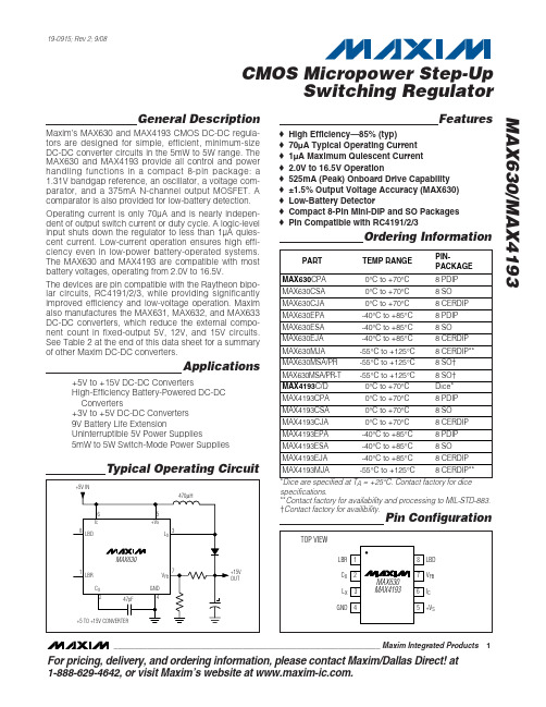
General DescriptionMaxim’s MAX630 and MAX4193 CMOS DC-DC regula-tors are designed for simple, efficient, minimum-size DC-DC converter circuits in the 5mW to 5W range. The MAX630 and MAX4193 provide all control and power handling functions in a compact 8-pin package: a 1.31V bandgap reference, an oscillator, a voltage com-parator, and a 375mA N-channel output MOSF ET. A comparator is also provided for low-battery detection.Operating current is only 70µA and is nearly indepen-dent of output switch current or duty cycle. A logic-level input shuts down the regulator to less than 1µA quies-cent current. Low-current operation ensures high effi-ciency even in low-power battery-operated systems.The MAX630 and MAX4193 are compatible with most battery voltages, operating from 2.0V to 16.5V.The devices are pin compatible with the Raytheon bipo-lar circuits, RC4191/2/3, while providing significantly improved efficiency and low-voltage operation. Maxim also manufactures the MAX631, MAX632, and MAX633DC-DC converters, which reduce the external compo-nent count in fixed-output 5V, 12V, and 15V circuits.See Table 2 at the end of this data sheet for a summary of other Maxim DC-DC converters.Applications+5V to +15V DC-DC ConvertersHigh-Efficiency Battery-Powered DC-DC Converters+3V to +5V DC-DC Converters 9V Battery Life ExtensionUninterruptible 5V Power Supplies5mW to 5W Switch-Mode Power SuppliesFeatures♦High Efficiency—85% (typ)♦70µA Typical Operating Current ♦1µA Maximum Quiescent Current ♦2.0V to 16.5V Operation♦525mA (Peak) Onboard Drive Capability ♦±1.5% Output Voltage Accuracy (MAX630)♦Low-Battery Detector♦Compact 8-Pin Mini-DIP and SO Packages ♦Pin Compatible with RC4191/2/3MAX630/MAX4193CMOS Micropower Step-UpSwitching Regulator________________________________________________________________Maxim Integrated Products 1Pin ConfigurationOrdering InformationTypical Operating Circuit19-0915; Rev 2; 9/08For pricing, delivery, and ordering information,please contact Maxim/Dallas Direct!at 1-888-629-4642, or visit Maxim’s website at .*Dice are specified at T A = +25°C. Contact factory for dice specifications.**Contact factory for availability and processing to MIL-STD-883.†Contact factory for availibility.M A X 630/M A X 4193CMOS Micropower Step-Up Switching Regulator 2_______________________________________________________________________________________ABSOLUTE MAXIMUM RATINGSELECTRICAL CHARACTERISTICSStresses beyond those listed under “Absolute Maximum Ratings” may cause permanent damage to the device. These are stress ratings only, and functional operation of the device at these or any other conditions beyond those indicated in the operational sections of the specifications is not implied. Exposure to absolute maximum rating conditions for extended periods may affect device reliability.Supply Voltage.......................................................................18V Storage Temperature Range ............................-65°C to +160°C Lead Temperature (soldering, 10s).................................+300°C Operating Temperature RangeMAX630C, MAX4193C........................................0°C to +70°C MAX630E, MAX4193E.....................................-40°C to +85°C MAX630M, MAX4193M..................................-55°C to +125°CPower Dissipation8-Pin PDIP (derate 6.25mW/°C above +50°C).............468mW 8-Pin SO (derate 5.88mW/°C above +50°C)................441mW 8-Pin CERDIP (derate 8.33mW/°C above +50°C)........833mW Input Voltage (Pins 1, 2, 6, 7).....................-0.3V to (+V S + 0.3V)Output Voltage, L X and LBD..................................................18V L X Output Current..................................................525mA (Peak)LBD Output Current............................................................50mAMAX630/MAX4193CMOS Micropower Step-UpSwitching Regulator_______________________________________________________________________________________3L X ON-RESISTANCE vs.TEMPERATURETEMPERATURE (°C)L X R O N (Ω)100755025-25-5024680125SUPPLY CURRENT vs.TEMPERATUREM A X 630/4193 t o c 02TEMPERATURE (°C)I S (μA )100755025-25-50402080601201001400125SUPPLY CURRENT vs.SUPPLY VOLTAGEM A X 630/4193 t o c 03+V S (V)I S (μA )14121086425015010025020030016Typical Operating Characteristics(T A = +25°C, unless otherwise noted.)ELECTRICAL CHARACTERISTICSNote 1:Guaranteed by correlation with DC pulse measurements.Note 2:The operating frequency range is guaranteed by design and verified with sample testing.Detailed DescriptionThe operation of the MAX630 can best be understood by examining the voltage regulating loop of F igure 1.R1 and R2 divide the output voltage, which is com-pared with the 1.3V internal reference by comparator COMP1. When the output voltage is lower than desired,the comparator output goes high and the oscillator out-put pulses are passed through the NOR gate latch,turning on the output N-channel MOSFET at pin 3, L X .As long as the output voltage is less than the desired voltage, pin 3 drives the inductor with a series of pulses at the oscillator frequency.Each time the output N-channel MOSFET is turned on,the current through the external coil, L1, increases,storing energy in the coil. Each time the output turns off,the voltage across the coil reverses sign and the volt-age at L X rises until the catch diode, D1, is forward biased, delivering power to the output.When the output voltage reaches the desired level,1.31V x (1 + R1 / R2), the comparator output goes low and the inductor is no longer pulsed. Current is then supplied by the filter capacitor, C1, until the output volt-age drops below the threshold, and once again L X is switched on, repeating the cycle. The average duty cycle at L X is directly proportional to the output current.Output Driver (L X Pin)The MAX630/MAX4193 output device is a large N-channel MOSFET with an on-resistance of 4Ωand a peak current rating of 525mA. One well-known advan-tage that MOSF ETs have over bipolar transistors in switching applications is higher speed, which reduces switching losses and allows the use of smaller, lighter,less costly magnetic components. Also important is that MOSF ETs, unlike bipolar transistors, do not require base current that, in low-power DC-DC converters,often accounts for a major portion of input power.The operating current of the MAX630 and MAX4193increases by approximately 1µA/kHz at maximum power output due to the charging current required by the gate capacitance of the L X output driver (e.g., 40µA increase at a 40kHz operating frequency). In compari-son, equivalent bipolar circuits typically drive their NPN L X output device with 2mA of base drive, causing the bipolar circuit’s operating current to increase by a fac-tor of 10 between no load and full load.OscillatorThe oscillator frequency is set by a single external, low-cost ceramic capacitor connected to pin 2, C X . 47pF sets the oscillator to 40kHz, a reasonable compromise between lower switching losses at low frequencies and reduced inductor size at higher frequencies.M A X 630/M A X 4193CMOS Micropower Step-Up Switching Regulator 4_______________________________________________________________________________________Low-Battery DetectorThe low-battery detector compares the voltage on LBR with the internal 1.31V reference. The output, LBD, is an open-drain N-channel MOSFET. In addition to detecting and warning of a low battery voltage, the comparator can also perform other voltage-monitoring operations such as power-failure detection.Another use of the low-battery detector is to lower the oscillator frequency when the input voltage goes below a specified level. Lowering the oscillator frequency increases the available output power, compensating for the decrease in available power caused by reduced input voltage (see Figure 5).Logic-Level Shutdown InputThe shutdown mode is entered whenever I C (pin 6) is driven below 0.2V or left floating. When shut down, theMAX630’s analog circuitry, oscillator, L X , and LBD out-puts are turned off. The device’s quiescent current dur-ing shutdown is typically 10nA (1µA max).Bootstrapped OperationIn most circuits, the preferred source of +V S voltage for the MAX630 and MAX4193 is the boosted output volt-age. This is often referred to as a “bootstrapped” oper-ation since the circuit figuratively “lifts” itself up.The on-resistance of the N-channel L X output decreas-es with an increase in +V S ; however, the device operat-ing current goes up with +V S (see the Typical Operating Characteristics , I S vs. +V S graph). In circuits with very low output current and input voltages greater than 3V, it may be more efficient to connect +V S direct-ly to the input voltage rather than bootstrap.MAX630/MAX4193CMOS Micropower Step-UpSwitching Regulator_______________________________________________________________________________________5Figure 1. +5V to +15V Converter and Block DiagramM A X 630/M A X 4193External ComponentsResistorsSince the LBR and V FB input bias currents are specified as 10nA (max), the current in the dividers R1/R2 and R3/R4 (Figure 1) may be as low as 1µA without signifi-cantly affecting accuracy. Normally R2 and R4 are between 10k Ωand 1M Ω, which sets the current in the voltage-dividers in the 1.3µA to 130µA range. R1 and R3 can then be calculated as follows:where V OUT is the desired output voltage and V LB isthe desired low-battery warning threshold.If the I C (shutdown) input is pulled up through a resistor rather than connected directly to +V S , the current through the pullup resistor should be a minimum of 4µAInductor ValueThe available output current from a DC-DC voltageboost converter is a function of the input voltage, exter-nal inductor value, output voltage, and the operating frequency.The inductor must 1) have the correct inductance, 2) be able to handle the required peak currents, and 3) have acceptable series resistance and core losses. If the inductance is too high, the MAX630 will not be able to deliver the desired output power, even with the L X out-put on for every oscillator cycle. The available output power can be increased by either decreasing the inductance or the frequency. Reducing the frequency increases the on-period of the L X output, thereby increasing the peak inductor current. The available out-put power is increased since it is proportional to the square of the peak inductor current (I PK ).where P OUT includes the power dissipated in the catchdiode (D1) as well as that in the load. If the inductance is too low, the current at L X may exceed the maximum rating. The minimum allowed inductor value is expressed by:where I MAX ≈525mA (peak L X current) and t ON is the on-time of the L X output.The most common MAX630 circuit is a boost-mode converter (Figure 1). When the N-channel output device is on, the current linearly rises since:At the end of the on-time (14µs for 40kHz, 55% duty-cycle oscillator) the current is:The energy in the coil is:At maximum load, this cycle is repeated 40,000 timesper second, and the power transferred through the coil is 40,000 x 5.25 = 210mW. Since the coil only supplies the voltage above the input voltage, at 15V, the DC-DC converter can supply 210mW / (15V - 5V) = 21mA. The coil provides 210mW and the battery directly supplies another 105mW, for a total of 315mW of output power. If the load draws less than 21mA, the MAX630 turns on its output only often enough to keep the output voltage at a constant 15V.Reducing the inductor value increases the available output current: lower L increases the peak current,thereby increasing the available power. The external inductor required by the MAX630 is readily obtained from a variety of suppliers (Table 1). Standard coils are suitable for most applications.Types of InductorsMolded InductorsThese are cylindrically wound coils that look similar to 1W resistors. They have the advantages of low cost and ease of handling, but have higher resistance, higher losses, and lower power handling capability than other types.102112131131104134131131ΩΩΩΩ≤≤=−≤≤=− .. ..R M R R x V VR M R R x V VOUTLBCMOS Micropower Step-Up Switching Regulator 6_______________________________________________________________________________________Potted Toroidal InductorsA typical 1mH, 0.82Ωpotted toroidal inductor (Dale TE-3Q4TA) is 0.685in in diameter by 0.385in high and mounts directly onto a PC board by its leads. Such devices offer high efficiency and mounting ease, but at a somewhat higher cost than molded inductors.Ferrite Cores (Pot Cores)Pot cores are very popular as switch-mode inductors since they offer high performance and ease of design.The coils are generally wound on a plastic bobbin,which is then placed between two pot core sections. A simple clip to hold the core sections together com-pletes the inductor. Smaller pot cores mount directly onto PC boards through the bobbin terminals. Cores come in a wide variety of sizes, often with the center posts ground down to provide an air gap. The gap pre-vents saturation while accurately defining the induc-tance per turn squared.Pot cores are suitable for all DC-DC converters, but are usually used in the higher power applications. They are also useful for experimentation since it is easy to wind coils onto the plastic bobbins.Toroidal CoresIn volume production, the toroidal core offers high per-formance, low size and weight, and low cost. They are,however, slightly more difficult for prototyping, in that manually winding turns onto a toroid is more tedious than on the plastic bobbins used with pot cores.Toroids are more efficient for a given size since the flux is more evenly distributed than in a pot core, where the effective core area differs between the post, side, top,and bottom.Since it is difficult to gap a toroid, manufacturers produce toroids using a mixture of ferromagnetic powder (typically iron or Mo-Permalloy powder) and a binder. The perme-ability is controlled by varying the amount of binder,which changes the effective gap between the ferromag-netic particles. Mo-Permalloy powder (MPP) cores have lower losses and are recommended for the highest effi-ciency, while iron powder cores are lower cost.DiodesIn most MAX630 circuits, the inductor current returns to zero before L X turns on for the next output pulse. This allows the use of slow turn-off diodes. On the other hand, the diode current abruptly goes from zero to full peak current each time L X switches off (Figure 1, D1).To avoid excessive losses, the diode must therefore have a fast turn-on time.F or low-power circuits with peak currents less than 100mA, signal diodes such as 1N4148s perform well.For higher-current circuits, or for maximum efficiency at low power, the 1N5817 series of Schottky diodes are recommended. Although 1N4001s and other general-purpose rectifiers are rated for high currents, they are unacceptable because their slow turn-on time results in excessive losses.MAX630/MAX4193CMOS Micropower Step-UpSwitching Regulator_______________________________________________________________________________________7Table 1. Coil and Core ManufacturersM A X 630/M A X 4193Filter CapacitorThe output-voltage ripple has two components, with approximately 90 degrees phase difference between them. One component is created by the change in the capacitor’s stored charge with each output pulse. The other ripple component is the product of the capacitor’s charge/discharge current and its effective series resis-tance (ESR). With low-cost aluminum electrolytic capacitors, the ESR-produced ripple is generally larger than that caused by the change in charge.where V IN is the coil input voltage, L is its inductance, f is the oscillator frequency, and ESR is the equivalent series resistance of the filter capacitor.The output ripple resulting from the change in charge on the filter capacitor is:where t CHG and t DIS are the charge and dischargetimes for the inductor (1/2f can be used for nominal cal-culations).Oscillator Capacitor, C XThe oscillator capacitor, C X , is a noncritical ceramic or silver mica capacitor. C X can also be calculated by:where f is the desired operating frequency in Hertz, and C INT is the sum of the stray capacitance on the C X pin and the internal capacitance of the package. The internal capacitance is typically 1pF for the plastic package and 3pF for the CERDIP package. Typical stray capacitances are about 3pF for normal PC board layouts, but will be significantly higher if a socket is used.Bypassing and CompensationSince the inductor-charging current can be relatively large, high currents can flow through the ground con-nection of the MAX630/MAX4193. To prevent unwanted feedback, the impedance of the ground path must be as low as possible, and supply bypassing should be used for the device.When large values (>50k Ω) are used for the voltage-setting resistors, R1 and R2 of F igure 1, stray capaci-tance at the V FB input can add a lag to the feedback response, destabilizing the regulator, increasing low-frequency ripple, and lowering efficiency. This can often be avoided by minimizing the stray capacitance at the V FB node. It can also be remedied by adding a lead compensation capacitor of 100pF to 10nF in paral-lel with R1 in Figure 1.DC-DC Converter ConfigurationsDC-DC converters come in three basic topologies:buck, boost, and buck-boost (Figure 2). The MAX630 is usually operated in the positive-voltage boost circuit,where the output voltage is greater than the input.The boost circuit is used where the input voltage is always less than the desired output and the buck circuit is used where the input is greater than the output. Thebuck-boost circuit inverts, and can be used with, inputCMOS Micropower Step-Up Switching Regulator 8_______________________________________________________________________________________Figure 2. DC-DC Converter Configurationsvoltages that are either greater or less than the output. DC-DC converters can also be classified by the control method. The two most common are pulse-width modu-lation (PWM) and pulse-frequency modulation (PF M). PWM switch-mode power-supply ICs (of which current-mode control is one variant) are well-established in high-power off-line switchers. Both PWM and PF M cir-cuits control the output voltage by varying duty cycle. In the PWM circuit, the frequency is held constant and the width of each pulse is varied. In the PFM circuit, the pulse width is held constant and duty cycle is con-trolled by changing the pulse repetition rate.The MAX630 refines the basic PFM by employing a con-stant-frequency oscillator. Its output MOSFET is switched on when the oscillator is high and the output voltages is lower than desired. If the output voltage is higher than desired, the MOSFET output is disabled for that oscillator cycle. This pulse skipping varies the average duty cycle, and thereby controls the output voltage.Note that, unlike the PWM ICs, which use an op amp as the control element, the MAX630 uses a comparator tocompare the output voltage to an onboard reference. This reduces the number of external components and operating current.Typical Applications+5V to +15V DC-DC Converter Figure 1 shows a simple circuit that generates +15V at approximately 20mA from a +5V input. The MAX630 has a ±1.5% reference accuracy, so the output voltage has an untrimmed accuracy of ±3.5% if R1 and R2 are 1% resistors. Other output voltages can also be select-ed by changing the feedback resistors. Capacitor C X sets the oscillator frequency (47pF = 40kHz), while C1 limits output ripple to about 50mV.With a low-cost molded inductor, the circuit’s efficiency is about 75%, but an inductor with lower series resis-tance such as the Dale TE3Q4TA increases efficiency to around 85%. A key to high efficiency is that the MAX630 itself is powered from the +15V output. This provides the onboard N-channel output device with 15V gate drive, lowering its on-resistance to about 4Ω. When +5V power is first applied, current flows through L1 and D1, supplying the MAX630 with 4.4V for startup.+5V to ±15V DC-DC Converter The circuit in F igure 3 is similar to that of F igure 1 except that two more windings are added to the induc-tor. The 1408 (14mm x 8mm) pot core specified is an IEC standard size available from many manufacturers (see Table 1). The -15V output is semiregulated, typi-cally varying from -13.6V to -14.4V as the +15V load current changes from no load to 20mA.2.5W, 3V to 5V DC-DC ConverterSome systems, although battery powered, need high currents for short periods, and then shut down to a low-power state. The extra circuitry of Figure 4 is designed tomeet these high-current needs. Operating in the buck-boost or flyback mode, the circuit converts -3V to +5V.The left side of Figure 4 is similar to Figure 1 and sup-plies 15V for the gate drive of the external power MOS-FET. This 15V gate drive ensures that the external deviceis completely turned on and has low on-resistance.The right side of F igure 4 is a -3V to +5V buck-boost converter. This circuit has the advantage that when theMAX630 is turned off, the output voltage falls to 0V,unlike the standard boost circuit, where the output volt-age is V BATT- 0.6V when the converter is shut down.When shut down, this circuit uses less than 10µA, withmost of the current being the leakage current of the power MOSFET.The inductor and output-filter capacitor values havebeen selected to accommodate the increased power levels. With the values indicated, this circuit can supplyup to 500mA at 5V, with 85% efficiency. Since the leftside of the circuit powers only the right-hand MAX630,the circuit starts up with battery voltages as low as1.5V, independent of the loading on the +5V output.MAX630/MAX4193CMOS Micropower Step-UpSwitching Regulator _______________________________________________________________________________________9M A X 630/M A X 4193+3V Battery to +5V DC-DC ConverterA common power-supply requirement involves conver-sion of a 2.4V or 3V battery voltage to a 5V logic sup-ply. The circuit in Figure 5 converts 3V to 5V at 40mA with 85% efficiency. When I C (pin 6) is driven low, the output voltage will be the battery voltage minus the drop across diode D1.The optional circuitry using C1, R3, and R4 lowers the oscillator frequency when the battery voltage falls to 2.0V. This lower frequency maintains the output-power capability of the circuit by increasing the peak inductor current, compensating for the reduced battery voltage.Uninterruptable +5V SupplyIn Figure 6, the MAX630 provides a continuous supply of regulated +5V, with automatic switchover between line power and battery backup. When the line-powered input voltage is at +5V, it provides 4.4V to the MAX630and trickle charges the battery. If the line-powered input falls below the battery voltage, the 3.6V battery supplies power to the MAX630, which boosts the bat-tery voltage up to +5V, thus maintaining a continuous supply to the uninterruptable +5V bus. Since the +5V output is always supplied through the MAX630, there are no power spikes or glitches during power transfer.The MAX630’s low-battery detector monitors the line-powered +5V, and the LBD output can be used to shut down unnecessary sections of the system during power failures. Alternatively, the low-battery detector could monitor the NiCad battery voltage and provide warning of power loss when the battery is nearly discharged.Unlike battery backup systems that use 9V batteries,this circuit does not need +12V or +15V to recharge the battery. Consequently, it can be used to provide +5V backup on modules or circuit cards that only have 5V available.9V Battery Life ExtenderFigure 7’s circuit provides a minimum of 7V until the 9V battery voltage falls to less than 2V. When the battery voltage is above 7V, the MAX630’s I C pin is low, putting it into the shutdown mode that draws only 10nA. When the battery voltage falls to 7V, the MAX8212 voltage detector’s output goes high, enabling the MAX630. The MAX630 then maintains the output voltage at 7V, even as the battery voltage falls below 7V. The LBD is used to decrease the oscillator frequency when the battery voltage falls to 3V, thereby increasing the output cur-rent capability of the circuit.CMOS Micropower Step-Up Switching Regulator 10______________________________________________________________________________________Figure 4. High-Power 3V to 5V Converter with ShutdownNote that this circuit (with or without the MAX8212) can be used to provide 5V from four alkaline cells. The initial volt-age is approximately 6V, and the output is maintained at 5V even when the battery voltage falls to less than 2V.Dual-Tracking RegulatorA MAX634 inverting regulator is combined with a MAX630 in F igure 8 to provide a dual-tracking ±15Voutput from a 9V battery. The reference for the -15V output is derived from the positive output through R3and R4. Both regulators are set to maximize output power at low-battery voltage by reducing the oscillator frequency, through LBR, when V BATT falls to 7.2V.MAX630/MAX4193Switching Regulator______________________________________________________________________________________11Figure 5. 3V to 5V Converter with Low-Battery Frequency ShiftFigure 7. Battery Life Extension Down to 3V InFigure 6. Uninterruptable +5V SupplyM A X 630/M A X 4193Switching Regulator 12______________________________________________________________________________________Table 2. Maxim DC-DC ConvertersFigure 8. ±12V Dual-Tracking RegulatorMAX630/MAX4193Switching Regulator______________________________________________________________________________________13Package InformationFor the latest package outline information, go to /packages .Chip TopographyLBR17I CV FB6230.089"(2.26mm)C XL XM A X 630/M A X 4193Switching Regulator Maxim cannot assume responsibility for use of any circuitry other than circuitry entirely embodied in a Maxim product. No circuit patent licenses are implied. Maxim reserves the right to change the circuitry and specifications without notice at any time.14____________________Maxim Integrated Products, 120 San Gabriel Drive, Sunnyvale, CA 94086 408-737-7600©2008 Maxim Integrated Productsis a registered trademark of Maxim Integrated Products, Inc.Revision History。
- 1、下载文档前请自行甄别文档内容的完整性,平台不提供额外的编辑、内容补充、找答案等附加服务。
- 2、"仅部分预览"的文档,不可在线预览部分如存在完整性等问题,可反馈申请退款(可完整预览的文档不适用该条件!)。
- 3、如文档侵犯您的权益,请联系客服反馈,我们会尽快为您处理(人工客服工作时间:9:00-18:30)。
General DescriptionThe MAX6305–MAX6313 CMOS microprocessor (µP)supervisory circuits are designed to monitor more than one power supply. Ideal for monitoring both 5V and 3.3V in personal computer systems, these devices assert a system reset if any of the monitored supplies falls outside the programmed threshold. Low supply current (15µA) and a small package suit them for portable applications. The MAX6305–MAX6313 are specifically designed to ignore fast transients on any monitored supply.These devices are available in a SOT23-5 package,have factory-programmed reset thresholds from 2.5V to 5.0V (in 100mV increments), and feature four power-on reset timeout periods. Ten standard versions are avail-able. Contact the factory for availability of non standard versions.ApplicationsPortable Computers Computers ControllersIntelligent InstrumentsPortable/Battery-Powered Equipment Multivoltage Systems: 3V/5V, 5V/12V, 5V/24V Embedded Control SystemsFeatureso Small 5-Pin SOT23 Packageo Precision Factory-Set V CC Reset Thresholds;Available in 0.1V Increments from 2.5V to 5V o Immune to Short V CC Transientso Guaranteed RESET Valid to V CC = 1V o Guaranteed Over Temperature o 8µA Supply Currento Factory-Set Reset Timeout Delay from 1ms (min) to 1120ms (min)o No External Components o Manual Reset Inputo Under/Overvoltage Supply MonitoringMAX6305–MAX63135-Pin, Multiple-Input,Programmable Reset ICs________________________________________________________________Maxim Integrated Products119-1145; Rev 5; 4/08†The MAX6306/MAX6307/MAX6309/MAX6310/MAX6312/MAX6313 are available with factory-set V CC reset thresholds from 2.5V to 5V, in 0.1V increments. Insert the desired nominal reset threshold (from Table 1) into the blanks following the letters UK.All parts also offer factory-programmed reset timeout periods.Insert the number corresponding to the desired nominal timeout period index following the “D” in the part number (D1 = 1ms min,D2 = 20ms min, D3 = 140ms min, and D4 = 1120ms min). There are 10 standard versions with a required order increment of 2,500pieces. Sample stock is generally held on the standard versions only (see Standard Versions table). Required order increment is 10,000 pieces for non-standard versions. Contact factory for availability of non-standard versions. All devices available in tape-and-reel only.Devices are available in both leaded and lead-free packaging.Specify lead-free by replacing “-T” with “+T” when ordering.Pin Configurations and Typical Operating Circuit appear atend of data sheet.Ordering Information continued at end of data sheet.Standard Versions Table appears at end of data sheet._______________________________________________________________Selector TableFor pricing, delivery, and ordering information, please contact Maxim Direct at 1-888-629-4642,or visit Maxim’s website at .M A X 6305–M A X 63135-Pin, Multiple-Input, Programmable Reset ICsABSOLUTE MAXIMUM RATINGSELECTRICAL CHARACTERISTICSV CC = +2.5V to +5.5V for the MAX6305/MAX6308/MAX6311, V CC = (V TH + 2.5%) to +5.5V for the MAX6306/MAX6307/MAX6309/Stresses beyond those listed under “Absolute Maximum Ratings” may cause permanent damage to the device. These are stress ratings only, and functional operation of the device at these or any other conditions beyond those indicated in the operational sections of the specifications is not implied. Exposure to absolute maximum rating conditions for extended periods may affect device reliability.V CC ...........................................................................-0.3V to +6V All Other Pins..............................................-0.3V to (V CC + 0.3V)Input/Output Current, All Pins.............................................20mA Rate of Rise, V CC ............................................................100V/µs Continuous Power Dissipation (T A = +70°C)SOT23-5 (derate 7.1mW/°C above +70°C).................571mWOperating Temperature RangeMAX63_ _UK _ _D_-T.........................................0°C to +70°C MAX63_ _EUK _ _D_-T...................................-40°C to +85°C Storage Temperature Range.............................-65°C to +160°C Lead Temperature (soldering, 10sec).............................+300°CMAX6305–MAX63135-Pin, Multiple-Input, Programmable Reset ICs_______________________________________________________________________________________3ELECTRICAL CHARACTERISTICS (continued)V CC = +2.5V to +5.5V for the MAX6305/MAX6308/MAX6311, V CC = (V TH + 2.5%) to +5.5V for the MAX6306/MAX6307/MAX6309/Note 2: The MAX6305/MAX6308/MAX6311 switch from undervoltage reset to normal operation between 1.5V < V CC < 2.5V.Note 3: The MAX6306/MAX6307/MAX6309/MAX6310/MAX6312/MAX6313 monitor V CC through an internal factory-trimmed voltagedivider, which programs the nominal reset threshold. Factory-trimmed reset thresholds are available in approximately 100mV increments from 2.5V to 5V (Table 1).Note 4:Guaranteed by design.M A X 6305–M A X 63135-Pin, Multiple-Input, Programmable Reset ICs 4_________________________________________________________________________________________________________________________________Typical Operating Characteristics(V CC = +5V, T A = +25°C, unless otherwise noted.)5.05.56.06.57.07.58.08.59.09.5-60-40-2020406080100SUPPLY CURRENT vs. TEMPERATURETEMPERATURE (°C)S U P P L Y C U R R E N T (μA )01020304050607080-60-40-2020406080100V CC FALLING PROPAGATION DELAYvs. TEMPERATURETEMPERATURE (°C)P R O P A G A T I O N D E L A Y (n s )010203040506070-60-40-20020406080100OVRST IN RISING PROPAGATION DELAY vs. TEMPERATURE (OVERVOLTAGE RESET INPUT)TEMPERATURE (°C)P R O P A G A T I O N D E L A Y (n s )020406080100120-60-40-2020406080100RST IN_ FALLING PROPAGATION DELAY vs. TEMPERATURETEMPERATURE (°C)R S T I N _ P R O P A G A T I O N D E L A Y (n s )104001200800MAXIMUM TRANSIENT DURATION vs.VCC RESET THRESHOLD OVERDRIVE10OVERDRIVE, V TH - V CC (mV)T R A N S I E N T D U R A T I O N (μs )100100010,0000.900.920.940.960.981.001.021.041.061.081.10-60-40-20020406080100RESET TIMEOUT vs. TEMPERATURE6305 T O C 05TEMPERATURE (°C)N O R M A L I Z E D R E S E T T I M E O U T0.9900.9920.9940.9960.9981.0001.0021.0041.0061.0081.010-60-40-2020406080100RESET THRESHOLD vs. TEMPERATURE6305 T O C 06TEMPERATURE (°C)N O R M A L I Z E D R E S E T T H R E S H O L D (V /V )104001200800MAXIMUM TRANSIENT DURATION vs.OVRST IN THRESHOLD OVERDRIVE10OVERDRIVE, V OVRST IN - V REF (mV)T R A N S I E N T D U R A T I O N (μs )100100010,000104001200800MAXIMUM TRANSIENT DURATION vs.RST IN_ THRESHOLD OVERDRIVE10OVERDRIVE, V REF - V RST IN (mV)T R A N S I E N T D U R A T I O N (μs )100100010,000_______________Detailed DescriptionThe MAX6305–MAX6313 CMOS microprocessor (µP)supervisory circuits are designed to monitor more than one power supply and issue a system reset when any monitored supply falls out of regulation. The MAX6305/MAX6308/MAX6311 have two adjustable undervoltage reset inputs (RST IN1 and RST IN2). The MAX6306/MAX6307/MAX6309/MAX6310/MAX6312/MAX6313 mon-itor V CC through an internal, factory-trimmed voltage divider. The MAX6306/MAX6309/MAX6312 have, in addition, an adjustable undervoltage reset input and a manual-reset input. The internal voltage divider sets the reset threshold as specified in the device part number (Table 1). The MAX6307/MAX6310/ MAX6313 feature an adjustable undervoltage reset input (RST IN) and an adjustable overvoltage reset input (OVRST IN) in addition to the factory-trimmed reset threshold on the V CC moni-tor. Program the adjustable reset inputs with an external resistor divider (see Adjustable Reset Inputs section).Reset OutputsA µP’s reset input starts the µP in a known state. These µP supervisory circuits assert reset to prevent code-execution errors during power-up, power-down, or brownout conditions.RESET (MAX6305–MAX6310) and RESET (MAX6311/MAX6312/MAX6313) are guaranteed to be asserted at a valid logic level for V CC > 1V (see Electrical Characteristics ). Once all monitored voltages exceed their programmed reset thresholds, an internal timer keeps reset asserted for the reset timeout period (t RP );after this interval, reset deasserts.If a brownout condition occurs (any or all monitored volt-ages dip outside their programmed reset threshold),reset asserts (RESET goes high; RESET goes low). Any time any of the monitored voltages dip below their reset threshold, the internal timer resets to zero and reset asserts. The internal timer starts when all of the moni-tored voltages return above their reset thresholds, and reset remains asserted for a reset timeout period. The MAX6305/MAX6306/MAX6307 feature an active-low,MAX6305–MAX63135-Pin, Multiple-Input, Programmable Reset ICs_______________________________________________________________________________________5______________________________________________________________Pin DescriptionM A X 6305–M A X 6313open-drain, N-channel output. The MAX6308/MAX6309/MAX6310 feature an active-low, complementary output structure that both sinks and sources current, and the MAX6311/MAX6312/MAX6313 have an active-high com-plementary reset output.The MAX6305/MAX6308/MAX6311 switch from under-voltage lockout operation to normal operation between 1.5V < V CC < 2.5V. Below 1.5V, V CC undervoltage-lockout mode asserts RESET . Above 2.5V, V CC normal-operation mode asserts reset if RST IN_ falls below the RST IN_ threshold.Manual-Reset Input(MAX6306/MAX6309/MAX6312)Many µP-based products require manual-reset capability,allowing an operator or external logic circuitry to initiate a reset. A logic low on MR asserts reset. Reset remains asserted while MR is low, and for a reset active timeout period (t RP ) after MR returns high. This input has an inter-nal 63.5k Ωpull-up resistor, so it can be left open if it is not used. MR can be driven with TTL-logic levels in 5V sys-tems, with CMOS-logic levels in 3V systems, or with open-drain/collector output devices. Connect a normally open momentary switch from MR to GND to create a manual-reset function; external debounce circuitry is not required.If MR is driven from long cables or if the device is used in a noisy environment, connecting a 0.1µF capacitor from MR to ground provides additional noise immunity.The MR pin has internal ESD-protection circuitry that may be forward biased under certain conditions, drawing excessive current. For example, assume the circuitry driv-ing MR uses a +5V supply other than V CC . If V CC drops or browns out lower than +4.7V, MR ’s absolute maximum rat-ing is violated (-0.3V to (V CC + 0.3V)), and undesirable current flows through the ESD structure from MR to V CC .To avoid this, it is recommended that the supply for the MR pin be the same as the supply monitored by V CC . In this way, the voltage at MR will not exceed V CC .Adjustable Reset InputsThe MAX6305–MAX6313 each have one or more reset inputs (RST IN_ /OVRST IN). These inputs are com-pared to the internal reference voltage (F igure 1).Connect a resistor voltage divider to RST IN_ such that V RST IN_falls below V RSTH (1.23V) when the monitored voltage (V IN ) falls below the desired reset threshold (V TH ) (F igure 2). Calculate the desired reset voltage with the following formula:R1 + R2V TH = ________x VRSTHR25-Pin, Multiple-Input, Programmable Reset ICs 6_______________________________________________________________________________________Figure 1. Functional DiagramMAX6305–MAX63135-Pin, Multiple-Input, Programmable Reset ICs_______________________________________________________________________________________7The ±25nA max input leakage current allows resistors on the order of megohms. Choose the pull-up resistor in the divider to minimize the error due to the input leakage cur-rent. The error term in the calculated threshold is simply:±25nA x R1If you choose R1 to be 1M Ω, the resulting error is ±25 x 10-9x 1 x 106= ±25mV.Like the V CC voltage monitors on the MAX6306/MAX6307/MAX6309/MAX6310/MAX6312/MAX6313, the RST IN_inputs (when used with a voltage divider) are designed to ignore fast voltage transients. Increase the noise immunity by connecting a capacitor on the order of 0.1µF between RST IN and GND (Figure 2). This creates a single-pole lowpass filter with a corner frequency given by:f = (1/2π) / (R1 + R2)(R1 x R2 x C)For example, if R1 = 1M Ωand R2 = 1.6M Ω, adding a 0.1µF capacitor from RST IN_ to ground results in a lowpass corner frequency of f = 2.59Hz. Note that adding capacitance to RST IN slows the circuit’s overall response time.__________Applications InformationInterfacing to µPs with Bidirectional Reset PinsSince the RESET output on the MAX6305/MAX6306/MAX6307 is open drain, these devices interface easily with µPs that have bidirectional reset pins, such as the Motorola 68HC11. Connecting the µP supervisor’s RESET output directly to the microcontroller’s RESET pin with a single pull-up resistor allows either device to assert reset (Figure 3).Negative-Going V CC TransientsIn addition to issuing a reset to the µP during power-up,power-down, and brownout conditions, these devices are relatively immune to short-duration, negative-going V CC transients (glitches).The Typical Operating Characteristics show the Maximum Transient Duration vs. V CC Reset Threshold Overdrive, for which reset pulses are not generated.The graph was produced using negative-going pulses,starting at V TH max, and ending below the pro-grammed reset threshold by the magnitude indicated (reset threshold overdrive). The graph shows the maxi-mum pulse width that a negative-going V CC transient may typically have without causing a reset pulse to be issued. As the amplitude of the transient increases (i.e.,goes farther below the reset threshold), the maximum allowable pulse width decreases.RST IN_/OVRST IN are also immune to negative/positive-going transients (see Typical Operating Characteristics ).A 0.1µF bypass capacitor mounted close to the RST IN_,OVRST IN, and/or the V CC pin provides additional tran-sient immunity.Ensuring a Valid RESET /RESETOutput Down to V CC = 0VWhen V CC falls below 1V, push/pull structured RESET /RESET current sinking (or sourcing) capabilities decrease drastically. High-impedance CMOS-logic inputs connected to RESET can drift to undetermined voltages. This presents no problem in most applica-tions, since most µPs and other circuitry do not operate with V CC below 1V. In those applications where RESET must be valid down to 0V, adding a pull-down resistor between RESET and ground sinks any stray leakageFigure 2. Increasing Noise ImmunityFigure 3. Interfacing to µPs with Bidirectional Reset I/Ocurrents, holding RESET low (Figure 4). The pull-down resistor’s value is not critical; 100k Ωis large enough not to load RESET and small enough to pull RESET to ground. For applications where RESET must be valid to V CC , a 100k Ωpull-up resistor between RESET and V CC will hold RESET high when V CC falls below 1V (Figure 5).Since the MAX6305/MAX6306/MAX6307 have open-drain, active-low outputs, they typically use a pull-up resistor. With these devices and under these conditions (V CC < 1V), RESET will most likely not maintain an active condition, but will drift toward a nonactive level due to the pull-up resistor and the RESET output’s reduction in sinking capability. These devices are not recommended for applications that require a valid RESET output below 1V.* Factory-trimmed reset thresholds are available in approximately 100mV increments with a ±1.5% room-temperature variance.M A X 6305–M A X 63135-Pin, Multiple-Input, Programmable Reset ICs 8_______________________________________________________________________________________Figure 4. Ensuring RESET Valid to V CC = 0VFigure 5. Ensuring RESET Valid to V CC = 0VTable 1. Factory-Trimmed Reset Thresholds*MAX6305–MAX63135-Pin, Multiple-Input, Programmable Reset ICs_______________________________________________________________________________________9Chip InformationTRANSISTOR COUNT: 800Typical Operating Circuit†The MAX6306/MAX6307/MAX6309/MAX6310/MAX6312/MAX6313 are available with factory-set V CC reset thresholds from 2.5V to 5V, in 0.1V increments. Insert the desired nominal reset threshold (from Table 1) into the blanks following the letters UK.All parts also offer factory-programmed reset timeout periods.Insert the number corresponding to the desired nominal timeout period index following the “D” in the part number (D1 = 1ms min,D2 = 20ms min, D3 = 140ms min, and D4 = 1120ms min). There are 10 standard versions with a required order increment of 2,500pieces. Sample stock is generally held on the standard versions only (see Standard Versions table). Required order increment is 10,000 pieces for non-standard versions. Contact factory for avail-ability of non-standard versions. All devices available in tape-and-reel only.Devices are available in both leaded and lead-free packaging.Specify lead-free by replacing “-T” with “+T” when ordering.M A X 6305–M A X 63135-Pin, Multiple-Input, Programmable Reset ICs 10______________________________________________________________________________________Pin ConfigurationsPackage InformationFor the latest package outline information, go to /packages .Maxim cannot assume responsibility for use of any circuitry other than circuitry entirely embodied in a Maxim product. No circuit patent licenses are implied. Maxim reserves the right to change the circuitry and specifications without notice at any time.Maxim Integrated Products, 120 San Gabriel Drive, Sunnyvale, CA 94086 408-737-7600 ____________________11©2008 Maxim Integrated Productsis a registered trademark of Maxim Integrated Products, Inc.MAX6305–MAX6313 5-Pin, Multiple-Input, Programmable Reset ICs元器件交易网。