美国OMEGA校准入门手册
OMEGA用户手册 (11)
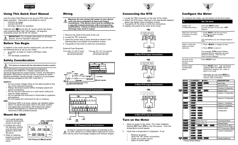
Using This Quick Start ManualUse this Quick Start Manual to set up your RTD meter and begin operation. Information is provided on how to:•Connect ac power •Connect the RTD •Set basic options for operationcharacters shown are for the “B” version.Before You BeginIn addition to the meter and the related parts, you will need the following items to set up your meter:•ac power, as listed on meter’s ID/Power Label •RTD •1/8” flat blade screwdriverSafety Considerationaccordance with EN61010-1 (Safety requirements forelectrical equipment for measurement, control, and laboratory standard). Remember that the unit has no power-on switch.Building installation should include a switch or circuit-breaker that must be compliant to IEC 947-1 and 947-3.SAFETY:•Do not exceed voltage rating on the label located on the top of the instrument housing.•Always disconnect power before changing signal and power connections.•Do not use this instrument on a work bench without its case for safety reasons.•Do not operate this instrument in flammable or explosive atmospheres.•Do not expose this instrument to rain or moisture.EMC:•Whenever EMC is an issue, always use shielded cables. •Never run signal and power wires in the same conduit.•Use signal wire connections with twisted-pair cables.•Install Ferrite Bead(s) on signal wire close to the instrument if EMC problems persist.Mount the Unit1.Cut a panel opening using the dimensions shown to the right.2.Position the unit in the opening, making sure the front bezel gasket is flush with the panel.3.Slide on retaining bracket to secure the meter against the panel.23456DP25B-RTD and DP25-RTDProgrammable Digital RTD MeterMQS3733/0206It is the policy of OMEGA to comply with all worldwide safety and EMC/EMI regulations that apply. OMEGA is constantly pursuing certification of its products to the European New Approach Directives. OMEGA will add the CE mark to every appropriate device upon certification.The information contained in this document is believed to be correct but OMEGA Engineering, Inc. accepts no liability for any errors it contains, and reserves the right to alter specifications without notice.TRADEMARK NOTICE:® ®, and,are trademarks of OMEGA WARNING:These products are not designed for use in, and should not be used for, patient connected applications.Engineering, Inc.。
Omega CL542 温度传感器校准仪说明书

e-mail:**************For latest product manuals:User’s GuideCL542Thermocouple CalibratorJ, T, E, K, R, S, B, N, mV®Shop online atregulations that apply. OMEGA is constantly pursuing certification of its products to the European New Approach Directives. OMEGA will add the CE mark to every appropriate device upon certification.The information contained in this document is believed to be correct, but OMEGA accepts no liability for any errors it contains, and reserves the right to alter specifications without notice.WARNING: These products are not designed for use in, and should not be used for, human applications.1Basic Keypad Operations1EZ-Check™ SwitchSOURCE mode: Slide the switch to select from three user-storedvalues for the desired calibration points. The user can select HI, DIAL and LO positions. These values can easily be changed to suit the calibration requirements.READ mode: Slide the switch to recall minimum and maximum readings. Press the EZ-Dial™ Knob to clear the stored values.2SOURCE/OFF/READ SwitchSlide the SOURCE/OFF/READ Switch to SOURCE to output a voltage corresponding to the temperature on the display for the selected thermocouple type. Use the READ position todirectly convert thermocouple input to temperature.3EZ-Dial™ KnobTurn the knob to change temperature in 0.1ºincrements. Push and turn for faster dialing.Push without turning to store new EZ-Check™ HI/LO points in SIMULATE mode, or to clear EZ-Check™ HI/LO points in READ mode.CL542 ConfigurationInstructions for Enabling and Disabling the Configuration Options1.Turn the CL542 on with the SOURCE/OFF/READ Switch.2.Press the EZ-Dial™ Knob while the “PRESS EZ-DIAL KNOB FOR CONFIGURATION”message is displayed.3.Select options by turning the EZ-Dial™ Knob until the arrow points to the desired option.4.The option can be enabled or disabled by tapping the EZ-Dial™ Knob.The CL542 configuration menu will exit automatically after 5 seconds of inactivity and goto normal operation with the options selected. These options are saved even when the unit is turned off.CL542 ConfigurationDouble-click the EZ-Dial™ Knob while in source or READ mode to enter the configuration menu.Hold the EZ-Dial™ Knob while turning the unit on to bypass the “PRESS EZ-DIAL KNOB FOR CONFIGURATION”message altogether. CL542 Configuration MenuAuto Off ON/OFFIf Auto Off is ON,the unit will turn off after30 minutes to save battery life, if there is no user activity. If Auto Off is OFF the unit will stay on until it is turned off from the keypad. This is typically useful for manual loading or continuous use.Display Units °C/°FPressing the EZ-Dial™ Knob to toggles between °C or °FS,T,or mVT/C B,E,J,K,N,R,To change T/C type, press the EZ-Dial™ Knob. Turn the EZ-Dial™ Knob to scroll through the list of available types.Press again to save and return to the configuration menu.READ ModeSlide the SOURCE/OFF/READ Switch to READ for direct thermocouple input. The CL542 displays temperature correspondingto input for the selected thermocouple type.Connect the T/C sensor. “OPEN T/C” will be displayed until properly connected.Slide the EZ-Check™ Switch to HI and LO to recall maximum and minimum saved readings. Press and hold the EZ-Dial™ Knob to clear saved readings. The display flashes “CLEARED” as a confirmation.Double-click the EZ-Dial™ Knob to return to the configuration menu.Turning the EZ-Dial™ Knob has no effect in READ mode.Other Display Indications:OVERRANGE or UNDERRANGE The millivoltage input exceeds the selected thermocouple type’s range.OPEN T/C No thermocouple is connected, or the connected thermocouple exhibits> 10 kΩ.SOURCE ModeSlide the SOURCE/OFF/READ Switch to SOURCE for direct thermocouple output. The CL542 outputs voltage corresponding to temperature for the selected thermocouple type.Slide the EZ-Check Switch to HI or LO to recall stored settings. While in the HI or LO position, dial a new setting and press theEZ-Dial™ Knob to store. The DIAL position always holds the last setting dialed there.Turn the EZ-Dial™ Knob to change temperature, push and turn for faster dialing.Double-click the EZ-Dial™ Knob to return to the configuration menu.23Connection DiagramTwo Wire Connection to TransmitterSpecificationsGeneral Specifications:Unless otherwise indicated all specifications are rated from a nominal 23 °C, 70 % RH for 1 year from calibration.READ Thermocouple Specifications:Temperature AccuracyThe following charts give worst-case temperature accuracy based on stated millivolt accuracy of ±(0.008 % + 0.006). Temperature is uncompensated on the horizontal axis, referenced to 0 °C. Cold Junction calibration accuracy of 0.1 °C is not included in the temperature error.TYPE B594 to 1820 °C0 00TYPE E-260 to 1000 °C00TYPE J-210 to 1200 °C00TYPE K-245 to 1372 °C0 0000TYPE N-229 to 1300 °C00TYPE R24 to1768 °C00TYPE S21 to 1768 °C0000TYPE T-251to 400 °C004CL542 Field Calibration Procedure1.Precision Voltage Meter with an accuracy of 0.0039% at 80.000mV.2.Precision Voltage Source with an accuracy of 0.0039% at 80.000mV.3.Precision Thermistor probe with accuracy of ± 0.025°C or better (YSI 46046)OR4. A stable ice bath or Thermocouple ice point calibrator and a NIST traceablethermocouple wire stable to within ±0.025°C.Omega recommends using a direct junction temperature measurement technique for the most accurate and reliable calibrations of our equipment. This technique uses accurate RTD or thermistor probes to measure the reference junction (cold junction) temperature. While measuring the junction voltage with a DVM and ice bath technique will work. This method is less reliable due to complexity and is generally less accurate due to cumulative errors.Avoid touching thermocouple connections, as this will cause temperature errors in calibration. It is recommended that the CL542 be handled as little as possible during calibration to reduce errors.The heat from your body may cause uneven heating of temperature sensitive components.Place in a fresh battery and allow 15 minutes for the CL542 to stabilize to the ambient temperature. Remove the EZ-Dial™ Knob, battery cover and the four black Phillips head screws. While holding the CL542 face down in one hand, carefully separate the top and bottom of the housing. Place the units into calibration mode by shorting the calibration via located on the bottom right side of the PCB with tweezers and turn the UUT on. Verify the CL542 is in calibrationmode by viewing the bottom of the LCD for the word “CAL”.Connect the Model 522 terminals to a Voltage Meter.left side of the LCD.2.Dial the CL542 so the meter reads 0.000 mV.3.Press the EZ-Dial™ Knob down.4.The display will flash “STORED” to confirm that the value was stored.left side of the LCD.2.Dial the CL542 so the meter reads 80.000 mV.3.Press the EZ-Dial™ Knob down.4.The display will flash “STORED” to confirm that the value was stored.Double click the EZ-Dial™ Knob to enter the Cold Junction Calibration Mode. “Cal CJ” will appear on the top left of the LCD.52.Connect the other side of the thermistor probe to the OHM meter.3.Let the temperature settle for 15minutes.4.Check the Cold Junction Temperature on the top right of the LCD with the temperaturereading of the thermistor probe.5.If the reading is out of specification then dial the EZ-Dial™ to the temperature readingfrom the thermistor probe.6.Press the EZ-Dial™ Knob down.7.The display will flash “STORED” to confirm that the value was stored.8.Verify the UUT (top right side of the LCD) Cold Junction Temperature is tracking withthe temperature reading of the thermistor probe.2.Let the temperature settle for 15 minutes.3.Check the Cold Junction Temperature on the top right of the LCD to the voltage readingon the DVM and T/C chart.4.If the reading is out of Specification then dial the EZ-Dial™ to the correct reading fromthe DVM and T/C chart.5.Press the EZ-Dial™ Knob down.6.The display will flash “STORED” to confirm that the value was stored.7.Verify the UUT (top right side of the LCD) Cold Junction Temperature is tracking withthe temperature reading of the DVM and T/C TableConnect the CL542 terminals to a DC Voltage Source.side of the LCD.2.Set the voltage source to 0.000 mV.3.Press the EZ-Dial™ Knob down4.The display will flash “STORED” to confirm that the value was stored.6side of the LCD.2.Set the voltage source to 80.000 mV.3.Press the EZ-Dial™ Knob down4.The display will flash “STORED” to confirm that the value was stored.Turn the CL542 OFF. Next time the unit is turned on the CL542 will be calibrated and innormal operational mode.7NOTES 8Direct all warranty and repair requests/inquiries to the OMEGA Customer Service Department. BEFORE RET URNING ANY PRODUCT(S) T O OMEGA, PURCHASER MUST OBT AIN AN AUT HORIZED RET URN (AR) NUMBER FROM OMEGA’S CUST OMER SERVICE DEPART MENT (IN ORDER T O AVOID PROCESSING DELAYS). T he assigned AR number should then be marked on the outside of the return package and on any correspondence.The purchaser is responsible for shipping charges, freight, insurance and proper packaging to prevent breakage in transit.FOR WARRANTY RETURNS, please have the following information available BEFORE contacting OMEGA:1.Purchase Order number under whichthe product was PURCHASED,2.Model and serial number of the productunder warranty, and3.Repair instructions and/or specificproblems relative to the product.FOR NON-WARRANTY REPAIRS,consult OMEGA for current repair charges. Have the following information available BEFORE contacting OMEGA:1. Purchase Order number to cover theCOST of the repair,2.Model and serial number of theproduct, and3.Repair instructions and/or specific problemsrelative to the product.OMEGA’s policy is to make running changes, not model changes, whenever an improvement is possible. This affords our customers the latest in technology and engineering.OMEGA is a registered trademark of OMEGA ENGINEERING, INC.© Copyright 2005 OMEGA ENGINEERING, INC. All rights reserved. This document may not be copied, photocopied, reproduced, translated, or reduced to any electronic medium or machine-readable form, in whole or in part, without the prior written consent of OMEGA ENGINEERING, INC.Where Do I Find Everything I Need for Process Measurement and Control?OMEGA…Of Course!Shop online at TEMPERATUREⅪߜThermocouple, RTD & Thermistor Probes, Connectors, Panels & AssembliesⅪߜWire: Thermocouple, RTD & ThermistorⅪߜCalibrators & Ice Point ReferencesⅪߜRecorders, Controllers & Process MonitorsⅪߜInfrared PyrometersPRESSURE, STRAIN AND FORCEⅪߜTransducers & Strain GagesⅪߜLoad Cells & Pressure GagesⅪߜDisplacement TransducersⅪߜInstrumentation & AccessoriesFLOW/LEVELⅪߜRotameters, Gas Mass Flowmeters & Flow ComputersⅪߜAir Velocity IndicatorsⅪߜTurbine/Paddlewheel SystemsⅪߜTotalizers & Batch ControllerspH/CONDUCTIVITYⅪߜpH Electrodes, Testers & AccessoriesⅪߜBenchtop/Laboratory MetersⅪߜControllers, Calibrators, Simulators & PumpsⅪߜIndustrial pH & Conductivity EquipmentDATA ACQUISITIONⅪߜData Acquisition & Engineering SoftwareⅪߜCommunications-Based Acquisition SystemsⅪߜPlug-in Cards for Apple, IBM & CompatiblesⅪߜDatalogging SystemsⅪߜRecorders, Printers & PlottersHEATERSⅪߜHeating CableⅪߜCartridge & Strip HeatersⅪߜImmersion & Band HeatersⅪߜFlexible HeatersⅪߜLaboratory HeatersENVIRONMENTALMONITORING AND CONTROLⅪߜMetering & Control InstrumentationⅪߜRefractometersⅪߜPumps & TubingⅪߜAir, Soil & Water MonitorsⅪߜIndustrial Water & Wastewater TreatmentⅪߜpH, Conductivity & Dissolved Oxygen Instruments M4206/0605。
Omega CL514-PLUS 自动 universal RTD 校准仪说明书
e-mail:**************For latest product manuals:User’s GuideCL514-PLUSAutomatedUniversal RTD Calibrator®Shop online atIt is the policy of OMEGA Engineering, Inc. to comply with all worldwide safety and EMC/EMI regulations that apply. OMEGA is constantly pursuing certification of its products to the European New Approach Directives. OMEGA will add the CE mark to every appropriate device upon certification.The information contained in this document is believed to be correct, but OMEGA accepts no liability for any errors it contains, and reserves the right to alter specifications without notice.WARNING: These products are not designed for use in, and should not be used for, human applications.Page 1• Easy to useWith the CL514-PLUS you can check & calibrate all your RTD instruments and measure RTD Sensors. Automatic indication of connections on the display for simple hookups.• Take it without into the shop, plant or field Carry it without worry - it comes protected with a rubber boot and rugged, low profile switch. Easy to operate even in the dark areas of the plant with the backlit display.• Calibrate directly in temperature (°C & °F)Stop carrying around a decade box and RTDresistance tables. The CL514-PLUS works with the RTDs you use including Platinm 100 (alpha = 3850, 3902, 3926) & 1000 (alpha = 3850, 3750) Ohm, Copper 10 & 50 Ohm, Nickel 100 and 120 Ohm. Easily set any value quickly to within 0.1° with the adjustable digital potentiometer “DIAL ” plus store any three temperatures for instant recall with the OMEGA switch.• Calibrate quickly with automatic output stepping Choose between 2, 3, 5, 11 and 21 steps toautomatically increment the output in 100%, 50%, 25%, 10% or 5% of span. Select the step time to match your system from 5, 6, 7, 8, 10, 15, 20, 25, 30 and 60 seconds.• Compatible with all process instruments Connect directly to the RTD inputs of smarttransmitters, PLCs, DCS and multichannel recorders and verify their outputs or displays. Works with older instruments with fixed excitation currents and newer multichannel instruments that switch the excitation current between input channels.• Measure RTD SensorsTrouble shoot sensor connections and find broken wires with patented technology. Connect your two, three or four wire RTDs and the CL514-PLUS automatically detects the connections and measures the RTD in degrees C or F.Page 2OMEGA SWITCHSOURCE: Instantly output two preset RTD temperatures by moving the OMEGA switch to the “LO” position or “HI” position. For fast three point checks select the “DIAL ” position. The CL514-PLUS will remember the last “DIAL ” value, even with the power off.These values can easily be changed to suit the calibration requirements. The temperatures stored in the HI and LO positions are also used for Auto Stepping.READ: Slide the switch to the DIAL position. The CL514-PLUS will display the current temperature from the RTD sensor. Slide the switch to HI and the highest temperature measured since turn-on or reset will be displayed; slide the switch to LO and the lowest temperature measured since turn-on or reset will be displayed.2 SOURCE/OFF/READ SwitchSelect “SOURCE ” to output in °C, °F or ohms. Select “READ ” to read an RTD sensor or ohms.3 PUSH-BUTTON KNOBSOURCE: Turn the knob to adjust the outputlevel. Turn clockwise to increase the output, °1.0 n i t u p t u o e h t e s a e r c e d o t e s i w k c o l c r e t n u o c steps at a time. Push down and turn the PUSH-BUTTON knob for faster dialing.Press and hold the knob for two seconds to store desired OMEGA HI/LO points in SIMULATE mode. Continue to press and hold the knob for two more seconds to start the automatic ramping.READ: Press and hold to transfer the current temperature into the OMEGA HI/LO points. This clears the HI/LO temperature readings which will update as the temperature changes.Double click the knob to get into the CL514-PLUS Configuration Mode. Use configuration to select °C or °F , T/C Type, Backlight On/Off, Step Size, Step Time and Auto Off On/Off.CHANGING BATTERIESLow battery is indicated by “BAT” on the display. Approximately one to four hours of typical operation remain before the CL514-PLUS will automatically turn off. T o change the batteries; remove the rubber boot, remove the battery door from the back of the unit by sliding the door downward. This allows access to the battery compartment. Replace with four (4) “AA ” 1.5V batteries being careful to check the polarity. Replace the battery door and replace the boot. All stored configuration options (RTD Type, OMEGA Memories, etc., are reset to factory settings when the batteries are removed.Note: Alkaline batteries are supplied and recommended for maximum battery life and performance.values to factory defaults.Turn the 3 PUSH-BUTTON knob to movethrough the menu. Press the 3 PUSH-BUTTONknob to toggle between OFF and ON or to scrollthrough the settings.Page 3Page 4SOURCEChoose this function to provide a simulated RTD signal into controllers, temperature transmitters, indicators or any input devices that measure thermocouple sensors.1)Disconnect the RTDsensor fromthe devicebe calibrated.2) Select “SOURCE ” with slide switch 2.3) 3 or 4 wires matching the connections of sensor that was just removed.The output is adjusted in 0.1° (or 0.01/0.1 increments by turning the knob 3 while OMEGA switch 1 with 10° (or 1.00/10.0 ohm) increments.The OVERLOAD indicator will light if voltage or current is detected by the calibrator.READChoose this function to measure temperatures with an RTD probe or sensor.1) Disconnect the RTD sensor from any other device.2) Select “READ ” with slide switch 2.3) Place the OMEGA switch into the READ position.4) Connect the CL514-PLUS to the device using 2, 3 or 4 wires.The CL514-PLUS measures the temperature signal and constantly updates the display with the current temperature reading. Move the OMEGA switch to MAX to see the highest temperature reading and to MIN to see the lowest temperature reading. Press and hold the knob 3 to clear the MAX and MIN readings.The OVERLOAD indicator will light if excessive voltage or current is detected by the calibrator.Page 5To change the Automatic Stepping settingsDouble click the 3 PUSH-BUTTON knob at any time the unit is on and the following display will appear for 30 seconds:Turn the 3 PUSH-BUTTON knob to move through the menu. Press the 3 PUSH-BUTTON knob to toggle between OFFand ON or to change the STEPS and the STEP TIME settings.These settings are remembered even with the power off. EXIT MENU - exits this menu immediately and saves anychanges. Menu will automatically exit after 30 seconds of inactivity.STEPS - pressing the knob will cycle through 2, 3, 5, 11 and 21 steps then reverse dircetion. The endpoints of the steps are based on the values stored in the HI and LO EZ-CHECK outputs. 2 steps will automatically switch between the values stored in the HI & LO OMEGA (0 & 100%).3 steps between the HI, Midpoint and LO OMEGA (0, 50 & 100%).5 steps between the HI and LO OMEGA in 25% increments (0, 25, 50, 75 & 100%).11 steps between the HI and LO OMEGA in 10% increments (0, 10, 20...80, 90 &100%).21 steps between the HI and LO OMEGA in 5% increments (0, 5, 10... 90, 95 & 100%).STEP TIME - pressing the knob will cycle through 5, 6, 7, 8, 9, 10, 15, 20, 25, 30 and 60 seconds. To start the Automatic SteppingStart automatic stepping or ramping by placing the OMEGA Switch into the HI or LO position then press and hold the 3 PUSH-BUTTON knob for 6 seconds (the word STORE will appear on the display after 3 seconds and continue to press the PUSH-BUTTON knob) until the wordSTEPPING appears on the display. The word STEPPING will appear on the display anytime the selected automatic function is running. Stop the stepping by again pressing and holding the 3 PUSH-BUTTON knob for 3 seconds.STORING HI and LO OMEGA OutputsChoose this function to provide a simulated thermocouple signal into controllers, temperature transmitters, indicators or any other input device that measure thermocouple sensors..1) Store your high (SPAN) output temperature by moving the OMEGA switch to the HI position and turn the 3 PUSH-BUTTON knob until the desired temperature is on the display. Press and hold the knob until STORED appears to store the value. Release the PUSH-BUTTON knob.2) Store your low (ZERO) output temperature by moving the OMEGA switch to the LO position and turn the 3 PUSH-BUTTON knob until the desired temperature is on the display. Press and hold the PUSH-BUTTON knob until STORED appears to store the value. Release the PUSH-BUTTON knob. 3) Instantly output your SPAN and ZERO temperature outputs by moving the OMEGA switch between HI and LO. Y ou may also select any third temperature output (such as mid-range) using the SET position on the OMEGA switch.EXIT 15> STEPS 3 STEP TIME 8 AUTO OFF ONPage 6(Unless otherwise indicated all specifications are rated from a nominal 23°C,70% RH for 1 year from calibration)Page 7This product is calibrated on equipment traceable to NIST and includes a Certificate of Calibration. Test Data is available for an additional charge.Included:Rubber Boot, Four “AA” Alkaline batteries, Certificate of CalibrationLarge Carrying Case Part No. SC-530 Omega RTD Wire Kit2 Red & 2 Black Leads with Retractable Shield Banana Plugs & Spade LugsPage 8WARRANTY/DISCLAIMEROMEGA ENGINEERING, INC. warrants this unit to be free of defects in materials and workmanship for a period of 37 months from date of purchase. OMEGA’s WARRANTY adds an additional one (1) month grace period to the normal three (3) year product warranty to cover handling and shipping time. This ensures that OMEGA’s customers receive maximum coverage on each product.If the unit malfunctions, it must be returned to the factory for evaluation. OMEGA’s Customer Service Department will issue an Authorized Return (AR) number immediately upon phone or written request. U pon examination by OMEGA, if the unit is found to be defective, it will be repaired or replaced at no charge. OMEGA’s WARRANTY does not apply to defects resulting from any action of the purchaser, including but not limited to mishandling, improper interfacing, operation outside of design limits, improper repair, or unauthorized modification.This WARRANTY is VOID if the unit shows evidence of having been tampered with or shows evidence of having been damaged as a result of excessive corrosion; or current, heat, moisture or vibration; improper specification; misapplication; misuse or other operating conditions outside of OMEGA’s control. Components in which wear is not warranted, include but are not limited to contact points, fuses, and triacs.OMEGA is pleased to offer suggestions on the use of its various products. However, OMEGA neither assumes responsibility for any omissions or errors nor assumes liability for any damages that result from the use of its products in accordance with information provided by OMEGA, either verbal or written. OMEGA warrants only that the parts manufactured by the company will be as specified and free of defects. OMEGA MAKES NO OTHER WARRANTIES OR REPRESENTATIONS OF ANY KIND W HATSOEVER, EXPRESSED OR IMPLIED, EXCEPT THAT OF TITLE, AND ALL IMPLIED W ARRANTIES INCLUDING ANY W ARRANTY OF MERCHANTABILITY AND FITNESS FOR A PARTICULAR PURPOSE ARE HEREBY DISCLAIMED. LIMITATION OF LIABILITY: The remedies of purchaser set forth herein are exclusive, and the total liability of OMEGA with respect to this order, whether based on contract, warranty,negligence, indemnification, strict liability or otherwise, shall not exceed the purchase price of the component upon which liability is based. In no event shall OMEGA be liable for consequential, incidental or special damages.CONDITIONS: Equipment sold by OMEGA is not intended to be used, nor shall it be used: (1)as a “Basic Component” under 10 CFR 21 (NRC), used in or with any nuclear installation or activity; or (2) in medical applications or used on humans. Should any Product(s) be used in or with any nuclear installation or activity, medical application, used on humans, or misused in any way, OMEGA assumes no responsibility as set forth in our basic WARRANTY/ DISCLAIMER language, and, additionally, purchaser will indemnify OMEGA and hold OMEGA harmless from any liability or damage whatsoever arising out of the use of the Product(s) in such a manner.RETURN REQUESTS/INQUIRIESDirect all warranty and repair requests/inquiries to the OMEGA Customer Service Department.BEFORE RETU RNING ANY PRODU CT(S) TO OMEGA, PU RCHASER MU ST OBTAIN AN AU THORIZED RETU RN (AR) NU MBER FROM OMEGA’S CU STOMER SERVICE DEPARTMENT (IN ORDER TO AVOID PROCESSING DELAYS). The assigned AR number should then be marked on the outside of the return package and on any correspondence.The purchaser is responsible for shipping charges, freight, insurance and proper packaging to prevent breakage in transit.FOR WARRANTY RETURNS, please havethe following information available BEFOREcontacting OMEGA:1.Purchase Order number under whichthe product was PURCHASED,2.Model and serial number of the productunder warranty, and3.Repair instructions and/or specificproblems relative to the product.FOR NON-WARRANTY REPAIRS,consult OMEGA for current repair charges. Have the following information available BEFORE contacting OMEGA:1. Purchase Order number to cover the COST of the repair,2.Model and serial number of theproduct, and 3.Repair instructions and/or specific problemsrelative to the product.OMEGA’s policy is to make running changes, not model changes, whenever an improvement is possible. This affords our customers the latest in technology and engineering.OMEGA is a registered trademark of OMEGA ENGINEERING, INC.© Copyright 2010 OMEGA ENGINEERING, INC. All rights reserved. This document may not be copied, photocopied,reproduced, translated, or reduced to any electronic medium or machine-readable form, in whole or in part, withoutthe prior written consent of OMEGA ENGINEERING, INC.Where Do I Find Everything I Need for Process Measurement and Control?OMEGA…Of Course!Shop online at SMTEMPERATUREⅪߜThermocouple, RTD & Thermistor Probes, Connectors, Panels & AssembliesⅪߜWire: Thermocouple, RTD & ThermistorⅪߜCalibrators & Ice Point ReferencesⅪߜRecorders, Controllers & Process MonitorsⅪߜInfrared PyrometersPRESSURE, STRAIN AND FORCEⅪߜTransducers & Strain GagesⅪߜLoad Cells & Pressure GagesⅪߜDisplacement TransducersⅪߜInstrumentation & AccessoriesFLOW/LEVELⅪߜRotameters, Gas Mass Flowmeters & Flow ComputersⅪߜAir Velocity IndicatorsⅪߜTurbine/Paddlewheel SystemsⅪߜTotalizers & Batch ControllerspH/CONDUCTIVITYⅪߜpH Electrodes, Testers & AccessoriesⅪߜBenchtop/Laboratory MetersⅪߜControllers, Calibrators, Simulators & PumpsⅪߜIndustrial pH & Conductivity EquipmentDATA ACQUISITIONⅪߜData Acquisition & Engineering SoftwareⅪߜCommunications-Based Acquisition SystemsⅪߜPlug-in Cards for Apple, IBM & CompatiblesⅪߜData Logging SystemsⅪߜRecorders, Printers & PlottersHEATERSⅪߜHeating CableⅪߜCartridge & Strip HeatersⅪߜImmersion & Band HeatersⅪߜFlexible HeatersⅪߜLaboratory HeatersENVIRONMENTALMONITORING AND CONTROLⅪߜMetering & Control InstrumentationⅪߜRefractometersⅪߜPumps & TubingⅪߜAir, Soil & Water MonitorsⅪߜIndustrial Water & Wastewater TreatmentⅪߜpH, Conductivity & Dissolved Oxygen Instruments M4839/0710。
OMEGA 完整测量和控制手册集说明书
Call for Your FREE Handbook Set Today: (203) 359-RUSHServicing USA and Canada: Call OMEGA Toll FreeOMEGA Engineering, Inc.One Omega Drive, Box 4047 Stamford, CT 06907-0047 U.S.A. Headquarters: (203) 359-1660Sales: 1-800-826-6342 / 1-800-TC-OMEGACustomer Service: 1-800-622-2378 / 1-800-622-BEST Engineering: 1-800-872-9436 / 1-800-USA--WHENFAX: (203) 359--7700 TELEX: 996404 EASYLINK:62968934 CABLE: OMEGAServicing Europe: United Kingdom Sales and Distribution CenterOMEGA Technologies Ltd.P.O. Box 1, Broughton Astley, LeicestershireLE9 6XR, EnglandTelephone: (0455) 285520 FAX: (0455) 283912The OMEGA Complete Measurement and Control Handbooks & Encyclopedias TMa Temperature a pH and Conductivitya Pressure, Strain & Force a Data Acquisition systems a Flow and Level aElectric HeatersPX831 and PX832REV AOperator’s ManualM3807/0502Electronic Pressure TransmittersWARRANTYOMEGA warrants this unit to be free of defects in materials and workmanship and to give satisfactory service for a period of 13 months (PX831) or 13 months (PX832) from date of purchase. OMEGA Warranty adds an additional one (1) month grace period to the normal product warranty to cover handling and shipping time. This ensures that our customers receive maximum coverage on each product. If the unit should malfunction, it must be returned to the factory for evaluation. Our Customer Service Department will issue an Authorized Return (AR) number immediately upon phone or written request. Upon examination by OMEGA, if the unit is found to be defective it will be repaired or replaced at no charge. However, this WARRANTY is VOID if the unit shows evidence of having been tampered with or shows evidence of being damaged as a result of excessive corrosion; or current, heat, moisture or vibration; improper specification; misapplication; misuse or other operating conditions outside of OMEGA's control. Components which wear or which are damaged by misuse are not warranted. These include contact points, fuses, and triacs.We are glad to offer suggestions on the use of our various products. Nevertheless OMEGA only warrants that the parts manufactured by it will be as specified and free of defects.OMEGA MAKES NO OTHER WARRANTIES OR REPRESENTATIONS OF ANY KIND WHATSOEVER, EXPRESSED OR IMPLIED, EXCEPT THAT OF TITLE AND ALL IMPLIED WARRANTIES INCLUDING ANY WARRANTY OF MERCHANTABILITY AND FITNESS FOR A PARTICULAR PURPOSE ARE HEREBY DISCLAIMED.LIMITATION OF LIABILITY: The remedies of buyer set forth herein are exclusive and the total liability of OMEGA with respect to this order, whether based on contract, warranty, negligence, indemnification, strict liability or otherwise, shall not exceed the purchase price of the component upon which liability is based. In no event shall OMEGA be liable for consequential, incidental or special damages.Every precaution for accuracy has been taken in the preparation of this manual, however, OMEGA ENGINEERING, INC. neither assumes responsibility for any omissions or errors that may appear nor assumes liability for any damages that result from the use of the products in accordance with the information contained in the manual.RETURN REQUESTS / INQUIRIESDirect all warranty and repair requests/inquiries to the OMEGA ENGINEERING Customer Service Department. Call toll free in the USA and-Canada: 1-800-622-2378, FAX: 203-359-781 1; International: 203359-1660, FAX: 203-359-7807.BEFORE RETURNING ANY PRODUCT(S) TO OMEGA, YOU MUST OBTAIN AN AUTHORIZED RETURN (AR) NUMBER. FROM OUR CUSTOMER SERVICE DEPARTMENT (IN ORDER TO AVOID PROCESSING DELAYS). The assigned AR number should then be marked on the outside of the return package and on any correspondence. FOR WARRANTY RETURNS, please have the following FOR NON-WARRANTY REPAIRS OR CALIBRATION information available BEFORE contacting OMEGA: consult OMEGA for current repair/calibrationcharges. Have the following information avail-1. P.O. number under which the product able BEFORE contacting OMEGA:was PURCHASED, 1. Your P.O. number to cover the COST2. Model and serial number of the product of the repair/calibration,under warranty, and 2. Model and serial number of product,3. Repair instructions and/or specific problems 3. Repair instructions and/or specific problemsyou are having with the product. you are having with the product.OMEGA's policy is to make running changes, not model changes, whenever an improvement is possible. That way our customers get the latest in technology and engineering.OMEGA is a registered trademark of OMEGA ENGINEERING, INC.(D Copyright 1992 OMEGA ENGINEERING, INC. All rights reserved including illustrations. Nothing in this manual may be reproduced in any manner, either wholly or in part for any purpose whatsoever without written permission from OMEGA ENGINEERING, INC. Printed in U.S.A.SECTION IIIOPERATIONPRINCIPLE OF OPERATIONThe Model PX831 and PX832 PressureTransmitter series are designed to continuouslymeasure process pressure. The heart of thetransmitter is a silicon piezoresistive sensing chip.This miniature microetched semiconductor givesan output proportional to the applied pressure.This chip is isolated from the process media by astainless steel diaphragm. A silicone oil or otherspecified fill fluid is used to transmit the processpressure to the sensor.A surface mount amplifier board, enclosed in asealed chamber, is used to convert the millivoltsignal from the sensor to a calibrated transmitteroutput. Transmitter electronics are completelysurge protected.Each transmitter is tested over both pressure andtemperature ranges. A thick film compensatorcircuit is used to bring the output of the sensorinto specification. After compensation, everytransmitter is tested a second time for pressure andtemperature effects to ensure that it meetsperformance specifications.3-1OPERATION2-2CONTENTSWARRANTY .............................................................................................................coverINTRODUCTION ...........................................................................................................ii SAFETY SUMMARY .. (ii)SECTION I - SPECIFICATIONSMODEL PX831 TRANSMITTER MODEL NUMBER CODE ..................................1-1 MODEL PX832 TRANSMITTER MODEL NUMBER CODE ..................................1-2 DESCRIPTION .........................................................................................................1-3 SPECIFICATIONS ....................................................................................................1-3 FUNCTIONAL .....................................................................................................1-3 PERFORMANCE .................................................................................................1-3 PHYSICAL ...........................................................................................................1-3 HAZARDOUS LOCATION CLASSIFICATION (FM) & (CSA) .............................1-3 OUTLINE DIMENSIONS .........................................................................................1-4SECTION II - INSTALLATIONMODEL PX831 and PX832 PIPING ........................................................................2-1 WIRING ....................................................................................................................2-2SECTION III - OPERATIONPRINCIPLE OF OPERATION ..................................................................................3-1iINTRODUCTION INTRODUCTIONThe Model PX831 and PX832 pressure transmitters provide fixed range performance and all 316 stainless steel construction in a durable, accurate and cost effective package. The transmitters provide 4-20 mA or Voltage output, ±0.30% accuracy and are designed to meet FM & CSA approvals for explosion proof apparatus for use in hazardous locations.Model PX831 and PX832 provid as standard a 1/2" NPT female process connection for direct mounting to existing piping systems. They are provided with a 3/4" NPT female conduit connection and a 24-inch, 22AWG, cable.SAFETY SUMMARYThese instruments are designed to prevent an accidental shock to the operator when properly used. However, no design can ensure the safety of an instrument improperly installed or used negligently. Read this manual carefully and completely before operating the instrument. Failure to read this manual in its entirety could result in damage to the instrument or injury to the operator. Standard safety precautions must be used during installation and operation. Important messages located throughout this manual are as follows:WARNING - Denotes a hazardous procedure or condition which, if ignored, couldresult in injury or death to the operator.CAUTION - Denotes a hazardous procedure or condition which, if ignored, couldresult in damage or destruction to the instrument.IMPORTANT - Denotes a procedure or condition that is essential to the correctoperation of the instrument.NOTE - Specifies supplementary and perhaps essential information inrelation to a particular procedure or condition.iiFIGURE 2-1MODEL PX831 and PX832 PIPINGSECTION II SPECIFICATIONS MODEL PX831 and PX832 PIPINGTransmitter mounting is shown in Figure 1A and 1B ofFigure 2-1, below.Conduit drain should be provided to prevent moisturebuildup in the conduit compartment.Figure 1C shows a transmitter mounting with an elbow toprevent sediment in the process from clogging the line.Figure 1D shows a transmitter mounting with an elbow toeliminate trapped vapor.2-1FIGURE 1-1OUTLINE DIMENSIONS (MODEL PX831 and PX832) SECTION I SPECIFICATIONS1-4 SCECTION I SPECIFICATIONS MODEL PX831 TRANSMITTER MODEL NUMBER CODEPX831 ELECTRONIC PRESSURE TRANSMITTERPRESSURE RANGEPSI BAROUTPUTI = 4-20 mADCMATERIALBASE DIAPHRAGM FILL PROCESS CONN.316L SS 316L SS SILICONE 1/2”NPT FEMALE PX831 100G I EXAMPLEModel PX831 Pressure Transmitter, 0 to 100 psig range, 316L SS base and diaphragm, silicone oil fill, 1/2” female NPT, output at 4-20 mADC,approved by FM an CSA.1-1015G 0-15 psig 0-1.0 bar030G 0-30 psig 0-2.0 bar100G 0-100 psig 0-7.0 bar300G 0-300 psig 0-20 bar1KG 0-1000 psig 0-70 bar3KG 0-3000 psig 0-200 bar5KG 0-5000 psig 0-350 bar30VAC 0-30 in HG Vacuum 0 to -1.0 bar30V15G 30 in HG Vac to 15 psig -1.0 to 1.0 bar30V30G 30 in HG Vac to 30 psig -1.0 to 2.0 bar30V60G 30 in Hg Vac to 60 psig -1.0 to 4.0 bar015A 0-15 psia 0-1.0 bar absolute030A 0-30 psia 0-2.0 bar absolute100A 0-100 psia 0– 7.0 bar absoluteSCECTION I SPECIFICATIONSMODEL PX832 TRANSMITTER MODEL NUMBER CODEPX832 ELECTRONIC PRESSURE TRANSMITTERPRESSURE RANGEPSI BAROUTPUT5V = 1-5 VDC MATERIALBASE DIAPHRAGM FILL PROCESS CONN. 316 SS 316L SS SILICONE 1/2”NPT FEMALEPX832 100G 5V EXAMPLEModel PX832 Pressure Transmitter, 0 to 100 psig range, 316L SS base and diaphragm, silicone oil fill, 1/2” female NPT, output at 1-5 VDC,approved by FM an CSA.015G 0-15 psig 0-1.0 bar 030G 0-30 psig 0-2.0 bar 100G 0-100 psig 0-7.0 bar 300G 0-300 psig 0-20 bar 1KG 0-1000 psig 0-70 bar 3KG 0-3000 psig 0-200 bar 5KG 0-5000 psig 0-350 bar1-2SECTION IDESCRIPTIONThe Model PX831 and PX832 are the most durable and cost effective pressure transmitters presentlyavailable. Fixed range, all stainless steel transmitters, are designed to continuously measure process pressure for years with stable performance in even the toughest environmental and media conditions. The silicon piezoresistive sensing element consists of four ion implanted strain gauges forming a Wheatstone bridge circuit which will vary its resistance when subjected to process pressure. The Model PX831 and PX832 meet FM & CSA approval for explosion-proof rating in hazardous locations. They also meet NACE standards for offshore applications.The small size and light weight of these transmitters eliminates the need for complicated mountinghardware and mechanical supports, thereby reducing installation time substantially. The inline connection permits simple field wiring without the need for additional hardware, adding to the speed and ease of installation. Its profile allows for mounting in places too tight for other transmitters.With all 316 stainless steel welded construction, the Model PX831 and PX832 are compatible with corrosive media and hazardous environments. The transmitters are weather proof and capable of withstanding direct spray.SPECIFICATIONSFUNCTIONAL SPECIFICATIONS Service: Liquid, Gas or Vapor Pressure Range Limits:-14.7 to 5000 PSI (-1.0 to 345 BAR) Input (Power Supply) / Output:PX831 = 12-30 VDC / 4-20 mADC, *Limited to 30 mADC PX832 = 8-14 VDC / 1-5 VDC OffsetPX831 = 4.0 mA ±2% Span PX832 = 1.0 VDC ±2% Span SpanPX831 = 16.0 mA ±l % Span PX832 = 4.0 VDC ±1% SpanLoop Resistance: 900 ohms max @ 30 VDC (PX831Only)Temperature RANGE:Ambient Operating: -400F to 1400F (-400C to 600C) Process Interface: -400F to 2120F (-400C to 1000C) Storage: –400F to 2120F (-400C to 1000C) Overpressure: 300% Span Humidity Limits: 0-100%RHPERFORMANCE SPECIFICATIONSAccuracy: ±0.30% of Span (BFSL) including linearity, Hysteresis and repeatability at 250C and 12 VDC supply voltageStability: ±0.50 Span for six monthsTemperature Effect: (includes zero & span) Compensated: -20 to 1400F (-29 to 600C) ±2.0% / 500F (280C)Vibration Effect: ±0.1% for 3g to 200 HzPHYSICAL SPECIFICATONS Materials of ConstructionProcess Wetted Parts: 316L SS Non Wetted Parts: 316 SS Fill Fluid: Silicone (DC200)Process Connection: 1/2" NPT-FemaleElectrical Connection: 3/4" NPT-Female / Cable Weight 0.83 lb. (374 grams)Cable: 24 inches (61 cm), 22 AWGCLASSIFICATIONS Factory MutualExplosion-proof for Class I, Division 1, Groups B, C & D Class II Groups E, F & G; and Class III Hazardous Locations and Indoor and Outdoor NEMA Type 4 Enclosure.Canadian Standards AssociationExplosion-proof for Class I, Division 1, Groups B, C & D, Class II, E, F & G and Class III Hazardous Locations and meets CSA requirements for Enclosure 4.SPECIFICATIONS1-3。
OMEGA PCL431 手持电流校准器说明书

PCL431Current CalibratorOperator’s ManualM1889/0994GENERAL DESCRIPTIONThe OMEGA®PCL431 Hand-Held Current Calibrator is designed to be a complete 4-20mA loop calibrator delivering high accuracy in a small, easy to use package. Its microprocessor based circuitry gives the usera large number of input/output options and operating modes without unnecessary complexity.Current can be sourced into loads up to 1000 ohms or simulated with external power supplies of up to60VDC. When operated in the read mode the user can input a current from a signal source directly, or in the read/power mode the PCL431 will supply 24 volt loop power to a two wire device and simultaneously monitor the resultant loop current. Both read and source measurements can be displayed directly inmilliamps or as a percentage of a 4-20mA loop.Commonly used outputs (up to 3) can be stored in the PCL431’s non-volatile memory for quick recall. In addition, an auto-step mode allows the calibrator to step through the selected setpoints at a user defined dwell time of 5 to 60 seconds.INSTALLATIONUNPACKINGRemove the Packing List and verify that all equipment has been received. If you have any questions about the shipment, please call the OMEGA Customer Service Department at 1-800-622-2378 or (203) 359-1660.When you receive the shipment, inspect the container and equipment for any signs of damage. Note any evidence of rough handling in transit. Immediately report any damage to the shipping agent.NOTE:The carrier will not honor any claims unless all shipping material is saved for theirexamination. After examining and removing contents, save packing material and carton in theevent reshipment is necessary.Check to see if your calibrator kit is complete - it should include:1. Carrying case (Qty=1)2. T est leads (Qty=1 set)3. 9V battery (Installed)4. Operator’s Manual (Qty=1)SET-UPBefore beginning, become familiar with the keypad layout and the configuration of the input/output jacks.Remember, these jacks are used in multiple configurations so pay careful attention to how the test leads are connected for the specific application.CJS0994RAF2BAOPERATING PROCEDURE1. Turn on power and select the desired range by depressing the ”RANGE SELECT” key.NOTE: When operating in the “%” range, 4mA=0% and 20mA=100%.2. Connections are made as follows:Current Source - Use jacks 1 and 2 (1 is +).Current Simulate - Use jacks 2 and 3 (2 is +).Current Read - Use jacks 3 and 4 (4 is +).Current Read/Power - Use jacks 1 and 4 (1 is +).3. The and keys adjust the output value up or down. Holding the ramp keys continuously forseveral seconds will increase the scroll rate. Going beyond the endpoints (0 and 24mA) will cause theoutput to wrap around, thus allowing a quick return to either end of the scale.4. Three calibration points can be stored in non-volatile memory by scrolling to the desired output,depressing the Store key, and then the desired setpoint key.5. The auto step will automatically step through the stored setpoints at pre-defined intervals. When theauto-step key is first depressed, the display will indicate the dwell time (in seconds) between steps.The factory set value is 15 seconds but you can set this value, from 5 to 60 seconds, by usingthe and keys when the dwell time is being displayed. Once you have scrolled to the desireddwell time, release the or key and wait approximately 3 seconds until the calibrator begins toautomatically step through the 3 setpoints. The calibrator will continue the stepping process until anykey is pressed. Your chosen dwell time will remain in a non-volatile memory location until you chooseto change it.OPERATING CONSIDERATIONS AND PRECAUTIONS1. When operating in the current source mode, the PCL431 has the capability to drive loads up to 1000ohms as shown in Figure 1.Figure 1 - Current Source Mode2. When operating in the current simulate mode, the PCL431 acts like a two-wire transmitter controlling acurrent loop with an external voltage of up to 60 VDC as shown in Figure 2.Figure 2 - Current Simulate Mode3. When reading a current loop, the PCL431 can measure over a range of 0-24mA. Connections areshown in Figure 3.Figure 3 - Current Loop Readings4. The PCL431 can simultaneously power a device with 24 volts and display the current flowing throughthe loop. This is particularly useful when calibrating a two-wire transmitter. A typical application isshown in Figure 4.Figure 4 - PCL431 Simultaneous Power/DisplayACCURACYThe PCL431 is checked against an NIST traceable reference before shipment to verify that each range falls within the 0.05%, ±1 count, of full scale accuracy specification. Long term accuracy should remain within0.1%, ±1 count, of FSR. All of these ratings are based on a 25°C ambient temperature. A change of 10°Cwill cause approximately a 1000 ppm change (based on 100 ppm/C temp.) in the output or the equivalent of a 0.1% output change. Therefore, allowances must be made for error caused by wide temperaturevariations.。
OMEGA CL561多功能校准仪说明书
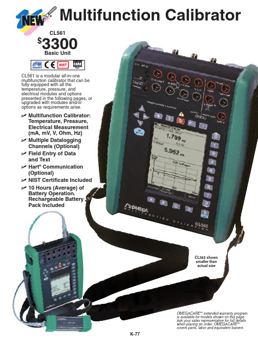
Multifunction Calibrator$Basic UnitCL561 is a modular all-in-onemultifunction calibrator that can be fully equipped with all the temperature, pressure, and electrical modules and optionspresented in the following pages, or upgraded with modules and/or options as requirements arise.CL562 shown smaller than actual sizeߜMultifunction Calibrator: Temperature, Pressure,Electrical Measurement (mA, mV, V, Ohm, Hz)ߜMultiple Datalogging Channels (Optional)ߜField Entry of Data and TextߜHart ®Communication (Optional)ߜNIST Certificate Included ߜ10 Hours (Average) of Battery Operation.Rechargeable BatteryPack IncludedOMEGACARE SM extended warranty program is available for models shown on this page.Ask your sales representative for full details when placing an order. OMEGACARE SM covers parts, labor and equivalent loanersPRESSURE MODULES (INT & EXT) (Optional, ordered with base unit or field installable)CL561 can have up to three (3) internal pressure modules. All the internal pressure modules, up to INT6C,are equipped with relief valves as overpressure protection. This together with the possibility to also use external pressure modules, gives CL561 a unique pressure calibration capability.A unit fitted with the barometric module allows all other pressure modules to also measure absolute pressure. The pressure modules incorporate advanced pressure measurement technology, whichmeans that only a few modules are needed to cover a very wide pressure range with excellent uncertainty.CL561 supports more than 30 different pressure units as standard.Electrical Module (Included With All Models)The electrical module (E), which is galvanically isolated from all the other modules, measures electrical quantities including frequency. Additionally it counts pulses and detects the state of switches (opening and closing values). It includes a +24V DC loop supply and also generates current.The E module hosts the optional Hart ®modem which allows digital communications with instruments which support the Hart ®protocol. CL561 automatically includes an internal modem plus 250 Ohm resistor needed for Hart ®communication when the +24V DC loop supply is used.for mentioned period. (k=2)2) Bias current <10 nA 3) Impedance >1 Mohm 4) Impedance < 7.5 ohm5) Impedance > 1 Mohm. Frequency measurement minimum amplitude 0.5 Vpp (< 5 kHz), 1 Vpp (5 to 50 kHz).Pulse counting minimum amplitude 0.5 Vpp (pulse length > 100 µs), 1 Vpp (pulse length 100 µs to 10 µs), Trigger level range -1 to +15 V.6) Maximum load impedance 800 ohmE Module FeaturesߜVoltage Measurement ߜPulse CountingߜLow Voltage Measurement ߜFrequency Measurement ߜCurrent Measurement ߜSwitch TestingߜCurrent Generation ߜ+24V DC Loop SupplyߜHosts the Hart ®Communication (Optional)Multifunction Calibrator (cont’d)Internal (INT) & External (EXT) Pressure Modulesfor mentioned period. (k=2)2)Every internal/external pressure module’s range may be displayed also in absolute pressure if the Barometric Module (B) is installed. Supports the following pressure units as standard: Pa, hPa, kPa, MPa, mbar, bar, lbf/ft 2, psi, gf/cm2, kgf/cm2, kgf/m2, kp/cm2,at, mm H2O, cm H2O, m H2O, iwc, ft H2O, mm Hg, cm Hg, m Hg, in Hg, mm Hg(0°C), in Hg(0°C), mm H2O (4°C), in H2O (4°C), ft H2O (4°C), in H2O (60°F), mm H2O (68°F), in H2O (68°F), ft H2O (68°F), torr, atm.Pressure modules 20bar and below, pressure connection G 1/8 (ISO 228/1) 60°internal cone.INT60, INT100, INT160 module pressure connection G 1/8 (ISO 228/1) female.EXT60, EXT100, EXT160, EXT250, EXT600, EXT1000 pressure module pressure connection G 1/4 (ISO 228/1) male.Wetted parts AISI316 stainless steel, Hastelloy, Nitrile rubber.In the INT20C, EXT20C, INT60, EXT60, INT100, EXT100, INT160, EXT160 and EXT250 themaximum overpressure is twice the range.The maximum overpressure for EXT600 is 900 bar and for EXT1000 1100 bar.module (see chart above)Additional RTD Types Included• Pt50 (385)• Pt400 (385)• Pt100 (3923)• Pt100 (391)• Ni100 (618)• Pt100 (385)• Pt500 (385)• Pt100 (389)• Pt100 (375)• Ni120 (672)• Pt200 (385)• Pt1000 (385)• Pt100 (3926)• Cu10 (427)RTD/ohm simulation excitation current 0.2 … 5 mA (1 … 1000 ohm), 0.1 … 1 mA (1 ... 4 kohm).TEMPERATURE ELECTRICAL MODULE (ET)(Included with the CL562)With the temperature and electrical module (ET) you can simulate and measure a great variety of RTD’s and thermocouples. Additionally you can generate electrical signals including frequency and pulses as well as measure and generate / simulate mV and ohm signals with the same module.Both the ITS90 and IPTS68 International Temperature Scales are selectable from the configuration menu in the CL562.The ET module hosts the reference junction (RJ) module. The RJ module operates using advanced temperature measurement technology providing very accurate internal cold junctioncompensation when measuring or simulating thermocouples.The unique design of the RJ module makes it possible to use practically any connector type or plain TC wires.ET Module FeaturesߜRTD Measurement/Simulation ߜFrequency Generation ߜResistance Measurement/SimulationߜPulse GenerationߜThermocouple Measurement/SimulationߜVoltage GenerationߜLow Voltage Measurement/GenerationߜCurrent GenerationߜHosts the Optional InternalReference Junction Module (RJ)2)Load effect < 5 µV/mA. Maximum output current 5 mA.3)Load effect < 100 µV/mA. Maximum output current 10 mA (0 .. 10 V), 3 mA (10 .. 12 V).4)Maximum load impedance 400 ohm.5)Amplitude range 0 .. 12 Vpp. Amplitude setting accuracy up to 5 kHz ±(200 mV + 5% of set value). Waveforms: Square wave (positive /symmetric) and sinewave (above 40 Hz).6)Pulse generation frequency range 0.1 ... 1000 Hz. Amplitude setting 0 ... 12 Vpp.7)Valid with measurement current 0.2 ... 5 mA (1 ... 1000 ohm), 0.1 .. 1mA (1 ... 4 kohm). Ohm/RTD simulation speed 1 ms.8)Which ever is greater.9)Specification valid with 4 wire connection. In 3 wire connection add 10 mohm.10)Bias current < 10 nA.Multifunction Calibrator (cont’d)Resolution 0.01°C.With internal reference junction (module RJ)add 0.1°C uncertainty.Thermocouple types C3(ASTM E 988 - 96), G3 (ASTM E 1751 - 95e1) and D3(ASTM E 988 - 96)also available as standard.Also other thermocouple types available as option.1)Uncertainty includes reference standard uncertainty, hysteresis, nonlinearity, repeatability and typical long term stability for mentioned period. (k=2)2)IEC 584, NIST MN 175, BS 4937, ANSI MC96.13)±(0.02 % RDG + 4) µV4)DIN 43710General / Physical• Multifunction Calibrator in one box• Modular construction- pressure calibrator- temperature calibrator- multifunction calibrator• Internal pressure modules• External pressure modules• IP65 water / dust proof casing• Membrane protected keypad• Integrated impact protectors• Expansion capabilitiesUser Interface• Graphical display of calibration results• Back-lit LCD display• Variable back-lit intensity• Menu driven user interface• Multilingual• On-line helpMiscellaneous• Hart®communication (optional)• Portable printer connection• Program version updates through RS-port Pressure• Integral relief valve (modules up to INT6C)• Multimode pressure modules (vac/gauge/abs)• Supports more than 30 different pressure units as standard• P/P transmitter calibrationTemperature / Electrical• Galvanically isolated input andoutput sections• Electrical measurement / source: mA,mV, V, ohm, Hz• Pulse generating and counting• Many different RTD types as standard• Many different T/C types as standard• Special temperature sensors• High accuracy internal coldjunction compensation• Simultaneous mA source and measurement Usability• Field entry of data and text• Automatic storage of ambient/UUT temperature • Datalogging, multiple channels• Resolution setting• Filter setting (damping)• Ramp and step generationCL561 SpecificationsGeneralDisplay:96 x 72 mm (3.78" x 2.83"),320 x 240 pixels, backlit LCDWeight:1.7 - 2.3 kg (3.7 - 5.1 lb)Dimensions:245 D x 192 W x 74 mm H (9.6 x 7.5 x 2.9") Case Protection:IP65 (dust and water proof) Keyboard:Membrane protected individual keys Battery Type:Rechargeable NiMH,4000 mAh, 7.2V DC (included)Battery Operation:Average 10 hoursCharger Supply:100-240 Vac, 50 to 60 Hz Operating Temperature:-10 to 50°C (14 to 122°F) Specifications Valid:15 to 35°C (59 to 95°F) Temperature Coefficient:< ±0.001% RDG/°C outside of 15 to 35°C (59 to 95°F)Storage Temperature:-20 to 60°C (-4 to 140°F) Humidity:0 to 80% R.H. non condensing Measurement Sample Rate:2.5 / second Warranty for CL561: 3 years as standard, battery pack 1 yearNOTE: All specifications are subjectto change without prior notice.pressure module or option code from tables below or leave blank for none.Hart ®is a registered trademark of Hart ®Communication Foundation.Multifunction Calibrator (cont’d)leads and clips, RS232 cable, battery charger, carrying strap, manual,NIST certificate and pressure hose set (only if unit is equipped with INT pressure modules).Ordering Examples: CL562-INT2C-INT20C-BP is a multifunction calibrator with -1 to 2 Bar and -1 to 20 Bar internal pressure modules and a barometric sensor, $4400 + 1800 + 1800 + 1200 = $9200.CL561-MD is a multifunction calibrator with electrical module and multi-channel datalogging, $3300 + 550 = $3850.OCW-2, OMEGACARE SM extends standard 3-year warranty to a total of 5 years, ($250), $4400 + 250 = $4650.CANADA www.omega.ca Laval(Quebec) 1-800-TC-OMEGA UNITED KINGDOM www. Manchester, England0800-488-488GERMANY www.omega.deDeckenpfronn, Germany************FRANCE www.omega.fr Guyancourt, France088-466-342BENELUX www.omega.nl Amstelveen, NL 0800-099-33-44UNITED STATES 1-800-TC-OMEGA Stamford, CT.CZECH REPUBLIC www.omegaeng.cz Karviná, Czech Republic596-311-899TemperatureCalibrators, Connectors, General Test and MeasurementInstruments, Glass Bulb Thermometers, Handheld Instruments for Temperature Measurement, Ice Point References,Indicating Labels, Crayons, Cements and Lacquers, Infrared Temperature Measurement Instruments, Recorders Relative Humidity Measurement Instruments, RTD Probes, Elements and Assemblies, Temperature & Process Meters, Timers and Counters, Temperature and Process Controllers and Power Switching Devices, Thermistor Elements, Probes andAssemblies,Thermocouples Thermowells and Head and Well Assemblies, Transmitters, WirePressure, Strain and ForceDisplacement Transducers, Dynamic Measurement Force Sensors, Instrumentation for Pressure and Strain Measurements, Load Cells, Pressure Gauges, PressureReference Section, Pressure Switches, Pressure Transducers, Proximity Transducers, Regulators,Strain Gages, Torque Transducers, ValvespH and ConductivityConductivity Instrumentation, Dissolved OxygenInstrumentation, Environmental Instrumentation, pH Electrodes and Instruments, Water and Soil Analysis InstrumentationHeatersBand Heaters, Cartridge Heaters, Circulation Heaters, Comfort Heaters, Controllers, Meters and SwitchingDevices, Flexible Heaters, General Test and Measurement Instruments, Heater Hook-up Wire, Heating Cable Systems, Immersion Heaters, Process Air and Duct, Heaters, Radiant Heaters, Strip Heaters, Tubular HeatersFlow and LevelAir Velocity Indicators, Doppler Flowmeters, LevelMeasurement, Magnetic Flowmeters, Mass Flowmeters,Pitot Tubes, Pumps, Rotameters, Turbine and Paddle Wheel Flowmeters, Ultrasonic Flowmeters, Valves, Variable Area Flowmeters, Vortex Shedding FlowmetersData AcquisitionAuto-Dialers and Alarm Monitoring Systems, Communication Products and Converters, Data Acquisition and Analysis Software, Data LoggersPlug-in Cards, Signal Conditioners, USB, RS232, RS485 and Parallel Port Data Acquisition Systems, Wireless Transmitters and Receivers。
Omega CL250 频率校准仪说明书

Ranges: 0 to 100 kHz, 0 to 1000 Hz, 0 to 100 cpm
Accuracy: ±0.01% FS, ±1 LSD @
CL250 shown actual size.
INSTRUMEo 82°F)
Dimensions: 36 D x 80 W x 145 mm H
(1.43 x 3.15 x 5.7")
OMEGACARESM extended
To Order
DISCONTINUED warranty program is SM available for models shown
on this page. Ask your sales
D-116
@ 28 to 50°C (82 to 122°F)
Output Signal: 5V p-p square wave
Input Signal: 1 to 100V p-p
Step Size: 10% of range
Scroll Size: 0.1% of range
Weight: 340 g (12 oz)
Maximum Driving Load: 5 mA
(1 kΩ load minimum)
Operating Temperature: 0 to 50°C
(32 to 122°F)
Storage Temperature: -20 to 60°C
(-4 to 140°F)
Temperature Stability: 0.005% FS/°C
DISCONTINUED U Rugged, Dust-Tight, Water-Resistant Case
OMEGA 产品说明:温度、湿度、压力、流量和力仪器校准说明书
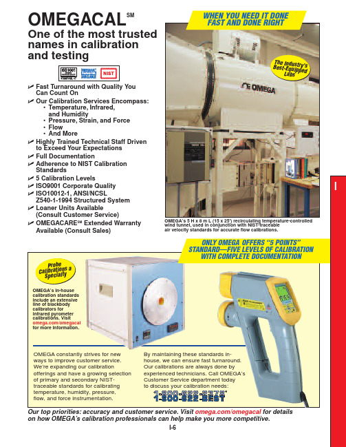
OMEGA constantly strives for new By maintaining these standards in-house, we can ensure fast turnaround.Our calibrations are always done by experienced technicians. Call OMEGA’s Customer Service department today to discuss your calibration needs:FAST AND DONE RIGHTT h e I n d u s tr y ’s B e s t -E q u i p p e d L a b s/omegacal for detailsCAL-1documents that the products you buy comply with the specifications printed in OMEGA’s handbooks. This calibrationCAL-2documents not only that theequipment you buy meets the published specification, but also that calibration CAL-3provides the same documentation as CAL-1/CAL-2 along with discrete test points of data and NIST-traceable testTemperature Calibration ServicesߜNIST TraceableߜAlways Meet or ExceedISO10012-1, ANSI/NCSLZ540-1-1994 StandardsߜFast Yet Preciseߜ5 Levels of Superior-Quality CalibrationߜOMEGA Will Calibratean Instrument or anEntire System (ProbeConnected to Instrument)For each of the calibration certificates OMEGA issues,we use different standards over varied temperatureranges to attain the highest quality and reliability.The standards we use for temperature calibrations arelisted in the table below; the standards that we selectfor a customer depend on the probe being calibrated.OMEGA meticulously maintains its in-house standardsso that our customers get the quickest, most convenient,and highest-quality calibrations available. For thosecustomers wishing to do their own calibrations, someof our standards are available for purchase. Visit/omegacal to learn more.For Calibration Services Call:OMEGA’s benchtop hot point®dry block probe calibrator modelCL900A ($3295) can be used to calibrate a handheld generalpurpose thermocouple probe and meter.Probe furnaces in OMEGA’s calibration laboratory are usedalong with NIST-traceable precision instrumentation to performtemperature calibrations renowned for their accuracy.Visit /temp-calfor details on ourcomplete line ofcalibration instruments.Calibration Block† Probe must meet requirements of calibration standards shown in table on previous page.* Prices are for new instruments and subject to change without notice. For recalibration, call Customer Service for price. Charges vary depending on the instrument being calibrated.Note: Because of the large selection of temperature probes, thermocouple wire andinstrumentation that OMEGA ®offers, the pricing and calibration data points shown above are examples only and do not apply to every probe or system calibration. Contact OMEGA Customer Service for advice before returning any instrument for calibration service.Ordering Example:CAL-3 (designate this calibration level when NIST traceability is required on the thermocouple probe or probe/instrument system you are purchasing new or when you are returning previously purchased equipment for calibration), $95 (probe only); $125 (probe with instrument).OMEGA can calibrate a probe by itself, an instrument by itself,or a probe connected to an instrument (system calibration). The pricing and temperature ranges listed below apply to most types of equipment; however, our product offering is so broad that you need to check with us for current pricing on a particular calibration. Be aware that there may be inherent limitations in a particular instrument that can restrict the temperature range over which it can be calibrated.Note:CAL-3 and CAL-4 also available on thermocouple wire. Upper temperature value may be limited by wire insulation.Note:CAL-3 calibration data is given in °C and °F.Visit /thermocouple for the complete selection of thermocouple probes available.Infrared Temperature Calibration ServicesߜAll Calibration Standards Used by OMEGA are NIST Traceable ߜChoose System orSensor-Only Calibrations—No Job is Too Small ߜ4 Calibration LevelsߜWide Temperature Ranges Covered—to 1648°C (3000°F) and Higher—When RequiredߜThe Industry’s Fastest,Most Reliable Blackbody CalibrationsNote: Because of the large selection of infrared pyrometers and blackbody calibration services that OMEGA offers, the pricing and calibration data points shown above are examples only and do not apply to every pyrometer or blackbody calibration. Contact OMEGA Customer Service before returning any instrument for calibration service.Ordering Example:CAL-3-IR (designate this calibration level when NIST traceability is required on the infrared pyrometer you are purchasing new or when you are returning previously purchased equipment for calibration), $125.BB-4A benchtop blackbody calibration source, $3595, below, shown calibrating as a system the OS1551-A infrared 4-wire transmitter, $690, and the DP41-B meter, $595.For Calibration Services Call:OMEGASCOPE $1195, with sighting scope,shown being calibrated using the OMEGA temperature blackbody calibration source, $9995.Visit to see our complete line of blackbody calibrators.OMEGA offers a complete range of infrared calibration services,performed by professionals with years of experience. As a company,our testing and calibration experience spans decades.OMEGA is an industry leader in temperature measurement and laser sighting technologies, with numerous patents and a global presence. Let our knowledge and technology work for you. Wemaintain an extensive line of high-temperature and low-temperatureblackbody calibration standards—all NIST traceable. Call our Customer Service department to arrange yournext infrared calibration.Relative HumidityCalibration ServicesCTXL-TRH, microprocessor-based,portable, temperature and relative humidity circular chart recorder,$795. See page S-38 for complete details.OMEGA’s highly accurate, temperature-compensated relative humidity calibration standards result in fast, stable, NIST-traceable calibrations. All work is performed by highly trained in-house technicians dedicated to superior-quality, economically priced service. We calibrate most of the relative humidity sensors, meters, controllers, recorders, data loggers, and data acquisition systems that we sell. Contact our Customer Service department to arrange calibration of your equipment.Note:Because of the large selection of relative humidity instrumentation OMEGA offers, the pricing and calibration data points shown above are examples only and do not apply to every relative humidity calibration. Contact OMEGA Customer Service before returning any instrument for calibration service.Ordering Example:CAL-3-HU (designate this calibration level when NIST traceability is required on the relative humidity instrument you are purchasing new or when you are returning previously purchased equipment for calibration), $125.NIST-traceable temperature/humidity chamber calibrates thermo-hygrometers and temperature and humidity products.ߜAccurate, Stable,Temperature-Compensated StandardsߜTraceable to NIST ߜExpert Technical Staff ߜFast, Economical ServicePressure Calibration ServicesNote:Because of the large selection of load cells and pressure instrumentation OMEGA/OMEGADYNE offers, the pricing and calibration data points shown above are only an example anddo not apply to every pressure calibration. Contact OMEGADYNE (1-800-USA-DYNE) or OMEGACustomer Service (1-800-622-BEST) before returning any instrument for calibration service.Ordering Example: EI-CAL-3-PRESSURE(designate this calibration level when NISTtraceability is required on the pressure transducer or when you are returning previouslypurchased equipment for calibration), $150.(Specify Calibration Level)Price Description$0Statement of conformance(must be requested at time of purchase)0Statement of traceability, no data points(must be requested at time of purchase) ߜNIST-Traceable StandardsߜSensor Calibration, Meter Calibration,and System Calibrations AvailableߜFast, Accurate Service by HighlyExperienced Engineering andTechnical StaffOMEGA/OMEGADYNE maintains highly accurateprimary deadweight standards that are NIST traceable.These standards are used directly or throughsecondary transfer standards for pressure calibrationsfrom vacuum to 75,000 psi. OMEGA/OMEGADYNEalso offers a wide selection of pressure sensors.Please consult your sales representative.NIST-traceablelow-pressure andForce/Load Calibration ServicesProvided by OMEGADYNEOMEGADYNE, located in Columbus, Ohio, maintainsin-house state-of-the-art NIST-traceable calibration standards for all your load cell calibration needs. Pictured above is ahigh-capacity deadweight tester (left) and hydraulic tester (right).“S” type load cell shown with DP41-S pressure indicator, $545.ߜNIST -Traceable Calibrations: 5, 11, and 21-Point Available ߜReliable, Accurate Certificates ߜSensor, Meter, and System Calibration Available: Tension,Compression, or BothߜHigh-Capacity Deadweight and Hydraulic Testers to 300,000 lbFor Calibration Services Call:orNote:Because of the large selection of load cells and pressure instrumentation OMEGADYNE and OMEGA offer, the pricing and calibration data points shown above are only an example and do notapply to every calibration. Contact OMEGADYNE (1-800-USA-DYNE)or OMEGA Customer Service (1-800-622-BEST) before returning anyinstrument for calibration service.Ordering Example:EI-CAL-3-FORCE(designate this calibrationlevel when NIST traceability is required on the load cell or when you are returning previously purchased equipment for calibration),$150.ߜFast Turnaround TimesNote: Because of the large selection of flow sensors, meters and instrumentation OMEGA offers, the pricing and calibration data points shown above are only an example and do not apply to every flow calibration. Contact OMEGA Customer Service before returning any instrument for calibration service.Ordering Example:CAL-3-FLOW (designate this calibration level when NIST traceability is required on the flow sensor or instrumentation when you are returning previously purchased equipment for recalibration), $225. Note: To request NIST-traceable calibration on new flow products, add suffix “-NIST”to the model number at time of purchase.OMEGA maintains a full line of standards for calibrating hot-wire anemometers and large vane-style handheld units. Pictured at the top right is our large wind tunnel,which is fully equipped with chillers,pumps, and condensers to keep therecirculating air at a constant temperature and flow ratewhile achieving flow rates from 25 to 9000 AFPM. This largewind tunnel is used for anemometer and vane-type sensor calibration.HHF141A microprocessor-based handheld air velocity meter, comes complete with 25 mm (1") dia. vane probe, flexible,straight and handle extension rods,1.5 m (5') cable, 3 “AA” alkaline batteries,hard carrying case and operator’s manual,$795. Visit /hhf141for details.with 25 mm (1") dia.vane (included).WTM-1000, OMEGA’s benchtop mini wind tunnel, $2995, shown with Flow Calibration Services。
- 1、下载文档前请自行甄别文档内容的完整性,平台不提供额外的编辑、内容补充、找答案等附加服务。
- 2、"仅部分预览"的文档,不可在线预览部分如存在完整性等问题,可反馈申请退款(可完整预览的文档不适用该条件!)。
- 3、如文档侵犯您的权益,请联系客服反馈,我们会尽快为您处理(人工客服工作时间:9:00-18:30)。
校准入门手册Omega白皮书引言如果不校准,最先进的工业设备也不会有太大作用。
通过校准,对一台设备进行的调整可以确保它按预期工作,可以确保我们可以依靠该设备提供可预见的、达到质量标准的精确结果。
本白皮书由Omega提供,它解释了什么是校准,为什么校准很重要,以及校准如何起作用。
其中对NIST可溯源性进行了定义和讨论,并且包括对基本校准的分步说明。
本文还讨论了企业内部校准与实验室校准,并介绍了主要校准设备类型。
什么是校准?简言之,校准是对设备进行调整以使其达到厂商规格的过程。
校准有时候也可以定义为发布数据。
这些数据包括报告或校准证书,它们向最终用户保证产品符合规格并且还可能符合外部标准,例如国际标准化组织的标准。
例如,该组织的ISO 9001标准为行业设定了全球性规格。
公司遵守这些标准,以确保其产品和服务为供应商和客户所接受。
校准的第二个定义称为认证更恰当。
有设备需要校准的公司可能把该设备送到计量/校准实验室,在那里,技术娴熟的技师使用自身必须达到严格校准要求的测量/测试仪器,将设备调整到符正在用来校准OS533E-DM红外线温度计的 OMEGA BB702高性能黑体校准源。
于该仪表在应用中的工作效果如何。
如果通过流量计的液体能够磨蚀或腐蚀,仪表中的零部件可能会在极短时间内损坏。
在有利条件下,同一流量计可能会持续工作数年而无需再校准。
然而,一般情况下,应该至少一年执行一次再校准。
当然,在重要应用中,再校准频率将更高合规格或者确认设备已经符合规格。
在工业过程中使用的全部或者一部分组件都可以校准。
例如,温度校准可能包括仅校准探头、仅校准仪器或者校准与仪器连接的探头(系统校准)。
一般而言,校准设备或校准器的精度至少要比被校准设备高四倍。
通常,设备有一个校准范围,技师在此范围内的不同数据点检查规格。
正如Mike Cable 在《校准:技师指南》中解释的那样,"校准范围定义为‘限值之间测量、接收或传送数量的区域,该区域通过声明范围下限值和上限值表示。
’ 限值由零位值和范围值确定。
零位值该范围的下限。
范围定义为范围上限值与范围下限值之间的代数差。
"在校准过程中进行的调整必须要在某些公差范围内。
这类公差表示相对设备规定精度的极小的、容许偏差。
以在企业内部进行、由第三方实验室进行或者由厂商进行。
再校准频率因设备类型而异。
例如,决定何时再校准一个流量计主要取决于该仪表在应用中的工作效果如何。
如果通过流量计的液体能够磨蚀或腐蚀,仪表中的零部件可能会在极短时间内损坏。
在有利条件下,同一流量计可能会持续工作数年而无需再校准。
然而,一般情况下,应该至少一年执行一次再校准。
当然,在重要应用中,再校准频率将更高校准器有哪些类型?校准器的形式和功能因它们要校准的设备而异。
用于校准红外线高温计(高温温度计)的黑体校准器通常有一个发射率极高的目标板,目标板的温度可以控制在极窄的公差范围内。
要校准高温计,将高温计测得的目标板的温度读数与目标板已知的受控温度进行比较。
接着,对高温计进行调整,直到两者之间的任何差异小到无关紧要为止。
用于校准测温探头的金属块校准器包括一个金属块,该金属块可以加热至精确温度。
这些温度与插入金属块内的测温探头得到的温度进行比较。
一般情况下测温探头无法调整,因此这一过程是一种校验过程,而不是真正的校准。
要校准盘装仪表和温度控制器等设备,常常使用一种称为参比信号装置的设备。
它是一种可以产生已知电信号的校准器。
这类设备可分为电压、电流和频率参比信号设备。
在其中一种校准器提供的信号进入相关设备后,就可对设备的显示值或输出值进行调整,直到其与已知信号相符。
模拟器是一种特殊的参比信号装置,它产生传感器输出。
通常,参比信号装置和模拟器都可以读取并且产生信号。
由于流化浴可提供安全、迅速的热传递以及精确的温度控制,它们可用于校准对温度敏感的设备。
流化沙浴温度探头校准器采用了流态化原理,当气体(通常是低压空气或氮气)向上流过部分填充有干燥、惰性氧化铝颗粒的舱室时就会出现液态化。
气体慢速流动,使颗粒运动起来,把它们分开,让它们悬浮起来并且达到稳态。
这让颗粒看起来如同湍流一般,像是沸腾的液体。
不仅流态化固体的循环和流动如同液体一样,它们还表现出优异的传热特性。
插入流化浴中的温度探头极其迅速地达到稳定温度,使校准更加简便。
冰点校准参比室中热电冷却元件提供非常精确、稳定的0˚C。
尽管参比室常用来校准或检验温度探头,但它们有能力模拟热电偶信号,这让它们可用来校准或者检验读取热电偶的仪器。
Omega的计量实验室拥有25'风洞,其中配有冷冻器、泵和冷凝器,可让再循环空气保持在稳定的温度和流速。
这种超大型设备用于校准风速计和叶片式传感器。
台式风洞的工作原理相同,可在尺寸大幅减小的测试段产生极其均匀一致的流速。
为什么校准很重要?1934年4月12日,新罕布什尔州华盛顿山顶峰上的一台风速计测量到有记录以来的最高地面风速:每小时231英里。
这个华盛顿山风速计已经在1933年经过校准,并在测得这次世界记录测量值后再次校准,结果证明它是精确的。
1997年12月,当一场台风席卷关岛后,该记录似乎被打破了,美国空军基地的一台风速计记录到时速达到236 mph的飓风。
然而该读数并未维持多久,因为美国全国极端气候委员会认定关岛风速计不可靠。
对于计量学专家来说,旧记录的继续存在是说明校准重要性的生动一课。
附注:据信,在龙卷风中出现过大于231 mph的风速,但是至今没要使一家公司符合ISO 9001标准,设备校准必不可少。
有记录设备承受得住这种极端天气。
与传言相反,华盛顿山风速计并没有在1934年那场风暴中吹走。
今天,它被保留在华盛顿山的Observatory Summit Museum博物馆中。
要寻找校准被忽视时会出现什么情况的更加现实的示例,只需看看冷冻食品烹制指南中的"烤箱温度可能会变化"这句话就行了。
出现这种警告的原因是大多数家用烤箱自从出厂后就也没有再次校准过。
显然,客户可以容忍这种误差幅度,但对于厂商却是不同。
要使一家公司符合ISO 9001标准,设备校准必不可少。
然而,仅规则本身并未解释为何最好的公司认识到经常正确进行校准的重要性。
以一家为客户生产金属杆件的公司为例,客户要在流程用到这种杆件。
假定,客户规定杆件的直径为1英寸,公差为±1/500英寸。
如果加工者用未经校准的游标卡尺测量杆件直径来检验其直径,他怎么能够充满自信地说他交付的杆件就是客户订购的杆件?其它行业必定有过这种同样的苦痛。
如果一家塑料制品厂商没有通过校准确保液态塑料在精确且正确的温度下进入注塑机,成品中就可能出现缺口或其它缺陷。
在 HVAC行业,空调机装有某种温度控制仪表。
如果厂商没有定期对照空调的实际输出校准该仪表,他将永远都不会知道他的设备是否发挥作用。
有人可能会问,为什么先进成熟的21世纪技术始终都离不开校准。
答案就是随着时间的推移,基本上所有设备的性能都会以某种方式降低,而作为制造过程中支柱的电子设备也不例外。
随着部件老化,设备丧失稳定性,并且偏离它们发布的规格。
即便是正常的搬运也可以对校准造成不利影响,野蛮操作无疑会使一台设备的校准彻底丧失(虽然其外表看上去完好无损)。
鉴于计划周密的校准方案在质量、生产率和收入方面带来的好处,其成本是合理的。
尽管小型校准任务完全可以在企业内部使用现成校准器进行,但将校准视作重中之重的大部分大中型企业会选择独立的计量实验室/校准实验室提供服务。
超大型公司可能会考虑向自动化设备投资,而不是执行大量日常校准,然而这类设备(与独立实验室使用的属于同一类别)的价格昂贵,并且还需要熟练技师操作。
如果还必须从外部认证权威机构获得认证,也会增加成本。
什么是NIST可溯源性?美国国家标准与技术研究院(NIST)隶属于美国商务部,它监督管理着测量标准与技术的发展,使之符合国际单位制(SI)。
NIST还承担着通过校准与其它服务将这些标准引入美国度量制的责任。
为了帮助美国工业符合国际标准,NIST还提供让企业可以确定测量结果可溯源性的实验室认可及其它方案。
根据NIST的定义,可溯源性为“需要建立一条与声明的基准值相比较的完整链条。
”该链条的链节包括由连续测量结果的值和不确定性组成的已记录比较。
链条中每次测量的值和不确定性都可以通过中间参照标准一直溯源到可溯源性所声称的最高参照标准。
据NIST称,术语“可溯源至NIST”为“测量结果可溯源至由NIST制订并维护的参照标准”的缩写。
NIST可溯源测量结果的提供者可以是NIST自己,也可以是其它组织。
NIST称每年有超过800家公司把它们的测量标准与NIST挂钩。
随后,它们可能在向客户提供测量服务、遵守法规以及增强质量保证过程中遵循这些标准。
NIST执行重量校准,但它并不是这种服务的唯一提供者。
NIST拥有维护美国国家质量标准的荣耀。
这一标准称为国家千克原器K20,它保存在NIST的保险箱中,是1889年授予美国的国际千克原器的精确复制器。
国际千克原器保存在位于法国的Bureau International des Poids et Mesures(国际计量局)的保险库内。
该原器含有90% 铂、10%铱。
千克在SI基本单位中是独特的,因为它仍由人工物体国际千克原器定义,而其它基本单位的定义则需要参照基本物理性质。
千克的原始定义为1升纯水在4˚C 及标准大气压下的质量,但结果证明在实践中该定义复制起来太难。
典型的校准包括哪些内容?称重系统可以很好地说明校准的一般准则。
阿基米德和达芬奇通过在机械杠杆上放置经过校准的砝码与未知重量达成平衡,从而确定其重量。
这种设备一处变动是使用了多个不同长度的杠杆,并用单个标准砝码来平衡。
后来,校准过的弹簧取代了标准砝码。
液压和电子(基于应变计)称重传感器的使用代表着称重技术中的第一次重大设计变革。
在当今的工厂中,电子称重传感器在大多数应用中受到青睐。
要检查传感器和称重传感器是否正常工作,用户必须回答以下问题:当系统中空无一物或者未加载时,重量显示值是否归零?在砝码加倍时,显示的重量是否加倍?当负载的位置变化时(负载不平衡)时,显示的重量是否保持不变?如果回答都为是,则称重传感器及传感器有可能状况良好。
在校准之前,应该按照下面的方式检查机械系统以及称重传感器的安装:∙检查称重传感器的电缆,并且把电缆盘起来,不要出现多余电缆。
∙如果称重系统包括多个称重传感器,应该将负载均匀分布。
如果称重传感器之间的差异超过10%,应对负载进行重新平衡并且使用垫片调整。
∙在校准过程中,用户应该能够举起容器,同时不会使其它称重传感器卸载或过载。
系统设计应该考虑到升高以及水平拆卸称重传感器的需要。
对容器进行校准时,需要用吊架或支架支撑住校准砝码。