欧米茄手表完全服务的步骤及欧米茄保修服务
欧米茄表使用说明书
如何确定我购买的是正宗欧米茄腕表?遵循如下步骤可以确定您购买的是正宗欧米茄腕表:- 只在欧米茄指定经销商处购买欧米茄腕表。
- 申请一张信用卡大小的保修卡,完整填写8位系列编号、手表编号以及经销商的完整姓名和地址。
- 如果您想确定腕表是否正宗,请携同欧米茄腕表及保修卡到指定的维修中心,让我们的维修服务员确定您购买的是否为正宗欧米茄腕表。
客户服务网络返回页首计时表(CHRONOGRAPH)与瑞士官方天文台认证腕表(CHRONOMETER)有何区别?计时表(CHRONOGRAPH)带有显示时、分和秒的指针,它们与机械系统一起透过中央计时指针测定逝去时间,可以记录到秒,并且具有30分钟和12小时定时装置。
瑞士官方天文台认证腕表(CHRONOMETER)是以不同角度,成功通过温度、精确度和防水功能测试后,获得COSC(瑞士官方天文台)正式颁发的等级证书的腕表。
通过这些测试至少需要15天时间。
返回页首计时腕表上的按钮具有什么功能?位于2点钟位置的按钮可以启动或停止计时功能,位于4点钟位置的按钮用于重新计时。
返回页首海马系列专业计时腕表的排氦气阀门具有什么功能?排氦气阀门由欧米茄为职业潜水员专门研发。
在深海潜水过程中,潜水员往往会在潜水钟内进行数天作业。
在到达水平面之前,潜水钟内充满氦气和氧气的混合气体。
氦气分子轻于空气,可以渗入手表,并在大气压力的作用下将水晶镜面推出。
在到达水平面之前打开氦气排放阀可以将氦气排放,从而防止手表进水。
返回页首自动上链机芯与手动上链机芯有何区别?自动上链机芯与手动上链机芯的区别在于上链方式的不同。
手动上链腕表需要每天人工上链,而自动上链腕表则具有内部摩打,利用手腕的运动来自动上链。
自动上链腕表通常具有至少40小时的动力储存,即使不佩戴手表,仍然能够备有足够的能量储存以保持稳定的运行。
返回页首欧米茄腕表是否具有防振功能?是。
欧米茄腕表可以承受重量为5000克的振动。
返回页首欧米茄腕表是否具有防磁性能?是。
欧米茄官方授权维修点-欧米茄官方售后
欧米茄(OMEGA)官方客户服务中心北京市西城区西单北大街甲131号西单大悦城写字楼7层702室温馨提示:欧米茄售后服务中心从创立之初就秉承精益求精顾客至上的理念。
专业化客服全天候在线为您解答时计问题。
服务中心配备先进的专业检测工具、维修设备及仪器仪表,标准的受理大厅,独立的VIP客室,舒适的休息区,以科学的维修技术,贴心的周到服务,诚信的职业操守,为您提供优质的欧米茄时计维修服务。
现在预约成功,即可尊享9折优惠!欧米茄(Omega)是国际著名制表企业和品牌,英文名omega,代表符号“Ω”。
由路易士·勃兰特始创于1848 年,拥有超过150年的悠久历史。
欧米茄(W)是希腊文的第二十四个,也是最后一个字母。
它象征着事物的伊始与终极,第一与最后。
代表了"完美、极致、卓越、成就"的非凡品质,诠释出欧米茄追寻"卓越品质"的经营理念和"崇尚传统,并勇于创新"的精神风范。
下面就让我们一起来看看欧米茄手表该怎么保养。
腕表的使用要使手动上链腕表开始运转,您只需要通过旋转表冠来上紧发条直至您感到有明显的阻力为止。
如果您的欧米茄是一款自动腕表,同样可以先手动旋转表冠为机芯上链让指针开始运转,然后让机芯的自动上链系统来做余下的事情就可以了。
请注意千万不要为自动腕表过度上链,因为在满链的情况下,自动腕表的表冠并没有明显的阻力点。
欧米茄(OMEGA)官方客户服务中心北京市西城区西单北大街甲131号西单大悦城写字楼7层702室如果需要更改欧米茄腕表的日历,只需拔出表冠进行旋转,将指针转过12点直至日历更改,接着回拨指针至三或四个小时前,您会听到一声很轻微的“咔嚓”,随后再次转动指针跨过12点直到您能看到正确的日历为止。
如果是在下午或傍晚调校日历的话,请记住在更改日历后一定要将指针转到正确的下午时间。
每一年您都需要为腕表检测一次防水。
如果您的腕表的防水等级是3 ATM(30米),我们建议您在洗澡或游泳的时候先摘下。
北京欧米茄售后维修网点

欧米茄售后维修服务中心已在中国一二线城市逐步设点,北京服务站点地址:北京西单大悦城写字楼,为欧米茄提供检测保养和维修服务。
欧米茄为世界顶级体育赛事提供专业计时技术而享誉全球。
高尔夫、游泳、田径、有舵雪橇和帆船等体育项目更奠定了欧米茄的品牌元素。
一百五十年以来,欧米茄手表稳占世界制表业的先锋位置,奠定了骄人成就。
欧米茄手表分为两大类:一是石英,二是机械。
机械表又分为两种:手动上弦及自动上弦手表。
机械表允许的误差范围为三十秒/日,经过天文台认证的机芯平均误差范围在负四秒至快六秒/天之间,具体的误差根据手表所使用的机芯而定,并非按照价格越高误差越小的原则。
自动机械表的动力来源佩戴者手腕的摆动产生能量给发条上弦,一只完全上条的自动机械表可持续运行三十六小时左右:如保证每天正常佩戴的情况下,可运作十五小时左右,如超过以上的时间不戴或摆动不足(佩戴者的运动量少)都将引起手表的停走,再次佩戴前应先给手表上足发条。
机械表依靠内部的机械装置来控制手表的均匀准确地走时,这些机械装置是会受到地心引力,环境温度等影响引起误差,一般机械表的误差是按天来计算的,根据机芯的型号和制造品质不同而有所差异。
欧米茄手表为什么会有走时误差呢?出现误差可能有以下几种情况:下面由欧米茄维修的师傅介绍!欧米茄手表走时误差的情况(1)手表的精准度根据手表的机芯类型不同而有所差异。
欧米茄石英表就是以石英振动器取代机械表中的摆轮,利用其正确的高速振荡来计时的,欧米茄维修提醒一般而言石英表的精确度较高,瑞士标准是月误差在十五秒之内,有些精准的机芯更是可以达到年误差几秒之内。
(2)欧米茄机械表依靠内部的机械装置来控制手表的均匀准确地走时,这些机械装置是会受到地心引力,环境温度等影响引起误差,欧米茄维修提醒一般机械表的误差是按天来计算的,根据机芯的型号和制造品质不同而有所差异,一般每天误差三十秒以内的都属于正常范围。
一些较高精准度的机芯,如天文台系列可以达到十秒左右。
Omega产品支持信息书说明书
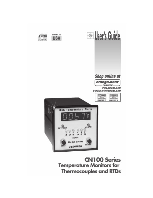
TABLE OF CONTENTSCNIOO SERIES TEMPERATURE MONITORSSECTION PAGESECTION 1 INTRODUCTION1 1.1General Description1 1.2Available Models1SECTION 2 INSTALLATION3 2.1Unpacking3 2.2Controller Location3 2.3Mounting3 2.4Wiring Power Circuit4 2.5Sensor Placement4 2.8Setup Procedure5SECTION 3 OPERATION63.1Operation6 3.1.1Controls and Indicators6 3.1.2Relay Output7 3.2Adjusting Setpoints7 3.3Adjusting Scan Time7 SECTION 4 SERVICE INFORMATION74.1Maintenance7 4.2Test Procedure7 4.2.1Visual Inspection7 4.2.2Functional Observation7 4.2.3Calibration Temperature9 4.2.4Calibration Alarm10 4.2.5Zone Crosstalk10 4.3Troubleshooting11SECTION 5 SPECIFICATIONS125.1Thermocouple12 5.2RTD13 5.3Parts List14 5.4Calibration Charts17 5.4.1Calibration Table 0-20000F-Type K18 5.4.2Calibration Table 0-5000F-Type K19 5.4.3Calibration Table 0-2500C-RTD20 5.5Component Layouts21 5.8Schematic231SECTION 1 INTRODUCTION1.1GENERAL DESCRIPTIONThe OMEGA® CN100 Series temperature monitor is a tempera-ture indicator with either high or low alarms. The six input channels accept independent thermocouple inputs, and there is an individual setpoint for each channel. In operation, the CN100will scan each channel for 4 to 12 seconds (via side adjustment),and the display will indicate the temperature measured by the individual thermocouples. A red LED indicates an alarm condi-tion; in the event of an alarm, scanning is halted and the relay de-energizes, until the manual reset button is depressed. The CN101 models are high temperature alarms, while the CN102units will alarm on low temperatures.The CN102 models also feature a built-in cold start alarm suppression. When the “START UP” LED is lit, the alarm action is suspended until the temperatures of each input reach their respective setpoints. Power failures for less than 30 minutes do not affect the start-up operation.1.2AVAILABLE MODELSCN101(*)-(**) HIGH ALARMCN102(*)-(**) LOW ALARMRTD#2SECTION 2 INSTALLATION2.1UNPACKINGRemove the packing list and verify that all equipment has beenreceived. If there are any questions about the shipment, pleasecall OMEGA Customer Service Department.Upon receipt of shipment, Inspect the container and equip-ment for any signs of damage. Take particular note of anyevidence of rough handling in transit. Immediately report anydamage to the shipping agent.NOTEThe carrier will not honor any claims unless allshipping materiel is saved for their examination.After examining and removing contents, savepacking material and carton in the event reship-ment is necessary.2.2CONTROLLER LOCATIONSelect a location for the controller that is free from excessiveshock, vibration, dirt, moisture, and oil. The ambient tem-perature should be between 30° and 130°F(-1° and 54°C).2.3MOUNTINGMount the controller into a 3 5/8” (92mm) square cutout. Referto Figure 2-1 for the cutout and case dimensions. The plug-in controller does not have to be removed from its housing formounting.Remove the two screws that hold the mounting slides; thenremove the slides. Insert the case into the cutout from thefront side of the panel and reinstall the two slides and twoscrews. The length of the slides must be reduced if the con-troller is to be mounted in an extra thick panel. If the control-ler has been unplugged from its housing, the top of the hous-ing can be determined by the serial tag.3.4Figure 2-1. Outline Dimensions2.4WIRING POWER CIRCUITThe controller operates on either 120 or 240 VAC, 50 to 60Hz line voltage when connected to the proper terminals.Incoming power lines should be properly fused. Refer to Figure 2-2.NOTE Fuse incoming high side of line with fast blow fuse of appropriate rating. Shorted heater or wiring will destroy the relay or output Triac.2.5SENSOR PLACEMENTProper sensor placement is essential. It can eliminate many problems in the total system. The probe should be placed so that it can detect any temperature change with little thermal lag. In a process that requires fairly constant heat output, the probe should be placed close to the heater.In processes where the heat demand is variable, the probe should be close to the work area. Experimenting with probe location can often provide optimum results.In an ice bath process, the addition of a stirrer will help to eliminate lags. Some RTD’s are shock sensitive andrequire care in handling and installation.2.2SET UP PROCEDUREWire the instrument as shown in Figure 2-2. Observe polarity(on the thermocouples red is always negative, on RTDs blackis negative) and short all the unused zone inputs (do not shortthe analog output). Turn all the setpoints fully CW on CN101models and CCW on the CN102 models. Power up theinstrument. If any zone alarms, check for open thermo-couples or setpoints turned the opposite way. Correct theproblem and push the RESET button. Observe the scanningrate and readjust if needed at the side of the instrument. Pushthe SET button and release. The green light should appear forabout 10 seconds and the display indicates the setpoint Adjustthe setpoint of the indicated zone to the desired alarm tem-perature. If more time Is needed, push the SET button to getan additional 10 seconds. Wait for the green light to disappearand repeat the procedure for all used zones. For unusedzones, leave the setpoints fully CW for CN101 models andfully CCW for CN102 models.Figure 2-2. Wiring Diagram56SECTION 3 OPERATION3.1OPERATIONThe typical control system contains the sensor, controller and the process. The thermocouple sensor produces a small voltage change proportional to the measured temperature of the process. An RTD produces a change in resistance proportional to the measured temperature of the process.This is linearized in a unique active circuit, and amplified by the controller, where it is compared with setpoint temperature. If the temperature of the sensor is above setpoint, the output circuitry will be actuated. This is indicated by means of an LED light. The digital meter displays the sensor’s process tem-perature, and when switched, displays the alarm setpoints.Six zones share common amplifier and display.3.1.1Controls and Indicators (Refer to Figure 3-1)1.LED Display (temperature or setpoint)2.Setpoint (displayed by green LED)3.Start Up button—cold start (CN102 only)4.Alarm Light (red LED)5.Zone Light (yellow LED)6.Setpoint Control7.Setpoint Enable8.Manual Alarm Reset9.Scan Time Adjust 10.Calibration LO and HI potentiometers3.1.2RELAY OUTPUTThe output relay has SPDT contacts rated 5 amps at 120Vand 3 amps at 240 VAC. These contacts can be wired toprovide power to the alarm. This is a latching relay.3.2ADJUSTING SETPOINTSSix setpoint adjustments are located on the faceplate. Theseare 15-turn potentiometers with slotted shafts. A small screw-driver is required.3.3ADJUSTING SCAN TIMEThis adjustment is located on the side of the instrument. It is a15-tum potentiometer with slotted shaft CW rotation in-creases the scan time.SECTION 4 SERVICE INFORMATION4.1MAINTENANCESome simple preventative maintenance will keep thecontroller operating properly:1. Keep the controller clean and protected from dirt, oil andcorrosion.2.Periodically recheck all electrical connections.4.2TEST PROCEDURE4.2.1Visual Inspection1.Inspect the instrument for mechanical damage.2.Make sure that all screws are tight.3.Make sure all switches and lights are properly installed.4. Make sure all labels are properly and correctly attached. 4.2.2Functional Observation1.Short the thermocouple or RTD inputs to each zone.2.Attach cord and plug to 120 VAC line terminals.3.Attach ohmmeter to C and NO relay terminals.4.Insert the power cord to 120 VAC line outlet.5.Observe that ohmmeter reads near zero ohms.6.Observe that digital display is “on” and all the digits areworking properly.77.Observe that only one scan light is on.8.Observe that digital display reading is more than zero andless than 1000F (or 0C).9.Adjust LO calibration potentiometer on the side of theinstrument until the display reads 75 ±50F (25 ±50C). Refer to Figure 4.1.10.Turn all setpoint controls 10 turns clockwise.11.If the alarm light (red) is on, push the RESET button andremove the alarm.12.Observe that zone light scans sequentially from zone tozone without skipping any zones.13.Turn the scan time control fully CW (about 20 turns) andobserve that the scan rate is more than 12 seconds.14.Turn the scan time control fully CCW and observe that thescan rate is between 2-5 seconds.15.Set the scan time at 5 seconds ±1 second.16.When the scan light comes to zone 1, push the set switchand observe that the green setpoint light comes on. Ob-serve that the light stays on for 7-15 seconds and the zone scan light stays on zone 1 as long as green light is on. 17.Push the SET button and turn the setpoint control fullyCCW; observe that indication goes to 0000 -0 +2.18.Observe that the alarm light comes on and ohmmeterresistance measures HI (open).19.Push the SET button and turn the setpoint control fully CW.Observe that the display rises gradually from 0 to full range of the instrument.20.Push the RESET button and observe that the RESET lightis off and the instrument resumes scanning.21.Repeat steps 17 through 20 for other channels.22.Switch the power on and off several times and observe thatthe unit does not go to alarm condition.23.Disconnect the thermocouple short from zone 1 andobserve that when the scan light comes to zone 1, theinstrument indicates alarm, the meter reeds full scale, and the scanning has stopped.84.2.3 Calibration Temperature1. After the instrument has been warmed up for 15minutes,attach proper thermocouple or RTD wire to zone 1.2.Connect the other end of the wire to the thermocouplesignal generator. Select proper cold junction compensa-tion. Refer to Figure 4-2. For RTD version use precisiondecade resistance box.3.Bring the instrument to alarm condition by setting themillivolt or resistance signal higher than the range of theinstrument. This will stop the scanning and keep theinstrument latched to the zone being calibrated.4.Set the millivolt source or decade resistance box to lowcalibration point as indicated on the calibration tables.5.Adjust the LO calibration potentiometer on the side ofthe instrument to read the proper typical value ±10F or±10C.6.Set the millivolt source or decade resistance box to highcalibration point as indicated on the calibration tables.7.Adjust the Hi calibration potentiometer on the side of theinstrument to read the proper typical value ±1 0F or±10C.8.If large adjustments are made on HI calibration potenti-ometer, repeat steps 4 through 7 until all errors areeliminated.9.Check all calibration points on the table to be within±.25% of the typical calibration.10.Measure that the DC voltage output corresponds to thecalibration table. For RTD version, check resistanceoutput.910Figure 4-2. Thermocouple Calibration4.2.4Calibration Alarm1. Push the SET button and adjust zone 1 setpoint to mid-range.2. Set the temperature input to .25% of range below the setpoint.3.Push the RESET button and allow the scan light to go to zone2.4.Set the input to zone 1 to .25% of range above the setpoint.5.Observe that when the zone light comes to zone 1, the unit goes into alarm condition within 4 seconds.4.2.5Zone Crosstalk1.Set zone 1 setpoint to full range.2.Set zone 1 temperature to 90% of its range.3.Set zone 2 setpoint to .25% of range above its shorted thermocouple temperature.4.Reset alarm if necessary and allow the unit to scan.5.Observe that zone 2 does not alarm.SYMPTOM1. instrument isinactive2.Display reads fullrange unit inalarm no scanning 3.No output, unit inalarm4.Reading is zero5.Reads ambient6.Alarm does notreset7.Does not readsetpoints8.Erratic indication9.Cannot reachrange10.Cannot adjustscan rateCORRECTIVE ACTIONCheck line voltageReplace fuseClean terminalReplace power trans-former.Check probeReplaceCheck relay.Clean or replaceCheck and correct.Check and correct.Check and replace.Tighten or replace.Check cable.Check ±12V regulators.Check 5.03V ±.02;adjust if necessary.Replace potentiometer PROBABLE CAUSENo line voltageBlown fuseDirty screw terminalOpen transformerprimaryOpen thermocoupleprobe or RTD probeBurned input l.C.Relay contacts orrelay coilReversed thermo-couple leadsShorted thermocoupleBroken or jammedreset switchBroken or looseswitchLoose ribbon cable.Power supply faulty5V ReferenceBroken potentiometer11SECTION 5 SPECIFICATIONS 5.1THERMOCOUPLEALARM TYPEACCURACY:INPUTS:NO. OF SETPOINTS:SCANNING RATE:RELAY:ANALOG OUTPUT:ALARM OPERATION:RESET:MAX. VOLTAGE BETWEEN INPUTS: POWER:POWER LOSS:DISPLAY:AMBIENT OPERATING RANGE: DIMENSIONS:PANEL CUTOUT:DEPTH BEHIND PANEL: TERMINALS:CN1O1 models-high alarm; CN1O2 models-low alarm±1% of range6, thermocouple6, independent for each input4 to 12 seconds per channel, side adjustmentSPDT Mechanical, rated 5A at120 VAC, 3A at 240 VAC latching 0 to 5 VDC, scans sequentially from zone to zone (non-isolated)Relay de-energized. ALARM ON LED indicator on, scan hold until reset Manual, front pushbutton10 VDC or 6 VRMS120/240 VAC, 50/60 HzUnit returns to ready state4-digit LED, 0.6”32 to 1350F3.56”H x 3.56”W x 6.25”D1/4 DIN, 3.622” x 3.622”6.25”Type 6-32 screws125.2RTDACCURACY:INPUTS:NO. OF SETPOINTS:OPEN SENSOR INDICATION: SCANNING RATE:RELAY:ANALOG OUTPUT:ALARM OPERATION:RESET:MAX. VOLTAGE BETWEEN INPUTS: POWER:POWER LOSS:RESOLUTION:DISPLAY:AMBIENT OPERATING RANGE: DIMENSIONS:PANEL CUTOUT:DEPTH BEHIND PANEL: TERMINALS:Greater than 0.5% range ±1RTD 100 ohm Platinum (European)—2 wire “Top” input connector—common to all 6 channels (negative wire). “Bottom” input connector—single inputs to each channel (positive wire)6, independent for each input Treated as alarm4 to 12s per channel, side adjustment Mechanical, rate 5A @ 120 Vac(24 Vdc), 3A @ 240 Vac (48 Vdc); SPDT type0 to 5 Vdc, non-isolatedRelay de-energized, ALARM ON LED indicator on, scan hold until reset Manual, front pushbutton10 Vdc or 6Vrms120/240 Vac, 50/60 HzUnit returns to ready state after power resumption104-digit LED, 0.6”32 to 1350F3.56” H x 3.56”W x 7” D¼ DIN, 3.622” x 3.622”6.25”Type 6-32 screws135.3PARTS LISTP.C. Board-ARESISTORS 1/4 WATT1-220 ohm (R26)2-1K (R6, R22)4- 1.5K (R9, R10, R11, R12)1- 2.2K (R17)1- 2.7K (R16)6- 4.7K (R4, R7, R8, R24, R29, R30)7-10K (R2, R3, R5, R13.2, R14. R15, R23) 1-8.2K (R27)1-18K (R28)1-33K(R1)1-66K (R19)1-lOOK (R20)1-470K (R25)PRECISION RESISTORS:1 ‘ 400K(R18)POTS:1-2K (P3) (89PR)2-1OOK (P1, P2) (89PR)CAPACITORS:1-68pF (C3)1-220pF (C2)1-4700 pF(C4)3-0.01uF (Mylar) (C5, C8, near Q14)1- 2.2/50V (C7)1-10/25V(C6)2-10/50V (C9. C10)1-100/25V (C1)2-100/50V (C13. C1411-1000/16V (C12)DiODES:9-1N4148 (D1, D2, D3, D4, D5, D6, D7, D8, D9) 4-1N4004 (D0, D11, D1Z, D13, D14)TRANSISTORS:7-2N4424(Q2,Q3, Q4, Q5, Q7, Q23, Q24) CRYSTAL:1 ‘ 3.579514INTEGRATED CIRCUITS:1-741 (Q19)1-311 (Q18)3-4518(Q 8,Q12, Q13)2-4028 (Q1, Q16)2-4040(Q11, Qi4)2-4052(Q9, Q10)1-4066(Q17)1-4011 (Q6)VOLTAGE REGULATORS:1.317LZ (Q22)1-7812(Q20)1-7819(Q21)RELAYS:1- 5 AMP Relay MS64-932TRANSFORMER:1-830957HEADERS:1-4161-14-03-P1 (Straight)1-4162-22-06-P1SOCKETS:2-16 Pin MEGA 16MPCONNECTOR:1-4002-14-00-P5P.C. Board-BPRECISION RESISTOR 1%:11K (R52)1-250K (R53)1-174K(NearP10)POTS:1-200 ohm (P10) 89PR7-10K (P4, P5, P6, P7, P8, P9, P11) 89PR15CAPACITORS:1- 2.2/50 (C25)1- 4.7/50V (C22)4-22/50 (C15, C16, C19, C23)RESISTORS 1/4 WATT6-100 ohm (R76, R77, R78, R79, R80, R81)7-1K (R29, R49, R56, R57, R58, R62, R63)1- 1.5K (R72)1- 2.2K (R64)2- 4.7 (R74, R83)5-10K (R27, R51, R59, R67, R69)17-33K (R32, R33, R34, R37, R38, R39, R40, R45, R47, R48, R50, R54, R55, R60, R61, R68, R70)3-100K (R28, R46, R91)1-220K(R35)-330K (R30)2- 1 Meg. (R36, R41)1- 1.5 Meg. (R42)2-10 Meg. (R65, R66)DIODES:6-1N4148 (D15, D16, D18, D19, D20, D23)6-1N751, 1N753 or 1N754 (Z2, Z3, Z4, Z5, Z6, Z7) TRANSISTORS:1- 2N4424 (Q29)INTEGRATED CIRCUITS:3-4051(Q24,Q30,Q31)2-uA339 (Q25,Q26)1-4066(Q27)I-0P20 (Q28)HEADERS:1-14 PIn #4161-14-03-Pi (Straight)SWITCHES:2-C&K8168(S1,S2)2-BIackCaps80252-Metal Guards G-12A2-WashersBARRIER CONNECTOR:1-A204207NLR501-A20720NLR5316CONNECTOR:1-4002-14-00-P51- Cable #455-240-14PC Board-CRESISTOR 1/4 W:7-47ohmLED’s:1-Red (MV5754)1-Green (MV5454)6-Yellow(MV5354)DISPLAY MODULE:2-MAN6740HARDWARE:1-Case1-Backplate1-Bezel1-Face Plate (Metal)1-Face Plate (Plastic)1-SprIng4-3/8” x 5/32” F/HD Screws4-3/8” x 5/32” R/MD Screws2-5/32 Nuts1-Red Lens5.4CALIBRATION CHARTSThe following charts are sample calibration charts for theranges 0-5000FJ, and 0-20000FK. For models other than theseranges,it is advisable to calibrate the units at 10% and 90% FS.1718CN101(*)-(**)5.4.1CALIBRATION TABLE 0-2000°F-TYPE-KRANGE COMPONENTSR13.4-10K R18-400K 1%R62- 1.5K R63- 2.2K R64- 1.3K R73-43K R84-13.3K R85-27K R86-110K 1%195.4.3CALIBRATION TABLE 0-500°F-TYPE JRANGE COMPONENTSR13.2-10K R18-400K 1%R62-1K R63-1K R64- 2.2K R73-33K R84-OUT R85-10K R86-350K 1%20NOTES Actual temperature rounded off to whole digit (no decimal point). Accuracy better than 0.5% of 250C-2250C range.Recommended lead wire distances to obtain stated accuracy with proper calibration. Use copper wire. Based on ambient temperature.AWG Distance 14150ft 2050ft 2425ft5.4.3CALIBRATION TABLE 0-250°C-RTD275.5COMPONENT LAYOUT-P .C. Board A1.Select nearest standard range resistor (e.g. 800° = R13.3).2.Set setpoint pot full CW (maximum).3.Adjust P2 for required range readout.4.Reduce R18 If range cannot be reached.5.5COMPONENT LAYOUT-P.C. Board B5.6SCHEMATICM0666/0702。
福州欧米茄售后维修保养中心

欧米茄售后维修服务中心已在中国一二线城市逐步设点,福州市服务站点地址:福州市鼓楼区恒力城写字楼,为欧米茄提供检测保养和维修服务。
欧米茄(OMEGA)是瑞士著名钟表制造商,英文名OMEGA,以希腊字母“Ω”命名。
欧米茄由路易士·勃兰特(Louis Brandt)创始于1848年。
长期使用手表与您的日常维护密不可分。
通常,你不关心、不爱护。
如果不进行维护,则会缩短手表的使用寿命。
每天你都要尽可能地照顾好你的手表。
每年你都要做大幅度的加薪。
建议去专业的官方售后做了检查,有利于手表使用年限,其下是官方售后帮您介绍一下日常生活中佩戴手表时需要注意的问题。
1、清洁摆轮与游丝摆轮与游丝可说是机械表的心脏,运转久了摆轮车芯会堆积油泥,游丝也会因沾黏油垢而导致摆频不正常。
摆轮清洁首先从轴芯开始,以手指轻轻夹起摆轮轴芯朝上的部份(半浸于去渍油中),然后以削尖的软木棒沾去渍油小心清理轴芯、月石与摆轮上的积污,这里要注意动作须非常轻柔,以免使游丝变形。
2、接下来将摆轮翻面,以毛刷沾去渍油轻轻刷洗避震器、宝石座与摆轮表桥至其光亮无垢为止;再来是游丝部份,千万要注意不能以毛刷或其它工具来清洁,否则会造成游丝变形,正确的方式是以镊子夹起摆轮表桥,并将游丝伸展开来置于去渍油中轻晃,以洗去附着在上面的油污。
将以上的零件再放入另一个干净的去渍油盘中重复以上动作,然后置于白纸上晾干。
3、清洁发条盒与螺丝发条盒是机械表的动力来源,也是油上最重的地方,所以与螺丝共列为最后清洗的部份。
首先将发条盒盖板拆卸下来,然后将包含螺丝在内的所有零件浸泡在去渍油盘中约10分钟,之后开始刷洗发条盒与螺丝,并以削尖柳枝清理发条盒孔,读者们或许会疑问为何不将发条卸下清理,其实以目前发条材质的进步,除非跑水进去,否则几乎是不会生锈的,所以到官方售后中心洗油时只需浸在去渍油中稍微刷洗即可,并不需要拆卸。
温馨提示:以上就是欧米茄服务中心的专业技师给我们讲解的有关欧米茄手表的知识,欧米茄售后服务中心从创立之初就秉承精益求精顾客至上的理念。
欧米茄腕表上发条的两大技巧-北京欧米茄维修中心

欧米茄(OMEGA)是瑞士著名钟表制造商,英文名OMEGA,以希腊字母“Ω”命名。
欧米茄由路易士·勃兰特(Louis Brandt)创始于1848 年。
欧米茄从海洋探险的传奇故事中得到灵感,在2005年的时候推出了海马系列海洋宇宙腕表。
但是欧米茄并未将这一系列拘泥于男士腕表,同时也为现代女性打造刚柔并济的精美时计,硬朗的造型以及时尚的色彩搭配十分吸睛,展示出了现代女性独特的魅力。
欧米茄和海洋之间有着深厚的渊源。
追溯从前,伟大的探险家比如威廉彼比、雅克库斯托以及雅克马犹都曾经佩戴过欧米茄潜水腕表。
这款全新的海洋宇宙600米腕表在精准度、性能和防磁上都通过了严苛的测试,防水深度可达600米。
超高颜值加上超强性能,全新的海洋宇宙600米腕表可谓是吸引力十足。
欧米茄以庄重、实用、不显浮华的风格广受成功人士喜爱。
欧米茄品质精良,工艺精湛,糅合尊贵、典雅和独特气质于一身,位列世界手表业之翘楚,被称为精确的代名词。
备受全世界各界人士的推崇,更深得收藏家们的青睐。
欧米茄腕表上发条的两大技巧:一、首先,要在没有上发条的欧米茄手表上做检验,如果欧米茄手表没有上发条你可以用手摇晃欧米茄手表在观察手表的秒针的走动情况,如果秒针在很短的时间内走完,那么说明手表上满发条后能全部走完,灵敏度很好,如果秒针长时间走那么说明手表上满发条后不能全部走完,说明灵敏度不好;二、其次,如果是上过发条没有走完的欧米茄手表,可以转动发条,观察秒针的走动情况,上条转动的越少,秒针起动的越早则说明手表的灵敏度很高,相反,则说明手表的灵敏度不好,灵敏度高的手表上足发条后会走好长时间。
温馨提示:以上就是欧米茄服务中心的专业技师给我们讲解的有关欧米茄手表的知识,欧米茄服务中心为提高中国区客户服务体验,服务地区覆盖北京、上海、广州、深圳、等全国各大城市,在全程维修过程中严格实施无尘、抗氧化等规范操作,同时欧米茄引进瑞士先进设备,独立的VIP客室,舒适的休息区,维修人员先后接受了顶级制表师的专业培训,同时掌握的先进核心技术为维修服务提供了切实的保障,赢得了广大消费者的信赖,同时为您提供优质的欧米茄时计维修服务。
珠海欧米茄特约售后服务中心站

温馨提示:目前中国欧米茄售后维修服务中心已围绕国内一二线城市逐步设点。
欧米茄售后服务中心从创立之初就秉承精益求精顾客至上的理念。
专业化客服全天候在线为您解答问题。
在日常戴表的同时,我们难免会弄坏或者弄脏自己的爱表,手表保养是十分必要的,对延迟手表寿命和良好的机芯状态都会有相当的帮助。
无论您的腕表有任何问题,售后服务中心都会为您的腕表保驾护航。
欧米茄手表是一种精密仪器,方寸之内的大小零件上百个,独有的复杂结构,使它的保养显得尤为重要。
从小白到慢慢爱上手表,除了会发现自己懂得越来越多之外,与手表感情也越来越深了,我们除了欣赏手表的美,我们也要学会如何去保养它。
方法一:普通欧米茄机械手表受了潮,可用几层卫生纸或易吸潮的绒布将表严密包紧,放在40瓦的电灯泡附近約15厘米处,烘烤约30分鐘,表內水汽即可散去。
切忌将手表的表蒙靠近火直接烘烤,以免使表蒙受熱变形。
方法二:将表蒙朝內、底盘朝外,反戴在手腕上,两个小时后即可消除。
如果进水严重,最好立即送表店擦油,清除机心的水分,以避免零部件生锈。
方法三:用颗粒状的硅膠与已经积水的欧米茄手表一起放进一个密封的容器內,数小时后,取出手表,积水即全部消失。
此法简单经济,对表的精度和寿命均无任何损害。
已经多次吸水后的硅膠,可在120下干燥数小時,吸水能力可再生,还能反复多次使用。
温馨提示:以上就是欧米茄服务中心的专业技师给我们讲解的有关手表的知识,售后服务中心从创立之初就秉承精益求精顾客至上的理念。
专业化客服全天候在线为您解答问题。
北京欧米茄维修中心-欧米茄表长期不戴时的注意事项
精美的腕表设计,精准的走时,悠久的历史,吸引了众多消费者的目光,如果您佩戴了一段时间的手表放在一边不戴了,是需要定期进行保养的,这才能维持您手表原本的手表性能。
下面我们一起了解一下欧米茄手表长期不戴的注意事项及保养方法吧!
一、欧米茄表长期不戴时的注意事项
长期佩戴手表的话难免会有问题的产生,在放置手表之前,我们应先把手表上的灰尘擦掉,手表应该避免24小时都戴着,这是因为,我们的身体一直在进行新陈代谢。
由于身体出汗,皮肤老化,很容易在表壳表带处堆积污垢。
因此,通常我们提前把手表上的灰尘清除掉,对我们的手表很有帮助。
如果我们的欧米茄手表在平时的佩戴过程中出了些问题,我们就会及时的把这款手表送到专业的质保店去修理。
如果能做到这一点,我们的欧米茄表就能稍微保养的好一些了。
二、欧米茄手表长时间不戴的保养方法
手表并不是一直保持最佳的状态,这还要得益于我们定期的保养。
如果我们的手表已经很长时间不戴了,最好的方式是每两年把手表送到手表店去保养,那样做的话就可以使我们的欧米茄手表寿命更长一些。
我们所佩戴的欧米茄手表应避免使用樟脑丸、杀虫剂等。
由于化学成分的不断分散,使我们手表中的润滑剂遭到破,我们的手表很容易出故障,因此在我们平时的生活中,仍然要避免接触这些物品。
- 1、下载文档前请自行甄别文档内容的完整性,平台不提供额外的编辑、内容补充、找答案等附加服务。
- 2、"仅部分预览"的文档,不可在线预览部分如存在完整性等问题,可反馈申请退款(可完整预览的文档不适用该条件!)。
- 3、如文档侵犯您的权益,请联系客服反馈,我们会尽快为您处理(人工客服工作时间:9:00-18:30)。
欧米茄手表完全服务的步骤及欧米茄保修服务
和其他奢华品牌一样,欧米茄的完全服务是对外观、防水和机芯的一次整体保养和调校,目的是确保手表的功能正常,精准度良好并延长手表的使用寿命。
完全服务补金修复腕表的功能与美学外观,还包括拆卸、检修与更换机芯里的磨损零部件。
步骤一
拆卸表壳
从腕表上卸下表带或表链并且拆卸表壳。
步骤二
清洁机芯
拆解机芯,用超声波清洗机彻底清洗各个零部件。
步骤三
更换磨损零部件
细致检查机芯各个零部件。
采用欧米茄原装备件更换磨损零部件。
针对无序列号机芯,如果适用,执行技术升级,更新机芯版本。
步骤四
重新组装机芯并加润滑油
悉心重新组装机芯。
欧米茄认证制表师运用精湛技艺,使用优质润滑油润滑啮合点。
这保证了机芯长久精密的运转性能。
步骤五
调节机芯与控制参数
按照欧米茄严格的品质标准,调节机芯误差,检验运行参数。
步骤六
清洗与重新抛光表壳和表链
精巧修复表壳与金属表链的光泽,将各个零部件恢复原状。
步骤七
重新组装表壳并且恢复防水性能
重新组装表壳,与此同时更换保证防水性能的所有垫圈。
步骤八
全程品质控制
按照欧米茄严格的品质标准,检验腕表的功能与外观。
保修服务
每一次检修享受两年售后服务保证
每一次检修,我们提供为期24个月的保修服务。
在保修期内出现任何疏忽过失,我们将自行判断,并免费维修或更换任何部件和/或矫正由客服部门确认的故障。
所有其他因我们错误执行的服务而引发的权利不在此列。
此保修内容不包括常规磨损、因意外、缺乏保养或大意而造成的破损或损坏。
如果维修工作由非欧米茄指定人员完成,此保修将失去效力。