欧米茄表使用说明书
欧米茄表使用说明书
如何确定我购买的是正宗欧米茄腕表?遵循如下步骤可以确定您购买的是正宗欧米茄腕表:- 只在欧米茄指定经销商处购买欧米茄腕表。
- 申请一张信用卡大小的保修卡,完整填写8位系列编号、手表编号以及经销商的完整姓名和地址。
- 如果您想确定腕表是否正宗,请携同欧米茄腕表及保修卡到指定的维修中心,让我们的维修服务员确定您购买的是否为正宗欧米茄腕表。
客户服务网络返回页首计时表(CHRONOGRAPH)与瑞士官方天文台认证腕表(CHRONOMETER)有何区别?计时表(CHRONOGRAPH)带有显示时、分和秒的指针,它们与机械系统一起透过中央计时指针测定逝去时间,可以记录到秒,并且具有30分钟和12小时定时装置。
瑞士官方天文台认证腕表(CHRONOMETER)是以不同角度,成功通过温度、精确度和防水功能测试后,获得COSC(瑞士官方天文台)正式颁发的等级证书的腕表。
通过这些测试至少需要15天时间。
返回页首计时腕表上的按钮具有什么功能?位于2点钟位置的按钮可以启动或停止计时功能,位于4点钟位置的按钮用于重新计时。
返回页首海马系列专业计时腕表的排氦气阀门具有什么功能?排氦气阀门由欧米茄为职业潜水员专门研发。
在深海潜水过程中,潜水员往往会在潜水钟内进行数天作业。
在到达水平面之前,潜水钟内充满氦气和氧气的混合气体。
氦气分子轻于空气,可以渗入手表,并在大气压力的作用下将水晶镜面推出。
在到达水平面之前打开氦气排放阀可以将氦气排放,从而防止手表进水。
返回页首自动上链机芯与手动上链机芯有何区别?自动上链机芯与手动上链机芯的区别在于上链方式的不同。
手动上链腕表需要每天人工上链,而自动上链腕表则具有内部摩打,利用手腕的运动来自动上链。
自动上链腕表通常具有至少40小时的动力储存,即使不佩戴手表,仍然能够备有足够的能量储存以保持稳定的运行。
返回页首欧米茄腕表是否具有防振功能?是。
欧米茄腕表可以承受重量为5000克的振动。
返回页首欧米茄腕表是否具有防磁性能?是。
Omega 时尚手表产品说明书
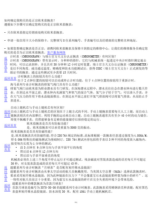
An OMEGA Te c h n o l o g ie s Co m p a n yMECHANICAL DIMENSIONS, mm (in)45+0.6 mm W x 22.2+0.3 mm H (1.772" x 0.874")MHD0496HAB5BDPM35A SeriesMiniature 1/32 DIN Process IndicatorFeatures a decimal point that can be set independently of signal range.For instance : 1 Vdc. signal on a ±2 Vdc meter can be displayed as 1.000, 10.00, 100.0, or 1000 for different engineering units. (in this example 1.000 V 10.00 mA.100.0% or 1000 mV)Fig.4a b c1 XX . X 1X . XX 1 . XX XDecimal pointposition Close Solder PadDisplay Board Components ViewDECIMAL POINT SELECTIONSignal Input Impedance ΩClose Jumpers0/4...20mA 182 1 & 20/10...50mA 68 1 & 30...2/10Vdc 200 K 10...10/200Vdc1 MNone*lower table, in function of signal input.Offset course : from -1000 to +1000To know the maximum negative Offset value, according to the Span value to be displayed apply this formula :((R3/S3) x S1) -1000.Span course for signal input :in Current, minimum 100 counts and maximum 3000 countsin Voltage, minimum 100 counts and maximum 2000 counts*Standard signal input for all orders unless specified otherwise.Display is adjusted to read 100.0WARRANTY/DISCLAIMEROMEGA warrants this unit to be free of defects in materials and workmanship and to give satisfactory service for a period of 13 months from date of purchase.OMEGA Warranty adds an additional one (1) month grace period to the normal one (1) year product warranty to cover handling and shipping time. This ensures that OMEGA's customers receive maximum coverage on each product. If the unit should malfunction, it must be returned to the factory for evaluation. OMEGA's Customer Service Department will issue an Authorized Return (AR)number immediately upon phone or written request. Upon examination by OMEGA, if the unit is found to be defective it will be repaired or replaced at no charge. However, this WARRANTY is VOID if the unit shows evidence of having been tampered with or shows evidence of being damaged as a result of excessive corrosion; or current; heat; moisture or vibration; improper specification; misapplication; misuse or other operating conditions outside of OMEGA's control. Components which wear or which are damaged by misuse are not warranted. These include contact points, fuses and triacs..OMEGA is pleased to offer suggestions on the use of its various products.However OMEGA neither assumes responsability for any omissions or errors nor assumes liability for any damages that result from the use of its products in accordance with information provided by OMEGA, either verbal or written.OMEGA only warrants that the parts manufactured by it will be as specified and free of defects. OMEGA MAKES NO OTHER WARRANTIES OR REPRE-SENTATIONS OF ANY KIND WHATSOEVER, EXPRESSED OR IMPLIED, EX-CEPT THAT OF TITLE AND ALL IMPLIED WARRANTIES INCLUDING ANY WARRANTY OF MERCHANTABILITY AND FITNESS FOR A PARTICULAR PUR-POSE ARE HEREBY DISCLAIMED.LIMITATION OF LIABILITY: The remedies of purchaser set forth herein are exclusive and the total liability of OMEGA with respect to this order, whether based on contract, warranty, negligence, indemnification, strict liability or otherwise, shall not exceed the purchase price of the component upon which liability is based. In no even shall OMEGA be liable for consequential,incidental or special damages.CONDITIONS: Equipment sold by OMEGA is not intended to be used, nor shall it be used:(1) as a "Basic Component" under 10 CFR 21 (NRC), used in or with any nuclear installation or activity; or (2) in medical applications or used on humans. Should any Product(s) be used in or with any nuclear installation or activity, medical application, used in humans, or misused in any way. OMEGA assumes no responsibility as set forth in our basic WARRANTY/DISCLAIMER language, and, additionally, purchaser will indemnify OMEGA and hold OMEGA harmlees from any liability or damage whatsoever arising out of the use of the Product(s) in such a manner.Servicing USA and Canada: Call OMEGA Toll FreeUSA CanadaOne Omega Drive, Box 4047976 BergarStamford, CT 06907-0047Laval (Quebec) H7L 5A1Telephone: (203) 359-1660Telephone: (514) 856-6928FAX: (203) 359-7700FAX: (514) 856-6886Sales Service: 1-800-826-6342 / 1-800-TC-OMEGA SM Customer Service: 1-800-622-2378 / 1-800-622-BEST SM Engineering Service: 1-800-872-9436 / 1-800-USA-WHEN SMTELEX: 996404 EASYLINK: 62968934 CABLE: OMEGAServicing Europe: One OMEGA Drive, River BendThecnology CentreNorthbank, Irlam, ManchesterM44 5EX , EnglandTelephone: 44 (161) 777-6611 FAX: 44 (161) 777-6622RETURN REQUESTS / INQUIRIESDirect all warranty and repair requests/inquiries to the OMEGA ENGINEERING Customer Service Department. BEFORE RETURNING ANY PRODUCT(S) TO OMEGA, PUR-CHASER MUST OBTAIN AN AUTHORIZED RETURN (AR) NUMBER FROM OMEGA'S CUSTOMER SERVICE DEPARTMENT (IN ORDER TO AVOID PROCESSING DELAYS).The assigned AR number should then be marked on the outside of the return package and on any correspondence.FOR WARRANTY RETURNS, please have the following information available BE-FORE contacting OMEGA:1.P.O. number under which the product was PURCHASED.2.Model and serial number of the product under warranty, and3.Repair instructions and/or specific problems relative to the product.FOR NON-WARRANTY REPAIRS, consult OMEGA for current repair charges. Have the following information available BEFORE contacting OMEGA:1.P.O. number to cover the COST of therepair,2.Model and serial number of product, and3.Repair instructions and/or specificproblems relative to the product.OMEGA's policy is to make running changes, not model changes, whenever an improve-ment is possible. This affords our customers the latest in technology and engineering.OMEGA is a registered trademark of OMEGA ENGINEERING, INC.© Copyright 1998 OMEGA ENGINEERING, INC. All rights reserved. This documentation may not be copied, photocopied, reproduced, translated, or reduced to any electronic medium or machine-readable form, in whole or in part, without prior written consent of OMEGA ENGINEERING, INC.ADJUSTMENT AND CALIBRATION PROCEDUREDetermine the lowest input (S1); highest input (S2); lowest reading (R1) and highest reading (R2).S3 = S2 - S1R3 = R2 - R11.-Select the Signal Input type installing the Jumpers according to Table2.2.-Connect a calibrator to the signal input terminals.3.-Power up the instrument with the appropriate power supply.4.-Adjust the calibrator until it generates 0 mA. or 0 Vdc.5.-Turn the "ZERO" trimmer (P1) until the display shows "0000".6.-Adjust the calibrator until it generates the S3 value (difference between the highest and lowest signal).7.-Turn the "SPAN" trimmer (P2) until the display shows the R3 value (difference between the highest and lowestreading).The adjustment procedure is finished, but if the lowest signal is different of 0 then follows with the next point.8.-Adjust the calibrator until it generates the low signal S1. (i.e. 4 mA).9.-Turn the "ZERO" trimmer (P1) until the display shows the lowest reading R1. The reading for lowest signalcan be modified as much times as wanted. The value of R3 will not be affected.10.-Close the jumper for the decimal point, according to the required decimals, see table 1.Example :Signal Input : 4...20 mA; Display Reading : 0...125.0Determine the value of S3 and R3.S3 = 20-4 = 16 mA R3 = 1250-0 = 12501.-Close Jumpers 1 &2.2.-Connect the calibrator and power up the instrument.3.-Adjust the calibrator at 0 mA and turn the trimmer P1 until the display shows "0000"4.-Adjust the calibrator at 16 mA and turn the trimmer P2 until the display shows "1250"5.-Adjust the calibrator at 4 mA and turn the trimmer P1 until the display shows "0000"6.-Close the Solder Pad "a".GENERAL CONSIDERATIONSINSTALLATIONPRECAUTIONS.- The installation and the future use of this unit must be done by suitable qualified personnel. The unit has not DC(mains) switch, neither internal protection fuse, it will be in operation as soon as power is connected. The installation mustincorporate an external mains switch with a protection fuse and also the necessary devices to protect the operator andthe process when using the unit to control a machine or process where injury to personnel or damage to equipment orprocess, may occur as a result of failure of the unit.SAFETY PRESCRIPTIONS.- The unit has been designed and tested under UNE 20553 rules and is delivered in good condition. This data sheet contains useful information for electrical connections. Do not make wiring signal changes or connections when power is applied to the unit. Make signal connections before power is applied and, is reconnection is required, disconnect the DC (mains)power before such wiring is attempted.Install the unit in a places with a good ventilation to avoid the excessive heating. And far from electrical noise source or magnetic field generators such as power relays, electrical motors, speed controls etc...The unit cannot be installed in open places. Do not use until the installation is finished.POWER SUPPLY.- The power supply must be connected to the adequate terminals (see the connection instructions). The characteristics of the power supply are showed on the side label. Please make sure that the unit is correctly connected to a power supply of the correct voltage and frequency.Do not use other power supply otherwise permanent damage may be caused to the unit. Do not connect the unit to power sources heavily loaded or to circuits which power loads in cycle ON-OFF or to circuits which power inductive loads.WARNING.- The power supply is dc voltage, be careful with the polarity indicated for each terminal.SIGNAL WIRING.- Certain considerations must be given when install the signal input wires. If the wires are longs can act like an antenna and introduce the electrical noise to the unit, therefore :Do not install the signal input wires in the same conduit with power lines, heaters, solenoids, SCR controls etc...and always far from these elements.SAFETY CONSIDERATIONSPRESCRIPTIONS.- Before starting any operation of adjustment, replacement, maintenance or repair, the unit must be disconnected from any kind of power supply.Keep the unit clean , to assure good functioning and performance.To prevent electrical or fire hazard, do not expose the unit to excessive moisture.Do not operate the unit in the presence of flammable gases or fumes, such an environment constitutes a definite safety hazard. The unit is designed to be mounted in a metal panel.If the unit shows signs of damage, or is not able to show the expected measures, or has been stored in a bad conditions or a protection failure can occur, then do not attempt to operate and keep the unit out of service.IN CASE OF FIRE1.- Disconnect the unit from the power supply.2.- Give the alarm according to the local rules.3.- Switch off all the air conditioning devices.4.- Attack the fire with carbonic snow, do not use water in any case.WARNING : In closed areas do not use systems with vaporized liquids.Signal Input :Lowest (S1) = 4 mAHighest (S2) =20 mAReading :Lowest (R1) =200Highest (R2) =1700S3 = S2 - S1 = 20 - 4 =16 mA R3 = R2 - R1= 1700 - 200 = 1500Signal Input 4...20 mAEXAMPLES OF ADJUSMENT AND CALIBRATION PROCEDUREA.- Without offsetSignal Input :Lowest (S1) =0 mAHighest (S2) =20 mAReading :Lowest (R1) =0Highest (R2) = 1700S3 = S2 - S1=20 - 0 = 20 mA R3 = R2 - R1=1700 - 0 = 17001700200020 mAD i s p l a yInput Signal Input 0...20 mA Display Reading 0 (1700)B.- With Negative OffsetSignal Input :Lowest (S1) = 4 mAHighest (S2) =20 mAReading :Lowest (R1) =0Highest (R2) =1700S3 = S2 - S1= 20 - 4 =16 mA R3 = R2 - R1= 1700 - 0 =1700Signal Input 4...20 mA Display Reading 0 (1700)C.- With Positive Offset。
OMEGA HHM598数字钳式表说明书

OMEGAHHM598 Digital Clamp-On MeterOMEGAnet On-Line Service Internet e-mail **************Servicing North America:USA: ISO 9001 Certified Canada:One Omega Drive, Box 4047976 Bergar Stamford, CT 06907-0047Laval (Quebec) H7L5A1 Tel: (203) 359-1660Tel: (514) 856-6928 FAX: (203)359-7700FAX: (514) 856-6886e-mail:**************e-mail:**************SAFETY INFORMATIONThe following safety information must be observed to insure maximum personal safety during the operation at this meter:1. Do not use the meter if the meter or test leads look damaged, or if you suspect that the meter is not operating properly.2. Use caution when working above 60V dc or 30V ac rms. Such voltages posea shock hazard.3. When Using the probes, keep your fingers behind the finger guards on the probes.4. Measuring voltage which exceeds the limits of the clampmeter may damage the meter and expose the operator to a shock hazard. Always recognize the meter voltage limits as stated on the front of the meter.5. If the equipment is used in a manner not specified by the manufacturer, the protection provided the equipment may be impaired.SPECIFICATIONSDisplay: 3½ digit liquid crystal display (LCD) with a maximum reading of 1999. Polarity: Automatic, positive implied, negative polarity indication. Overrange: (OL) or (-OL) is displayed.Zero: Automatic.Low battery indication: The "below the operating level.Measurement rate: 2.5 times per second, nominal.Operating Environment: 0°C to 40°C at < 70% relative humidity.Storage Temperature: -20°C to 60°C, 0 to 80% R.H. with battery removed from meter.Accuracy: Stated accuracy at 23°C ± 5°C, <75% relative humidity. Safety: According to EN61010-1 protection class II overvoltage category (CAT III 600V) pollution degree 2.Clamp jaw: According to EN61010-2-032 CAT IV 600V.Power: Single standard 9-volt battery.Battery life: 200 hours typical.Dimensions: 250mm (H) x 100mm (W) x 46mm (D).Weight: Approx. 380g including battery.Accessories: One pair test leads, 9V battery.DC VOLTSRanges: 600VAccuracy:±(0.5%rdg + 1dgt)Input impedance: 10M WOverload protection: 600VDC or AC rms AC VOLTS (50Hz - 500Hz)Ranges: 200V,600VAccuracy: ±(1.2%rdg + 4dgts)Input impedance: 10M WOverload protection: 600VDC or AC rms RESISTANCERanges: 2K W,200K WAccuracy:±(1.2%rdg + 1dgt)Open circuit volts: 0.3VdcOverload protection: 600VDC or AC rms FREQUENCY (Autoranging)Ranges: 2KHz,20KHzAccuracy:±(0.1%rdg + 3dgts) Sensitivity: 80Vrms minOverload protection: 600VDC or AC rmsCONTINUITYAudible indication: less than 30W on 2K W rangeOverload protection: 600VDC or AC rmsDIODE TESTTest current: 1.0mA±0.6mAAccuracy:±(6.0%rdg + 3dgts)Open circuit volts: 3.0Vdc typicalAudible indication: <30mVOverload protection: 600VDC or AC rmsAC CURRENT (Put conductor at the center of the jaws) Ranges: 20A,200A,700AAccuracy:50-60Hz ±(1.5%rdg + 4dgts)40-500Hz ±(3.5%rdg + 5dgts)*700A to 1000A(50Hz-60Hz): ±(2.0%rdg + 4dgts)Overload protection: 1000Aac max. for 1 minuteOPERATIONBefore taking any measurements, read the Safety Information Section. Always examine the instrument for damage, contamination (excessive dirt, grease, etc.) and defects. Examine the test leads for cracked or frayed insulation. If any abnormal conditions exist do not attempt to make any measurements.MAX HOLD Button:absolute reading). In the MAX Hold mode, the "" annunciator is displayed.Current and Hz ranges without MAX HOLD function.PEAK HOLD Button: (only current ranges 40-60Hz)Voltage Measurements1. Connect the red test lead to the "V" jack and the black test lead to the "COM" jack.2. Set the Function/Range switch to the desired Voltage type (AC or DC) and range. If magnitude of voltage is not known, set switch to the highest range and reduce until a satisfactory reading is obtained.3. Connect the test leads to the device or circuit being measured.4. For dc, a (-) sign is displayed for negative polarity, positive polarity is implied. Current Measurements1. Set the Function/Range switch to the highest 700A ac range.2. Press the trigger to open transformer jaws and clamp onto one conductor only. Read the current directly on the display. It is recommended that the conductor be placed at the center of the closed jaws for maximum accuracy.3. When the reading is lower than 200 counts, set the range switch to the next lower range position. For maximum accuracy, select the lower range possible without overranging the meter.Resistance Measurements1. Set the Function/Range switch to the desired resistance range.2. Remove power from the equipment under test.3. Connect the red test lead to the " + " jack and the black test lead to the "COM" jack.4. Touch the probes to the test points. In ohms, the value indicated in the display is the measured value of resistance.WARNINGThe accuracy of the functions might be slightly affected, when exposed to a radiated electromagnetic field environment, eg, radio, telephone or similar.Frequency Measurements1. Set the Function/Range switch to the Hz position.2. Connect the red test lead to the " + " jack and the black test lead to the "COM" jack.3. Connect the test leads to the point of measurement and read the frequency from the display.Continuity Measurements1. Set the Function/Range switch to the "2K W" position.2. Touch the probes to the test points. the beeper sounds continuously, if the resistance is less than 30W.Diode Tests1. Connect the red test lead to the " + " jack and the black test lead to the "COM" jack.2. Set the Function/Range switch to the "" position.3. Turn off power to the circuit under test.4. Touch probes to the diode. A forward-voltage drop is about 0.6V (typical fora silicon diode).5. Reverse probes. If the diode is good, "OL" is displayed. If the diode is shorted, ".000" or another number is displayed.6. If the diode is open, "OL" is displayed in both directions.7. If the junction is measured in a circuit and a low reading is obtained with both lead connections, the junction may be shunted by a resistance of less than 1k W. In this case the diode must be disconnected from the circuit for accurate testing.MAINTENANCEWARNINGRemove test leads before changing batteryor performing any servicing.Battery ReplacementPower is supplied by a 9 volt "transistor" battery. (NEDA 1604, IEC 6F22). The "" appears on the LCD display when replacement is needed. To replace the battery, remove the two screws from the back of the meter and lift off the battery cover. Remove the battery from battery contacts.CleaningPeriodically wipe the case with a damp cloth and detergent, do not use abrasives or solvents.9WARRANTY / DISCLAIMEROMEGA ENGINEERING, INC. warrants this unit to be free of defects in materials and workmanship for a period of 13 months from date of purchase. OMEGA Warranty adds an additional one (1) month grace period to the normal one (1) year product warranty to cover handling and shipping time. This ensures that OMEGA's customers receive maximum coverage on each product.If the unit should malfunction, it must be returned to the factory for evaluation. OMEGA's Customer Service Department will issue an Authorized Return (AR) number immediately upon phone or written request. Upon examination by OMEGA, if the unit is found to be defective it will be repaired or replaced at no charge. OMEGA's WARRANTY does not apply to defects resulting from any action of the purchaser, including but not limited to mishandling, improper interfacing, operation outside of design limits, improper repair, or unauthorized modification. This WARRANTY is VOID if the unit shows evidence of having been tampered with or shows evidence of being damaged as a result of excessive corrosion; or current, heat moisture or vibration; improper specification; misapplication; misuse or other operating conditions outside of OMEGA's control. Components which wear are not warranted, including but not limited to contact points, fuses, and triacs.OMEGA is pleased to offer suggestions on the use of its various products. However, OMEGA neither assumes responsibility for any omissions or errors nor assumes liability for any damages that result from the use of its products in accordance with information provided by OMEGA, either verbal or written. OMEGA warrants only that the parts manufactured by it will be as specified and free of defects. OMEGA MAKES NO OTHER WARRANTIES OR REPRESENTATIONS OF ANY KIND WHATSOEVER, EXPRESSED OR IMPLIED, EXCEPT THAT OF TITLE AND ALL IMPLIED WARRANTIES INCLUDING ANY WARRANTY OF MERCHANTABILITY AND FITNESS FOR A PARTICULAR PURPOSE ARE HEREBY DISCLAIMED. LIMITATION OF LIABILITY: The remedies of purchaser set forth herein are exclusive and the total liability of OMEGA with respect to this order, whether based on contract, warranty, negligence, indemnification, strict liability or otherwise, shall not exceed the purchase price of the component upon which liability is based. In no event shall OMEGA be liable for consequential, incidental or special damages.CONDITIONS: Equipment sold by OMEGA is not intended to be used, nor shall it be used: (1) as a "Basic Component" under 10 CFR 21 (NRC), used in or with any nuclear installation or activity; or (2) in medical applications or used on humans. Should any Product(s) be used in or with any nuclear installation or activity, medical application, used on humans, or misused in any way, OMEGA assumes no responsibility as set forth in our basic WARRANTY / DISCLAIMER language, and additionally, purchaser will indemnify OMEGA and hold OMEGA harmless from any liability or damage whatsoever arising out of the use of the Product(s) in such a manner.RETURN REQUESTS / INQUIRIESDirect all warranty and repair requests/inquiries to the OMEGA Customer Service Department. BEFORE RETURNING ANY PRODUCT(S) TO OMEGA, PURCHASER MUST OBT AIN AN AUTHORIZED RETURN (AR) NUMBER FROM OMEGA'S CUSTOMER SERVICE DEP ARTMENT (IN ORDER TO AVOID PROCESSING DELAYS). The assigned AR number should then be marked on the outside of the return package and on any correspondence.The purchaser is responsible for shipping charges, freight, insurance and proper packaging to prevent breakage in transit.FOR WARRANTY RETURNS, please have the following information available BEFORE contacting OMEGA:1.P.O. number under which the product was PURCHASED.2.Model and serial number of the product under warranty, and3.Repair instructions and/or specific problems relative to theproduct.FOR NON-WARRANTY REP AIRS, consult OMEGA for current repair charges. Have the following informationavailable BEFORE contacting OMEGA:1.P.O. number to cover the COST of the repair.2.Model and serial number of product , and3.Repair instructions and/or specific problems relative to theproduct.OMEGA's policy is to make running changes, not model changes, whenever an improvement is possible. This affords our customers the latest in technology and engineering. OMEGA is a registered trademark of OMEGA ENGINEERING, INC. © Copyright 1999 OMEGA ENGINEERING, INC. All rights reserved. This document may not be copied, photocopied, reproduced, translated, or reduced to any electronic medium or machine-readable from, in whole or in part, without prior written consent of OMEGA ENGINEERING, INC.Where Do I Find Everything I Need for Process Measurement and Control?OMEGA...Of Course!TEMPERATUREþThermocouple, RTD & Thermistor Probes, Connectors, Panels & Assemblies þWire: Thermocouple, RTD & Thermistor þCalibrators & Ice Point ReferencesþRecorders, Controllers & Process Monitors þInfrared PyrometersPRESSURE/STRAIN AND FORCEþTransducers & Strain GaugesþLoad Cells & Pressure GaugesþDisplacement TransducersþInstrumentation & AccessoriesFLOW/LEVELþRotameters, Gas Mass Flowmeters& Flow ComputersþAir Velocity IndicatorsþTurbine/Paddlewheel SystemsþTotalizers & Batch ControllerspH/CONDUCTIVITYþpH Electrodes, Testers & AccessoriesþBenchtop/Laboratory MetersþControllers, Calibrators, Simulators& PumpsþIndustrial pH & Conductivity Equipment DATA ACQUISITIONþData Acquisition &Engineering SoftwareþCommunications-Based Acquisition SystemsþPlug-in Cards for Apple, IBM& CompatiblesþDatalogging SystemsþRecorders, Printers & Plotters HEATERSþHeating CableþCartridge & Strip HeatersþImmersion & Band HeatersþFlexible HeatersþLaboratory Heaters ENVIRONMENTAL MONITORING AND CONTROL þMetering & Control Instrumentation þRefractometersþPumps & TubingþAir, Soil & Water MonitorsþIndustrial Water & Wastewater TreatmentþpH, Conductivity & Dissolved Oxygen InstrumentsM-2879/0799。
Omega DPF20系列面板表面仪表说明书

Panel Meter for Frequency, Rate, Total or Period Counter6-Digit, 1⁄8 DIN Panel MountDPF20 SeriesU D ual Channel(A + B + Reset)U O ption for WallMountingU N EMA 4 (IP65)Front PanelU P ower Options of85 to 260 Vac and11 to 60 VdcU E xcitation PowerSupply of 5 to 18 Vdc@ 70 mAU O ptional Outputs:Modbus®, Up to6 Relays, Analog,SSR Drive, RS485and RS232ApplicationsU I ndustrial Flow Rate or Total Indication andAlarm or ControlU A ngular Position orRPM Indication (withQuadrature Sensor)U P roduct/Piece Counting or Production RateIndicationOmega’s new DPF20 Series of indicators offer real flexibility for measurement of a wide range of frequency or pulse inputs. The display is easily configured to indicate frequency, rate, periodor count. This makes the meter ideal for flow applications where they can display flow rate or total from a variety of different flow sensors. Or for quadrature signals, to indicate angular position or rotational speed and direction. The DPF20 series offers exceptional performance at an economical price, with some unique and powerful features, summarized in the table onpage 3.SpecificationsMain Functions: Counter,ratemeter, period meterDisplay Digits: 6Display Range: 999999/-199999Decimal Point: ConfigurableLED Color: Red standard;green optionalDigit Height: 14 mm (0.55")Signals Accepted: NPN, PNP,Namur, pick-up, TTL, inductive,mechanical, quadratureExcitation Voltage: 5 Vdc, 9 Vdc,15 Vdc, 18 Vdc (max. 70 mA)Maximum Vdc at Input Terminals:±30 VdcInput Impedance: 2.4 kΩ withpull-up or pull-down resistor; 470 kwithout resistorQuartz Accuracy: ±0.01%Thermal Stability: 20 ppm/ºCDisplay Refresh: 15/secondMaximum Frequencies:Counter: Up to 250 KHzR atemeter and Period Meter: Upto 500 KHzMinimum Frequencies: Down to1 mHz (0.001 Hz) (ratemeter andperiod meter)Standard Power: 85 to 265 Vac/DC(isolated 2,500 Vac)Low Power: 11 to 60 Vdc and 24/48Vac (isolated 1500 Vac)Power Consumption: <1.5 W (meteronly); < 4.0 W (meter with options)Connections: Plug-in screw terminalSlow Function: For low frequencyrate meter applicationsFast Function: For high frequencycounter applicationsScaling Factor: Multiplier and dividerfrom 1 to 999999Configurable Reset: Front panel andrear remote reset, and reset linked toalarm activationPreset: ConfigurableRetention Memory: Recovers countvalue in case of power lossDimensions andEnvironmentWeight: <150 grams (<5.3 oz)Front Panel Size: 96 x 48 mm(3.78 x 1.89")Panel Cut-Out: 92 x 44 mm(3.62 x 1.73")Depth Behind Panel: 91 mm (3.58")including terminalsOperating Temperature: 0 to 50ºC(32 to 122ºF)Storage Temperature: -20 to 70ºC(-4 to 158ºF)Warm Up: 15 minutesFront Panel Protection: NEMA 4(IP65)DPF20-LV shown actual size.Output and Communications Options (Up to 3 slots, field installable)To order with plain front lens (no operator access to buttons) add suffix “-NBT” to meter model number. Contact sales for pricing. Comes with unit of measurement stickers, panel mounting clips, and installation/operator’s manual.Order Example: DPF20-LV-GN-NBT, 6-digit frequency panel meter, 11 to 60 Vdc powered, with green display and plain front lens.。
欧米加数字多功能表计说明书

OMEGAHHM17Digital MultimeterOMEGAnet On-Line Service Internet e-mail **************Servicing North America:USA: ISO 9001 Certified Canada:One Omega Drive, Box 4047976 Bergar Stamford, CT 06907-0047Laval (Quebec) H7L5A1 Tel: (203) 359-1660Tel: (514) 856-6928 FAX: (203)359-7700FAX: (514) 856-6886e-mail:**************e-mail:**************SAFETY INFORMATIONThe following safety information must be observed to insure maximum personal safety during the operation at this meter:1. Do not use the meter if the meter or test leads look damaged, or if you suspect that the meter is not operating properly.2. This meter is not recommended for high voltage industrial use; for example, not for measurements of 440 VAC or 600 VAC industrial power mains. The unit is intended for use with low energy circuits to 600VDC or AC or high energy circuit to 250 VAC or DC. Accidental misuse by connection across a high voltage, high energy power source when the meter is set up for mA measurement may be very hazardous.3. Turn off power to the circuit under test before cutting, unsoldering, or breaking the circuit. Small amounts of current can be dangerous.4. Use caution when working above 60V dc or 30V ac rms. Such voltages posea shock hazard.5. When Using the probes, keep your fingers behind the finger guards on the probes.6. Measuring voltage which exceeds the limits of the multimeter may damage the meter and expose the operator to a shock hazard. Always recognize the meter voltage limits as stated on the front of the meter.7. If the equipment is used in a manner not specified by the manufacturer, the protection provided the equipment may be impaired.SPECIFICATIONSDisplay: 3¾ digit (4000 counts), 9999counts (Frequency mode), 40 segments analog bar graph and function units sign annunciators.Polarity: Automatic, positive implied, negative polarity indication. Overrange: "4000"or"-4000" Most Significant Digit blinks.Low battery indication: the "" is displayed when the battery voltage drops below the operating level.Measurement rate: 2/sec,nominal. 1/sec, Capacitance and Frequency mode. 20/sec, Analog display.Operating Environment: 0°C to 40°C at < 70% relative humidity.Storage Temperature: -20°C to 60°C, 0 to 80% R.H. with battery removed from meter.Accuracy: Stated accuracy at 23°C ± 5°C, <75% relative humidity. Safety: According to EN61010-1 protection class II overvoltage category (CAT II 600V) pollution degree 2.Auto Power off: 30minutes after rotary switch or mode changes. Power: single standard 9-volt battery.Battery life: 200 hours typical.Dimensions: 192mm (H) x 91mm (W) x 52.5mm (D).Weight: Approx. 365g including battery.Accessories: One pair test leads, One spare fuse installed, 9V battery and Operating Instructions.DC VOLTSRanges: 400mV,4V,40V,400V,600VResolution: 100µVAccuracy:±(0.25%rdg + 1dgt) on 400mV to 400V ranges±(0.25%rdg + 3dgts) on 600V rangeInput impedance: >10M WOverload protection: 600VDC or AC rmsAC VOLTSRanges: 400mV,4V,40V,400V,600V (400mV only Manual @50Hz-100Hz)Resolution: 100µVAccuracy:Input impedance: >10M WOverload protection: 600VDC or AC rms Range100Hz 1KHz 10KHz 20KHz400mV4V40V400V600V ±(0.75%rdg+5dgts)±(0.75%rdg+5dgts)N/A ±(1.5%rdg+4dgts)±(2.0%rdg+30dgts)N/ADC CURRENTRanges: 4mA,40mA,400mA,10AAccuracy:±(0.5%rdg + 1dgt) on mA ranges±(2.0%rdg + 1dgt) on 10A rangeInput protection:0.5A / 250V fast blow ceramic fuse10A / 600V fast blow ceramic fuse AC CURRENT (50Hz - 500Hz)Ranges: 4mA,40mA,400mA,10AAccuracy:±(1.0%rdg + 4dgts) on mA ranges±(3.0%rdg + 4dgts) on 10A rangeInput protection:0.5A / 250V fast blow ceramic fuse10A / 600V fast blow ceramic fuse RESISTANCERanges: 400W,4K W,40K W,400K W,4M W ,40M W Accuracy:±(0.3%rdg + 4dgts) on 400W range±(0.3%rdg + 1dgt) on 4K W to 4M W ranges±(1.0%rdg + 4dgts) on 40M W range Open circuit volts: 0.4VdcOverload protection: 500VDC or AC rms CONTINUITYAudible indication: less than 40W±20WOverload protection: 500VDC or AC rmsDIODE TESTTest current: 1.0mA±0.6mAAccuracy:±(3.0%rdg + 3dgts)Open circuit volts: 3.0Vdc typicalOverload protection: 500VDC or AC rms CAPACITANCERanges: 4nF,40nF,400nF,4µF,40µFAccuracy:±(2.0%rdg+20dgts) on 4n Frange(use 0ADJ)±(2.0%rdg + 4dgts) on 40nF to 40µF ranges±(5.0%rdg + 4dgts) above 40µFOverload protection: 500VDC or AC rms FREQUENCY (Autoranging)Ranges: 100Hz,1KHz,10KHz,100KHz,700KHz Resolution: 0.01HzAccuracy:±(0.05%rdg + 2dgts)Sensitivity: 1.0V rms minOverload protection: 500VDC or AC rms TRANSISTOR hFERanges: 0 - 1000Base current: 10µAdc approx. (Vce=3.0Vdc)OPERATIONBefore taking any measurements, read the Safety Information Section. Always examine the instrument for damage, contamination (excessive dirt, grease, etc.) and defects. Examine the test leads for cracked or frayed insulation. If any abnormal conditions exist do not attempt to make any measurements.PON ButtonWhen the meter is automatic power-off, press the button to turns meter back on.Note: Disable Automatic Power-offIf you press and hold down the (PON) button while turning the meter from OFF to on and select a function, the automatic power-off feature is disabled. MEM ButtonWhen (MEM) button is pressed, the "MEM" annunciator is displayed and the last reading is stored on the meter. If the meter power down automatically and the power back on by pressing (PON) button, these stored readings will remain in memory.READ ButtonPress (READ) Button to recall the data you stored in memory, the readings will be displayed on the LCD, the "HOLD"annunciator turn on,and the "MEM" annunciator will be displayed with a blink. The automatic power-off feature is disabled. Press (HOLD) button to exit the READ mode.Press (REL) button to enter the Relative mode, the "REL D" annunciator turn on, zero the display, and store the displayed reading as a reference value. Press and hold down the (REL) button for 2 seconds to exit the relative mode. MIN / MAX buttonPress (MIN / MAX) button to enter the MIN MAX Recording mode. The minimum, maximum values are then reset to the present input, the readings are stored in memory, and the "HOLD" annunciator turns on. Push the button to cycle through the minimum (MIN), maximum (MAX), and present readings. The MIN or MAX annunciator turns on to indicate what value is being displayed.In the MIN MAX Recording mode, press (HOLD) button to stop the recording of readings, press again to restart recording. If recording is stopped, the minimum, maximum, or present values and analog diaplay are frozen. In the MIN MAX Recording mode, when a new minimum value is exceed the actual minimum readings or a new maximum value is overload, the minimum or maximum value will held on the display, but the analog display continues to be active.Press (HOLD) button to toggle in and out of the Data Hold mode, except if you are already in the MIN MAX Recording mode.In the Data Hold mode, the "HOLD" annunciator is displayed and the last reading is held on the display, the beeper emits a tone, and the automatic power-off feature is disable. Pressing (MIN / MAX) button when you are in the Data Hold mode causes you to exit Data Hold and enter the MIN MAX Recording mode.In the MIN MAX Recording mode, press (HOLD) button to stop the recording of readings, press (HOLD) again to resume recording.RANGE ButtonPress (RANGE) button to select the Manual Range mode and turn off the "AUTO" annunciator. (The meter remains in the range it was in when manual ranging was selected).In the Manual Range mode. each time you press (RANGE) button, the range (and the input range annunciator) increments, and a new value is displayed. To exit the Manual Range mode and return to autoranging, press and hold down (RANGE) button for 2 seconds. The "AUTO" annunciator turns back on.Alternate Function ButtonThe Alternate Function button is Blue in color. Press it to toggle to the alternate function (AC, Audible continuity and Capacitance) shown in Blue on the meter face.Voltage Measurements1. Connect the red test lead to the "V W" jack and the black test lead to the "COM" jack.2. Set the Function/Range switch to the desired voltage range and press the Blue toggle button to select AC or DC. The meter will automatically select the best voltage range.3. Connect the test leads to the device or circuit being measured.4. For dc, a (-) sign is displayed for negative polarity; positive polarity is implied. Current Measurements1. Set the Function/Range switch to the desired current range and press the Blue toggle button to select AC or DC.2. For current measurements less than 400mA, connect the red test lead to the mA jack and the black test lead to the COM jack.3. For current measurements of 400mA or greater, connect the red test lead to the 10A jack and the black test lead to the COM jack.4. Remove power from the circuit under test and open the normal circuit path where the measurement is to be taken. Connect the meter in series with the circuit.5. Use caution when measuring 10 amps on 10A range for 60s, please waiting for 10 minutes for next measurement of 10 amps for safety reason.Resistance and Continuity Measurements1. Set the Function/Range switch to the desired resistance range or continuity position.2. Remove power from the equipment under test.3. Connect the red test lead to the "V W" jack and the black test lead to the "COM" jack.4. Touch the probes to the test points. In ohms, the value indicated in the display is the measured value of resistance.5. Press the Blue Alternate Function button to select Audible Continuity.In continuity test, the beeper sounds continuously, if the resistance is less than 40W.WARNINGThe accuracy of the functions might be slightly affected, when exposed to a radiated electromagnetic field environment, eg, radio, telephone or similar.Diode Tests1. Connect the red test lead to the "V W" jack and the black test lead to the "COM" jack.2. Set the Function/Range switch to the "3. Turn off power to the circuit under test.4. Touch probes to the diode. A forward-voltage drop is about 0.6V (typical fora silicon diode).5. Reverse probes. If the diode is good, display will be between 2.800V and 3.200V. If the diode is shorted, ".000" or another number is displayed.6. If the diode is open, display will be between 2.800V and 3.200V, in both directions.7. If the junction is measured in a circuit and a low reading is obtained with both lead connections, the junction may be shunted by a resistance of less than 1k W. In this case the diode must be disconnected from the circuit for accurate testing.Capacitance Measurements1. Set the Function/Range switch to the desired "" range and press the Blue toggle button to select Cx.2. Never apply an external voltage to the Cx sockets. Damage to the meter may result.3. Insert the capacitor leads directly into the Cx socket.4. Read the capacitance directly from the display.Transistor Gain Measurements1. Set the Function/Range switch to the desired hFE range (PNP or NPN type transistor).2. Never apply an external voltage to the hFE sockets. Damage to the meter may result.3. Plug the transistor directly into the hFE socket. The sockets are labeled E,B andC for emitter, base, and collector.4. Read the transistor hFE (dc gain) directly from the display.Frequency Measurements1. Set the Function/Range switch to the Hz position.2. Connect the red test lead to the "V W" jack and the black test lead to the "COM" jack.3. Connect the test leads to the point of measurement and read the frequency from the display.MAINTENANCEWARNINGRemove test leads before changing battery or fuseor performing any servicing.Battery ReplacementPower is supplied by a 9 volt "transistor" battery. (NEDA 1604, IEC 6F22). The "" appears on the LCD display when replacement is needed. To replace the battery, remove the two screws from the back of the meter and lift off the battery case. Remove the battery from battery contacts.Fuse ReplacementIf no current measurements are possible, check for a blown overload protec-tion fuse. There are two fuses; F1 for the "mA" jack and F2 for the "10A" jack. For access to fuses, remove the four screws from the back of the meter and lift off the battery cover and case. Replace F1 only with the original type 0.5A/ 250V, fast acting ceramic fuse. Replace F2 only with the original type 10A/ 600V, fast acting ceramic fuse.CleaningPeriodically wipe the case with a damp cloth and detergent, do not use abrasives or solvents.WARRANTY / DISCLAIMEROMEGA ENGINEERING, INC. warrants this unit to be free of defects in materials and workmanship for a period of 13 months from date of purchase. OMEGA Warranty adds an additional one (1) month grace period to the normal one (1) year product warranty to cover handling and shipping time. This ensures that OMEGA's customers receive maximum coverage on each product.If the unit should malfunction, it must be returned to the factory for evaluation. OMEGA's Customer Service Department will issue an Authorized Return (AR) number immediately upon phone or written request. Upon examination by OMEGA, if the unit is found to be defective it will be repaired or replaced at no charge. OMEGA's WARRANTY does not apply to defects resulting from any action of the purchaser, including but not limited to mishandling, improper interfacing, operation outside of design limits, improper repair, or unauthorized modification. This WARRANTY is VOID if the unit shows evidence of having been tampered with or shows evidence of being damaged as a result of excessive corrosion; or current, heat moisture or vibration; improper specification; misapplication; misuse or other operating conditions outside of OMEGA's control. Components which wear are not warranted, including but not limited to contact points, fuses, and triacs.OMEGA is pleased to offer suggestions on the use of its various products. However, OMEGA neither assumes responsibility for any omissions or errors nor assumes liability for any damages that result from the use of its products in accordance with information provided by OMEGA, either verbal or written. OMEGA warrants only that the parts manufactured by it will be as specified and free of defects. OMEGA MAKES NO OTHER WARRANTIES OR REPRESENTATIONS OF ANY KIND WHATSOEVER, EXPRESSED OR IMPLIED, EXCEPT THAT OF TITLE AND ALL IMPLIED WARRANTIES INCLUDING ANY WARRANTY OF MERCHANTABILITY AND FITNESS FOR A PARTICULAR PURPOSE ARE HEREBY DISCLAIMED. LIMITATION OF LIABILITY: The remedies of purchaser set forth herein are exclusive and the total liability of OMEGA with respect to this order, whether based on contract, warranty, negligence, indemnification, strict liability or otherwise, shall not exceed the purchase price of the component upon which liability is based. In no event shall OMEGA be liable for consequential, incidental or special damages.CONDITIONS: Equipment sold by OMEGA is not intended to be used, nor shall it be used: (1) as a "Basic Component" under 10 CFR 21 (NRC), used in or with any nuclear installation or activity; or (2) in medical applications or used on humans. Should any Product(s) be used in or with any nuclear installation or activity, medical application, used on humans, or misused in any way, OMEGA assumes no responsibility as set forth in our basic WARRANTY / DISCLAIMER language, and additionally, purchaser will indemnify OMEGA and hold OMEGA harmless from any liability or damage whatsoever arising out of the use of the Product(s) in such a manner.RETURN REQUESTS / INQUIRIESDirect all warranty and repair requests/inquiries to the OMEGA Customer Service Department. BEFORE RETURNING ANY PRODUCT(S) TO OMEGA, PURCHASER MUST OBT AIN AN AUTHORIZED RETURN (AR) NUMBER FROM OMEGA'S CUSTOMER SERVICE DEP ARTMENT (IN ORDER TO AVOID PROCESSING DELAYS). The assigned AR number should then be marked on the outside of the return package and on any correspondence.The purchaser is responsible for shipping charges, freight, insurance and proper packaging to prevent breakage in transit.FOR WARRANTY RETURNS, please have the following information available BEFORE contacting OMEGA:1.P.O. number under which the product was PURCHASED.2.Model and serial number of the product under warranty, and3.Repair instructions and/or specific problems relative to theproduct.FOR NON-WARRANTY REPAIRS, consult OMEGA for current repair charges. Have the following informationavailable BEFORE contacting OMEGA:1.P.O. number to cover the COST of the repair.2.Model and serial number of product , and3.Repair instructions and/or specific problems relative to theproduct.OMEGA's policy is to make running changes, not model changes, whenever an improvement is possible. This affords our customers the latest in technology and engineering. OMEGA is a registered trademark of OMEGA ENGINEERING, INC. © Copyright 1999 OMEGA ENGINEERING,Where Do I Find Everything I Need for Process Measurement and Control?OMEGA...Of Course!TEMPERATUREþThermocouple, RTD & Thermistor Probes, Connectors, Panels & Assemblies þWire: Thermocouple, RTD & Thermistor þCalibrators & Ice Point ReferencesþRecorders, Controllers & Process Monitors þInfrared PyrometersPRESSURE/STRAIN AND FORCEþTransducers & Strain GaugesþLoad Cells & Pressure GaugesþDisplacement TransducersþInstrumentation & AccessoriesFLOW/LEVELþRotameters, Gas Mass Flowmeters& Flow ComputersþAir Velocity IndicatorsþTurbine/Paddlewheel SystemsþTotalizers & Batch ControllerspH/CONDUCTIVITYþpH Electrodes, Testers & AccessoriesþBenchtop/Laboratory MetersþControllers, Calibrators, Simulators& PumpsþIndustrial pH & Conductivity Equipment DATA ACQUISITIONþData Acquisition &Engineering SoftwareþCommunications-Based Acquisition SystemsþPlug-in Cards for Apple, IBM& CompatiblesþDatalogging SystemsþRecorders, Printers & Plotters HEATERSþHeating CableþCartridge & Strip HeatersþImmersion & Band HeatersþFlexible HeatersþLaboratory Heaters ENVIRONMENTAL MONITORING AND CONTROL þMetering & Control Instrumentation þRefractometersþPumps & TubingþAir, Soil & Water MonitorsþIndustrial Water & Wastewater TreatmentþpH, Conductivity & Dissolved Oxygen Instruments。
Omega Platinum 36 MM 铂金表带说明书

DP32Pt, D P16Pt, D P8Pt温度和过程仪表本文档中所含的信息正确可信,但是 O MEGA 对于其中包含的任何错误不承担任何责任,并保留修改规格的权利,恕不另行通知。
目录1. 简介 (6)1.1 (6)1.2 注意 项 (7)1.3 接线说明 (8)1.3.1 连 (8)1.3.2 连 电 (9)1.3.3 连接输入 (9)1.3.4 带报警继电器的装置上的连 输 (11)2. 导航 (11)2.1 按钮动作说明 (11)2.2 菜单结构 (11)2.3 1 级菜单 (12)2.4 菜单循环流 (12)3. 完整菜单结构 (12)3.1 初始化模式菜单 (INIt) (12)3.2 编程模式菜单 (PRoG) (16)3.3 运行模式菜单 (oPER) (17)4. 参考章节:初始化模式 (INIt) (18)4.1 输入配置 (INIt > I NPt) (18)4.1.1 热电偶输入类型 (INIt > I NPt > t.C.) (18)4.1.2 电阻式温度检测器 (RTD) 输入类型 (INIt > I NPt > R td) (19)4.1.3 热敏电阻输入类型配置 (INIt > I NPt > t HRM) (20)4.1.4 过程输入类型配置 (INIt > I NPt > P RoC) (20)4.2 显示读数格式 (INIt > R dG) (21)4.2.1 小数点格式 (INIt > R dG > d EC.P) (21)4.2.2 温度单位 (INIt > R dG > °F°C) (21)4.2.3 滤波器 (INIt > R dG > F LtR) (22)4.2.4 标准色 (INIt > R dG > N CLR) (22)4.2.5 亮度 (INIt > R dG > b RGt) (22)4.3 激励电压 (INIt > E CtN) (22)4.4 通讯 (INIt > C oMM) (23)4.4.1 协议 (INIt > C oMM > U Sb, E tHN, S ER > P Rot) (23)4.4.2 地址 (INIt > C oMM > U Sb, E tHN, S ER > A ddR) (24)4.4.3 串行通讯参数 (INIt > C oMM > S ER >C.PAR) (24)4.5 安全功能 (INIt > S Fty) (26)4.5.1 通电确认 (INIt > S Fty > P woN) (26)4.5.2 运行模式确认 (INIt > S Fty > o PER) (26)4.5.3 设定值限值 (INIt > S Fty > S P.LM) (26)4.5.4 回路断开超时 (INIt > S Fty > L Pbk) (26)4.5.5 开路 (INIt > S Fty > o.CRk) (27)4.6 手动温度校准 (INIt > t.CAL) (27)4.6.1 动温 调 (INIt > t.CAL > N oNE) (27)4.6.2 手动温度校准偏差调整 (INIt > t.CAL > 1.PNt) (27)4.6.3 手动温度校准偏差和斜率调整 (INIt > t.CAL > 2.PNt) (27)4.6.4 温度冰点校准 (INIt > t.CAL > I CE.P) (28)4.7 将所有参数的当前配置保存在一个文件中 (INIt > S AVE) (28)4.8 加载文件中所有参数的配置 (INIt > L oAd) (28)4.9 显示固件修订编号 (INIt > V ER.N) (28)4.10 更新固件修订 (INIt > V ER.U) (28)4.11 重置为出厂默认参数 (INIt > F.dFt) (28)4.12 密码保护初始化模式访问 (INIt > I.Pwd) (29)4.13 密码保护编程模式访问 (INIt > P.Pwd) (29)5. 参考章节:编程模式 (PRoG) (29)5.1 设定值 1 配置 (PRoG > S P1) (29)5.2 设定值 2 配置 (PRoG > S P2) (29)5.3 报警模式配置 (PRoG > A LM.1, A LM.2) (30)5.3.1 报警类型 (PRoG > A LM.1, A LM.2 > t yPE) (30)5.3.2 绝对或偏差报警 (PRoG > A LM.1, A LM.2 > t yPE > A b.dV) (31)5.3.3 报警上限参考值 (PRoG > A LM.1, A LM.2 > t yPE > A LR.H) (31)5.3.4 报警下限参考值 (PRoG > A LM.1, A LM.2 > t yPE > A LR.L) (31)5.3.5 报 颜 (PRoG > A LM.1, A LM.2 > A.CLR) (32)5.3.6 报警高高/低低偏差值 (PRoG > A LM.1, A LM.2 > H I.HI) (32)5.3.7 报警锁定 (PRoG > A LM.1, A LM.2 > L tCH) (32)5.3.8 报 开 闭 (PRoG > A LM.1, A LM.2 > C tCL) (33)5.3.9 报警通电行为 (PRoG > A LM.1, A LM.2 > A.P.oN) (33)5.3.10 报警开启延迟 (PRoG > A LM.1, A LM.2 > d E.oN) (33)5.3.11 报警关闭延迟 (PRoG > A LM.1, A LM.2 > d E.oF) (33)5.4 输出通道配置 (PRoG > d tR1 或 P RoG > d tR2) (33)5.4.1 输出通道模式 (PRoG > d tR1, d tR2 > M odE) (33)6. 参考章节:运行模式 (oPER) (34)6.1 正常运行模式 (oPER > R UN) (34)6.2 更改设定值 1 (oPER > S P1) (34)6.3 更改设定值 2 (oPER > S P2) (35)6.4 清除锁定报警 (oPER > L.RSt) (35)6.5 显示最低读数 (oPER > V ALy) (35)6.6 显示最高读数 (oPER > P EAk) (35)6.7 待机模式 (oPER > S tby) (35)7. 规格 (36)7.1 输入 (36)7.2 输出(带“-‐AL” 配置,可选) (36)7.3 通讯(标配 U SB, 可选串行和以太网) (36)7.4 隔离 (36)7.5 常规 (37)8. 认证信息 (39)1.简介1.1本手册的第 1 节将介绍后面板连接和接线说明。
Omega 产品说明书.pdf_1718753297.219075

MQS5058/0113e-mail:**************For latest product manuals:W A R R A N T Y /D I S C L A I M E RO M E G A E N G I N E E R I N G , I N C ., w a r r e n t s t h i s u n i t t o b e f r e e o f d e f e c t s i n m a t e r i a l s a n d w o r k m a n s h i p f o r a p e r i o d o f 13 m o n t h s f r o m d a t e o f p u r c h a s e . O M E G A ’s W A R R A N T Y a d d s a n a d d i t i o n a l o n e (1) m o n t h g r a c e p e r i o d t o t h e n o r m a l o n e (1) y e a r p r o d u c t w a r r a n t y t o c o v e r h a n d l i n g a n d s h i p p i n g t i m e . T h i s e n s u r e s t h a t O M E G A ’s c u s t o m e r sr e c e i v e m a x i m u m c o v e r a g e o n e a c h p r o d u c t .I f t h e u n i t m a l f u n c t i o n s , i t m u s t b e r e t u r n e d t o t h e f a c t o r y f o r e v a l u a t i o n . O M E G A ’s C u s t o m e r S e r v i c e D e p a r t m e n t w i l l i s s u e a n A u t h o r i z e d R e t u r n (A R ) n u m b e r i m m e d i a t e l y u p o n p h o n e o r w r i t t e n r e q u e s t . U p o n e x a m i n a t i o n b y O M E G A , i f t h e u n i t i s f o u n d t o b e d e f e c t i v e , i t w i l l b e r e p a i r e d o r r e p l a c e d a t n o c h a r g e . O M E G A ’s W A R R A N T Y d o e s n o t a p p l y t o d e f e c t s r e s u l t i n g f r o m a n y a c t i o n o f t h e p u r c h a s e r , i n c l u d i n g b u t n o t l i m i t e d t o m i s h a n d l i n g , i m p r o p e r i n t e r f a c i n g , o p e r a t i o n o u t s i d e o f d e s i g n l i m i t s , i m p r o p e r r e p a i r , o r u n a u t h o r i z e d m o d i fi c a t i o n . T h i s W A R R A N T Y i s V O I D i f t h e u n i t s h o w s e v i d e n c e o f h a v i n g b e e n t a m p e r e d w i t h o r s h o w s e v i d e n c e o f h a v i n g b e e n d a m a g e d a s a r e s u l t o f e x c e s s i v e c o r r o s i o n ; o r c u r r e n t , h e a t , m o i s t u r e o r v i b r a t i o n ; i m p r o p e r s p e c i fi c a t i o n ; m i s a p p l i c a t i o n ; m i s u s e o r o t h e r o p e r a t i n g c o n d i t i o n s o u t s i d e o f O M E G A ’s c o n t r o l . C o m p o n e n t s i n w h i c hw e a r i s n o t w a r r a n t e d , i n c l u d e b u t a r e n o t l i m i t e d t o c o n t a c t p o i n t s , f u s e s , a n d t r i a c s .O M E G A i s p l e a s e d t o o f f e r s u g g e s t i o n s o n t h e u s e o f i t s v a r i o u s p r o d u c t s . H o w e v e r , O M E G A n e i t h e r a s s u m e s r e s p o n s i b i l i t y f o r a n y o m i s s i o n s o r e r r o r s n o r a s s u m e s l i a b i l i t y f o r a n y d a m a g e s t h a t r e s u l t f r o m t h e u s e o f i t s p r o d u c t s i n a c c o r d a n c e w i t h i n f o r m a t i o n p r o v i d e d b y O M E G A , e i t h e r v e r b a l o r w r i t t e n . O M E G A w a r r a n t s o n l y t h a t t h e p a r t s m a n u f a c t u r e d b y t h e c o m p a n y w i l l b e a s s p e c i fi e d a n d f r e e o f d e f e c t s . O M E G A M A K E S N O O T H E R W A R R A N T I E S O R R E P R E S E N T A T I O N S O F A N Y K I N D W H A T S O E V E R , E X P R E S S E D O R I M P L I E D , E X C E P T T H A T O F T I T L E , A N D A L L I M P L I E D W A R R A N T I E S I N C L U D I N G A N Y W A R R A N T Y O F M E R C H A N T A B I L I T Y A N D F I T N E S S F O R A P A R T I C U L A R P U R P O S E A R E H E R E B Y D I S C LA I M E D . L I M I T A T I O N O F L I AB I L I T Y : T h e r e m e d i e s o f p u r c h a s e r s e t f o r t h h e r e i n a r e e x c l u s i v e , a n d t h e t o t a l l i a b i l i t y o f O M E G A w i t h r e s p e c t t o t h i s o r d e r , w h e t h e r b a s e d o n c o n t r a c t , w a r r a n t y , n e g l i g e n c e , i n d e m n i fi c a t i o n , s t r i c t l i a b i l i t y o r o t h e r w i s e , s h a l l n o t e x c e e d t h e p u r c h a s e p r i c e o f t h e c o m p o n e n t u p o n w h i c h l i a b i l i t y i s b a s e d . I n n oe v e n t s h a l l O M E G A b e l i a b l ef o r c o n s e q u e n t i a l , i n c i d e n t a l o r s p e c i a l d a m ag e s .C O ND I T I O N S :E q u i p m e n t s o l d b y O M E G A i s n o t i n t e n d e d t o b e u s e d , n o r s h a l l i t b e u s e d : (1) a s a “B a s i c C o m p o n e n t ” u n d e r 10 CF R 21 (N R C ), u s e d i n o r w i t h a n y n u c l e a r i n s t a l l a t i o n o r a c t i v i t y ; o r (2) i n m e d i c a l a p p l i c a t i o n s o r u s e d o n h u m a n s . S h o u l d a n y P r o d u c t (s ) b e u s e d i n o r w i t h a n y n u c l e a r i n s t a l l a t i o n o r a c t i v i t y , m e d i c a l a p p l i c a t i o n , u s e d o n h u m a n s , o r m i s u s e d i n a n y w a y , O M EG A a s s u m e s n o r e s p o n s i b i l i t y a s s e t f o r t h i n o u r b a s i c W A R R A N T Y /D I S C L A I M E R l a n g u a g e , a n d , a d d i t i o n a l l y , p u r c h a s e r w i l l i n d e m n i f y O M E G A a n d h o l d O M E G A h a r m l e s s f r o m a n y l i a b i l i t y o r d a m a g e w h a t s o e v e r a r i s i n g o u to f t h e u s e o f t h e P r o d u c t (s ) i n s u c h a m a n n e r .R E T U R N R E Q U E S T S /I N Q U I R I E SD i r e c t a l l w a r r a n t y a n d r e p a i r r e q u e s t s /i n q u i r i e s t o t h e O ME G A C u s t o m e r S e r v i c eD e p a r t m e n t . BEF O R E R E T U R N I NG A N Y P R O D U C T (S ) T O O M E G A , P U R CH A S E R M U S T O B T AI N A N A U T H O R I Z E D R E T U R N (A R ) N U M B E R F R O M O M E G A ’S C U S T O M E R S E R V I C E D E P A R T M E N T (I N O R D E R T O A V O I D P R O C E S S I N G D E L A Y S ). T h e a s s i g n e d A R n u m b e r s h o u l d t h e n b e m a r k e d o n t h e o u t s i d e o f t h e r e t u r n p a c k a g e a n d o n a n y c o r r e s p o n d e n c e .T h e p u r c h a s e r i s r e s p o n s i b l e f o r s h i p p i n g c h a r g e s , f r e i g h t , i n s u r a n c e a n d p r o p e rp a c k a g i n g t o p r e v e n t b r e a k a g e i n t r a n s i t .F O R W A R R A N T Y R E T U R N S , p l e a s e h a v e t h e f o l l o w i n g i n f o r m a t i o n a v a i l a b l e B E F O R E c o n t a c t i n g O M EG A .1. P u r c h a s e o r d e r n u m b e r w h i c h t h e p r o d u c t w a s P U R CH A S E D ,2. M o d e l a n d s e r i a l n u m b e r o f t h e p r o d u c t u n d e r w a r r a n t y , a n d 3. R e p a i r i n s t r u c t i o n s a n d /o r s p e c i fi c p r o b l e m s r e l a t i v e t o t h e p r o d u c t .O M E G A ’s p o l i c y i s t o m a k e r u n n i n g c h a n g e s , n o t m o d e l c h a n g e s , w h e n e v e r a ni i m p r o v e m e n t i s p o s s i b l e . T h i s a f f o r d s c u s t o m e r s t h e l a t e s t t e c h n o o g y a n d e n g i n e e r i n g .O M E G A i s a r e g i s t e r e d t r a d r m a r k o f O M E G A E N G I N E E R I N G , I N C .© C O P Y R I G H T 2013 O M E G A E N G I N E E R I N G , I N C . A l l r i g h t s r e s e r v e d . T h i s d o c u m e n t m a y n o t b e c o p i e d , p h o t o c o p i e d , t r a n s l a t e d , o r r e d u c e d t o a n y e l e c t r o n i c m e d i u m -r e a d a b l e f o r m , i n w h o l e o r i n p a r t , w i t h o u t t h e p r i o r w r i t t e n c o n s e n t o f O M E G AE N G I N E E R I N G , I N C .F O R N O N -W A R R A N T Y R E T U R N S , c o n s u l tO M E G A f o r c u r r e n t r e p a i r c h a r g e s . H a v et h e f o l l o w i n g i n f o r m a t i o n a v a i l a b l e B E F O R Ec o n t a c t i n g O M E G A .1. P u r c h a s e O r d e r n u m b e r t o c o v e r t h eC O S T o f t h e r e p a i r ,2. M o d e l a n d s e r i a l n u m b e r o f t h e p r o d u c t a n d3. R e p a i r i n s t r u c t i o n s a n d /o r s p e c i fi c p r o b l e m sr e l a t i v e t o t h e p r o d u c t .U .S .A .:O m e g a E n g i n e e r i n g I n c ., O n e O m e g a D r i v e , P .O .B o x 4047I S O 9001 C e r t i fi e dS t a m f o r d , C T 06907-0047 U S AT o l l -F r e e : 1-800-826-6342 T E L : (203) 359-1600F A X : (203) 359-7700 e -m a i l : i n f o @o m e g a .c o mC a n a d a :976 B e r g a rL a v a l (Q u e b e c ) H 7L 5A 1, C a n a d aT o l l -F r e e : 1-800-826-6342 T E L : (514) 856-6928F A X : (514) 856-6886 e -m a i l : i n f o @o m e g a .c o mF o r i m m e d i a t e t e c h n i c a l o r a p p l i c a t i o n a s s i s t a n c e :U .S .A . a n d C a n a d a : S a l e s S e r v i c e : 1-800-826-6342/1-800-T C -O M E G AC u s t o m e r S e r v i c e : 1-800-622-2378/1-800-622-B E S T E n g i n e e r i n g S e r v i c e : 1-800-872-9436/1-800-U S A -W H E N M e x i c o /T E L : 001 (203) 359-1660 F A X : 001 (203) 359-7700L a t i n A m e r i c a :e -m a i l : e s p a n o l @o m e g a .c o mS e r v i c i n g C h i n a :C h i n a :1698 Y i S h a n R o a d , U n i t 102M i n H a n g D i s t r i c tS h a n g h a i , C h i n a 201103 P .R .C . H o t l i n e : 800 819 0559/400 619 0559e -m a i l : i nf o @c n .o m eg a .c o mS e r v i c i n g E u r o p e :B e n e l u x :T o l l -F r e e : 0800 099 3344 T E L : +31 20 347 21 21 F A X : +31 20 643 46 43e -m a i l : s a l e s @o m e g a e n g .n lC z e c h R e p u b l i c :F r y s t a t s k a 184733 01 K a r v i n á, C z e c h R e p u b l i cT E L : +420-59-6311899 F A X : +420-59-6311114 e -m a i l : i n f o @o m e g a s h o p .c zF r a n c e :T o l l -F r e e : 0805 541 038 T E L : 01 57 32 48 17F A X : 01 57 32 48 18e -m a i l : e s a l e s @o m e g a .f rG e r m a n y /A u s t r i a :D a i m l e r s t r a s s e 26D -75392 D e c k e n p f r o n n , G e r m a n yT o l l -F r e e : 0800 8266342 T E L : +49 (0) 7056 9398-0F A X : +49 (0) 7056 9398-29 e -m a i l : i n f o @o m e g a .d eU n i t e r K i n g d o m : O M E G A E n g i n e e r i n g , L t d .I S O 9001 C e r t i fi i e dO n e O m e g a D r i v e , R i v e r B e n d T e c h n o l o g y C e n t r e , N o r t h b a n kI r l a m , M a n c h e s t e r M 44 5B D U n i t e d K i n g d o mT o l l -F r e e : 0800-488-488 T E L : +44 (0) 161 777-6611F A X : +44 (0) 161 777-6622 e -m a i l : s a l e s @o m e g a .c o .u kI t i s t h e p o l i c y o f O M E G A E n g i n e e r i n g , I n c . t o c o m p l y w i t h a l l w o r l d w i d e s a f e r y a n d E M C /E M I r e g u l a t i o n s t h a t a p p l y . O M E G A i s c o n s t a n l y p u r s u i n g c e r t i fi c a t i o n o f i t s p r o d u c t s t o t h e E u r o p e a n N e w A p p r o a c h D i r e c t i v e s . O M E G A w i l l a d d t h e C E m a r k t o e v e r y a p p r o p r i a t e d e v i c e u p o n c e r t i fi c a t i o n .T h e i n f o r m a t i o n c o n t a i n e d i n t h i s d o c u m e n t i s b e l i e v e d t o b e c o r r e c t , b u t O M E G A a c c e p t s n o l i a b i l i t y f o r a n ye r r o r s i t c o n t a i n s , a n d r e s e r v e s t h e r i g h t t o a l t e r s p e c i fi c a t i o n s w i t h o u t n o t i c e .W A R N I N G : T h e s e p r o d u c t s a r e n o t d e s i g n e d f o r u s e i n , a n d s h o u l d n o t b e u s e d , f o r h u m a n a p p l i c a t i o n s .Where Do I Find Everything I Need for Process Measurement and Control?OMEGA... Of Course!Shop online at SMTEMPERATUREThermocouple RTD & Thermister Probes Connectors, Panels & Assemblies Wire: Thermocouple, RTD & Thermister Calibrators & Ice Point References Recorders, Controllers & Process Monitors Infrared PyrometersPRESSURE, STRAIN AND FORCETransducers & Strain Gages Load Cells & Pressure Gages Displacement Transducers Instumentation & AccessoriesFLOW/LEVELRotameters Gas Mass Flowmeters & FlowComputers Air Velocity Indicators Turbine/Paddlewheel Systems Totalizers & Batch ControllersPH/CONDUCTIVITYpH Electrodes Testers & Accessories Benchtop/Laboratory Meters Controllers, Calibrators, Simulators & Pumps Industrial pH & Conductivity EquipmentDATA ACQUISTIONData Acquistion & Engineering Software Communications-Based Acquistion Systems Plug-in Cards for Apple, IBM, & Compatibles Data Logging Systems Recorders, Printers, & PlottersHEATERSHeating Cable Cartridge & Strip Heaters Immersion & Band Heaters Flexible Heaters Laboratory HeatersENVIRONMENTALMONITORING AND CONTROLMetering & Control Instrumentation Refractometers Pumps & Tubing Air, Soil & Water Monitors Industrial Water & Wastewater Treatment pH Conductivity & Dissolved Oxygen InstrumentsOM-EL-ENVIROPAD-TCThermometer With Built-inData Logging and GraphingCopyright Omega Engineering, Inc. 2013 Issue 1 01/13Connecting The ThermocoupleTo turn on simply press the button situated below the screen. To turn off, press and hold the button.There is a thermocouple connector port at the top of the OM-EL-ENVIROPAD-TC logging pad. Insert the thermocouple into this port.The device is configured to a K type probe. If you wish to use a J, N or T type probe select the button and choose the correct probe type.Select the button to record and save temperature readings as and when required.Spot Check MeasurementViewing Previous DataSettingsData LoggingSelect the button to record and save temperature readings at set intervals. Full Set-Up includes selecting sample rate, setting alarms and when you want the device to start recording data Quick Set-Up takes you straight to recording data.Select the button to view previouslysaved data and choose the required file. Data can be viewed in a graphical or table format.Select the button to set temperature units, time, date and probe type.Transfer Data onto a PCRechargingConnect the OM-EL-ENVIROPAD-TC logging pad to the PC via the USB cable provided.The PC will detect that the device has been connected. Locate the files from the OM-EL-ENVIROPAD-TC drive you wish to download and copy them to your PC. Files can be opened in Excel ® for further analysis.The cable provided with the device is used for data transfer and recharging. The OM-EL-ENVIROPAD-TC logging pad will automatically start recharging once it is connected to a PC or USB mains adapter .。
Omega DP3001 数字电压表说明书
ht t p://e-mail:**************DP3001TABLE OF CONTENTSSAFETY CONSIDERATIONS (iii)1.0 GENERAL INFORMATION (1)2.0 SPECIFICATIONS (1)2.1 Analog Input (1)2.2 Reference Input for 3-Wire Ratio (1)2.3 Noise Rejection (1)2.4 Accuracy at 25°C (2)2.5 Digital Inputs (2)2.6 Analog-to-Digital Conversion (2)2.7 Display (2)2.8 Power (2)2.9 Environmental (2)2.10 Mechanical (3)3.0 MECHANICAL ASSEMBLY & INSTALLATION (3)3.1 Case Dimensions (3)3.2 Panel Mounting (4)4.0 POWER & SIGNAL (5)4.1 Changing Operating Voltage (5)4.2 Power and Signal Connections (5)4.3 Main Board Pin Assignments (6)4.4 Signal Inputs (8)5.0 CONFIGURATION (9)5.1 Decimal Point Selection (9)5.2 Voltage Range Selection (10)6.0 CALIBRATION (11)7.0 DRAWINGS (12)8.0 DUAL-SLOPE CONVERSION (13)LIST OF FIGURES:Figure 3.1 DIN Case Dimensions (4)Figure 3.2 Exploded View (5)Figure 4.1 Side View of Transformer (6)Figure 4.2 Rear Terminal Hookups (7)Figure 5.1 Display Board Jumper Locations (10)Figure 5.2 Main Board Jumper Locations (11)Figure 5.3 Solder Switch Locations (12)Figure 7.1 Assembly Diagram, Main and Display Board (13)Figure 8.1 Dual-slope Conversion Diagram (14)1.0 GENERAL INFORMATIONThis voltmeter is a 4 1/2 digit panel meter for applications which requirea compact, quality DC voltmeter. This model uses dual-slope conversion.Additionally, it provides automatic zeroing before each reading and does so witha minimum of parts for increased reliability.The voltmeter has a resolution of 1 part in ±19999 counts. By using an externalDC voltage reference, any of the given ranges can be configured for 3-wire(common ground) ratio measurement with readout from 0 to 1.9999.Standard features include selectable decimal point location, display hold, test and blanking. Each model contains the required circuitry for full range selection andeasy configuration.2.0 SPECIFICATIONS2.1 ANALOG INPUTModel -3 -4 -5Range ±1.9999 Vdc ±19.999 Vdc ±199.99 VdcResolution 0.1 mV 1 mV 10 mVMaximum input 250 V rms, 350 Vp 250 V rms, 1000 Vp 250 V rms,1000 Vp Input resistance 1 Gohm 1 Mohm 1 MohmBias current 10 pA 1 pA 1 pAConfiguration differentialZero automaticSpan adjustment ±5%2.2 REFERENCE INPUT FOR 3-WIRE RATIOAnalog input range ±2 Vdc, ±20 Vdc, ±200 VdcReference voltage +0.5 to +2.0 VLoad on reference 80 ohm (std), 100 Mohm (opt)Accuracy 99.95%2.3 NOISE REJECTIONNMR, sig hi to sig lo 56 dB at 50/60 HzCMR, sig lo to ana gnd 86 dB from DC to 60 HzCMV, sig lo to ana gnd ±1.0 VdcCMR, ac gnd to ana gnd 120 dB from DC to 60 HzCMV, ac gnd to ana gnd 2100 Vp per HV test, 354 Vp per IEC 348 spacing2.4 ACCURACY AT 25°CMaximum error ±0.01% of reading ±2 counts Span tempco ±0.01% of reading/°C Step response 1 second Warm-up to rated accuracy 10 minutes2.5 DIGITAL INPUTS Positive true referenced to DIG GND2.6 ANALOG-TO-DIGITAL CONVERSIONTechnique Dual-slope, average-value Input integration period 100 milliseconds Read rate 2.5/second2.7 DISPLAYDigit type 7 segments, 14.2 mm (0.56 in) height Symbols -1.8.8.8.8Decimal Points 4 positions, programmable internally orat the rear connector Overrange indication 4 least-significant digits flash 2.8 POWERStandard AC power voltage 115 or 230 Vac ±15%AC frequency range 49 to 440 Hz Optional DC power voltage 9-32 or 26-56 Vdc, isolated to 300 Vp Power consumption 2.4 W Output voltages +4.7 Vdc ±5% at 10 mA max -4.6 Vdc ±5% at 10 mA max2.9 ENVIRONMENTALOperating temperature 0 to +60°C Storage temperature -40 to +85°C Relative humidity 95% RH to +40°C (non-condensing)InputLogical 0Logical 1Sink Source HOLD0 to 0.8 V 2.8 to 5.0 V 0.1 mA 10 µA LAMP TEST0 to 0.6 V 2.0 to 5.0 V 1.3 mA 20 µA DISPLAY BLANKING0 to 0.6 V 2.0 to 5.0 V 1.3 mA 20 µANOTES______________________________________________________________________________ ______________________________________________________________________________ ______________________________________________________________________________ ______________________________________________________________________________ ______________________________________________________________________________ ______________________________________________________________________________ ______________________________________________________________________________ ______________________________________________________________________________ ______________________________________________________________________________ ______________________________________________________________________________ ______________________________________________________________________________ _____________________________________________________________________________ _____________________________________________________________________________ ______________________________________________________________________________ ______________________________________________________________________________ ______________________________________________________________________________ ______________________________________________________________________________ ______________________________________________________________________________ ______________________________________________________________________________ ______________________________________________________________________________ ______________________________________________________________________________ ______________________________________________________________________________ ______________________________________________________________________________ ______________________________________________________________________________ ______________________________________________________________________________ ____________________________________________________________________________________________________________________________________________________________ ______________________________________________________________________________ ______________________________________________________________________________ ______________________________________________________________________________ ______________________________________________________________________________ ______________________________________________________________________________ ______________________________________________________________________________ ______________________________________________________________________________ ______________________________________________________________________________ ______________________________________________________________________________ _____________________________________________________________________________ _____________________________________________________________________________ ______________________________________________________________________________ ______________________________________________________________________________ ______________________________________________________________________________ ______________________________________________________________________________ ______________________________________________________________________________ ______________________________________________________________________________ ______________________________________________________________________________ ______________________________________________________________________________ ______________________________________________________________________________ ______________________________________________________________________________ ______________________________________________________________________________ ____________________________________________________________________________________________________________________________________________________________ ______________________________________________________________________________ ______________________________________________________________________________ ______________________________________________________________________________ ______________________________________________________________________________ ______________________________________________________________________________ ______________________________________________________________________________ ______________________________________________________________________________ ______________________________________________________________________________ ______________________________________________________________________________ _____________________________________________________________________________ _____________________________________________________________________________ ______________________________________________________________________________ ______________________________________________________________________________ ______________________________________________________________________________ ______________________________________________________________________________ ______________________________________________________________________________ ______________________________________________________________________________ ______________________________________________________________________________ ______________________________________________________________________________ ______________________________________________________________________________ ______________________________________________________________________________ ______________________________________________________________________________ ______________________________________________________________________________WARRANTY/DISCLAIMEROMEGA ENGINEERING, INC. warrants this unit to be free of defects in materials and workmanship for a period of one (1) year from the date of purchase. In addition to OMEGA’s standard warranty period, OMEGA Engineering will extend the warranty period for one (1) additional year if the warranty card enclosed with each instrument is returned to OMEGA.If the unit malfunctions, it must be returned to the factory for evaluation. OMEGA’s Customer Service Department will issue an Authorized Return (AR) number immediately upon phone or written request. Upon examination by OMEGA, if the unit is found to be defective, it will be repaired or replaced at no charge. OMEGA’s WARRANTY does not apply to defects resulting from any action of the purchaser, including but not limited to mishandling, improper interfacing, operation outside of design limits, improper repair, or unauthorized modification. This WARRANTY is VOID if the unit shows evidence of having been tampered with or shows evidence of having been damaged as a result of excessive corrosion; or current, heat, moisture or vibration; improper specification; misapplication; misuse or other operating conditions outside of OMEGA’s control. Components which wear are not warranted, including but not limited to contact points, fuses, and triacs.OM EGA is pleased to offer suggestions on the use of its various products. However, OM EGA neither assumes responsibility for any omissions or errors nor assumes liability for any damages that result from the use of its products in accordance with information provided by OM EGA, either verbal or written. OM EGA warrants only that the parts manufactured by it will be as specified and free of defects. OM EGA M AKES NO OTHER WARRANTIES OR REPRESENTATIONS OF ANY KIND WHATSOEVER, EXPRESS OR IM PLIED, EXCEPT THAT OF TITLE, AND ALL IM PLIED WARRANTIES INCLUDING ANY WARRANTY OF M ERCHANTABILITY AND FITNESS FOR A PARTICULAR PURPOSE ARE HEREBY DISCLAIM ED. LIM ITATION OF LIABILITY: The remedies of purchaser set forth herein are exclusive, and the total liability of OMEGA with respect to this order, whether based on contract, warranty, negligence, indemnification, strict liability or otherwise, shall not exceed the purchase price of the component upon which liability is based. In no event shall OMEGA be liable for consequential, incidental or special damages.CONDITIONS: Equipment sold by OMEGA is not intended to be used, nor shall it be used: (1) as a “Basic Component” under 10 CFR 21 (NRC), used in or with any nuclear installation or activity; or (2) in medical applications or used on hu-mans. Should any Product(s) be used in or with any nuclear installation or activity, medical application, used on humans, or misused in any way, OMEGA assumes no responsibility as set forth in our basic WARRANTY /DISCLAIMER language, and, additionally, purchaser will indemnify OMEGA and hold OMEGA harmless from any liability or damage whatsoever arising out of the use of the Product(s) in such a manner.FOR WARRANTY RETURNS, please have the followinginformation available BEFORE contacting OMEGA:1. Purchase Order number under which the product wasPURCHASED,2. M odel and serial number of the product under warranty,and3. Repair instructions and/or specific problems relative tothe product.FOR NON-WARRANTY REPAIRS, consult OMEGA for current repair charges. Have the following information available BEFORE contacting OMEGA:1. Purchase Order number to cover the COST of the repair,2. Model and serial number of product, and 3. Repair instructions and/or specific problems relative to the product.RETURN REQUESTS/INQUIRIESDirect all warranty and repair requests/inquiries to the OMEGA Customer Service Department. BEFORE RETURNING ANY PRODUCT(S) TO OMEGA, PURCHASER MUST OBTAIN AN AUTHORIZED RETURN (AR) NUMBER FROM OME-GA’S CUSTOMER SERVICE DEPARTMENT (IN ORDER TO AVOID PROCESSING DELAYS). The assigned AR number should then be marked on the outside of the return package and on any correspondence.The purchaser is responsible for shipping charges, freight, insurance and proper packaging to prevent breakage in transit.OMEGA’s policy is to make running changes, not model changes, whenever an improvement is possible. This affords our customers the latest in technology and engineering.© Copyright 2012 OMEGA ENGINEERING, INC. All rights reserved. This document may not be copied, photocopied, reproduced, translated, or reduced to any electronic medium or machine-readable form, in whole or in part, without the prior written consent of OMEGA ENGINEERING, INC.TRADEMARK NOTICE: ®, ®,, and ®are Trademarks of OMEGA ENGINEERING, INC.PATENT NOTICE: This product is covered by one or more of the following patents: U.S. Pat. No. Des. 336,895; 5,274,577/ CANADA 2052599; 2052600 / ITALY 1249456; 1250938 / F RANCE BREVET No. 91 12756 / SPAIN 2039150; 2048066 /Where Do I Find Everything I Need for Process Measurement and Control?OMEGA…Of Course!Shop on line at TEMPERATURER Thermocouple, RTD & Thermistor Probes, Connectors, Panels & AssembliesR Wire: Thermocouple, RTD & ThermistorR Calibrators & Ice Point ReferencesR Recorders, Controllers & Process MonitorsR Infrared PyrometersPRESSURE, STRAIN AND FORCER Transducers & Strain GaugesR Load Cells & Pressure GaugesR Displacement TransducersR Instrumentation & AccessoriesFLOW/LEVELR Rotameters, Gas Mass Flowmeters & Flow ComputersR Air Velocity IndicatorsR Turbine/Paddlewheel SystemsR Totalizers & Batch ControllerspH/CONDUCTIVITYR pH Electrodes, Testers & AccessoriesR Benchtop/Laboratory MetersR Controllers, Calibrators, Simulators & PumpsR Industrial pH & Conductivity EquipmentDATA ACQUISITIONR Data Acquisition & Engineering SoftwareR Communications-Based Acquisition SystemsR Plug-in Cards for Apple, IBM & CompatiblesR Datalogging SystemsR Recorders, Printers & PlottersHEATERSR Heating CableR Cartridge & Strip HeatersR Immersion & Band HeatersR Flexible HeatersR Laboratory HeatersENVIRONMENTALMONITORING AND CONTROLR Metering & Control InstrumentationR RefractometersR Pumps & TubingR Air, Soil & Water MonitorsR Industrial Water & Wastewater Treatment。
- 1、下载文档前请自行甄别文档内容的完整性,平台不提供额外的编辑、内容补充、找答案等附加服务。
- 2、"仅部分预览"的文档,不可在线预览部分如存在完整性等问题,可反馈申请退款(可完整预览的文档不适用该条件!)。
- 3、如文档侵犯您的权益,请联系客服反馈,我们会尽快为您处理(人工客服工作时间:9:00-18:30)。
如何确定我购买的是正宗欧米茄腕表遵循如下步骤可以确定您购买的是正宗欧米茄腕表:- 只在欧米茄指定经销商处购买欧米茄腕表。
- 申请一张信用卡大小的保修卡,完整填写8位系列编号、手表编号以及经销商的完整姓名和地址。
- 如果您想确定腕表是否正宗,请携同欧米茄腕表及保修卡到指定的维修中心,让我们的维修服务员确定您购买的是否为正宗欧米茄腕表。
客户服务网络计时表(CHRONOGRAPH)与瑞士官方天文台认证腕表(CHRONOMETER)有何区别返计时表(CHRONOGRAPH)带有显示时、分和秒的指针,它们与机械系统一起透过中央计时指针测定逝去回时间,可以记录到秒,并且具有30分钟和12小时定时装置。
瑞士官方天文台认证腕表(CHRONOMETER)页是以不同角度,成功通过温度、精确度和防水功能测试后,获得COSC(瑞士官方天文台)正式颁发的等首级证书的腕表。
通过这些测试至少需要15天时间。
计时腕表上的按钮具有什么功能返回页首位于2点钟位置的按钮可以启动或停止计时功能,位于4点钟位置的按钮用于重新计时。
海马系列专业计时腕表的排氦气阀门具有什么功能返排氦气阀门由欧米茄为职业潜水员专门研发。
在深海潜水过程中,潜水员往往会在潜水钟内进行数天作回业。
在到达水平面之前,潜水钟内充满氦气和氧气的混合气体。
氦气分子轻于空气,可以渗入手表,并页在大气压力的作用下将水晶镜面推出。
在到达水平面之前打开氦气排放阀可以将氦气排放,从而防止手首表进水。
自动上链机芯与手动上链机芯有何区别返回自动上链机芯与手动上链机芯的区别在于上链方式的不同。
手动上链腕表需要每天人工上链,而自动上页首链腕表则具有内部摩打,利用手腕的运动来自动上链。
自动上链腕表通常具有至少40小时的动力储存,即使不佩戴手表,仍然能够备有足够的能量储存以保持稳定的运行。
返回页首欧米茄腕表是否具有防振功能是。
欧米茄腕表可以承受重量为5000克的振动。
欧米茄腕表是否具有防磁性能是。
欧米茄腕表具有防磁性能,符合ISO 764规定的标准。
此标准根据一款腕表任意透过强度为4,800A/M,即特斯拉的磁场测试为基础制订。
ISO 764测试内容包括将手表以3种不同的角度放入磁场内,接受每次长度为1分钟的测试:返回?沿3点钟至 9点钟方向与手表平面平行的角度页首?然后沿6点钟至12点钟方向?然后沿与手表平面垂直的角度机械表必须在上述三个角度不停止运行才可通过测试。
残余磁波对男装表款造成的误差每天不可超过30秒,对女装表款造成的误差每天不可超过45秒。
返超霸系列专业计时腕表“月球表”是否配有炭纤维水晶镜面回超霸系列专业计时腕表由从事太空活动的航天员佩戴使用。
当美国太空总署(NASA)选择此款腕表时,页要求采用炭纤维水晶镜面,因为此种镜面在压力下“不会像蓝宝石水晶镜面那样裂为细小的碎片”。
这首一特性对航天员而言十分重要,因为蓝宝石水晶镜面的碎片在完全失重的环境下会带来危险。
超霸系列中的哪款腕表为首款月球表返回首款月球表是编号为3570?50?00的超霸系列专业计时腕表。
此款腕表采用精钢表壳和表链,配有黑页首色表盘和炭纤维水晶胶镜面。
防水深度30 米,配有1861手动上链机械机芯。
哪一只海马表是邦德手表海马专业300米潜水手表曾于五套邦德电影中由邦德佩戴。
这批海马表的表壳和表链均由全钢制造,配以蓝色表盘,单向旋转表圈连蓝色圆环及蓝宝石水晶表面。
手表直径41毫米,防水深度300米。
在电影《007:大战皇家赌场》中,占士邦在获得ぜ尰身份(“杀人执照”)之后,就开始佩戴直径返回毫米的海马海洋宇宙表。
在《007大破量子危机》,邦德佩戴的海马海洋宇宙600米表具有欧米茄革命页首性的同轴系统,以及600米(2000尺)防水功能。
手表直径42毫米,黑色表盘。
1995 黄金眼,售罄)米潜水表(编号300海马1997 不死明天海马300米潜水表(编号,售罄)1999 黑日危机海马300米潜水表(编号,售罄)2002 择日再死海马00米潜水表(编号,售罄)2006 007大战皇家赌场海马300米潜水表(编号)海马海洋宇宙手表(编号)2008 007大破量子危机海马海洋宇宙600米同轴手表(编号)欧米茄金表采用纯金物质还是镀金物质制造返回页所有欧米茄金表不是在金属表面进行镀金制造,而完全是由实心的18K金(包括18K红金、18K白金首和18K黄金)制造而成。
欧米茄腕表是否通过网络出售返回页首欧米茄腕表只在我们指定的经销商处销售。
进行网络销售的公司并非欧米茄的指定经销商。
.对镍过敏的人士是否可以佩戴欧米茄精钢腕表返为避免这一问题,欧米茄选用的所有物质均经过多项严格测试。
欧米茄采用的精钢材料不含镍,此元素回会透过金属与皮肤接触造成过敏反应。
我们采用的精钢品质极其稳定,因而不会释放镍元素,对于金属页过敏人士十分安全。
除非是那些对精钢特别敏感的人士,例如无法使用精钢炊具和餐具的人士。
在这种首情况下,我们建议您选购由钛金属制造的手表。
如何使用超霸系列腕表中的测速计测速计是用于测定速度的仪器。
透过这一计时工具的刻度表盘,可以在1000米距离内以公里读取时速。
返回页如何读取测速计:只需使用中央计时秒针。
对于时间较长的速度读取,应参考计时器(分钟和小时)首显示。
以计算汽车的速度为例:计时器显示行驶1公里的时间为30秒。
测速计刻度上的相应点会指示为120,所以汽车行驶的时速为每小时120公里。
编号为和的海马系列专业计时腕表之间有何区别海马系列专业计时男装腕表具有两种尺寸可供选择:直径41毫米的标准尺寸和直径36?25毫米的中型尺寸。
海马系列腕表还备有自动和石英两种机芯。
:标准尺寸,自动上链机芯。
返回页首:中型尺寸,自动上链机芯。
:标准尺寸,石英机芯。
:中型尺寸,石英机芯。
欧米茄计时腕表的误差为多少返回页首为获取瑞士官方天文台认证,机械机芯的日变化率必须介于平均每天-4/+6秒之间,即精确度达99?99%,机械机芯可以达到的最高精确度。
机械机芯的精确度取决于每个佩戴者的习惯,并且可能发生变化。
具有专业资格的欧米茄制表技师可以对手表的误差进行调校,直至达到每天介于-1 到 +6秒之间的欧米茄误差标准。
为何大多数欧米茄腕表都在凌晨1点半至 2点之间变更日期返欧米茄采用这一日期变更系统旨在清晰显示午夜左右进行的日期变更过程,直至午夜11点45分仍可全回部显示当天日期,以避免产生混淆。
透过日期显示窗口下方,可以完整读取当天日期,而新的日期将显页示在日期显示窗口上方。
然后,新日期向下移动至窗口,前一天的日期将逐渐消失。
日期变更将于凌晨首1点30分之前全部完成。
在晚上9点到第二天的凌晨2点期间内,请避免手工快调日历。
欧米茄腕表的夜光为何如此光亮而持久返回欧米茄所有腕表的表盘和指针均采用SUPER─LUMINOVA材料。
此材料吸收日光以及所有人造光源来发光。
页首应将手表置于光照之下,以确保表盘和指针在黑暗中,例如在夜间的发光效果。
发光亮度会渐渐减弱,但只需将手表置于光照之下即可恢复发光效果。
欧米茄自动上链机械腕表的动力储存为多长时间,如何运作返欧米茄自动上链机械腕表的运行取决于佩戴者的手腕运动情况。
在完全上链的状态下,手表的动力储存回通常为44小时左右。
因自动上链机械系统直接与佩戴者的手腕活动相关,10 至12个小时的佩戴足以页产生至少20个小时的动力储存,保证手表夜间的正常运行。
然而,在长达数天没有佩戴的情况下,手首表的动力储存会大大减少,我们建议您进行手工上链,将表冠沿顺时针方向转动大约15圈,以保证手表的正常运行。
欧米茄腕表防水深度可达多少返回页根据表款的不同,欧米茄腕表的防水深度分别为30, 50, 100,120, 150, 200, 300 和600首米。
PDF防水深度图表。
如何保证我的腕表多年保持其出色的品质返回页磁场:避免将您的腕表放置在扬声器或电冰箱上方,因为它们具有强烈的磁场。
首游泳:坚持在游泳后用温水清洗您的腕表。
撞击:避免热能或其它撞击。
表冠:仔细旋紧表冠,以防止内部进水。
清洁:使用牙刷和温肥皂水清洗金属表链及所有防水表壳,并用软布擦干。
化学品:避免手表与溶剂、清洁剂、香水和化妆品等直接接触,因为它们会侵蚀表链、表壳和垫圈温度:避免极端温度(高于60摄氏温度或140华氏温度,低于0摄氏温度或32华氏温度)或强烈的温度变化。
何为定期保养返回手表同其它高度精密的仪器一样,需要定期保养才能保证完美的运行。
显然我们无法在此解释定期保养页首的内容,因为这完全取决于手表的款式、气候和佩戴者的保养情况。
根据手表的使用情况,定期保养的期限通常为每隔4 至 5年。
欧米茄腕表是否真的是为了终生佩戴而设计返回欧米茄保证自生产日期起20年内负责维修和提供手表零件。
超过这一期限后,欧米茄将尽最大努力页首解决手表收藏者遇到的问题并负责维修旧款手表。
欧米茄为何不向用户直接提供零配件返回页出于技术和质量上的原因,我们不向用户直接提供零配件。
欧米茄设有全球服务中心,为顾客提供专首业服务,实现欧米茄的高品质标准。
欧米茄为何不收购古董腕表返回页欧米茄不收购古董腕表或已被佩戴过的腕表。
我们建议有意出售此类腕表的人士联系当地的古董商首或拍卖行。
)认证COSC如何为我新购的配有官方认证机芯的欧米茄腕表取得瑞士官方天文台(返回页首只要收到您购买的欧米茄腕表国际保修卡复印件、按要求完整填写日期并附有欧米茄指定经销商印章的文件,我们荣幸地为您提供瑞士官方天文台(COSC)认证证书。
欧米茄其它机械腕表的误差为多少大部分未经瑞士官方天文台认证的腕表其平均误差介于每天-1/+11秒。
返回页首机械机芯的精确度取决于每个佩戴者的习惯,并且可能发生变化。
具有专业资格的欧米茄制表技师可以对手表的误差进行调校,以达到欧米茄误差标准。
欧米茄石英腕表的误差为多少返回所有欧米茄石英机芯的生产和协调都要经过著名的欧米茄工序并达到严格的品质标准。
环境温度可能页首影响石英机芯的精确度,出现每天介于和 +秒之间的误差。
大多数欧米茄腕表在甚么时候变更日期欧米茄采用慢速及快速日期变更系统:采用慢速日期变更系统的机芯包括1128, 1150-1-2, 1164, 1270, 1379, 1400, 1424, 1426, 1429, 1430,1432 , 1438 , 1441, 1449, 1479, 1530, 1532, 1538, 1675, 2520, 2600, 2628, 3603 与3606型。
返欧米茄采用慢速日期变更系统旨在清晰显示午夜左右进行的日期变更过程,以避免产生混淆。
直至午夜回11点30分日历窗仍可全部显示当天日期。
至午夜时,当天日期仍可透过日历窗下方完整读取,而新的页日期将出现在日历窗的上方。
然后,新日期向下移动至窗口,前一天的日期将逐渐消失。