MVL-564BS中文资料
bcm56540芯片手册学习
Ingress pipeline registers
Egress pipeline registers
XTPORT Port register
CLPORT Port register
MMU register
MAC registers
Statistic counters
3
虽然有86个物理端口,但是最多只有63个MMU端口,CPU必须被映射到MMU端口59,,AXP ports 81/82/83/84/85必须被映射到MMU端口的58、62、56、61、57。剩余的MMU端口0-55以及60可以被80个物理端口随便映射。
二、
从结构上看,PCIe是在CPU和原来的系统总线之间插入一级总线,具体由一个桥接电路实现对这一层的管理,并实现上下之间的接口以协调数据的发送。PCI总线与CPU无关,与时钟频率也无关,因此它可以独立应用于各种平台,支持多处理器和并发工作。
2
说的是CPU与交换芯片传递数据时的大小端问题。
BCM56540中的寄存器是小端,在BCM56540与CPU之间传输的Dwords的大小端格式是通过CMIC_ENDIANESS_SEL register.
CMIC_ENDIANESS_SEL register的Bits[3:0]所代表的意义如下图所示:
56540 PCIe DMA
本文是基于56540-PR100-RDS Programmer’s Register Reference Guide的前六章总结提取的,并部分加注了个人的理解。
一、
1
56440系列芯片共86个porቤተ መጻሕፍቲ ባይዱ,其中80个physical serdes ports,一个CMICm interface以及5个AXP logic port。
AD56xx AD568xx-R NanoDAC+ Data Sheet说明书

Rev. 0Information furnished by Analog Devices is believed to be accurate and reliable. However, noresponsibility is assumed by Analog Devices for its use, nor for any infringements of patents or other rights of third parties that may result from its use. Speci cations subject to change without notice. No license is granted by implication or otherwise under any patent or patent rights of Analog Devices. T rademarks and registered trademarks are the property of their respective owners. One Technology Way, P.O. Box 9106, Norwood, MA 02062-9106, U.S.A. Tel: 781.329.4700 Fax: 781.461.3113 ©2012 Analog Devices, Inc. All rights reserved.功能框图表1. 四通道nanoDAC+器件接口代号16位14位12位SPI 内部AD5686R AD5685R AD5684R外部AD5686AD5684I2C 内部AD5696R AD5695R AD5694R外部AD5696AD5694 SCLV LOGICSDAA1A0INPUTREGISTERDACREGISTERSTRINGDAC ABUFFERV OUT AINPUTREGISTERDACREGISTERSTRINGDAC BBUFFERV OUT BINPUTREGISTERDACREGISTERSTRINGDAC CBUFFERV OUT CINPUTREGISTERDACREGISTERSTRINGDAC DBUFFERV OUT DV REFGNDV DDPOWER-DOWNLOGICPOWER-ONRESETGAIN =×1/×2INTERFACELOGICRSTSEL GAINLDAC RESETAD5696/AD56941799-1四通道、16/12位nanoDAC+,集成I2C接口AD5696/AD5694产品特性高相对精度(INL):16位时最大±2 LSB小型封装:3 mm × 3 mm、16引脚LFCSP总不可调整误差(TUE):±0.1% FSR(最大值)失调误差:±1.5 mV(最大值)增益误差:±0.1% FSR(最大值)高驱动能力:20 mA,0.5 V(供电轨)用户可选增益:1或2(GAIN引脚)复位到零电平或中间电平(RSTSEL引脚)1.8 V逻辑兼容400 kHz I2C兼容型串行接口4个可用I2C地址低毛刺:0.5 nV-s鲁棒的HBM(额定值为3.5 kV)和FICDM ESD(额定值为1.5 kV)性能低功耗:1.8 mW (3 V)2.7 V至5.5 V电源供电温度范围:−40°C至+105°C应用数字增益和失调电压调整可编程衰减器过程控制(PLC I/O卡)工业自动化数据采集系统概述AD5696和AD5694均属于nano DAC+™系列,分别是低功耗、四通道、16/12位缓冲电压输出DAC,内置增益选择引脚,满量程输出为2.5 V(增益 = 1)或5 V(增益 = 2)。
LNK564PN[1]
![LNK564PN[1]](https://img.taocdn.com/s3/m/187f6796dd88d0d233d46a93.png)
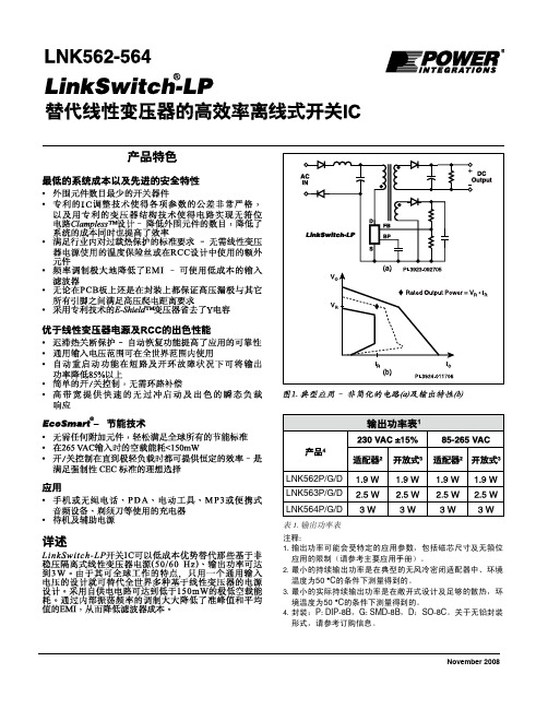
LNK562 - 564使用LinkSwitch - LP的能源Effi古离线式开关集成电路线性变压器更换产品聚焦最低的系统成本和高级安全功能:•最低开关元件数量•非常紧参数公差使用专有IC微调技术和变压器结构™技术使无钳位设计 - 减少元件数量/系统成本,提高effi ciency•符合行业标准要求,热过载保护 - 消除了热熔断器用于线性碾压混凝土设计变压器或其他组件•大大降低EMI的频率抖动 - 使成本低输入滤波器的置信度guration科幻•会见高压漏极之间的爬电距离的要求,所有其他引脚,在印刷电路板和封装都•专有电子变压器消除盾™Y电容优越的性能上线性及碾压混凝土•迟滞热关断保护 - 自动恢复改善高龄可靠性科幻•通用输入范围可在全世界范围内使用•自动重新启动缩短交货方式“> 85%的功率在短路及开环故障条件•简单的开/关控制,无需环路补偿•高带宽提供快速的无过冲和出色的瞬态负载响应的EcoSmart ® - 能源Effi ciency技术•轻松满足全球所有条例与能源effi ciency无需任何附加元件•空载功耗<150 mW的在265 VAC输入•开/关控制提供恒定effi ciency非常轻载 - 理想强制性CEC标准应用•充电器为手机/无绳电话,掌上电脑,电动工具,MP3/portable音频设备,剃须刀等•待机及辅助用品说明使用LinkSwitch - LP的开关电路的成本有效地取代所有不受管制的隔离变压器的线性(50/60 Hz)电源提供高达3瓦的输出功率。
对于世界各地的行动中,单一的通用输入设计取代多元线性变压器基础的设计。
自偏置电路实现极低空载功耗150毫瓦下内部振荡器®表1。
注:1。
输出功率可能是有限的,specifi C应用程序包括核心的大小和无钳位操作参数(请参见关键应用注意事项)。
2。
最小连续输出功率是在典型的无风冷密闭适配器中,50 ° C环境测量。
V-CB564 V-CB574 V-CB584 产品说明书
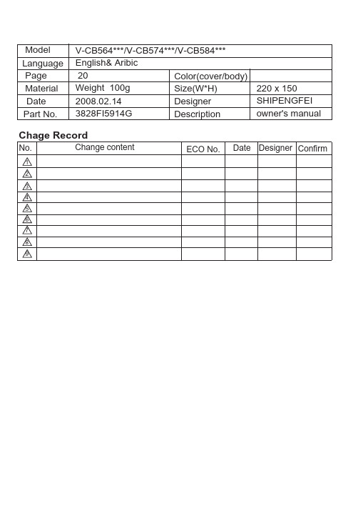
ModelLanguagePage 20Material Size(W*H)Designer Designer ConfirmColor(cover/body)Part No. DescriptionDateNo.Date Chage RecordChange contentECO No.Weight 100g 123456789V -C B564***/V-CB574***/V-CB584*** English & A ribic220 x 1502008.02.14owner's manual3828FI5914G SHIPENGFEIRead and follow all instructions before using your vacuum cleaner to prevent the risk of fire,electric shock, personal injury,or damage when using the vacuum cleaner.This guide do not cover all possible conditions that may occur.Always contact your service agent or manufacturer about problems that you do not understand. This appliance complies with the following ECDirectives :-73/23/EEC,93/68/EEC-Low Voltage Directive–89/336EEC –EMC Directive.This is the safety alert symbol.This symbol alerts you to potential hazards that can kill or hurt you and others.All safety messages will follow the safety alert symbol and either the word “WARNING” or“CAUTION.” These words mean:This symbol will alert you to hazards or unsafe practices which couldcause serious bodily harm or death.This symbol will alert you to hazards or unsafe practices which could causebodily injury or property damage.Connecting the flexible hosePush the end of the head (1)on the flexible hose (2)into the attachment point on the vacuum cleaner.To remove the flexible hose from the vacuum cleaner, press on the button (3) situated on the head, then pull upwards. Assembling the tubes• Metal or plastic tube (34)- Fit together the two tubes by twisting slightly.• Telescopic tube (4)- Push spring latch (5)forward.- Pull out tube to required length.- Release spring latch to lock.• Elbow tube (28)The elbow tube is for uses such as cleaning under the sofa, table and bed easily.- Fit the elbow tube onto the end of the telescopic tube and the grip handle.-If you pull the latch (29), the elbow tube can be bent.- If you stretch the elbow tube, it is returned to its position.Using the cleaning head and Accessory Nozzles(depending on model)Fit the large cleaning head onto the end of the tube.• The 2-position head (6) is equipped with a pedal (7)which allows you to alter its position according to the type of floor to be cleaned.Hard floor position(tiles, parquet floors...). Press on the pedal to lower the brush.Carpet or rug position.Press on the pedal to lift the brush up.• Hard Floor Nozzle (30)Efficient cleaning of hard floors (wood, linoleum, etc.)• Crevice Tool (8)For vacuuming in those normally inaccessible places i.e. reaching cobwebs, or down the side of a sofa!• Dusting brush (9)For vacuuming picture frames, furniture outlines, books and other uneven objects.• Upholstery Nozzle (10)For vacuuming uphostery, mattresses, etc. The thread collectors help to pick up the threads and fluff.How to plug in and usePull out the supply cord to the desired length and plug into the socket.Press button (12)to start the vacuum cleaner. To stop it press the button (12)again. Adjusting the power level (depending on model)• The flexible hose handle (13)has a manual air flow regulator (14)which allows you to briefly reduce the suction level.••Electronic power control (15) Suction capacity increases smoothly up to MAX.How to UseElectronic power control(26)OFF:Power off MIN:Low powerMAX:Full powerPark-System(16)For short breaks during vacuuming, forexample to move a small piece of furnitureor a rug, use the Park system to supportthe flexible hose and cleaning head.ï Slide the hook attached to the large cleaningtool into the slot on the rear of the appliance.Storage(17)When you have switched off and unpluggedthe appliance, press the button (11) toautomatically rewind the cord.You can move or store your appliance in avertical position by sliding the hook on thelarge cleaning head into the clip on theunderside of the appliance.Changing the dust bagThe dustbag needs changing when thecleaner is set to maximum power and thecleaner head is off the floor but the ìbag fullîindicator window(18) is completely colouredred.Even if the dustbag does not appear to befull at this stage, it should be changed, asvery fine dust can clog up the pores of thedust bag.• Turn off the appliance and unplug it.• Open the cover by pressing the hook(19)and lifting it up until it snaps into place.Your appliance is equipped with either apaper dust bag (20)or a fabric dust bag(25).(depending on model)• Take hold of the dust bag by the handle and pull. Remove the bag and throw it away.• To refit a new bag push the cardboardsupport of a new bag into the bag mount (21) until it will go no furthe r.If your appliance is fitted with a fabric dust bag follow the same instructions as above.Empry it and replace it(25). Do not wash it. Note: as the appliance is fitted with a safety device which checks that the bag is in place you cannot close the lid if the bag is not fitted correctly.Cleaning the motor filterThe motor filter is situated inside the appliance between the dust bag and the motor. Each time that you change the air outlet filter we advise you to remove the motor filter(22) and to clean it by tapping to remove the dirt and then replacing it in the vacuum cleaner.Changing the air outlet filters Depending on the model you have chosen your appliance is equipped with different types of filters : foam filter or electrostatic filter(24)or anti-odour charcoal filter or washable HEPA filter(27).• To change these filters remove the cover of the filter compartment(23)situated at the rear of the appliance.• The foam filter should be cleaned regularly by tapping it to remove the dirt.• The electrostatic filter or anti-odor charcoal filter should be changed regularly. (approximately every 6 bag changes)• Wash the washable HEPA filter with water at least once a year.Check that the appliance is correctly plugged in and that the electrical socket is working.• Stop the appliance and unplug it.• Check that the tubes, flexible hose and cleaning tool are not blocked.• Check that the dust bag is not full.Replace if necessary.• Check that the air outlet filter is not blocked. Replace if necessary. What to do if your appliance does not work?What to do when the suction performance reduces?/ P/No.3828FI5914G- 2 -- 3-- 3 -Dd•îM lW«∞J N d°O W∞LÀ•±WØN d°O W,«∞d bÅd¥o,√˺bËL«∞∑F K OL U§d«¡…J M§U¡Æ‹O l∑ª«∞Lßb«ÂÆ∂«qq≥c««∞b∞OqL¥Ø«∞J N d°O W,ôAL K W«∞L∫∑W·Ë«∞Edqn®ªU’∞úU°W√Ë≈º,√ËŪbÂJ M¢K∑«∞Lß´M b«§uœ√¥W˱wA≠•U∞WM l¢H N L N U¥∑u«≠≥c«Boôö‹Jœ«z L U°H MbÀ.«¢∫¢«∞LÆbBw√˱Wqªb«∞∑«∞wMHªËÆU≤uiÊ«∞H u∞XËÆU≤uME.,CÊEC/633/98-E«∞LlÆu«≤O«ô¢±N U“E«∞π∫sUœ«_37/32/CEw:-˰˸¢M∂O te∞Kö±W.º±¸≥c«u≥√Ë¢R–¥psJp√Ê¢I∑K«üd¥s.î¥LX√Ë√≤±e{bc««∞d≥¥M∂Np«∞LwL K W«∞∑ª∫∑U©d«∞L¸U z qØßr«∞o¢Kwqe““±¸ö±WغqË¢F MwØK LWU∞LW∞Kº“¢W∫N I NRA¢M∂O tG√Ë“c¥d”C””¢M∂O t“AO I TNU±U¥Kw:cÁ«∞J K L U‹w¢F M≥±M W«ü‹UË«∞∑¨O d≈∞Ív¢RœÆbßwec««∞d≈∞≥pL U¸¥M∂Nv±«∞L«∞Ld√ËU©ªDî«∞u≠U….b¥WO d…√˺≈ÅU°W§±«üUM W‹¨O dÆb≈∞vÍ¢RœwßË«∞∑ª±e≥pL U¸¥M∂N≈∞c««∞d√Ëvd«∞LU©«∞Ln«∞LL‹¢K.∑K J U≈U°WÅ√˧ºb¥W- 5 -- 6 -- 7 -- 8 -- 9 -/ P/No.3828FI5914G。
LNK562-564中文资料
PI-4526-040207
版本 E F G H
注释 1) 最终发布的数据手册 1) PI-3924已做修改 1) 增加SO-8封装信息 1) 器件订购部分新增无卤素产品信息
日期 10/05 10/05 2/07 11/08
器件订购信息 LNK 562 D N - TL
LinkSwitch产品系列
LP系列号
封装信息
G 塑封表面贴DIP
P 塑封直插式DIP
D 塑封SO-8封装
无铅封装
N 纯镀锡封装(符合RoHS)
G 满足RoHS及无卤素的法规(仅限P和D封装)
带装&卷轴装及其它包装形式
Blank 标准配置
TL
带装&卷轴装,至少1000个,仅适用于G封装。 D封装有2500个。不适用于P封装。
Life Support Policy POWER INTEGRATIONS PRODUCTS ARE NOT AUTHORIZED FOR USE AS CRITICAL COMPONENTS IN LIFE SUPPORT DEVICES OR SYSTEMS WITHOUT THE EXPRESS WRITTEN APPROVAL OF THE PRESIDENT OF POWER INTEGRATIONS. As used herein:
图10.输出导通
图11.峰值负脉冲漏极点
11
版本H 11/08
LNK562-564
图12.击穿电压与温度的特性曲线
图13.频率与温度的特性曲线
图14.限流点与温度的特性曲线
图15.反射引脚与温度的特性曲线
FTI55, FTI56电容式料位计-中文版
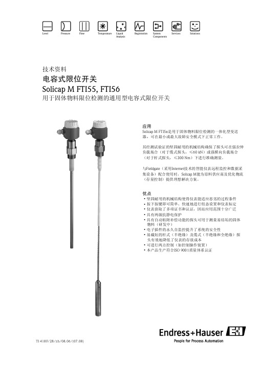
Solicap M FTI55, FTI56
探头的长度范围
重量 间距为1m
接地
射频电磁场 表面 积为1m 2
反电板 (如接地板)
物位
导电性固料 (如煤)
高介电常数的固料 (如面粉)
低介电常数的固料 (如干谷粉)
* LB(覆盖长度) 测量非导电性、低介电常数的固料时,探头缆的长度必须比罐顶与限位高度间的距离长5%, 但不可超过250mm。
—厚壁罐或高介电常数材质的罐壁: 每边长度 为0.7m或直径为Ф0.7m。
射频(HF) 电磁场
所需的最小安装距离为交错安装探头时的 间距。
接地板 接地连接
探头长度 产品特性 相对介电常数ε
导电 非导电
提示! ·上述长度是指除去法兰或螺纹密封件表面至限位点的距离后的最小安装距离。探头的长度
公差请参考第15页的“过程连接”。 ·为了确保用户正常操作,探头的覆盖区与未覆盖区的的电容差至少为5pF。 ·用户不确定罐体材料的介电常数时,请与Endress+Hauser联系。
供应商存量管理
通过Fieldgate远程监控储罐或贮井的物位变化情况,原材料供应商可向客户提供即时供应量信 息,以便客户根据自己的生产计划合理进行安排。供应商利用Fieldgate监控客户的物料储备界线 值,需要时可自行启动下一轮订购过程。客户既可通过E-mail发出简单的购买申请,也可将 XML数据同时记录在买卖双方的计划系统中,实现订购过程的全自动化。
探头的间距 为了防止相互干扰,探头间的安装距离至少为0.5m。在非导电性罐壁的相邻罐体上安装数个 Solicap M探头时,也应遵循此最小安装间距的要求。
最大长度为25mm的螺纹接头应尽可能地 安装至罐体中,尽量避免冷凝和粘附 对测量的影响。
HD74BC564AT中文资料

HD74BC564AOctal D Type Flip Flops With 3 State OutputsADE-205-041 (Z)1st. EditionFeb. 1994 DescriptionThe HD74BC564A provides high drivability and operation equal to or better than high speed bipolar standard logic IC by using Bi-CMOS process. The device features low power dissipation that is about 1/5 of high speed bipolar logic IC, when the frequency is 10 MHZ. The device has eight edge triger D type flip flops with three state outputs in a 20 pin package. Data at the D inputs meeting set up requirements, are transferred to the Q outputs on positive going transitions of the clock input. When the latch enable goes low, data at the D inputs will be retained at the outputs until latch enable returns high again. When a high logic level is applied to the output control input, all outputs go to a high impedance state, regardless of what signals are present at the other inputs and the state of the storage elements.Features• Input/Output are at high impedance state when power supply is off.• Built in input pull up circuit can make input pins be open, when not used.• TTL level input• Wide operating temperature rangeTa = –40 to + 85°CHD74BC564A2Function TableInputsOutput Control CKD Output QL H LL L H L L X Q 0H X XZH :High level L :Low level X :ImmaterialZ:High impedance :Low to high transitionQ 0:Level of Q before the indicated steady state input conditions were established.Pin ArrangementHD74BC564A3Absolute Maximum RatingsItemSymbol Rating Unit Supply voltage V CC –0.5 to +7.0V Input diode current I IK ±30mA Input voltage V IN –0.5 to +7.5V Output voltage V OUT –0.5 to +7.5V Off state output voltage V OUT(off)–0.5 to +5.5V Storage temperature Tstg–65 to +150°CNote:1.The absolute maximum ratings are values which must not individually be exceeded, andfurthermore, no two of which may be realized at the same time.Recommended Operating ConditionsItemSymbol Min Typ Max Unit Supply voltage V CC 4.5 5.0 5.5V Input voltage V IN 0—V CC V Output voltage V OUT 0—V CC V Operating temperature Topr –40—85°C Input rise/fall time*1t r , t f—8ns/VNote:1.This item guarantees maximum limit when one input switches.Waveform: Refer to test circuit of switching characteristics.HD74BC564A Logic Diagram4HD74BC564A5Electrical Characteristics (Ta = –40°C to +85°C)Item Symbol VCC(V)Min Max Unit Test ConditionsInput voltage V IH 2.0—V V IL —0.8V Output voltageV OH 4.5 2.4—V I OH = –3 mA 4.5 2.0—V I OH = –15 mA V OL4.5—0.4V I OL = 24 mA 4.5—0.5V I OL = 48 mA Input diode voltage V IK 4.5—–1.2V I IN = –18 mA Input currentI I5.5—–250µA V IN = 0 V 5.5— 1.0µA V IN = 5.5 V 5.5—100µA V IN = 7.0 V Short circuit output current*1I OS 5.5–100–225mA V IN = 0 or 5.5 V Off state output current I OZH 5.5—50µA V O = 2.7 V I OZL 5.5—–50µA V O = 0.5 V Supply currentI CCL 5.5—29.5mA V IN = 0 or 5.5 V All outputs is “L”I CCH 5.5— 2.5mA V IN = 0 or 5.5 V All outputs is “H”I CCZ 5.5— 2.5mA V IN = 0 or 5.5 V All outputs is “Z”I CCT *25.5—1.5mAV IN = 3.4 or 0.5 V Notes :1.Not more than one output should be shorted at a time and duration of the short circuit should notexceed one second.2.When input by the TTL level, it shows I CC increase at per one input pin.HD74BC564A6Switching Test Method (C L = 50 pF)Ta = 25°C V CC = 5.0 VTa = –40 to 85°C V CC = 5.0V ±10%Item SymbolMin Max Min Max Unit Test Conditions Propagation CK → Q t PLH3.08.0 3.010.0nsSee under figuredelay time t PHL 3.08.0 3.010.0Output enable time t ZH 3.09.0 3.011.0ns t ZL 3.09.0 3.011.0Output disable time t HZ 3.08.0 3.010.0ns t LZ 3.08.0 3.010.0Setup time t s (H) 2.0— 2.0—ns t s (L) 2.0— 2.0—Hold time t h (H) 2.0— 2.0—ns t h (L) 2.0— 2.0—Pulse width t w (H) 6.0— 6.0—ns t w (L) 6.0—6.0—Input capacitance C IN 3.0(Typ)—pF V IN = V CC or GND Output capacitanceC O15.0(Typ)—pFV O = V CC or GNDTest CircuitHD74BC564A Waveforms-1Waveforms-27HD74BC564A Waveforms-38HD74BC564A Package Dimensions9HD74BC564A10HD74BC564A11Cautions 1.Hitachi neither warrants nor grants licenses of any rights of Hitachi’s or any third party’s patent,copyright, trademark, or other intellectual property rights for information contained in this document.Hitachi bears no responsibility for problems that may arise with third party’s rights, includingintellectual property rights, in connection with use of the information contained in this document.2.Products and product specifications may be subject to change without notice. Confirm that you havereceived the latest product standards or specifications before final design, purchase or use.3.Hitachi makes every attempt to ensure that its products are of high quality and reliability. However,contact Hitachi’s sales office before using the product in an application that demands especially high quality and reliability or where its failure or malfunction may directly threaten human life or cause risk of bodily injury, such as aerospace, aeronautics, nuclear power, combustion control, transportation,traffic, safety equipment or medical equipment for life support.4.Design your application so that the product is used within the ranges guaranteed by Hitachi particularlyfor maximum rating, operating supply voltage range, heat radiation characteristics, installationconditions and other characteristics. Hitachi bears no responsibility for failure or damage when used beyond the guaranteed ranges. Even within the guaranteed ranges, consider normally foreseeablefailure rates or failure modes in semiconductor devices and employ systemic measures such as fail-safes, so that the equipment incorporating Hitachi product does not cause bodily injury, fire or other consequential damage due to operation of the Hitachi product.5.This product is not designed to be radiation resistant.6.No one is permitted to reproduce or duplicate, in any form, the whole or part of this document withoutwritten approval from Hitachi.7.Contact Hitachi’s sales office for any questions regarding this document or Hitachi semiconductorproducts.Hitachi, Ltd.Semiconductor & Integrated Circuits.Nippon Bldg., 2-6-2, Ohte-machi, Chiyoda-ku, Tokyo 100-0004, Japan Tel: Tokyo (03) 3270-2111 Fax: (03) 3270-5109Copyright © Hitachi, Ltd., 2000. All rights reserved. Printed in Japan.Hitachi Asia Ltd.Hitachi Tower16 Collyer Quay #20-00,Singapore 049318Tel : <65>-538-6533/538-8577Fax : <65>-538-6933/538-3877URL : .sgURL NorthAmerica : /Europe : /hel/ecg Asia : Japan : http://www.hitachi.co.jp/Sicd/indx.htmHitachi Asia Ltd.(Taipei Branch Office)4/F, No. 167, Tun Hwa North Road,Hung-Kuo Building,Taipei (105), TaiwanTel : <886>-(2)-2718-3666Fax : <886>-(2)-2718-8180Telex : 23222 HAS-TPURL : Hitachi Asia (Hong Kong) Ltd. Group III (Electronic Components) 7/F., North Tower, World Finance Centre, Harbour City, Canton Road Tsim Sha Tsui, Kowloon, Hong Kong Tel : <852>-(2)-735-9218 Fax : <852>-(2)-730-0281 URL : Hitachi Europe Ltd.Electronic Components Group.Whitebrook Park Lower Cookham Road Maidenhead Berkshire SL6 8YA, United Kingdom Tel: <44> (1628) 585000Fax: <44> (1628) 585160Hitachi Europe GmbH Electronic Components Group Dornacher Stra βe 3D-85622 Feldkirchen, Munich Germany Tel: <49> (89) 9 9180-0Fax: <49> (89) 9 29 30 00Hitachi Semiconductor (America) Inc.179 East Tasman Drive,San Jose,CA 95134 Tel: <1> (408) 433-1990Fax: <1>(408) 433-0223For further information write to:Colophon 2.0。
MVL-63XXX中文资料
12/27/2002DescriptionThese Precision Optical Performance oval LEDs are specifically designed for Full Color / Video and Passenger Information signs.High efficiency LED materials are used in these lamps:Aluminum Indium Gallium Phosphide (AlInGaP)for red,amber and green, and Indium Gallium Nitride (InGaN) for true green and blue.Designers can select parallel(where the axis of the leads is parallel to the wide axis of the oval radiation pattern) or perpendicular orientation. Designers can also choose between lamps with or without standoffs.Featuresl Smooth, Consistent Spatial Radiation Patterns l High Luminous Output lEmitting Colors :632 nm Ultra Red 625 nm Red 605 nm Orange 590 nm Amber 573 nm Green 525 nm True Green 470 nm Bluel Superior Resistance to Moisture lChoice of Package OptionsBenefitsl Viewing Angle Designed for Wide Field of View Applicationsl Red, True Green, and Blue Radiation Patterns Matched for Full Color Signs lSuperior Outdoor Environmental PerformanceApplicationsl Full Color / Video Sings lVariable Message SignsPassenger Information AdvertisingTime / TemperatureUnity Opto Technology Co., Ltd.OVAL PRECISIONOPTICAL PERFORMANCE LED LAMPs Technical DataPackage DimensionNotes :1. Tolerance is ± 0.25 mm (.010") unless otherwise noted.2. Protruded resin under flange is 1.5 mm (.059") max.3. Lead spacing is measured where the leads emerge from the package.Part Numbering SchemeMVL-6ABCDwhere A = Leadframe Orientation where C = Color Optionand Package Dimension"UROK" = 632 nm Ultra Red "3" = Parallel Leadframe (3.10 X 3.95 mm) "NUOL" = 625 nm Red "5" = Parallel Leadframe ( 4.26 X 5.06 mm ) "UOL" = 625 nm Red "6" = Perpendicular Leadframe (4.70 X 5.70 mm) "TUOL" = 625 nm Red "7" = Parallel Leadframe ( 3.80 X 5.20 mm ) "SO" = 605 nm Orange "8" = Parallel Leadframe ( 4.56 X 5.20 mm ) "UYL" = 590 nm Amber "9" = Perpendicular Leadframe ( 4.60 X 5.60 mm )"TUYL" = 590 nm Amber "UG" = 573 nm Green"HTG / UTG" = 525 mm True Green "HB / UB" = 470 mm Bluewhere B = Package Color where D = Standoff Option "1" = color diffuse "N/A" = Without "2" = diffuse "-S" = With Stopper"3" = Matching Color "4" = Water ClearAbsolute Maximum Ratings at T A =25o C"UROK""UOL""SO""UYL""HTG""UTG""TUOL""HB""UB""TUYL""UG"mA mW mA Vo C oCV3012510050105100-40 to + 100N/A-30 to + 100300 NOTE1-40 to + 100N/A5-20 to + 855-20 to + 805-20 to + 85Storage TempSolder TemperaturePeak Forward Current(1/10 Duty Cycle 100 µs pulse width)Electrostatic Discharge ThresholdDC Forward Current Reverse Voltage (I R =100µA)Operating Temp Range Power Dissipation100030125100260o C for 5 seconds[ 1.5mm ( 0.06 in. ) below seating plane ]Parameter UnitsInGaNInGaN5-20 to + 80-30 to + 100100AlInGaPAlInGaP3070"NUOL"Notes: 1. Product resistance to electrostatic discharge (ESD) is measured by simulating ESD using a rapid avalanche energy test (RAET).The RAET procedures are designed to approximate the maximum ESD ratings shown. Seller gives no other assurances regarding the ability of Products to withstand ESD.MVL-63XXX AlInGaPDevice Selection Guide (Red, Orange, Amber, Green)Leads Lead Package with Frame Package Min.Typ.Color Stand-OffsOrientationDrawing MajorMinorNo A Yes B No A Yes B No A Yes B No A Yes B No A Yes B No A Yes B No A Yes B No A Yes B No A Yes B No A Yes B No A YesBInGaNDevice Selection Guide (True Green,Blue)No A Yes B No A Yes B No A Yes B No A Yes B No A Yes B No A Yes B No A Yes B No A YesBMVL-631TUYL-S MVL-632TUYL MVL-632TUYL-S Amber diffuse diffuse 400450400450MVL-634UG MVL-634UG-SGreen 573100150Water ClearParallel 110RedWater Clear OrangeWater Clear Amber Water Clearλd(nm)Part Number60300diffuse MVL-632UOL MVL-632UOL-S Red 625150MVL-633UOL Viewing TypicalIntensity Angle Color and Luminous 2θ1/2 (Degrees)Wavelength I F =20mA TypDominant Iv(mcd) at MVL-633UOL-S MVL-634UOL 150300MVL-634UOL-S 150300MVL-634NUOL 150300MVL-633SO Orange 605150300MVL-633SO-S MVL-634SO 150300MVL-634SO-S MVL-634UYL 170350MVL-634UYL-S Amber 590MVL-633UYL 170350MVL-633UYL-S MVL-631TUYL 60MVL-633HTG True Green 525350650MVL-633HTG-S MVL-634HTG 350650MVL-634HTG-S Parallel110GreenWater ClearBlueWater Clear Water ClearWater Clear200MVL-633HB-S MVL-634HB 100200MVL-634HB-S True Green 525250MVL-633HB Blue 470100450MVL-634UB 70140MVL-634UB-SBlue 47070140MVL-634UTG-S MVL-633UTG Water Clear MVL-634NUOL-S BlueMVL-633UB-S MVL-633UB GreenMVL-633UTG-S MVL-634UTG 250450MVL-65XXX AlInGaPDevice Selection Guide (Red, Orange, Amber, Green)LeadsLead Package with Frame Package Min.Typ.Color Stand-OffsOrientationDrawing MajorMinorNo E Yes F No E Yes F No E Yes F No E Yes F No E Yes F No E Yes F No E Yes F No E YesFInGaNDevice Selection Guide (True Green,Blue)No E Yes F No E Yes F No E Yes F No E YesFWater Clear Water Clear MVL-654SO 400MVL-654SO-S MVL-654UOL 400600MVL-654UOL-S 800Water Clear MVL-654UYL 500MVL-654UYL-S Viewing TypicalIntensity Angle Dominant Iv(mcd) at 2θ1/2 (Degrees)Part NumberWavelength I F =20mA Typλd(nm)Color and Luminous 30MVL-653UOL MVL-653UOL-S 400600Red150MVL-654UG 80MVL-654UG-SAmber400MVL-653SO MVL-653SO-S 500700Orange700Water Clear50MVL-653UYL MVL-653UYL-S MVL-653UG-S MVL-653UG 80150Green800MVL-653HTG 7501500MVL-653HTG-S Parallel MVL-653HB 200400BlueMVL-654HTG 750MVL-654HTG-S 1500Water Clear 400Water Clear5030ParallelGreenMVL-654HB 200MVL-654HB-SRed 625Orange 605Amber 590Green 573True Green 525Blue 470MVL-653HB-SMVL-66XXX AlInGaPDevice Selection Guide (Red, Orange, Amber)Leads Lead Package with Frame Package Min.Typ.Color Stand-OffsOrientationDrawing MajorMinorNo G Yes H No G Yes H No G Yes H No G Yes H No G Yes H No G Yes H No G Yes H No G Yes H No G Yes H No G Yes H No G YesHInGaNDevice Selection Guide (True Green,Blue)No G Yes H No G Yes H No G Yes H No G Yes H No G Yes H No G Yes H No G Yes H No G YesHMVL-664UROK 150300Ultra Red MVL-664UROK-S Red 625MVL-663TUOL-S Water Clear Red 200Perpendicular8040BlueWater ClearWater Clear Water ClearBlueGreenGreen200380MVL-663MB-S MVL-664MB 200380MVL-664MB-SMVL-663MB Blue 470MVL-664TUYL MVL-664TUYL-SMVL-664TUOL MVL-664TUOL-S MVL-663SO MVL-663UYL MVL-664SO-S MVL-663HTG 400800200400800MVL-663SO-S MVL-663TUOL 400800Amber Water ClearMVL-663HB-S MVL-663HB 100250Blue 470250MVL-664HB 100MVL-664HB-S MVL-664HTG 6001200MVL-664HTG-S True Green 525MVL-663HTG-S 6001200MVL-663MTG Dominant Iv(mcd) at 2θ1/2 (Degrees)Part NumberColor and Luminous Viewing TypicalIntensity Angle Wavelength I F =20mA Typλd(nm)40MVL-664UYL-S 400500MVL-664UOL MVL-663UOL MVL-663UOL-S MVL-664UOL-S MVL-664SO 250250MVL-664UYL 300Amber 590400MVL-663TUYL MVL-663UYL-S 300Orange 605MVL-663TUYL-S Water ClearAmber Water Clear 600Water Clear80400Water Clear600800Red Perpendicular500OrangeMVL-663MTG-S MVL-664MTG 7001300MVL-664MTG-S True Green 5257001300MVL-67XXX AlInGaPDevice Selection Guide (Red)LeadsLead Package with Frame Package Min.Typ.Color Stand-OffsOrientationDrawing MajorMinorNo C Yes D No C Yes D No C Yes D No C Yes D No C Yes D No C Yes D No C Yes D No C Yes D No C YesDInGaNDevice Selection Guide (True Green,Blue)No C Yes D No C Yes D No C Yes D No C Yes D No C Yes D No C YesDPart NumberParallelGreen GreenGreen diffuseWater ClearBlue diffuseWater ClearParallel Water Clear Red MVL-674HTG-S 1100250500500MVL-672TUOL-S Red 625250MVL-671TUOL 20025012001200250MVL-674HB-S13001300MVL-671HTG True Green 525600700MVL-671HTG-S Blue 470MVL-671UOL MVL-671UOL-S MVL-673UOL-S MVL-674UOL 250MVL-673UOL Viewing TypicalIntensity Angle Color and Luminous Dominant Iv(mcd) at 2θ1/2 (Degrees)Typλd(nm)Wavelength I F =20mA 100MVL-674HB 100MVL-673HB MVL-673HTG-S Blue Water Clear MVL-673HTG MVL-674HTG 700MVL-671HB MVL-671HB-S 100MVL-673HB-S 3070308030707030800800MVL-674UOL-S MVL-672TUOL MVL-673TUOL MVL-673TUOL-S 500MVL-674TUOL MVL-674TUOL-S MVL-671TUOL-S 500Red diffuse diffuse 500900900Red Water Clear Red diffuseMVL-673UG MVL-673UG-S MVL-674UG MVL-674UG-SGreen 5737070150150MVL-68XXX AlInGaPDevice Selection Guide (Red)LeadsLead Package with Frame Package Min.Typ.Color Stand-OffsOrientationDrawingMajorMinorNo I Yes J No I Yes J No I Yes J No I YesJInGaNDevice Selection Guide (True Green,Blue)No I Yes J No I Yes J No I Yes J No I Yes J No I Yes J No I Yes J No I Yes J No I YesJMVL-683HTG MVL-683HTG-S 3001300MVL-684HTG MVL-684HTG-S True Green 5256506501300100200MVL-682HB-S MVL-681HB-S MVL-682HB MVL-684HB 150300MVL-684HB-SMVL-683HB MVL-683HB-S 150601200MVL-681HTG-S MVL-681HB Blue 47010020030diffuseBlue diffuse diffuseBlue Water ClearGreen diffuse ParallelGreen Water Clear MVL-684UOL 400800MVL-682HTG 6001200MVL-682HTG-S MVL-681HTG 600MVL-684UOL-S400800Red MVL-683UOL-S MVL-683UOL Red diffuse Parallel diffuse60Water Clear30MVL-681UOL Red 625300600MVL-681UOL-S MVL-682UOL 300600MVL-682UOL-S Wavelength I F =20mA Typλd(nm)Dominant Iv(mcd) at 2θ1/2 (Degrees)Part NumberColor and Luminous Viewing TypicalIntensity AngleMVL-69XXX AlInGaPDevice Selection Guide (Red)Leads Lead Package with Frame Package Min.Typ.Color Stand-OffsOrientationDrawing MajorMinorNo K Yes L No K Yes L No K Yes L No K YesLMVL-693TUYL-S MVL-694TUYL MVL-694TUYL-SAmber 590MVL-694TUOL MVL-694TUOL-S MVL-693TUOL-S Red200025502510001000100020002000λd(nm)Wavelength I F =20mA 50Dominant Iv(mcd) at 2θ1/2 (Degrees)TypViewing TypicalIntensity Angle Color and Luminous Part NumberAmberWater ClearPerpendicularWater Clear 1000Red 625MVL-693TUOL 2000MVL-693TUYLElectrical/Optical Characteristics at T A =25o CParameterSymbolMin.Typ.Max.UnitsTest ConditionsTypical Viewing Angle Major/Minor MVL-63XXX 110/60 MVL-65XXX 50/30 MVL-66XXX 80/40 MVL-67XXX 70/30 MVL-68XXX 60/30 MVL-69XXX50/25Peak/Dominant Wavelength MVL-6XXUROK(-S)637/632Peak and Dominant of MVL-6XXNUOL(-S)630/625Wavelength of MVL-6XXUOL(-S)630/625Spectral MVL-6XXTUOL(-S)630/625Distribution at MVL-6XXSO(-S)610/605I F = 20 mAMVL-6XXUYL(-S)592/590 MVL-6XXTUYL(-S)592/590 MVL-6XXUG(-S)575/573 MVL-6XXUTG(-S)523/525 MVL-6XXHTG(-S)523/525 MVL-6XXUB(-S)468/470 MVL-6XXHB(-S)468/470Spectral HalfwidthUltra Red (λd = 632 nm)22Wavelength Width at Red (λd = 625 nm)17Spectral Orange (λd = 605 nm)13Distribution Amber (λd = 590 nm)171/2 Power Point Yellow Green (λd = 573 nm)20at I F = 20mATure Green (λd = 525 nm)40 Blue (λd = 470 nm)26Forward Voltage AlInGaP 1.6 2.1 2.6 InGaN 2.83.54.2Reverse Current AlInGaP100 InGaN "HTG" "HB"100 "UTG" "UB"10I F = 20mA2θ1/2DegreesV FVµAV R = 5Vλp / λdnmÄλ1/2nmI F = 20mAI RR E L A T I V E I N T E N S I T YWAVELENGTH(nm)Figure 1.RELATIVE INTENSITY012345020406080100R a d i a n t L u m i n o u s I n t e n s i t yForward Current I F (mA)FIG.4 RELATIVE LUMINOUS INTENSITYVS. FORWARD CURRENTF o r w a r d C u r r e n t I F (m A )F o r w a r d C u r r e n t I F (m A )Ambient Temperature T A (oC )FIG.3 FORWARD CURRENT VS. AMBIENT TEMPERATUREForward VoltageV F (V)FIG.2 FORWARD CURRENT VS. FORWARD VOLTAGE0102030405060020406080100InGa N AlInGaP10203040501.21.62.02.42.83.23.64.04.4InGaNAlInGaPR e l a t i v e L u m i n o u s I n t e n s i t y0.30.1R e l a t i v e L u m i n o u s I n t e n s i t y0.30.1R e l a t i v e L u m i n o u s In t e n s i t y0.30.100.51400425450475500525550575595620645670695AmberRed OrangeTure GreenGreenBlueR e l a t i v e L u m i n o u s I n t e n s i t y0.30.10.30.1R e l a t i v e L u m i n o u s I n t e n s i t yR e l a t i v e L u m i n o u s I n t e n s i t y0.30.1Unity Oval LEDs Bin TableLuminous IntensityBIN RANGEJ MAX 70MIN41100141199I V (mcd) @ I F =20mA5881115K L M N 225331851593563796S T U282130318434616529223981126230326R 163O P QUnity OVAL LED Bin CodesUnity OVAL LED Bin Codes。
- 1、下载文档前请自行甄别文档内容的完整性,平台不提供额外的编辑、内容补充、找答案等附加服务。
- 2、"仅部分预览"的文档,不可在线预览部分如存在完整性等问题,可反馈申请退款(可完整预览的文档不适用该条件!)。
- 3、如文档侵犯您的权益,请联系客服反馈,我们会尽快为您处理(人工客服工作时间:9:00-18:30)。
T-1 3/4 (φ5mm)InGaN LED LAMPs
MVL-564BS
Description
Package Dimensions
The MVL-564BS, a blue source color device, is made with
InGaN ( on SiC substrate) LED die.
The package is T-1 3/4(φ5mm) water clear plastic lens package.
Applications
l Full color displays & moving message signs
l Solid state incandescent replacement bulbs l High ambient panel indicators l Color printers & scanners l
Medical & Analytical instruments
Features
l High performance - 3.5mW (450nm) l Superior SiC substrate technology l Excellent chip to chip consistency l
High reliability
Absolute Maximum Ratings
Parameter
Symbol Maximum Rating
Unit Peak Forward Current(1/10 Duty Cycle@1KHz )I pf 100mA Continuous Forward Current I af 30mA Reverse Voltage
V R 5
V
Operating Temperature Range T
opr -20
o C to +80o C Storage Temperature Range
T stg -30o C to +100o C Electrostatic Discharge Threshold(HBM)
E ot
1000
V 09/11/2000
Unity Opto Technology Co., Ltd.
@ T A =25o C
Notes :
1. Tolerance is ±0.25 mm (.010") unless otherwise noted.
2. Protruded resin under flange is 0.8 mm (.031") max.
3. Lead spacing is measured where the leads emerge from the package.
Unit: mm ( inches )
MVL-564BS
Optical-Electrical Characteristics
Parameter Test Conditions Symbol Min .Typ .Max .Unit .Luminous Intensity I F =20mA I V 200400 -mcd Forward Voltage I F =20mA V F - 3.7 4.0V Reverse Current I R - -10µA Dominant Wavelength I F =20mA λd -450 -nm Viewing Angle
I F =20mA
2θ1/2
-30
-
deg.
Typical Optical-Electrical Characteristic Curves
V R =5V
@ T A =25o C
Unity Opto Technology Co., Ltd.
0.5
1
380
450
520
590
660
Wavelength (nm)
FIG.1 RELATIVE INTENSITY LUMINOUS VS. WAVELENGTH
R e l a t i v e L u m i n o u s I n t e n s i t y
510152025300
1
2
3
4
Forward Voltage (V)
FIG.2 FORWARD CURRENT VS.
FORWARD VOLTAGE
F o r w a r d C u r r e n t I F (m A )
010203040
25
50
75
100
F o r w a r d C u r r e n t I F (m A )
Ambient Temperature (o C )FIG.3 FORWARD CURRENT VS.AMBIENT TEMPERATURE
0.00
0.250.500.751.001.251.500
5
10
15
20
25
30
Forward Current I F (mA)
FIG.4 RELATIVE LUMINOUS INTENSITY VS. FORWARD CURRENT
R e l a t i v e L u m i n o u s I n t e n s i t y N o r m a l i z e d a t I F =20m A。