CH4_V8 - Controlling Data Access
211171490_甲烷催化部分氧化制合成气催化剂的研究进展

化工进展Chemical Industry and Engineering Progress2023 年第 42 卷第 4 期甲烷催化部分氧化制合成气催化剂的研究进展阮鹏1,杨润农1,2,林梓荣1,孙永明2(1 广东佛燃科技有限公司,广东 佛山 528000;2 中国科学院广州能源研究所,广东 广州 510640)摘要:天然气是一种前景广阔的清洁燃料,甲烷作为天然气的主要成分,其高效利用具有重要的现实意义。
在众多甲烷转化途径中,甲烷催化部分氧化(CPOM )具有能耗低、合成气组分适宜、反应迅速等优势。
本文简要介绍了CPOM 反应机理,即直接氧化机理和燃烧-重整机理;重点综述了过渡金属、贵金属、双金属和钙钛矿这四类CPOM 催化剂的研究现状;分析了反应温度、反应气体碳氧比和反应空速对CPOM 反应特性的影响;阐述了积炭和烧结这两种催化剂失活的主要原因及应对措施。
根据研究结果可知,通过选取合适的催化剂组分、采用优化的制备方法、精确控制催化剂活性组分分布和微观结构等措施,可以保证更多的有效活性位更稳定地暴露在催化剂表面,以此提高催化性能(包括甲烷转化率、合成气选择性、合成气生成率、反应稳定性等)。
最后指出了对CPOM 催化剂微观结构的合理设计与可控制备以及对CPOM 反应机理的深入研究仍将是今后关注的重点。
关键词:甲烷;部分氧化;催化剂;合成气;多相反应中图分类号:TE644 文献标志码:A 文章编号:1000-6613(2023)04-1832-15Advances in catalysts for catalytic partial oxidation of methane to syngasRUAN Peng 1,YANG Runnong 1,2,LIN Zirong 1,SUN Yongming 2(1 Guangdong Foran Technology Company Limited, Foshan 528000, Guangdong, China; 2 Guangzhou Institute of EnergyConversion, Chinese Academy of Science, Guangzhou 510640, Guangdong, China)Abstract: Natural gas is a promising clean fuel. The efficient use of methane, the major component of natural gas, is of great practical importance. Among many methane conversion routes, catalytic partial oxidation of methane (CPOM) has the advantages of low energy consumption, suitable syngas fraction and rapid reaction. This paper briefly introduced the CPOM reaction mechanisms (i.e. direct oxidation mechanism and combustion-reforming mechanism), reviewed the current research on four types of CPOM catalysts (i.e. transition metal, noble metal, bimetal and perovskite catalysts), analysed the effects of reaction temperature, carbon to oxygen molar ratio of reactant gas and reaction space velocity on CPOM reaction characteristics, and explained the two main causes of catalyst deactivation (i.e. carbon deposition and sintering) together with their countermeasures. According to the results of the research, the catalytic performance (including methane conversion, syngas selectivity, syngas yield, reaction stability) could be improved by selecting suitable catalyst components, adopting an optimized preparation method and precisely controlling the distribution of active components and microstructure of the catalyst. These method could ensure that more active sites are consistently exposed to the surface of catalyst. Finally, it综述与专论DOI :10.16085/j.issn.1000-6613.2022-1109收稿日期:2022-06-13;修改稿日期:2022-08-22。
controllogix PLC技术参考手册

2
Publication 1756-TD001D-EN-E - May 2011
1756 ControlLogix Controllers Specifications
1756 Contrபைடு நூலகம்lLogix Controllers
The ControlLogix controller provides a scalable controller solution that is capable of addressing a large amount of I/O points. The ControlLogix controller can be placed into any slot of a ControlLogix I/O chassis and multiple controllers can be installed in the same chassis. ControlLogix controllers can monitor and control I/O across the ControlLogix backplane, as well as over network links. To provide communication for a ControlLogix controller, install the appropriate communication interface module into the chassis.
1756 ControlLogix Controllers Specifications
Important User Information
Solid state equipment has operational characteristics differing from those of electromechanical equipment. Safety Guidelines for the Application, Installation and Maintenance of Solid State Controls (publication SGI-1.1 available from your local Rockwell Automation sales office or online at /literature/) describes some important differences between solid state equipment and hard-wired electromechanical devices. Because of this difference, and also because of the wide variety of uses for solid state equipment, all persons responsible for applying this equipment must satisfy themselves that each intended application of this equipment is acceptable. In no event will Rockwell Automation, Inc. be responsible or liable for indirect or consequential damages resulting from the use or application of this equipment. The examples and diagrams in this manual are included solely for illustrative purposes. Because of the many variables and requirements associated with any particular installation, Rockwell Automation, Inc. cannot assume responsibility or liability for actual use based on the examples and diagrams. No patent liability is assumed by Rockwell Automation, Inc. with respect to use of information, circuits, equipment, or software described in this manual. Reproduction of the contents of this manual, in whole or in part, without written permission of Rockwell Automation, Inc., is prohibited. Throughout this manual, when necessary, we use notes to make you aware of safety considerations.
LabVIEW Datalogging and Supervisory Control Module

RELEASE AND UPGRADE NOTESLabVIEW Datalogging and™Supervisory Control ModuleVersion 8.5This document describes the system requirements and the process ofinstalling the LabVIEW Datalogging and Supervisory Control (DSC)Module8.5 and the DSC Module Run-Time System8.5. This documentalso describes the new features available with version8.5 and compatibilityand upgrade issues you might encounter when you use version8.5.If you want to upgrade the DSC Module from the DSC Module7.x orearlier, refer to the LabVIEW Datalogging and Supervisory ControlModule8.2 Release and Upgrade Notes. The Upgrading from theLabVIEW DSC Module7.x section provides important information forupgrade users. Refer to the National Instruments Web site at /infoand enter the info code dsc820 to access the LabVIEW Datalogging andSupervisory Control Module8.2 Release and Upgrade Notes.Refer to the Getting Started with the LabVIEW Datalogging andSupervisory Control Module manual for exercises you can complete tofamiliarize yourself with the DSC Module.ContentsSystem Requirements (2)Installation Instructions (2)New Features in the DSC Module8.5 (3)Using the Statistical Process Control Toolkit (3)Using the NI OPC Servers Application (3)Logging OPC Client Diagnostic Information (4)Supporting Modbus Advanced Data Types (4)Using EPICS Client I/O Servers (4)Using the Multi-Segment Pipe Control (5)New DSC Module VIs (5)Enhancements to the Multiple Variable Editor (5)Enhancements to the SharedVariableIO Properties (6)LabVIEW DSC Module Release and Upgrade Notes Compatibility Issues (6)Considerations for the DSC Module Run-Time System.........................6Known Issues. (7)System RequirementsTo use the DSC Module, your computer must meet the following minimumsystem requirements:•Windows Vista/XP/2000.•A minimum of 800MB free disk space. You can increase computer resources to increase performance of DSC Module applications.•A minimum of 512MB of RAM. NI recommends 1GB of RAM.•LabVIEW Base, Full, or Professional Development Systemversion 8.5. Refer to the LabVIEW Release Notes for LabVIEWsystem requirements.The DSC Module does not support Windows NT/Me/98/95/Server 2003.Installation InstructionsComplete the following steps to install the DSC Module.1.Log in to the development computer as an administrator or as a user with administrative privileges.2.Install LabVIEW 8.5 from the LabVIEW 8.5 installation CD. Referto the LabVIEW Release Notes for information about installing theLabVIEW development system.3.Install the DSC Module from the LabVIEW DSC Module 8.5installation CD. Follow the instructions that appear on the screen.The DSC Module installs program files, documentation, andexamples.Note By default, the NI Keyboard Filter Driver is not installed. The NI Keyboard Filter Driver activates special security features, including the ability to restrict users fromswitching between applications by pressing the <Alt-Tab> keys. This driver does not work on laptop computers or on computers with hibernation enabled.4.Restart the computer.New Features in the DSC Module8.5The following sections describe the new features in the DSC Module8.5.Refer to the LabVIEW Help for more information about using these newfeatures.Using the Statistical Process Control ToolkitBy default, the LabVIEW Statistical Process Control Toolkit is installedwhen you install the DSC Module. Use the Statistical Process Control VIsto monitor, analyze, and control processes. For example, you can estimateprocess distributions and capabilities, calculate and plot histograms, andplot and fit normal probability distribution functions to the histograms.Refer to the readme_SPC.html file, available by selecting Start»AllPrograms»National Instruments»LabVIEW8.5»Readme, for moreinformation about using the Statistical Process Control Toolkit.Using the NI OPC Servers ApplicationUse the NI OPC Servers application to transfer data from industrial devicesand systems to client applications on a host machine. The NI OPC Serversapplication enables data sharing between a variety of applications, such ashuman-machine interface software, manufacturing execution systems, andenterprise resource planning applications.By default, the NI OPC Servers application is installed when you install theDSC Module. You have a temporary license for a two-hour evaluationperiod. If you do not activate the NI OPC Servers application license, thisapplication runs in evaluation mode for two hours. When the evaluationperiod expires, you must activate a valid license to continue using theNI OPC Servers application.Refer to the NI OPC Servers Help, available by selecting Start»AllPrograms»National Instruments»NI OPC Servers»NI OPC ServersHelp, for more information about activating and using the NI OPC Serversapplication.© National Instruments Corporation3LabVIEW DSC Module Release and Upgrade NotesLogging OPC Client Diagnostic InformationLogging diagnostic information about OPC Client I/O servers can help youdebug an OPC system. You can use the options on the Diagnostics pageof the Configure OPC Client I/O Server dialog box to log diagnosticinformation about the OPC Client I/O servers you create.OPC Client I/O servers communicate with both LabVIEW and the SharedVariable Engine. The OPC Client I/O servers log this communication toHTML log files. The log files highlight communication activities in blueand communication errors in red. The log files also provide explanations ofthe communication errors. You therefore can use the log files to debug anOPC system.Supporting Modbus Advanced Data TypesIn addition to supporting Boolean values and 16-bit unsigned integers, theModbus and Modbus Slave I/O servers support other data types, including16-bit signed integers, 32-bit signed and unsigned integers, 32-bitfloating-point numbers, and arrays of these data types. These data typesenable the Modbus and Modbus Slave I/O servers to access and updatemultiple Modbus points simultaneously.Using EPICS Client I/O ServersEPICS, or the Experimental Physics and Industrial Control System, is a setof open-source software tools you can use to develop large, distributedcontrol systems. EPICS systems use the Channel Access (CA) networkprotocol to pass data between EPICS clients and EPICS servers, alsoknown as input/output controllers (IOCs). The CA network protocol is anEthernet-based protocol.The DSC Module acts as an EPICS client. With the DSC Module, you canmonitor and update process variables that an IOC publishes using the CAnetwork protocol. You can create an EPICS Client I/O server to readprocess variables from and write process variables directly to an IOC.In the Project Explorer window, right-click a target, such as the MyComputer target, and select New»I/O Server from the shortcut menu. Inthe Create New I/O Server dialog box, select EPICS Client and click theContinue button to create an EPICS Client I/O server.LabVIEW DSC Module Release and Upgrade Using the Multi-Segment Pipe ControlUse the Multi-Segment Pipe control to represent real-world pipe networksthat you need to monitor. Use the Multi-Segment Pipe control to reshapeand resize an entire pipe network interactively. You can add pipe segmentsto this pipe network, remove pipe segments, and change the direction inwhich the flanges point. You also can change the color of the pipe networkto customize what the pipe network represents.New DSC Module VIsThe DSC Module8.5 provides the following new VIs:•Browse Database VI•Deploy Libraries VI•NI Security Get Group List of User VI•NI Security Get User List of Group VIRefer to the LabVIEW Help for more information about using thesenew VIs.Enhancements to the Multiple Variable EditorUse the Multiple Variable Editor window to configure a large number ofshared variables at one time. Right-click a project library and select EditVariables from the shortcut menu to display the Multiple Variable Editorwindow.The Multiple Variable Editor window includes the followingenhancements:•Select and edit multiple shared variables at once using the new tableformat.•Search across several shared variables at once using the new advancedsearch options. Click the Find button to display the search options.•Copy and paste property values across shared variables by clicking theCopy and Paste buttons.•Sort shared variable properties by right-clicking a property column andselecting Sort Ascending or Sort Descending from the shortcutmenu.You no longer need to use the Multiple Variable Editor window toimport or export shared variable configuration information to or from aspreadsheet file. To import the information, right-click a project libraryand select Import Variables from the shortcut menu. To export theinformation, right-click a project library and select Export Variables fromthe shortcut menu.© National Instruments Corporation5LabVIEW DSC Module Release and Upgrade NotesEnhancements to the SharedVariableIO PropertiesSharedVariableIO properties in the following categories are available inreal-time operating systems.•Description•Initial Value•Scaling•Update DeadbandCompatibility IssuesWhen you open a VI saved in a previous version of the DSC Module, theVI might be broken if the VI contains an indicator, constant, or controlcreated from the shared variable value change notification output of thefollowing VIs:•Cancel Value Change Notifications VI•Enable Value Change Notifications VI•Request Value Change Notifications VITo fix the broken VI, delete the indicator, constant, or control. Then createa new indicator, constant, or control from the shared variable valuechange notification output and wire it to the appropriate parameter. Considerations for the DSC Module Run-Time SystemIf you want to run applications built with LabVIEW, the DSC Module, andthe LabVIEW Application Builder on a computer without the DSC Moduleinstalled, you must install the DSC Module Run-Time System. The DSCModule Run-Time System contains components to enable the DSCfeatures in the built applications.To use the DSC Module Run-Time System, the computer must meet thefollowing minimum system requirements:•Windows Vista/XP/2000.• A minimum of 600MB free disk space.• A minimum of 512MB of RAM.LabVIEW DSC Module Release and Upgrade Complete the following steps to install the DSC Module Run-Time System.1.Log in to the computer as an administrator or as a user withadministrative privileges.2.Install the DSC Module Run-Time System8.5 from the LabVIEWDSC Module Run-Time System8.5 installation CD.3.Follow the instructions that appear on the screen.4.Restart the computer.Known IssuesRefer to the readme_DSC.html file, available by selecting Start»AllPrograms»National Instruments»LabVIEW8.5»Readme or on theLabVIEW DSC Module installation CD, for information about knownissues with the DSC Module.Refer to the readme_DSC_RTS.html file, available by selecting Start»AllPrograms»National Instruments»LabVIEW8.5»Readme or on theLabVIEW DSC Module Run-Time System installation CD, for informationabout known issues with the DSC Module Run-Time System.© National Instruments Corporation7LabVIEW DSC Module Release and Upgrade NotesNational Instruments, NI, , and LabVIEW are trademarks of National Instruments Corporation.Refer to the Terms of Use section on /legal for more information about NationalInstruments trademarks. Other product and company names mentioned herein are trademarks or tradenames of their respective companies. For patents covering National Instruments products, refer to theappropriate location: Help»Patents in your software, the patents.txt file on your CD, or/patents. Refer to the LabVIEW Help for a listing of the conditions and disclaimers.© 2005–2007 National Instruments Corporation. All rights reserved.374128C-01Aug07。
mssql监控磁盘空间告警实现方法

mssql监控磁盘空间告警实现方法这几天突然有个想法:希望能够自动监控、收集数据库服务器的磁盘容量信息,当达到一个阀值后,自动发送告警邮件给DBA,将数据库磁盘详细信息告知DBA,提醒DBA做好存储规划计划,初步的想法是通过作业调用存储过程来实现(每天调用一次),这样避免了我每天每台数据库服务器都上去检查一下,尤其是手头的数据库服务器N多的情况,这样可以避免我每天浪费无谓的时间。
如果大家有更好的建议和方法,欢迎指点一二,我整理、修改了三个存储过程如下:存储过程1:SP_DiskCapacityAlert1.prc说明:需要通过调用OLE 自动存储过程获取磁盘信息,而这些组件,基于服务器的安全配置,通常是禁用的,我们在存储过程通过sp_configure开启这个服务,调用服务完毕后,又通过sp_configure 禁用该服务。
另外,数据库服务器都位于内网,因此安全问题应该不大。
复制代码代码如下:USE master;GOSET ANSI_NULLS ONGOSET QUOTED_IDENTIFIER ONGOIF EXISTS (SELECT 1 FROM dbo.sysobjects WHERE id = OBJECT_ID(N'sp_diskcapacity_alert1') AND OBJECTPROPERTY(id,'IsProcedure') =1)DROP PROCEDURE sp_diskcapacity_alert1;GO--========================================= ========================================= ================================-- ProcedureName : sp_diskcapacity_alert1 -- Author : Kerry-- CreateDate : 2013-05-02-- Description : 获取数据库所在服务器的磁盘容量,当达到阀值是,发送告警邮件,提醒DBA做好存储规划计划/************************************************************** ****************************************************Modified Date Modified User Version Modified Reason2013-05-6 Kerry V01.00.00 修改HTML 输出样式.以及磁盘容量输出改为GB*************************************************************** ****************************************************/--========================================= ========================================= ================================CREATE PROCEDURE [dbo].[sp_diskcapacity_alert1](@Threshold NUMERIC)ASSET NOCOUNT ONDECLARE @Result INT;DECLARE @objectInfo INT;DECLARE @DriveInfo CHAR(1); DECLARE @T otalSize VARCHAR(20); DECLARE @OutDrive INT;DECLARE @UnitMB BIGINT; DECLARE @HtmlContent NVARCHAR(MAX) ; DECLARE @FreeRat NUMERIC; DECLARE @EmailHead VARCHAR(120); SET @UnitMB = 1048576;--创建临时表保存服务器磁盘容量信息CREATE TABLE #DiskCapacity([DiskCD] CHAR(1) ,FreeSize INT ,TotalSize INT);INSERT #DiskCapacity([DiskCD], FreeSize )EXEC master.dbo.xp_fixeddrives;EXEC sp_configure 'show advanced options', 1RECONFIGURE WITH OVERRIDE;EXEC sp_configure 'Ole Automation Procedures', 1;RECONFIGURE WITH OVERRIDE;EXEC @Result = master.sys.sp_OACreate 'Scripting.FileSystemObject',@objectInfo OUT;DECLARE CR_DiskInfo CURSOR LOCAL FAST_FORWARDFOR SELECT DiskCD FROM #DiskCapacityORDER by DiskCDOPEN CR_DiskInfo;FETCH NEXT FROM CR_DiskInfo INTO @DriveInfoWHILE @@FETCH_STATUS=0BEGINEXEC @Result = sp_OAMethod @objectInfo,'GetDrive', @OutDrive OUT, @DriveInfoEXEC @Result = sp_OAGetProperty @OutDrive,'TotalSize', @TotalSize OUTUPDATE #DiskCapacitySET TotalSize=@T otalSize/@UnitMBWHERE DiskCD=@DriveInfoFETCH NEXT FROM CR_DiskInfo INTO @DriveInfoENDCLOSE CR_DiskInfoDEALLOCATE CR_DiskInfo;EXEC @Result=sp_OADestroy @objectInfoEXEC sp_configure 'show advanced options', 1RECONFIGURE WITH OVERRIDE;EXEC sp_configure 'Ole Automation Procedures', 0;RECONFIGURE WITH OVERRIDE;EXEC sp_configure 'show advanced options', 0RECONFIGURE WITH OVERRIDE;SELECT @FreeRat =FreeRateFROM (SELECT ROW_NUMBER() OVER (ORDER BY FreeSize / ( TotalSize * 1.0 ) ASC) AS RowIndex,CAST(( FreeSize / ( TotalSize * 1.0 ) ) * 100.0 AS INT) AS FreeRateFROM #DiskCapacity) TWHERE RowIndex = 1;IF @FreeRat <= @ThresholdBEGINIF @FreeRat > 10 AND @FreeRat <=20SET @EmailHead ='数据库磁盘容量告警(告警级别3)'ELSE IF @FreeRat >=5 AND @FreeRat <=10SET @EmailHead ='数据库磁盘容量告警(告警级别4)'ELSESET @EmailHead ='数据库磁盘容量告警(告警级别5)'SET @HtmlContent =+ N'<html>'+ N'<style type="text/css">'+ N' td {border:solid #9ec9ec; border-width:0px 1px 1px 0px; padding:4px 0px;}'+ N' table {border:1px solid #9ec9ec; width:100%;border-width:1px 0px 0px 1px;text-align:center;font-size:12px}' + N'</style>'+ N'<H1 style="color:#FF0000; text-align:center;font-size:14px">' + @EmailHead +'</H1>'+ N'<table >'+ N'<tr><th>磁盘盘符</th><th>总大小(GB)</th><th>已用空间(GB)</th><th>剩余空间(GB)</th>'+ N'<th>已用比例(%)</th><th>剩余比例(%)</th></tr >' +CAST ( ( SELECTtd = DiskCD , '',td = STR(TotalSize*1.0/1024,6,2) , '',td = STR((TotalSize - FreeSize)*1.0/1024,6,2) , '',td = STR(FreeSize*1.0/1024,6,2) , '',td = STR(( TotalSize - FreeSize)*1.0/(TotalSize)* 100.0,6,2), '',td = STR(( FreeSize * 1.0/ ( TotalSize ) ) * 100.0,6,2) , ''FROM #DiskCapacityFOR XML PATH('tr'), TYPE ) AS NVARCHAR(MAX) ) + N'</table></html>' ;EXEC msdb.dbo.sp_send_dbmail@profile_name = 'DataBase_DDL_Event', --指定你自己的profile_name@recipients='****@', --指定你要发送到的邮箱@subject = '服务器磁盘空间告警',@body = @HtmlContent,@body_format = 'HTML' ;ENDDROP TABLE #DiskCapacity;RETURN;GO存储过程2:SP_DiskCapacityAlert2.prc说明:需要启用xp_cmdshell来获取磁盘信息,关于xp_cmdshell安全隐患,一般该功能都是禁用的。
GE Grid Solutions DS Agile C264双机架模块化变电站控制器说明书

C264 AVR provides:
Active and reactive compounding in order to maintain the voltage at a remote location
Homing in order to adjust a transformer to the voltage of the busbar to which it will be connected
GE Grid Solutions
DS Agile C264
Dual-bay Modular Substation Controller
The DS Agile C264 substation controller is a sophisticated solution supporting multiple applications and functions for substation control, communication, monitoring, protection, and automation. Flexibility, reliability and ease of use are among the top features required in a substation computer; the DS Agile C264 has these features.
Trip Circuit Supervision
The purpose of this function is to supervise the continuity of the trip circuit of a circuit breaker. Two options are available to supervise the circuit breaker's trip circuit continuity: two wires and four wires to monitor continuity either when the circuit breaker is closed or when it is opened or closed.
底盘的英语单词
底盘的英语单词chassis(of a car)n.底盘,底座,底架baseplaten.底板;基础板,基板例句1.木构架和金属底盘都没有采取防腐措施。
Neither the timber frame nor metal chassis were protected against rot.2.车子底盘的3块隔热板已经脱落了。
Three insulating panels had come adrift from the base of the vehicle.3.他会把钢丝绳拴在汽车底盘上,用卷扬机把汽车吊到运河岸上。
He would attach a cable around the chassis of the car and winch it up on to the canal bank4.空中客车有一个未来模型概念,它有一个乘客舱,可以从在路上行驶中的底盘上分离出来,并由直升机式的机器接走。
Airbus has a futuristic modular concept involving a passenger capsule that can be detached from the road-going chassis and picked up by a helicopter-type machine.5.用CAD技术进行汽车底盘总布置设计方法的研究Study on General Layout of the vehicle Chassis with CAD6.PID算法在汽车底盘测功机中的应用与实现The Application and Implementation of PID Algorithm In Automotive Chassis Dynamometer7.基于VB的客车底盘总布置参数化设计系统Parameterized Layout Design System for Bus Chassis Based on Visual Basic8.零件INNER TUBE用于汽车的底盘减震系统,采用线材冷成型工艺生产。
OXuPCI954_DS

External—Free ReleaseOxford Semiconductor, Inc.1900 McCarthy Boulevard, Suite 210 © Oxford Semiconductor, Inc. 2007F EATURES• Four 16C950 High performance UART channels • 8-bit Pass-through Local Bus (PCI Bridge )• IEEE1284 Compliant SPP/EPP/ECP parallel port (with external transceiver)• Efficient 32-bit, 33 MHz, multi-function target-only PCIcontroller, fully compliant to PCI Local Bus Specification 3.0 and PCI Power Management Specification 1.1 • Software compatible with OXmPCI954• UARTs fully software compatible with 16C550-type devices • UART operation up to 60 MHz via external clock source. Up to 20 MHz with the crystal oscillator• Baud rates up to 60 Mbps in external 1x clock mode and 15 Mbps in asynchronous mode• 128-byte deep FIFO per transmitter and receiver • Flexible clock prescaler, from 1 to 31.875• Automated in-band flow control using programmable Xon/Xoff in both directions•Automated out-of-band flow control using CTS#/RTS# and/or DSR#/DTR#• Programmable RS485 turnaround delay• Arbitrary trigger levels for receiver and transmitter FIFO interrupts and automatic in-band and out-of-band flow control• Infra-red (IrDA) receiver and transmitter operation • 9-bit data framing, as well as 5, 6, 7, and 8 bits • Detection of bad data in the receiver FIFO• Global Interrupt Status and readable FIFO levels to facilitate implementation of efficient device drivers.• Local registers to provide status/control of device functions • 11 multi-purpose I/O pins, which can be configured as input interrupt pins or ‘wake-up’• Auto-detection of a wide range of optional MICROWIRE TM compatible EEPROMs, to re-configure device parameters • Function access , to pre-configure each function prior to handover to generic device drivers • Operation via I/O or memory mapping• 3.3 V or 5 V operation (PCI Universal Voltage)• Extended operating temperature range: -40° C to 85° C •176-pin LQFP packageD ESCRIPTIONThe OXuPCI954 is a single chip solution for PCI-based serial and parallel expansion add-in cards. It is a dual function PCI device, where function 0 offers four ultra-high performance OX16C950 UARTs, and function 1 is configurable either as an 8-bit local bus or a bi-directional parallel port.Each UART channel in the OXuPCI954 is the fastest available PC-compatible UART, offering data rates up to 15 Mbps and 128-byte deep transmitter and receiver FIFOs. The deep FIFOs reduce CPU overhead and allow utilization of higher data rates. Each UART channel is software compatible with the widely used industry-standard 16C550 devices (and compatibles), as well as the OX16C95x family of high performance UARTs. In addition to increased performance and FIFO size, the UARTs also provide the full set of OX16C95x enhanced features including automated in-band flow control, readable FIFO levels, etc.To enhance device driver efficiency and reduce interrupt latency, internal UARTs have multi-port features such as shadowed FIFO fill levels, a global interrupt source register and Good-Data Status, readable in four adjacent DWORD registers visible to logical functions in I/O space and memory space.Expansion of serial ports beyond four channels is possible using the 8-bit pass-through Local Bus function. This provides a general address/data bus and interrupt capability to a discrete UART part, such as the Oxford SemiconductorOX16C954. Other controllers could be used to provide capabilities beyond additional UART ports. The addressable space provided by the Local Bus can be increased up to 256 bytes, and divided into four chip-select regions. This flexible expansion scheme caters for cards with up to 20 serial ports using external 16C950, 16C954 or compatible devices, or composite applications such as combined serial and parallel port expansion cards. Serial port cards with up to 20 ports (or with 4 serial ports and a parallel port) can be designed without redefining any device or timing parameters.The parallel port is an IEEE 1284 compliant SPP/EPP/ECP parallel port that fully supports the existing Centronics interface. The parallel port can be enabled in place of the local bus. A n external bus transceiver is required for 5V parallel port operation if device is 3.3V sourced.For full flexibility, all the default configuration register values can be overwritten using an optional M ICROWIRE compatibleserial EEPROM. This EEPROM can also be used to provide function access to pre-configure devices on the local bus/parallel port, prior to any PCI configuration accesses and before control is handed to (generic) device drivers.The OXuPCI954 can be used to replace the OXmPCI954 in a PCI application where quad UARTs and a local bus/parallel port functionality are required.OXuPCI954 DATA SHEETIntegrated High Performance Quad UARTs,8-bit Local Bus/Parallel Port,3.3 V and 5 V (Universal Voltage) PCI Interface .Improvements of the OXuPCI954 over Discrete SolutionsHigher degree of integrationThe OXuPCI954 device offers four internal 16C950 high-performance UARTs and an 8-bit local bus or abi-directional parallel port.Multi-function deviceThe OXuPCI954 is a multi-function device to enable users to load individual device drivers for the internal serial ports, drivers for the peripheral devices connected to the local bus or drivers for the internal parallel port.Quad Internal OX16C950 UARTsThe OXuPCI954 device contains four ultra-high performance UARTs, which can increase driver efficiency by using features such as the 128-byte deep transmitter and receiver FIFOs, flexible clock options, automatic flow control, programmable interrupt and flow control trigger levels and readable FIFO levels. Data rates are up to 60 Mbps.Improved access timingAccess to the internal UARTs require zero or one PCI wait state. A PCI read transaction from an internal UART can complete within five PCI clock cycles and a write transaction to an internal UART can complete within four PCI clock cycles. Reduces interrupt latencyThe OXuPCI954 device offers shadowed FIFO levels and Interrupt status registers on the internal UARTs and the MIO pins. This reduces the device driver interrupt latency. Power managementThe OXuPCI954 device complies with the PCI Power Management Specification 1.1 and the Microsoft Communications Device-class Power Management Specification 2.0 (2000). Both functions offer the extended capabilities for Power Management. This achieves significant power savings by enabling device drivers to power down the PCI functions. For function 0, this is through switching off the channel clock, in power state D3. Wake-up (PME# generation) can be requested by either functions. For function 0, this is via the RI# inputs of the UARTs in the power-state D3 or any modem line and SIN inputs of the UARTs in power-state D2. For function 1, this is via the MIO[2] input.Optional EEPROMThe OXuPCI954 device can be reconfigured from an external EEPROM to the end-user’s requirements. However, this is not required in many applications as the default values are sufficient for typical applications. An overrun detection mechanism built into the EEPROM controller prevents the PCI system from ‘hanging’ due to an incorrectly programmed EEPROM.R EVISION H ISTORYRevision Modification May 2007 First publication.Sep 2007 Feature revision, including removal of D3coldT ABLE OF C ONTENTS1OXuPCI954 Device Modes (6)2Block Diagram (7)3Pin Information—176-Pin LQFP (8)3.1Mode ‘0’ Quad UARTs + 8-bit Local Bus (8)3.1.1Mode ‘1’ : Quad UARTs + Parallel Port (9)3.2Pin Descriptions (10)4Configuration and Operation (16)5PCI Target Controller (17)5.1Operation (17)5.2Configuration Space (17)5.2.1PCI Configuration Space Register Map (18)5.3Accessing Logical Functions (20)5.3.1PCI Access to Internal UARTs (21)5.3.2PCI Access to 8-bit Local Bus (22)5.3.3PCI Access to Parallel Port (22)5.4Accessing Local Configuration Registers (23)5.4.1Local Configuration and Control Register ‘LCC’ (Offset 0x00) (23)5.4.2Multi-purpose I/O Configuration Register ‘MIC’ (Offset 0x04) (24)5.4.3Local Bus Timing Parameter Register 1 ‘LT1’ (Offset 0x08) (26)5.4.4Local Bus Timing Parameter Register 2 ‘LT2’ (Offset 0x0C) (27)5.4.5UART Receiver FIFO Levels ‘URL’ (Offset 0x10) (28)5.4.6UART Transmitter FIFO Levels ‘UTL’ (Offset 0x14) (29)5.4.7UART Interrupt Source Register ‘UIS’ (Offset 0x18) (29)5.4.8Global Interrupt Status and Control Register ‘GIS’ (Offset 0x1C) (30)5.5PCI Interrupts (31)5.6Power Management (32)5.6.1Power Management of Function 0 (32)5.6.2Power Management of Function 1 (33)5.6.3Universal Voltage (34)5.7Unique Bar Option – for Function 0 (35)6Internal OX16C950 UARTs (36)6.1Operation – Mode Selection (36)6.1.1450 Mode (36)6.1.2550 Mode (36)6.1.3Extended 550 Mode (36)6.1.4750 Mode (36)6.1.5650 Mode (36)6.1.6950 Mode (37)6.2Register Description Tables (38)6.3UART Reset Configuration (41)6.3.1Hardware Reset (41)6.3.2Software Reset (41)6.4Transmitter and Receiver FIFOs (42)6.4.1FIFO Control Register ‘FCR’ (42)6.5Line Control and Status (43)6.5.1False Start Bit Detection (43)6.5.2Line Control Register ‘LCR’ (43)6.5.3Line Status Register ‘LSR’ (44)6.6Interrupts and Sleep Mode (45)6.6.1Interrupt Enable Register ‘IER’ (45)6.6.2Interrupt Status Register ‘ISR’ (46)6.6.3Interrupt Description (46)6.6.4Sleep Mode (47)6.7Modem Interface (47)6.7.1Modem Control Register ‘MCR’ (47)6.7.2Modem Status Register ‘MSR’ (48)6.8Other Standard Registers (48)6.8.1Divisor Latch Registers ‘DLL and DLM’ (48)6.8.2Scratch Pad Register ‘SPR’ (48)6.9Automatic Flow Control (49)6.9.1Enhanced Features Register ‘EFR’ (49)6.9.2Special Character Detection (50)6.9.3Automatic In-band Flow Control (50)6.9.4Automatic Out-of-band Flow Control (50)6.10Baud Rate Generation (51)6.10.1General Operation (51)6.10.2Clock Prescaler Register ‘CPR’ (51)6.10.3Times Clock Register ‘TCR’ (51)6.10.4External 1x Clock Mode (53)6.10.5Crystal Oscillator Circuit (53)6.11Additional Features (54)6.11.1Additional Status Register ‘ASR’ (54)6.11.2FIFO Fill Levels ‘TFL and RFL’ (54)6.11.3Additional Control Register ‘ACR’ (54)6.11.4Transmitter Trigger Level ‘TTL’ (55)6.11.5Receiver Interrupt. Trigger Level ‘RTL’ (55)6.11.6Flow Control Levels ‘FCL’ and ‘FCH’ (56)6.11.7Device Identification Registers (56)6.11.8Clock Select Register ‘CKS’ (56)6.11.9Nine-bit Mode Register ‘NMR’ (57)6.11.10Modem Disable Mask ‘MDM’ (57)6.11.11Readable FCR ‘RFC’ (58)6.11.12Good-data Status Register ‘GDS’ (58)6.11.13Port Index Register ‘PIX’ (58)6.11.14Clock Alteration Register ‘CKA’ (58)6.11.15RS485 Delay Enable ‘RS485_DLYEN’ (58)6.11.16RS485 Delay Count ‘RS485_DLYCNT’ (59)7Local bus (60)7.1Overview (60)7.2Operation (60)7.3Configuration and Programming (61)8Bidirectional Parallel Port (62)8.1Operation and Mode Selection (62)8.1.1SPP Mode (62)8.1.2PS2 Mode (62)8.1.3EPP Mode (62)8.1.4ECP Mode (62)8.2Parallel Port Interrupt (63)8.3Register Description (63)8.3.1Parallel Port Data Register ‘PDR’ (64)8.3.2ECP FIFO Address / RLE (64)8.3.3Device Status Register ‘DSR’ (64)8.3.4Device Control Register ‘DCR’ (64)8.3.5EPP Address register ‘EPPA’ (65)8.3.6EPP Data Registers ‘EPPD1-4’ (65)8.3.7ECP Data FIFO (65)8.3.8Test FIFO (65)8.3.9Configuration A Register (65)8.3.10Configuration B Register (65)8.3.11Extended Control Register ‘ECR’ (65)9Serial EEPROM (66)9.1Specification (66)9.1.1Zone 0: Header (67)9.1.2Zone 1: Local Configuration Registers (68)9.1.3Zone 2: Identification Registers (69)9.1.4Zone 3: PCI Configuration Registers (69)9.1.5Zone 4: Power Management DATA (and DATA_SCALE Zone) (70)9.1.6Zone 5: Function Access (70)10Operating Conditions (72)10.1DC Electrical Characteristics (72)11AC Electrical Characteristics (76)11.1PCI Bus Timings (76)11.2Local Bus (77)11.3Serial Ports (79)12Timing Waveforms (80)13Package Information (95)13.1176-Pin LQFP (95)14Ordering Information (96)1OX U PCI954D EVICE M ODESThe OXuPCI954 supports two modes of operation. These modes are summarized in the following table.Device Mode Mode Pin Selection Functionality0 MODE = 0 Function 0 : Quad UARTs Function 1 : 8-bit local bus1 MODE = 1 Function 0 : Quad UARTs Function 1 : Parallel Port* The OXuPCI954 is not pin-compatible with the OX16PCI954 or the OXmPCI954, but is the same in all other aspects.2B LOCK D IAGRAMFIFOSELMODEAD[31:0]C/BE[3:0]#PCI_CLKFRAME#DEVSEL#IRDY#TRDY#STOP#PARPERR#IDSELRST#INTA#PME#XTLIXTLOUART_Clk_Out Local_Bus ClkEE_DIEE_CSEE_CKEE_DOSOUT[3:0]SIN[3:0]RTS[3:0]DTR[3:0]CTS[3:0]DSR[3:0]DCD[3:0]RI[3:0]MIO[10:0]PD[7:0]ACK#PEBUSYSLCTERR#SLIN#INIT#AFD#STB#LBA[7:0]LBD[7:0]LBCS[3:0]LBWR#LBRD#LBRSTDATA_DIR OXuPCI954 Block DiagramOSCDIS XTLSEL3P IN I NFORMATION—176-P IN LQFP 3.1Mode ‘0’ Quad UARTs + 8-bit Local Bus7 NC. Do not connect these pins:23, 40, 41, 136, 137, 138, 1393.1.1Mode ‘1’ : Quad UARTs + Parallel Port15 NC. Do not connect these pins:23, 40, 41, 74, 112, 113, 114, 115, 116, 117, 124, 136, 137, 138, 1393.2Pin DescriptionsFor the actual pinouts of the OXuPCI954 device (for the various modes), refer to the Section 3, Pin Information. The I/O direction key table is on page 15.PCI Interface – All ModesPin Dir1Name Description149, 150, 151, 154, 155,157, 158, 160, 164, 165,167, 168, 169, 170, 171,174, 13, 14, 15, 17, 18, 20,24, 25, 27, 28, 31, 32, 33,34, 35, 39P_I/O AD[31:0] Multiplexed PCI Address/Data bus161, 175, 12, 26 P_I C/BE[3:0]# PCI Command/Byte enable146 P_I CLK PCI system clock (33MHz)176 P_IFRAME#CycleFrame5 P_ODEVSEL#DeviceSelect1 P_IIRDY#Initiatorready2 P_OTRDY#Targetready6 P_O STOP# Target Stop request10 P_I/OPAR Parity8 P_OSERR#Systemerror7 P_I/OPERR#Parityerror163 P_I IDSEL Initialization device select144 P_I RST# PCI system reset142 P_ODINTA# PCIinterrupt147 P_OD PME# Power management eventSerial Port Pins – All ModesPin Dir1Name Description50 I FIFOSEL FIFO select. For backward compatibility with 16C550,16C650 and 16C750 devices the UARTs’ FIFO depth is 16when FIFOSEL is low. The FIFO size is increased to 128when FIFOSEL is high. The unlatched state of this pin isreadable by software. The FIFO size may also be set to 128by setting FCR[5] when LCR[7] is set, or by putting thedevice into Enhanced mode.82, 81, 63, 62 O(h)SOUT[3:0]IrDA_Out[3:0] These four pins are present in all modes but they can serve one of two functions, as follows:UART serial data outputs.UART IrDA data output when MCR[6] of the corresponding channel is set in Enhanced mode.91, 73, 72, 55I(h) I(h) SIN[3:0]IrDA_In[3:0]These four pins are present in all modes but they can serveone of two functions, as follows:UART serial data inputs.UART IrDA data input when IrDA mode is enabled (seeabove).Serial Port Pins – All ModesPin Dir1Name Description89, 76, 71, 57 I(h) DCD[3:0]# Active-low modem data-carrier-detect input 84, 79, 65, 60O(h) O(h) O(h) DTR[3:0]#485_En[3:0]Tx_Clk_Out[3:0]These four pins are present in all modes but they can serveone of three functions, as follows:Active-low modem data-terminal-ready output. If automatedDTR# flow control is enabled, the DTR# pin is asserted anddeasserted if the receiver FIFO reaches or falls below theprogrammed thresholds, respectively.In RS485 half-duplex mode, the DTR# pin may beprogrammed to reflect the state of the transmitter empty bitto automatically control the direction of the RS485transceiver buffer (see register ACR[4:3]).Transmitter 1x clock (baud rate generator output). Forisochronous applications, the 1x (or Nx) transmitter clockmay be asserted on the DTR# pins (see register CKS[5:4]).83, 80, 64, 61 O(h) RTS[3:0]# Active-low modem request-to-send output. If automatedRTS# flow control is enabled, the RTS# pin is deassertedand reasserted whenever the receiver FIFO reaches or fallsbelow the programmed thresholds, respectively.85, 78, 67, 59 I(h) CTS[3:0]# Active-low modem clear-to-send input. If automated CTS#flow control is enabled, upon deassertion of the CTS# pin,the transmitter will complete the current character and enterthe idle mode until the CTS# pin is reasserted. Note: any in-band flow control characters are transmitted regardless ofthe state of the CTS# pin.86, 77, 66, 58I(h) I(h) DSR[3:0]#Rx_Clk_In[3:0]These four pins are present in all modes but they can serveone of two functions, as follows:Active-low modem data-set-ready input. If automated DSR#flow control is enabled, upon deassertion of the DSR# pin,the transmitter will complete the current character and enterthe idle mode until the DSR# pin is reasserted. Note: any in-band flow control characters are transmitted regardless ofthe state of the DSR# pin.External receiver clock for isochronous applications. TheRx_Clk_In is selected when CKS[1:0] = ‘01’.90, 75, 70, 56 I(h)I(h) RI[3:0]#Tx_Clk_In[3:0]Active-low modem Ring-Indicator inputExternal transmitter clock. This clock can be used by thetransmitter (and indirectly by the receiver) when CKS[6]=’1’.Clock Interface Pins – All ModesPin Dir 1 Name Description49 I/OXTLOCrystal oscillator output when OSCDIS = ‘0’.External clock source input when OSCDIS = ‘1’48 I XTLI Crystal oscillator input when OSCDIS = ‘0’, up to 20MHz.N/C when OSCDIS = ‘1’45 I OSCDIS Oscillator disable.When 0, the internal crystal oscillator is enabled and a crystal needs to be attached to XTLI/XTLO.XTLSEL must be set according to the crystal frequency that is used (up to 20Mhz).When 1, the internal crystal oscillator is disabled and an external oscillator source (up to 60MHz) can be input to XTLO. XTLI is N/C and XTLSEL must be 0130 I XTLSEL Defines the frequency of the crystal attached to XTLI/XTLO(when OSCDIS = ‘0’)0 = 1 MHz – 12 MHz 1 = 12 MHz – 20 MHz8-bit Local Bus – Mode 0Pin Dir 1 Name Description 111O UART_CLK_Out Buffered crystal output. This clock can drive external UARTsconnected to the local bus. Can be enabled / disabled by software.123 O(h) LBRST Local bus active-high reset. 124 O LBRST# Local bus active-low reset. 104 O LBDOUT Local bus data out enable. This pin can be used by externaltransceivers; it is high when LBD[7:0] are in output mode and low when they are in input mode.74 O LBCLK Buffered PCI clock. Can be enabled / disabled by software. 114, 115, 116, 117 O(h) O(h) LBCS[3:0]# LBDS[3:0]# Local bus active-low Chip-Select (Intel mode).Local bus active-low Data-Strobe (Motorola mode).112 O O LBWR# LBRDWR# Local bus active-low write-strobe (Intel mode).Local bus Read-not-Write control (Motorola mode).113 O Z LBRD# Hi-Z Local bus active-low read-strobe (Intel mode).Permanent high impedance (Motorola mode).105, 106, 108, 109 118, 119, 120, 122 O(h) LBA[7:0] Local bus address signals. 96, 97, 98, 99 100, 101, 102, 103I/O(h) LBD[7:0] Local bus data signals.Parallel Port – Mode 1Pin Dir 1 NameDescription123 I(h) I(h) ACK#INTR#Acknowledge (SPP mode). ACK# is asserted (low) by the peripheral to indicate that a successful data transfer has taken place.Identical function to ACK# (EPP mode).122 I(h) PEPaper Empty. Activated by printer when it runs out of paper. 120 I(h) I(h) BUSYWAIT#Busy (SPP mode). BUSY is asserted (high) by the peripheral when it is not ready to accept data.Wait (EPP mode). Handshake signal for interlocked IEEE 1284 compliant EPP cycles.109 OD(h) O(h) SLIN#ADDRSTB#Select (SPP mode). Asserted by host to select the peripheral.Address strobe (EPP mode) provides address read and write strobe.119 I(h) SLCT Peripheral selected. Asserted by peripheral when selected. 118 I(h) ERR#Error. Held low by the peripheral during an error condition. 108 OD(h) O(h) INIT#INIT#Initialize (SPP mode). Commands the peripheral to initialize.Initialize (EPP mode). Identical function to SPP mode. 106 OD(h) O(h) AFD#DATASTB# Auto Feed (SPP mode, open-drain).Data strobe (EPP mode) provides data read and write strobe.105 OD(h) O(h) STB#WRITE#Strobe (SPP mode). Used by peripheral to latch data currently available on PD[7:0].Write (EPP mode). Indicates a write cycle when low and a read cycle when high . 96, 97, 98, 99, 100, 101, 102, 103I/O(h) PD[7:0] Parallel data bus.104OPDOUTParallel port data out enable. This pin should be used by external transceivers for 5 V signaling; it is high when PD[7:0] are in output mode and low when they are in input mode.Multi-purpose and External Interrupt Pins – All ModesPin Dir1Name DescriptionMODE0 1135 --135I/O(h)OMIO0NCMulti-purpose I/O 0. Can drive high or low, or assert a PCIinterrupt.Output Driving ‘0’. Can be left as a No-connect.134 134 134134I/O(h)MIO1NCMulti-purpose I/O 1. Can drive high or low, or assert a PCIinterrupt (as long as LCC[6:5] = “00”).Output Driving ‘0’ (when LCC[6:5] ≠ ‘00’)Can be left as a No-Connect.133 133 133133I/O(h)IMIO2PME_InMulti-purpose I/O 2. When LCC[7] = 0, this pin can drive highor low, or assert a PCI interrupt.Input power management event. When LCC[7] is set thisinput pin can assert a function 1 PME#.93, 94, 95, 125, 126, 127, 128, 132 I/O(h) MIO[10:3] Multi-purpose I/O pins. Can drive high or low, or assert a PCIinterrupt.EEPROM Pins – All ModesPin Dir1Name Description53 OEE_CKEEPROMclock.52 O EE_CS EEPROM active-high Chip Select.54 IU(h) EE_DI EEPROM data in, with internal pull-up.When the serial EEPROM is connected, this pin should bepulled up using a 1-10k resistor. When the EEPROM is notused the internal pull-up is sufficient.Pin to be connected to the external EEPROM’s EE_DO pin(if used).51 O EE_DO EEPROM data out.Pin to be connected to the external EEPROM’s EE_DI pin(if used).Table 1: Pin DescriptionsI/O Direction Key P_I PCI input 3.3 V Only P_O PCI output / PCITristates 3.3 V Only P_I/O PCI bi-directional 3.3 V Only P_OD PCI open drain 3.3 V OnlyI Input LVTTL level I(h) Input LVTTL level, 5 V tolerant IU(h) Input with internal pull-up LVTTL level, 5 V tolerant I/O(h) Bi-Directional LVTTL level, 5 V tolerantO Output Standard Output O(h) Output 5 V tolerant (High Voltage BI-Direct in output mode) OD Open drain Standard Open-drain Output OD(h) Open drain 5 V tolerant (High Voltage BI-Direct in open-drain mode) NC No connectG Ground V VoltageMiscellaneous PinsPin Dir 1 NameDescription44 IMODEMode selector Pin0 : Function 0 : Quad UART. Function 1 : 8-bit local bus.1 : Function 0 : Quad UART. Function 1 : Parallel port.Power and GroundPinType Name Description19, 42, 47, 69, 88, 107, 131, 148VVDDPower Supply (3.3 V)11, 22, 36, 140, 156, 162, 173 V VIOPCI I/O Universal VoltageDefines the (clamping) voltage of the PCI I/O Buffers.To be connected to the VIO pin of the PCI connector. 3, 4, 9, 16, 21, 29, 30, 37, 38, 43, 46, 68, 87, 92, 110, 121, 129, 141, 143, 145, 152, 153, 159, 166, 172G GNDPower Supply Ground (0 V)4C ONFIGURATION AND O PERATIONThe OXuPCI954 is a multi-function, target-only PCI device, compliant with the PCI Local Bus Specification, Revision 3.0 and the PCI Power Management Specification, Revision 1.1.The OXuPCI954 affords maximum configuration flexibility by treating the internal UARTs, the local bus and the parallel port as separate logical functions. Each function has its own configuration space and is therefore recognized and configured by the PCI BIOS separately. The functions used are configured by the Mode Selection Pin as shown in Section 1 OXuPCI954 Device Modes.The OXuPCI954 is configured by system start-up software during the bootstrap process that follows bus reset. The system scans the bus and reads the vendor and device identification codes from any devices it finds. It then loads device-driver software according to this information and configures the I/O, memory and interrupt resources. Device drivers can then access the functions at the assigned addresses in the usual fashion, with the improved data throughput provided by PCI.Each function operates as though it was a separate device. However there are a set of Local Configuration Registers that can be used to enable signals and interrupts, configure timings, and improve the efficiency of multi-port drivers. This architecture enables separate drivers to be installed for each function. Generic port drivers can be hooked to use the functions individually, or more efficient multi-port drivers can hook both functions, accessing the Local Configuration Registers from either.All registers default after reset to suitable values for typical applications such a 4/8 port serial, or combo 4-port serial/1-port parallel add-in cards. However, all identification, control and timing registers can be redefined using an optional serial EEPROM.5PCI T ARGET C ONTROLLER5.1OperationThe OXuPCI954 responds to the following PCI transactions:-•Configuration access: The OXuPCI954 responds to type 0 configuration reads and writes if the IDSELsignal is asserted and the bus address is selecting theconfiguration registers for function 0 or 1. The devicewill respond to the configuration transaction by asserting DEVSEL#. Data transfer then follows. Anyother configuration transaction will be ignored by theOXuPCI954.•I/O reads/writes: The address is compared with the addresses reserved in the I/O Base Address Registers(BARs). If the address falls within one of the assignedranges, the device will respond to the I/O transactionby asserting DEVSEL#. Data transfer follows thisaddress phase. For the UARTs and 8-bit local buscontroller, only byte accesses are possible. For I/Oaccesses to these regions, the controller comparesAD[1:0] with the byte-enable signals as defined in thePCI specification. The access is always completed;however if the correct BE signal is not present thetransaction will have no effect.•Memory reads/writes: These are treated in the same way as I/O transactions, except that the memoryranges are used. Memory access to single-byte regions is always expanded to DWORDs in theOXuPCI954. In other words, OXuPCI954 reserves aDWORD per byte in single-byte regions. The deviceallows the user to define the active byte lane usingLCC[4:3] so that in Big-Endian systems the hardwarecan swap the byte lane automatically. For Memorymapped access in single-byte regions, the OXuPCI954 compares the asserted byte-enable withthe selected byte-lane in LCC[4:3] and completes theoperation if a match occurs, otherwise the access willcomplete normally on the PCI bus, but it will have noeffect on either the internal UARTs or the local buscontroller.•All other cycles (64-bit, special cycles, reserved encoding etc.) are ignored.The OXuPCI954 will complete all transactions as disconnect-with-data, i.e. the device will assert the STOP# signal alongside TRDY#, to ensure that the Bus Master does not continue with a burst access. The exception to this is Retry, which will be signaled in response to any access while the OXuPCI954 is reading from the serial EEPROM.The OXuPCI954 performs medium-speed address decoding as defined by the PCI specification. It asserts the DEVSEL# bus signal two clocks after FRAME# is first sampled low on all bus transaction frames which address the chip. The internal UARTs are accessed with zero wait states inserted. Fast back-to-back transactions are supported by the OXuPCI954 as a target, so a bus master can perform faster sequences of write transactions to the UARTs or local bus when an inter-frame turn-around cycle is not required.The device supports any combination of byte-enables to the PCI Configuration Registers and the Local Configuration Registers. If a byte-enable is not asserted, that byte is unaffected by a write operation and undefined data is returned upon a read.The OXuPCI954 performs parity generation and checking on all PCI bus transactions as defined by the standard. Note this is entirely unrelated to serial data parity which is handled within the UART functional modules themselves. If a parity error occurs during the PCI bus address phase, the device will report the error in the standard way by asserting the SERR# bus signal. However if that address/command combination is decoded as a valid access, it will still complete the transaction as though the parity check was correct.The OXuPCI954 does not support any kind of caching or data buffering in addition to that already provided within the UARTs by the transmit and receive data FIFOs. In general, registers in the UARTs and on the local bus can not be pre-fetched because there may be side-effects on read.5.2Configuration SpaceThe OXuPCI954 is a dual-function device, where each logical function has its own configuration space. All required fields in the standard header are implemented, plus the Power Management Extended Capability register set. The format of the configuration space is shown in the following tables.In general, writes to any registers that are not implemented are ignored, and all reads from unimplemented registers return 0.。
SPARC V8处理器基于PC 104嵌入式计算机模块设计说明书
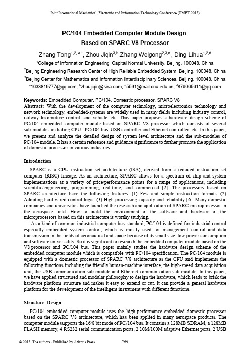
Joint International Mechanical, Electronic and Information Technology Conference (JIMET 2015)PC/104 Embedded Computer Module DesignBased on SPARC V8 ProcessorZhang Tong1,2, a *, Zhou Jiqin3,b,Zhang Weigong2,3,c , Ding Lihua1,2,d1College of Information Engineering, Capital Normal University, Beijing, 100048, China2Beijing Engineering Research Center of High Reliable Embedded System, Beijing, 100048, China 3Beijing Center for Mathematics and Information Interdisciplinary Sciences, Beijing, 100048, China a*****************,b******************,c*************,d****************Keywords: Embedded Computer, PC/104, Domestic processor, SPARC V8Abstract: With the development of the computer technology, microelectronics technology and network technology, embedded-systems are widely used in many fields including industry control, railway locomotive control, and vehicle, etc. This paper proposes a hardware design scheme of PC/104 embedded computer module based on SPARC V8 processor which consists of several sub-modules including CPU , PC/104 bus, USB controller and Ethernet controller, etc. In this paper, we present and analyze the detailed design of system level architecture and the sub-modules of PC/104 module. It has a certain reference and guidance significance to further promote the application of domestic processor in various industries.IntroductionSPARC is a CPU instruction set architecture (ISA), derived from a reduced instruction set computer (RISC) lineage. As an architecture, SPARC allows for a spectrum of chip and system implementations at a variety of price/performance points for a range of applications, including scientific/engineering, programming, real-time, and commercial [2]. The processors based on SPARC architecture have the following features: (1) Few and simple instruction formats. (2) Adopting hard-wired control logic. (3) High processing capacity and reliability [6]. Many domestic companies and universities have launched the research and application of SPARC microprocessor in the aerospace field. How to build the environment of the software and hardware of the microprocessors based on this architecture is worthy studying.As a kind of common industrial computer bus standard, PC/104 is defined for industrial control especially embedded system control, which is mostly used for management control and data transmission in the fields of aeronautical and space because of its small size, low power consumption and software universality. So it is significant to research the embedded computer module based on the V8 processor and PC/104 bus. This paper mainly studies the hardware design scheme of the embedded computer module which is compatible with PC/104 specification. The PC/104 module is equipped with a domestic processor of SPARC V8 architecture as the CPU and implements the following functions including the friendly human-machine interface, the high-speed data acquisition unit, the USB communication sub-module and Ethernet communication sub-module. In this paper, we have applied structured and modular philosophy to design the hardware, which leads to brisk the hardware platform structure and makes it easy to extend or cut. It can provide a general hardware platform for the development of the intelligent instrument with different functions.Structure DesignPC/104 embedded computer module uses the high-performance embedded domestic processor based on the SPARC V8 architecture, which has been applied in many aerospace products. The computer module supports the 16/8 bit mode of PC/104 bus. It contains a 128MB SDRAM, a 128MB FLASH memory, 4 RS232 serial communication ports, 2 10M/100M adaptive Ethernet ports, 2 USBports and a VGA display port with 1600*1200 display resolution. In this PC/104 module, we have configured VxWorks operating system including BSP, USB keyboard mouse driver, Ethernet driver, UART driver, TFFS file system and other software driver [1]. Drivers are designed for the corresponding hardware devices, such as USB, Ethernet, UART and display control circuit to manage the underlying hardware, which can provide a standardized and hardware-independent interface to the high-level application software. Fig. 1 shows the main block diagram of PC/104 embedded computer module.Fig. 1 The main block diagram of PC/104 embedded computer moduleHardware Module Design Based on Domestic ProcessorCPU Sub-module A 32-bit microprocessor based on SPARC V8 architecture with the high degree of integration and high performance is adopted in this design. Fig. 2 shows the internal structure of the processor. From Fig. 2, we can see the processor chip contains an on-chip integer processing unit IU, a floating-point unit (FPU), independent data caches and instruction caches, 5 stage pipeline, hardware multiplier and divider and so on. Moreover, interrupt controller, hardware debug unit with tracking buffer storage (DSU), two common timer (timer0, timer1), serial interface, PCI interface, watchdog timer and memory controller supporting PROM, SRAM, SDRAM and I/O space accessing and so on are integrated in this processor chip[4].Fig. 2 The structure diagram of SPARC V8 CPUPC/104 Bus Sub-module The electrical logic of PC/104 specification uses ISA bus specification. It defines two types ofaddress space including I/O space and memory space, supporting 8-bit and 16-bit data accessing. The hardware of PC/104 can configure 11 interrupt sources and provide 7 DMA Channels. Due to the characteristics of V8 processor chip, in the designing of PC/104 module, we use dual space mapping mode to support the 8/16 read-write functions of PC/104 bus. The I/O space of V8 processor has the following two regions:(1) One region is used to deal with the 16-bit read-write functions of PC/104 bus, which can be divided into two subspaces, namely I/O space and memory space. The PC/104 bus accessing operations to this space are all considered to be 16-bit read-write mode. In this region, the MEMCS16# and IOCS16# signals are all ignored (assuming the device accessed is 16 bits).(2) Another region is specifically designed for 8-bit read-write functions of PC/104 bus, which can also be divided into two subspaces, namely IO space and storage space. The PC/104 bus accessing operations to this space are considered to be 8-bit read-write mode. The accessed device is served as an 8-bit device or a 16-bit device by the MEMCS16# and IOCS16# signal and the PC/104 data bus is mapped into the corresponding space of the processor.In order to improve the efficiency of bus accessing and the controlling flexibility, we implement the bus sequential control logic circuits on a FPGA chip. Through this designing method, the PC/104 bus sequence can be set flexibly by configuring the software, for example, the length (T1) of the address latch signal (BALE) or the default length (T2) of the bus access cycle can be changed by modifying the control register. The PC/104 bus sequence waveforms are shown in Fig. 3. In this figure, the term T4 is the time gap between the BALE falling edge and read-write signal falling edge, which has a minimum value of zero.As shown in Fig. 3, the length of T1 can be set by the BALEW domain of PC/104 bus sequence control register (ISATIMING). The length of T4 is 0~10ns. The length of T3 is T2-T1-T3. The default value of T2 is set by the ISAW domain of ISATIMING register.Fig. 3 PC/104 bus waveform DiagramUSB Sub-module In this paper, we use CH374U (produced by Nanjing QinHeng Electronics Co.,Ltd.) as the USB controller of PC/104 embedded computer module and implement two USB1.0 ports (usb0, usb1), which can connect keyboard, mouse, or the other USB external devices. The interface of USB adopts PulseGuard ESD protection circuit to implement the over-voltage protection. CH374U supports both USB-HOST and USB-DEVICE mode with root hub of 3 ports. It has multiple transmission method, including low speed and full speed control transmission, bulk transmission, interrupt transmission, and synchronous transmission. CH374U uses four I/O registers to interact with the CPU and can generate an interrupt request to CPU. The four registers are all adopted 16-bit accessing mode, but only low 8 bits are effective. High 8 bits are read with constant zero and writing in is arbitrary. The hardware block diagram of USB is shown in Fig. 4.Fig. 4 USB signal connection diagramEthernet Sub-module The two-way 10M/100M adaptive Ethernet interface (LAN1, LAN2) is implemented with the module using DM9000CIEP owned by Davicom Semiconductor, Inc. In order to improve the reliability of the internal work of the PC/104 embedded computer module, the double isolation interface scheme is adopted in the Ethernet interface, namely the input and output signals separated by the transformer. Two way Ethernet interfaces can work independently and also can be redundant backup for each other used under the driver management [5]. The hardware block diagram is shown in Fig. 5.ADRESSBALER/WIOCHRDYRead DataWrite DataFig. 5 Ethernet signal connection DiagramTest resultsThe cast plate is made according to the above design and the module real figure is shown in Fig. 6. The PCB boards are put to the test and the tests are mainly about the validity of the various functions modules of the PC/104 embedded computer module. The tests are mainly as follows:Fig. 6 Module physical Diagram(1) CPU functional testing, the main function is to test the cache, perform the same cycle, it is 19us to open the cache code, 195us to close the cache code time.(2) In order to test the PC/104 module more fully, we design a motherboard with a CPLD chip which implements several registers including ISA bus interrupt request control register, accessing latency control register, clock-timing registers.The V8 PC/104 computer module can access these functional registers by internal ISA bus in order to control the CPLD to generate the bus interrupts or modify the bus latency. Using these control method, we can implement the test of PC/104 module.The generation and clear of the PC/104 bus interrupt signal is controlled by the interrupt request register and the interrupt enable register, which is how the bus interrupt signal is tested.The bus access cycle controller is mainly to test the validity of the bus access after inserting the different length of wait states the maximum of which is 256us. These waiting for the cycle controllers is only effective for testing the functional registers (IO address 0000 ~ 00FFH). The signal IOCHRDY is in the state of high resistance and the default cycle is adopted while the registers are accessed by other ISA address.The timer is set with a kind of bus clock when the clock timing is tested. And firstly the 33MHz (CPLD operating clock), 14.318MHz (bus BCLK clock), 14.318MHz (bus OSC clock) are respectively divided into 1MHz by an internal frequency divider, and then the signal is stipulated-timing-controlled by a set of registers. When it comes to overflowing in the timer, the interrupt request is applied to the ISA bus by the interrupt request signal (IRQ12, 14 or 15). And the timer can be tested by software reading the timer count.(3) Ethernet communication test: Two way Ethernet are connected to the test monitoring computer with the router. Ethernet transferring the data is normal and the average transfer rate is about 1Mbps, and the error rate is zero, and the packet loss rate is zero.(4) In the operating system, SDRAM memory which is not occupied by the operating system is accessing tested. In order to accurately test the validity of the data bus, writing-in data must have wide adaptability, including 0x55555555、0xaaaaaaaa、0x1、0x2、0x4、0x8、0x10、……、0x80000000. The data in two formats is mainly tested for reading the preliminarily stored data in the FLASH memory. One is the binary data stored in the space that is not changed into the file system, the other is a file stored in the file system, and the test results are correct. Display images and memory access test: After receiving the test command, the specific graphics display functions are called so that the specific graphics can be displayed on the display and the read and write accessing to the display buffer memory is normal. In the RS232 communication test, four RS232 interfaces of the V8 PC/104 computer module are two-two interconnected to send and receive data, and serial data transmission is normal, and the average Baud rate is about 90kbps, and the error rate is zero.ConclusionsThe embedded system has been widely used in the field of industrial control, such as industrial process control, intelligent instrument, and numerical control system. Especially with the network technology and communication technology rapidly booming, the networked site of the industrial control has become a trend. In this paper, after studying the development situation of the embedded system at home and abroad, the relatively complete solution to the embedded application system is designed with a high-performance domestic embedded processor based on SPARC V8 architecture. And the 128MB bytes of FLASH that is used to store all the program codes and parameters is extended in this system and the 128MB bytes of SDRAM that is used to store running programs and data is extended in this system and PC/104 bus is extended in this system to improve the efficiency of bus access and control flexibility. Moreover, USB, Ethernet communication interface and etc. are designed in this system. The testing results indicate that the function indexes and performance indexes meet the requirements. This module is featured in a small size, powerful functions, low power consumption, high reliability, good compatibility and low cost [3], which means it can be applied in different fields of the industrial occasions.AcknowledgmentsThis work was supported in part by the National Natural Science Foundation of China (No.61170009, No.61472260, No.61402302); Beijing Natural Science Foundation of China (No.4132016, No.4143060); the Project of Construction of Innovative Teams and Teacher Career Development for Universities and Colleges Under Beijing Municipality(No.IDHT20150507); the Scientific Research Base Development Program of the Beijing Municipal Commission of Education. References[1] Zhang Lihong, Ren Yu, Chen Jianzheng, Data Acquisition System Based On PC/104, Engineering and Test,2009,3[2] The SPARV Architecture Manual, Version 8[3] Cao Zhijin, Hou Xia, Wu Qiuping, Master-slave data acquisition systems and applications based on PC/104,Electrical Measurement and Instrumentation, 2003,4[4] Yu Dan, Zhang Zhuancheng, Feng Lijie, Lai Yuqiang, LEON2 processor-based SoC designs based on LEON2 processor, Modern electronic technology, 2005[5] Chen Yi, Wang Lei, Zhou guojia, Li Zhe, Radiation Monitoring Network and Ethernet Interface Based On CAN bus, Nuclear Electronics and Detection Technology,2011[6] Zhu Xiaoyan, Zhang Weigong, Wang Jianfeng, Duan Qingya, and Liu Shurong, “The design of high reliable serial system BUS”. Proceedings of Computer Design and Applications, Qinhuangdao,Hebei, China, 25-27 June 2010; pp.V4-14-V4-17.。
- 1、下载文档前请自行甄别文档内容的完整性,平台不提供额外的编辑、内容补充、找答案等附加服务。
- 2、"仅部分预览"的文档,不可在线预览部分如存在完整性等问题,可反馈申请退款(可完整预览的文档不适用该条件!)。
- 3、如文档侵犯您的权益,请联系客服反馈,我们会尽快为您处理(人工客服工作时间:9:00-18:30)。
Chapter 4: Controlling Data Access IBM DB2 Universal Database V8.1Database Administration Certification Preparation Course Maintained by Clara LiuObjectivesIn this section, we will cover: Methods of AuthenticationHierarchy of AuthoritiesLevels of PrivilegesUsers and GroupsChapter4: Controlling Data Access AuthenticationAuthoritiesPrivilegesUsers and GroupsDB2 uses a combination of:External security serviceInternal access control informationAuthenticationIdentify the userCheck entered user name and password Done by security facility outside of DB2 (Part of the OS, Kerberos and so forth)AuthorizationUsers can access only DB2 objects for which they have the appropriateauthorization - the required authorities or privilegesCheck if authenticated user may perform requested operation Done by DB2 facilitiesInformation stored in DB2 catalogs and DBM configuration fileDB2 Security OverviewAuthorization Is this right password for Bob?Does Bob have authorities or privileges toperform SELECT to MYTABLE?CONNECT TO sample USER bob using pwdSELECT * FROM mytableMytableExternal Database SecurityAuthentication is handled by a security facility outside of DB2The security facility can be part of the operating system or a separate product (Kerberos)There are no security facilities on the Windows 9x or Windows ME The security facility requires two items to authenticate a user:User ID PasswordDB2 dataAUTHENTICATIONverifying that the user is really the person he/she claims to beAuthentication TypesAuthentication type determines HOW and WHERE the user is verified Authentication types supported in DB2 UDBSERVER (default)SERVER_ENCRYPTKERBEROSKRB_SERVER_ENCRYPTCLIENTTwo places to specify authentication type: Server and ClientAt Server:One authentication type per instance, applies to all databases under the instanceDefined at the instance level in the database manager configuration fileCan be updated: UPDATE DBM CFG USING AUTHENTICATION [...]At Client:Defined in the CATALOG DATABASE command, therefore authentication type applies to the specified database onlyExample:CATALOG DATABASE sample AT NODE db2server AUTHENTICATION SERVERAuthentication Type - ServerAUTHENTICATION=SERVERDB2 CLIENT1234Compared to the valid username and password at the server "usersrv" and "pwdsrv" are sent to the serverCONNECT TO sampleUSER usersrv USING pwdsrv Logon to clientUsername: USRCLT Password: PWDCLTAuthentication occurs at the server Userid and password are sent to the server for validationCentral management of usersUser ID and password flow over networkCan be encrypted withAUTHENTICATION = SERVER_ENCRYPTBoth user ID and password are encryptedUser required to reenter the user name and password for connecting to a remote DB2 serverAuthentication Type - KERBEROSUse conventional cryptography to create a shared secret keyThis key becomes a user's credential and is used to verify the identity of users when local or network services are requestedEliminates the need to pass the user name and password across the network as clear textEnables the use of a single sign-on to a remote DB2 server AUTHENTICATION=KRB_SERVER_ENCRYPTAuthentication SERVER_ENCRYPT and KERBEROS can be used by clients accessing the same DB2 server instanceKERBEROS and KRB_SERVER_ENCRYPT only support clients and servers running Windows 2000 or XP or .NET platformsIf authentication type specified at client and server is different:Client Specification Server Specification Client/Server Resolution KERBEROS KRB_SERVER_ENCRYPT KERBEROSAny other setting KRB_SERVER_ENCRYPT SERVER_ENCRYPTAuthentication Type - CLIENTDB2 SERVERDB2 CLIENT(Non trusted client)1234No authentication process doneUsername sent to serverCONNECT TO sampleLogon to client Username: USR Password: xxxxAUTHENTICATION=CLIENTAuthentication occurs at the clientPassword is NOT sent to the server for validation unless you have CLIENT authentication with SERVER validation Enables single point logonBe careful in insecure environmentsWindows 9x, Windows 3.1, Mac do not have a reliable security facilityThey can connect to server as an administrator without any authentication unlessTRUST_ALLCLNTS=NO is set on serverIf the remote instance has CLIENT authentication, two other parameters determine the final authentication type:TRUST_ALLCLNTS TRUST_CLNTAUTHTRUST_ALLCLNTSDecide whether to trust all clientsTRUST_ALLCLNTS = YESTrust all clients including trusted, non-trusted, and host clients Authentication will take place at client (except one case) TRUST_ALLCLNTS = NOAll untrusted clients will be authenticated at the serverMust provide user ID and passwordTRUST_ALLCLNTS = DRDAONLYOnly hosts clients are allowed to authenticate at clientTRUST_CLNTAUTHSpecify where authentication will take place when a user ID and password are supplied with a CONNECT statement or ATTACH commandActive when AUTHENTICATION=CLIENT onlyIf AUTHENTICATION=SERVER, userid/password must be sent to DB2 server on connectActive when userid and password provided for connectionTRUST_CLNTAUTH=CLIENTAuthentication done at CLIENTUserID and password not required in CONNECT and ATTACHTRUST_CLNTAUTH=SERVERAuthentication done at SERVER if a user ID and password are provided with aCONNECT or ATTACHTRUST_CLNTAUTH TRUST_ALLCLNTS TRUST_CLNTAUTH Trusted Client Authentication no passwordTrusted Client Authentication with passwordUntrusted ClientAuthenticationYES (default)CLIENT (default)CLIENT CLIENT N/AYES (default)SERVER CLIENT SERVER N/ANO CLIENT (default)CLIENT CLIENT SERVERNO SERVER CLIENT SERVER SERVERSpecify where trusted client is authenticatedUntrusted clients always validated at DB2 server if TRUST_ALLCLNTS=NO (regardless of the setting of TRUST_CLNTAUTH)Useful if you need to control where authentication takes place based on whether CONNECT sends userid/password or notSet TRUST_CLNTAUTH=SERVER to reduce RPC to domain controllerClient Authentication ScenarioTRUST_ALLCLNTS=YESTRUST_CLNTAUTH=CLIENTDB2SERVERDB2 CLIENTfor Windows NT DB2 CLIENTfor Windows MELogon with Username: DWN Password: PWDLogon with Username: DWN Password: xxxxCONNECT TO DB Authentication is not done on the serverCONNECT TO DBClient Authentication ScenarioTRUST_ALLCLNTS=NOTRUST_CLNTAUTH=CLIENTDB2SERVERDB2 CLIENTfor Windows NT DB2 CLIENTfor Windows 98Logon with Username: RSH Password: PWDLogon withUsername: RSHPassword: xxxxCONNECT TO DBUSER RSH USING PWD Authentication is done on the server for untrusted clientsCONNECT TO DBChapter 4: Controlling Data Access AuthenticationAuthoritiesPrivilegesUsers and GroupsDatabase Internal SecurityInside the database managerACCESS CONTROLability to create or accessdatabase objectsDB2Data Authorization is the process whereby DB2 obtains information about an authenticated DB2 user that indicates the database operations a user may perform and what data objects may be accessedPrivileges enable users to create or access database resourcesAuthority levels provide a method of grouping privileges and higher-level database manager maintenance and utility operationsPrivileges and Authorities control access to the database manager and its database objectsDB2 Access Control Authority Five authorities in DB2 UDB SYSADM held the most authorities and privileges for the DB2 instanceSystem authority (SYSCTRL or SYSMAINT) gives full privileges for managing the system, but does not allow access to the dataDBADM authority gives privileges to perform administrative task on the database and has full data access to the databaseLoad authority gives privileges for running the LOAD utility without the need for SYSADM or DBADM SYSADMSYSCTRL SYSMAINT DBADMcannot see data Authorities PRIVILEGESondbOwnership (Control)Individual Implicit LOADCan seeor accessdatabaseSet System Authorities in DBM ConfigurationDatabase Manager ConfigurationSYSADM group name (SYSADM_GROUP) = ADM1SYSCTRL group name (SYSCTRL_GROUP) = CTRL1SYSMAINT group name (SYSMAINT_GROUP) = MAINT1db2 update dbm cfg using sysadm_group adm1db2 update dbm cfg using sysctrl_group ctrl1db2 update dbm cfg using sysmaint_group maint1System authorities are not established by GRANT statement User groups defined in operating system or security facility are assigned to the system authorities in database manager configuration No default valuesMaximum length for group name is 8Grant/Revoke Database AuthoritiesDatabase level authorities, DBADM and LOAD, are granted to a user or a group of user by the GRANT statementRevoke them with the REVOKE statementWhen DBADM authority is granted, BINDADD, CONNECT, CREATETAB, CREATE_NOT_FENCED privileges, and IMPLICIT_SCHEMA authority are granted as wellUsers with LOAD authority also requires INSERT privilege to load data in a tableExample:GRANT DBADM ON DATABASE TO USER john;GRANT LOAD ON DATABASE TO GROUP maintgrp;REVOKE LOAD ON DATABASE FROM maintgrp;Database PrivilegesCONNECT allows a user to access the databaseBINDADD allows a user to create new packages in the database CREATETAB allows a user to create new tables in the database CREATE_NOT_FENCED allows a user to create a user-defined function (UDF) or stored procedure that is "not fenced".IMPLICIT_SCHEMA allows the user to create objects in a schema that does not already exist, SYSIBM becomes the owner of the implicitly created schema and PUBLIC is given the privilege to create objects in this schemaQUIESCE_CONNECT allows a user to access the database while it is quiescedCREATE_EXTERNAL_ROUTINE allows a user to create a procedure for use by applications and other users of the database.Only users with SYSADM or DBADM authority can grant and revoke these privileges to and from other usersSchema Privileges and Table Space Privileges Schema PrivilegesCREATEIN allows the user to create objects within the schema ALTERIN allows the user to alter objects within the schemaDROPIN allows the user to drop objects from within the schemaTo specify the schema owner other than the authorization ID used to execute the CREATE SCHEMA command:CONNECT TO sample USER dbowner ;CREATE SCHEMA dev AUTHORIZATION devusers ;Table Space PrivilegeUSE OF TABLESPACE privilege allows users to create tables within the specified table spaceUSE privilege cannot be used with SYSCATSPACE or any system temporary table spacesTable and View PrivilegesCONTROL provides the user with all privileges for a table or view, as well as having the ability to extend those privileges to others (except CONTROL) ALTER allows the user to add columns to a table, to add or change comments on a table and its columns, to add a primary key or unique constraint and to create or drop a table check constraintDELETE allows the user to delete rows from a table or viewINDEX allows the user to create an index on a tableINSERT allows the user to insert an entry into a table or view REFERENCES allows the user to create and drop a foreign key, specifying the table as the parent in a relationshipSELECT allows the user to retrieve rows from a table or view, to create a view on a table, and to run the EXPORT utilityUPDATE allows the user to change an entry in a table, a view, or one or more specific columns in a table or view. The user may have this privilege only on specific columnsExample: GRANT UPDATE ( col1, col2 ) ON TABLE employee TO user1 ;The ALL PRIVILEGES option grants all the appropriate privileges, except CONTROL, on the base table, view, or nickname named in the ON clause Example: GRANT ALL PRIVILEGES ON TABLE employee TO user1;Package Privileges and Index PrivilegePackage PrivilegesCONTROL provides the user with the ability to rebind, drop, or execute a package as well as the ability to extend those privileges to others (except CONTROL)BIND allows the user to rebind an existing packageEXECUTE allows the user to execute a packageIndex PrivilegeCONTROL allows user to drop the indexRoutine Privilege and Sequence PrivilegeRoutine PrivilegeEXECUTE allows user to invoke a routine, create a function that is sourced from that routine (applies to functions only), and to reference the routine in any DDL statement such as CREATE VIEW, CREATE TRIGGER; or, when defining a constraintExample:GRANT EXECUTE ON FUNCTION calc_salary(empno) TO jones ;GRANT EXECUTE ON SPECIFIC FUNCTION calc_salaryTO jones WITH GRANT OPTION ;Sequence PrivilegesUSAGE privilege allows user to use NEXTVAL and PREVAL expressions for the sequenceExample:GRANT USAGE ON SEQUENCE org_seq TO PUBLIC ;GRANT .... WITH GRANT OPTIONGranting a privilege with the WITH GRANT OPTION allows the authorization ID to grant the specified privilege to others (conditions apply, refer to example below)Example:GRANT UPDATE ON TABLE calendar TO frank WITH GRANT OPTIONThis statement allows frank to grant UPDATE ON TABLE calendar to others GRANT CONTRO L ON TABLE calendar TO frank WITH GRANT OPTIONThis statement will complete with a warning (SQLSTATE 01516) that CONTROLwas not given the WITH GRANT OPTIONFrank now has the ability to grant any privilege on CALENDAR including INSERTand SELECT as required, however he cannot grant CONTROL on CALENDAR toother users unless he has SYSADM or DBADM authorityThe WITH GRANT OPTION is only available to GRANT statements of package, routine, schema, table, view, and table spaceImplicit PrivilegesGrant DBADMImplicitly granted BINDADD, CONNECT, CREATETAB, CREATE_NOT_FENCED, and IMPLICIT_SCHEMA privilegesCreate databaseGrant DBADM authority with the implicit privileges to the creatorGrant CONNECT, CREATETAB, BINDADD, and IMPLICIT_SCHEMA privileges to PUBLICGrant SELECT on system catalog tables to PUBLICGrant USE privilege for table space USERSPACE1 to PUBLICGrant BIND and EXECUTE privileges on each successfully bound utility to PUBLIC Grant EXECUTE WITH GRANT privilege on all functions in the SYSFUN schema to PUBLICCreate object (table, index, package)Grant CONTROL privilege of object to creatorImplicit Privileges Scenarios Scenario 1.ivo is placed in SYSADM group.ivo creates database DB1ivo is removed from SYSADM group.What privileges does ivo retain? Scenario 2.db2 connect to eddbdb2 grant dbadm on database to user meldb2 revoke dbadm on database from user melWhat privileges does mel retain?Implicit Privileges ScenariosScenario 1.ivo is placed in SYSADM group.ivo creates database DB1ivo is removed from SYSADM group.What privileges does ivo retain?Answer: DBADM on DB1Scenario 2.db2 connect to eddbdb2 grant dbadm on database to user meldb2 revoke dbadm on database from user melWhat privileges does mel retain?Answer: CONNECT, CREATETAB, BINDADD, IMPLICIT_SCHEMA,CREATE_NOT_FENCEDPrivileges Required for Development of DB2 ApplicationsAction Privileges Required Precompile an applicationto a bind fileCONNECT on databaseCreate a new packageBINDADD on database Privileges for each static SQL statement(or PUBLIC)Modify existing packageBIND on package Privileges for each static SQL statement(or PUBLIC)Recreate existing package BIND on package Execute a package EXECUTE on packageDROP a package CONTROL on package or be the creator of the packageAll actions below require CONNECT on databaseAuthority & Privilege ScenarioBob - End user Clara - Application Steve - Susan - Wants to be who executes a developer who Needs to able to create aprogram app1 will develop a load tables database to store and use a table a program app1 personal information to track personal that containsaddresses dynamic SQLsNEEDSEXECUTE on package BINDADD on database DBADM on the SYSADM for the CONTROL on table access to req'd objects database or instancebob.personal SELECT, INSERT, UPDATE LOADauthorityDELETE on various tablesAll users require CONNECT authority on thedatabaseStatic SQL Requires explicit privileges granted to user or PUBLIC privilegesGROUP1mel patti doug prog1.sqc Mel attempts to bind Bind failsno updatedb2 connect to eddbdb2 grant update on table t1 to group1db2 grant select on table t1 to publicdb2 grant insert on table t1 to meldb2 grant bindadd on database togroup1db2 connect to eddbdb2 bind prog1.bnd ...Update T1...Select C1 from T1...Insert into T1Privileges Required for Static and Dynamic SQL programsDeveloper UserStatic SQLsBINDADD +Explicit dataaccess privilegesor PUBLICEXECUTEDynamic SQLs BINDADD +data accessprivilegesEXECUTE + dataaccess privilegesSystem Catalog Views with Privileges Information SYSCAT.DBAUTH Database privileges SYSCAT.TABAUTH Table and view privileges SYSCAT.COLAUTH Column privileges SYSCAT.PACKAGEAUTH Package privileges SYSCAT.INDEXAUTH Index privileges SYSCAT.SCHEMAAUTH Schema privileges SYSCAT.PASSTHRUAUTH Federated server privileges SYSCAT.ROUTINEAUTH Routine privileges( functions, methods, andstored procedures )Most of the information on authorizations is maintained in the following catalog views:Chapter 4: Controlling Data Access AuthenticationAuthoritiesPrivilegesUsers and GroupsGroup and User Support Privileges can be granted to groups.Groups defined through operating system security facility.UNIX permits groups and users to have the same name.GRANT SELECT ON TABLE EMPLOYEE TO CAL SQLCODE -569SQL 12Permitted on Does the System Know About?N/A Group - cal User - calGRANT SELECT ON TABLE EMPLOYEE TO CALGRANT SELECT ON TABLE EMPLOYEE TO USER CALGRANT SELECT ON TABLE EMPLOYEE TO CALGRANT SELECT ON TABLE EMPLOYEE TO GROUP CAL - or -- or -123 3X Windows NT /2000UNIX User - cal User - groupDB2_GRP_LOOKUP registry variableWindows NT only.Addresses Windows NT's unique handling ofusers and groups.DB2_GRP_LOOKUP=(LOCAL,DOMAIN, NULL) Option allows you to specify how DB2 should proceed whenattempting to enumerate groups that user belongs toIf not set (the default), then DB2 enumerates groups where theuser id is defined.DB2_GRP_LOOKUP=LOCALGroup enumeration done at DB2 server machine, not wherethe userid is definedDBA does not need to be Windows NT domain administratorDB2_GRP_LOOKUP=LOCALGroupY is the group for UserC Trust Relationship DB2 ClientDB2 ServerAUTHENTICATION=SERVERDB2_GRP_LOOKUP=LOCAL PDCPDCconnect to DBuser UserCusing PwdSAMSAMUser:Group:SAM User:Group:GroupY Domain2\UserC User:Domain2\UserCGroup:GroupXDomain2\UserCDomain1 Domain2Notes:In this example, although the user account UserC is found in the SAM of Domain2 (trusted domain), DB2 UDB enumerates GroupY from the local SAM as DB2_GRP_LOOKUP=LOCAL is set. The PDCs (Primary Domain COntrollers) of Domain1 and Domain2 are not searched for group information.Let's assume that the DBA (assuming he/she is a Windows NTadministrator of the DB2 server machine) wants UserC to behave as a SYSADM user. SYSADM_GROUP DBM CFG parameter has to be set to GroupY to accomplish this. The DBA can control membership of GroupY because he/she is a local administrator. It means he/she can control membership of the SYSADM group even if he/she is not aWindows NT domain administrator.NOTE: If you specify db2set DB2_GRP_LOOKUP=LOCAL, then you must create local machine groups containing the qualified domainaccount names Domain2\UserC.DB2_GRP_LOOKUP=DOMAINDB2_GRP_LOOKUP=DOMAINSpecify to use a domain controller in current domain to locate a controller for the domain in which user account existsThis value is significant when:1. DB2 server is not a domain controller2. DB2 server is in a domain other than domain where user accounts reside3. Accounts domain has backup domain controllersWhy?BDC of trusted domain cannot be looked up directlyunless DB2 server is a domain controllerCurrent domain controller is used to run the API to look up BDC of trusted domain if DB2_GRP_LOOKUP=DOMAIN is setDB2_GRP_LOOKUP=DOMAIN Trust Relationship DB2 Client DB2 Server AUTHENTICATION=SERVERPDC PDCconnect to DB user UserCusing Pwd SAMUser:Domain2\UserCGroup:GroupXDomain2\UserCBDC SAMUser:Domain2\UserCGroup:GroupXDomain2\UserCDB2 can NOT locate directlyDB2 can locatevia PDCDB2_GRP_LOOKUP=DOMAIN Resource domain Account domainGroupX is the group for UserCNotes:This parameter applies to both client and server configurations. Setting this parameter will tell DB2 to use a domain controller in the current domain to locate a controller for the account domain. SettingDB2_GRP_LOOKUP=DOMAIN solves this problem.In order to enumerate groups (and to find out whether you are an DB2 administrator, i.e. in the SYSADM group), DB2 uses an NT API to find a domain controller for the domain in which the account is defined (User accounts domain). It uses an API that tries to find the Primary Domain Controller (PDC) of the user account domain and, failing that, a backup domain controller. If the machine that is running this API is also a domain controller, this will always work. If your machine is not a domain controller, then this methodology will fail when the PDC of the account domain is down. When DB2_GRP_LOOKUP=DOMAIN, DB2 will find a domain controller in the current domain (Resource domain) with which to run the API to determine the domain controller for the account domain. This will not fail when the PDC of the account domain is down.。