Solar Charger
Victron Energy VRM门户常见问题解答说明书

VRM Portal - Frequently asked questionsIn systems with a BMV, the VE.Bus state of charge is hidden. Why?If a BMV is in the system, the VE.Bus State of Charge (SOC) is not stored into the VRM Database. When there is a BMV in the system, and a Multi or Quattro, there are two state of charges being calculated for the same battery. Since the algorithms differ (see next FAQ entry for more information) they will hardly ever show the same percentage, and showing both causes confusion and questions.What is the difference between the BMV SOC, and theVE.Bus SOC?SOC stands for State of Charge. The BMV SOC is the state of charge measured by the BMV Battery Monitor. It calculates this value based on measurements taken by the shunt. And, assuming the shunt is installed in the correct place in the system, it takes into account all the loads and chargers.The SOC taken from VE.Bus is calculated by our Multis and Quattros. To calculate the SOC, they use only the internally measured charge and discharge currents. Because of this you can only use it for some system types, see here for which ones. The battery capacity can be configured withVEConfigure.BMV SOC vs VE.Bus SOC algorithm The BMV has the advantage in its calculations that it sees all DC currents: so this includes MPPT solar charger currents, DC loads (typical in marine and automotive applications, for example alternators, lights and pumps), or other DC chargers. The Multi and Quattro have the advantage that it knows when the bulk state is finished, and can then sync the VE.Bus state of charge to 80%. Instead of (as the BMV does) having to wait until the battery is really full (sync parameters are met), and only then will it sync to 100%.See also https:///live/ccgx:start#battery_state_of_charge_socWhat are the requirements for the Solar yield and Consumption tab?These are the Solar yield and the Consumption tab on the VRM Portal:Solar:Consumption:These graphs work on information calculated by the GX device (Cerbo GX or Venus GX), based on energy counter values read from connected devices.General requirements:GX device eg Cerbo GX with latest versionMulti or Quattro with a 26 or 27 hardware: the 7 digit firmware number needs to start with 26 or27. If it starts with 19 or 20, the product has old hardware. To get the consumption and solaryield tabs working for these products, the product needs to be replaced or get an control board upgrade.Multi or Quattro firmware needs to be recent as well:1xx firmware (virtual switch), needs to be xxxx159 or newer2xx firmware (assistants gen1), needs to be xxxx209 or newer3xx firmware (assistants gen2), needs to be xxxx306 or newer4xx firmware: all versions will workMore information: VE.Bus firmware versions explainedExtra requirements for systems with AC Coupled PV (ie a grid-tie inverter on the output), for example ESS:PV Inverter power and energy needs to be measured. For example a direct Fronius connection, or with our AC Current Sensor or wireless AC SensorsThere's an issue when a single EM24 three phase meter is used to measure both grid- and PV-power (grid on its phase 1 terminals and PV power on phase 2). In this case the solar to gridvalue is incorrect. The solution is to use an ET340 or ET112. See Energy Meters for details.When using the AC Current Sensor, make sure to use the latest version of the Assistant, asreleased in October 2014. more info'Has DC system' related limitations‘Has DC system’ is a feature on a GX device. When that config switch is enabled, a new box called 'DC Power' appears on the GX display. Its value is calculated from the differential between the power measured by the bms or battery monitor, and the power flow measured by the inverter/charger and other sources that are actively monitored by the GX. Its typical use is in Marine and Automotive applications, as they have alternators, and lights, fridges, and many more DC loads. For more details, see the GX device manual.If this feature is enabled, and the used battery monitor is a BMV 700 or 712, then the minimum required BMV firmware version to make the VRM Energy dashboards operate correctly is v3.08.The calculated value for 'DC Power' is not used in any way by the GX, beyond just beingdisplayed 'on screen'. In particular it is not logged on the VRM portal and it is not included in system calculation and it does not appear as part of the recorded Solar Yield.Other limitationsA system with multiple MPPTs, even a mix of VE.Can and VE.Direct, is supported: the algorithmwill totalize all the counters - as long as they are all actively monitored.Multiple AC current sensors measuring multiple PV inverters is supported as well.These overviews work correctly when Victron Solar Chargers are used. When one or more non-Victron solar chargers are used, the system cannot read their Energy yields, and because ofthat the resulting overviews are incorrect and unreliable.The VGR, VGR2 and VER do not provide any energy data data.Combining MPPT Solar Chargers and PV Inverters in a system is supported.Note that the same data used to show these energy graphs is also available as a download. See the Advanced tab on VRM, and then the download icon on the top right.How does the screensaver work? How is the displayed state determined?The screensaver is disabled by default but can be configured in your profile settings to automatically show after a period of inactivity. You can also open the screensaver directly by pressing the “s” key twice.The screensaver displays which source of energy your installation is currently running on. This is determined by looking at which source of energy (the sources being solar, generator, battery and grid) is delivering the largest amount of energy to consumers (locally connected devices using the energy). Then, if no consumers are using any power, it looks at which source provides the largest amount of energy to the battery. Then, if no battery is connected or it is not being charged, it looks at which source is delivering the most energy back to the grid. If at this point the source is still not determined, apparently no energy is being produced or used anywhere, and the state defaults to 'on grid'.I want to analyze the data in a spreadsheet, how do I do this?Open the Advanced tab, choose a date range, and then use the Download CSV or Download XLS link at the top right.Please note: Safari is not downloading the files properly right now, please try Chrome or Firefox How can I remove an installation from my account?Go to the tab Settings –> General and scroll to the bottom of that page, then click the 'Remove' button. This will unlink the installation from your account.How can I move an installation's history from one GX device to another?You will need to connect the new GX device to the internet, and register it. Take note of the VRM Portal id.Then open the old site on VRM, and go to Settings → General.There is an option there Replace the GX device of this installation.This will explain the steps of the procedure.Why are some values shown red?In case the data is too old, which means older than would have been expected from the configured logging interval, the value will be shown red. Use the System overview page to check if there are products that are not connected anymore. One typical example where this might happen is:The system has been connected to a three phase system, and now it is connected to a single phase system. But the data for L2 and L3 is still being shown in a red color. Reboot the gateway (Cerbo GX, Global Remote or Ethernet Remote) to reset the data.For how long is the data being stored?The data shown in the advanced tab is being stored for at least 6 months, with exception of Battery state of charge.The data used to show the solar yield and the consumption tab (kWh data) is stored 5 years minimum.How can I zoom out any of the graphs?The graphs can be zoomed out to their original zoom level by clicking the 'options' and then the'Reset zoom' button in the graph.Why do I get such a weird high value for AC Input when a PV inverter is feeding back to the grid through the Multi?Since VE.Bus firmware version xxxx205, the Multis and Quattros report the direction of the AC input current. Earlier VE.Bus versions reported only the absolute value: you could not see if the power was being fed back to the mains, or taken from the mains.VGRs, VGR2s and VERs interpret this value incorrectly. They show around 650 Amps instead of -5 Amps.If you really want to see the right data, replace the VGR/VGR2/VER with a Cerbo GX.What is the column logtime Offset in the XLS/CSV download for?Use it to see the quality of the Internet connection.The values relate to the backlog feature. Usually the column is either empty, or you see series of rows with a decreasing logtime offset. Once zero, the columns are empty again. These series mean that there was a problem with the Internet connection. And the value shown is the number of seconds for which that particular row of data had been backlogged.How can I change my email address, or add new additional users?Login to VRM with the existing account, invite the new email address (Settings → Users → Invite). See this video example.If the new user will be an Admin, you will need to enable full control.That is all, there will be an email sent to the new email address and you can use that to login.There is no option to delete the old account, though it can be removed from a specific installation.No data will be lost during this procedure.How can I upload very large database files to the VRM with a 200MB upload limit?The VRM Portal only allows up to 200MB uploads for GX device data files. The portal will accept gzip files, so you can compress the databases and then upload those. A compressed 200MB file can contain up to a year or more worth of data!I have just connected my GX device after not being online for a long time, why is it not updating?The first thing to check is the VRM menu to make sure that the VRM is connected and communicating - if it isn't, follow the troubleshooting here.If you are seeing that the GX device is connecting to VRM, then it can take up to a few hours or more for the data to sync to VRM and for the updates to show, depending on how much data there is to catch up. If it still has not got up to date after 24 hours of connection time - try asking for more help on Why can't I get push notifications in my Chrome browser on a Apple Mac?There are two possible reasons why you don't receive notifications:1.Chrome is not allowed to show notifications on macOS2.Chrome has disabled notifications in the app settingsAllow Chrome to send notifications to the macOS Notification Center by opening System Preferences → Notifications in macOS. Then scroll down to Google Chrome and turn on “Allow notifications”.Also make sure Notifications are enabled in the Chrome app settings (in the Chrome app go to Settings → Content → Notifications) and the VRM domain is allowed to send notifications. Check out this Community post that explains this process in more detail.。
Victron Energy SmartSolar MPPT Charge Controller说明

Feature highlights common to all models•Ultra-fast Maximum Power Point Tracking (MPPT).•Advanced Maximum Power Point Detection in case of partial shading conditions.•Outstanding conversion efficiency.•Natural convection cooling.•Automatic battery voltage recognition.•Flexible charge algorithm.•Over temperature protection and power derating when temperature is high.Sizing options:•Suitable for a variety of battery voltages. Most models connect to 12, 24, and 48V batteries, some onlyconnect to 12 and 24V batteries, or only to 48V batteries.•Charge currents rating from 10A all the way up to 100A.•Maximum PV array Voc voltages ranging from 75V up to 250V.•Multiple chargers can be used in parallel, for large systems we recommend to use the models with aVE.Can communication port.PV terminal options:•TR - one positive and one negative screw terminal.•MC4 - 3 pairs of paralleled MC4 connectors.Bluetooth options:•SmartSolar models have Bluetooth.•BlueSolar models do not have Bluetooth. They can be retrofitted to have Bluetooth by connecting theVE.Direct Bluetooth Smart dongle. Advantage: the product is not Bluetooth accessible when thedongle is not connected. Note that on the SmartSolar models, Bluetooth can be disabled.Display options:•VictronConnect Application. Connects via Bluetooth or via the VE.Direct - USB interface•MPPT Control. Connects to all models via a VE.Direct cable•SmartSolar Control Display. Plugs directly into the housing of the larger models•GX device•VRM website (GX monitoring device needed)Communication ports:•VE.Direct - all models•VE.Direct and VE.Can - limited models. VE.Can is especially suitable for systems with multiple solarchargers. All units are simply “daisy chained” to each other with a single RJ45 cable between each unitand also between the las unit in the chain and the a GX monitoring device.Temperature sensor options:•Internally (all models).•Externally via the Smart Battery Sense (only SmartSolar models).Load output options:•Physical output - On the 10, 15 and 20A models.•Virtual output - via VE.Direct TX digital output cable and the BatteryProtect or a solid-state relay.Remotely enabling and disabling the charger:•All larger units feature the Victron standard remote on/off terminals. All models that don’t feature anonboard Remote on/off terminal can be remotely controlled by using the VE.Direct non invertingremote on/off cable – ASS030550310. Note that this prohibits using the VE.Direct port for anythingelse.Firmware update options:•Local updates via the VictronConnect Application (via Bluetooth or USB-VE.Direct interface)•Remote updates via VRM website and a GX deviceOptional accessories:•VictronConnect Application (free download)•Wire boxes, to cover and protect the terminals. See table on page 2 for wire box types•Control and display panels: MPPT control or SmartSolar control)•GX monitoring device (CCGX, Venus GX, Octo GX or Cerbo GX)•Data cables: VE.Direct cable, RJ45 Cable (VE.Can models only), USB-VE.Direct interface•External control cables: TX cable, non-inverting cable•Bluetooth dongle (for non-smart models)More information:•To access the above-mentioned documents or information: press the search button on our websiteand enter the appropriate search word.•For connection to a Color Control GX or other GX device see:https:///live/venus-os:start.Maximum Power Point Tracking(MPPT)Upper curve:Output current (I) of a solar panel asfunction of output voltage (V).The Maximum Power Point (MPP) is thepoint Pmax along the curve where theproduct I x V reaches its peak.Lower curve:Output power P = I x V as function ofoutput voltage.When using a PWM (not MPPT)controller the output voltage of thesolar panel will be nearly equal to thevoltage of the battery, and will be lowerthan Vmp.MPPT ControlSmartSolar ControlVictronConnectApplication75/10 15A 12/24V MPPT control Optional dongle VE.Direct No No S 75-10/15 75/15 15A 12/24V MPPT control Optional dongle VE.Direct No No S 75-10/15 100/1515A 12/24V MPPT control Optional dongle VE.Direct No No S 100-15 100/20 (up to 48V) 20A/20A/1A12/24/36/48V MPPT control Optional dongle VE.Direct No No S 100-20 100/30 No 12/24V MPPT control Optional dongle VE.Direct No No M 100/50 No 12/24V MPPT control Optional dongle VE.Direct No No M 150/35 No 12/24/36/48V MPPT control Optional dongle VE.Direct No No M 150/45 No 12/24/36/48V MPPT control Optional dongle VE.Direct No No M 150/60-Tr No 12/24/36/48V MPPT control Optional dongle VE.Direct No No L 150/60-MC4 No 12/24/36/48V MPPT control Optional dongle VE.Direct No No L 150/70-Tr No 12/24/36/48V MPPT control Optional dongle VE.Direct No No L 150/70-MC4 No 12/24/36/48V MPPT control Optional dongle VE.Direct No No L 150/100-Tr VE.Can No 12/24/36/48V MPPT ctrl & SmartSolar ctrl Optional dongle VE.Direct & VE.Can Yes Yes XL 250/70-Tr VE.Can No 12/24/36/48V MPPT ctrl & SmartSolar ctrl Optional dongle VE.Direct & VE.Can Yes Yes L 250/100-Tr VE.CanNo12/24/36/48VMPPT ctrl & SmartSolar ctrlOptional dongleVE.Direct & VE.CanYesYesXL75/10 15A 12/24V MPPT control Built-in VE.Direct No No S 75-10/15 75/15 15A 12/24V MPPT control Built-in VE.Direct No No S 75-10/15 100/1515A 12/24V MPPT control Built-in VE.Direct No No S 100-15 100/20 (up to 48V) 20A/20A/1A12/24/36/48V MPPT control Built-in VE.Direct No No S 100-20 100/30 No 12/24V MPPT control Built-in VE.Direct No No M 100/50 No 12/24V MPPT control Built-in VE.Direct No No M 150/35 No 12/24/36/48V MPPT control Built-in VE.Direct No No M 150/45 No 12/24/36/48V MPPT control Built-in VE.Direct No No M 150/60-Tr No 12/24/36/48V MPPT ctrl & SmartSolar ctrl Built-in VE.Direct Yes Yes L 150/60-MC4 No 12/24/36/48V MPPT ctrl & SmartSolar ctrl Built-in VE.Direct Yes Yes L 150/70-Tr No 12/24/36/48V MPPT ctrl & SmartSolar ctrl Built-in VE.Direct Yes Yes L 150/70-MC4 No 12/24/36/48V MPPT ctrl & SmartSolar ctrl Built-in VE.Direct Yes Yes L 150/70-Tr VE.Can No 12/24/36/48V MPPT ctrl & SmartSolar ctrl Built-in VE.Direct & VE.Can Yes Yes L 150/70-MC4 VE.Can No 12/24/36/48V MPPT ctrl & SmartSolar ctrl Built-in VE.Direct & VE.Can Yes Yes L 150/85-Tr VE.Can No 12/24/36/48V MPPT ctrl & SmartSolar ctrl Built-in VE.Direct & VE.Can Yes Yes XL 150/85-MC4 VE.Can No 12/24/36/48V MPPT ctrl & SmartSolar ctrl Built-in VE.Direct & VE.Can Yes Yes XL 150/100-Tr VE.Can No 12/24/36/48V MPPT ctrl & SmartSolar ctrl Built-in VE.Direct & VE.Can Yes Yes XL 150/100-MC4 VE.Can No 12/24/36/48V MPPT ctrl & SmartSolar ctrl Built-in VE.Direct & VE.CanYes Yes XL 250/60-Tr No 12/24/36/48V MPPT ctrl & SmartSolar ctrl Built-in VE.Direct Yes Yes L 250/60-MC4 No 12/24/36/48V MPPT ctrl & SmartSolar ctrl Built-in VE.Direct Yes Yes L 250/70-Tr No 12/24/36/48V MPPT ctrl & SmartSolar ctrl Built-in VE.Direct Yes Yes L 250/70-MC4 No 12/24/36/48V MPPT ctrl & SmartSolar ctrl Built-in VE.Direct Yes Yes L 250/70-Tr VE.Can No 12/24/36/48V MPPT ctrl & SmartSolar ctrl Built-in VE.Direct & VE.Can Yes Yes L 250/70-MC4 VE.Can No 12/24/36/48V MPPT ctrl & SmartSolar ctrl Built-in VE.Direct & VE.Can Yes Yes L 250/85-Tr VE.Can No 12/24/36/48V MPPT ctrl & SmartSolar ctrl Built-in VE.Direct & VE.Can Yes Yes XL 250/85-MC4 VE.Can No 12/24/36/48V MPPT ctrl & SmartSolar ctrl Built-in VE.Direct & VE.Can Yes Yes XL 250/100-Tr VE.Can No 12/24/36/48V MPPT ctrl & SmartSolar ctrl Built-in VE.Direct & VE.Can Yes Yes XL 250/100-MC4 VE.CanNo12/24/36/48VMPPT ctrl & SmartSolar ctrlBuilt-inVE.Direct & VE.CanYesYesXLColor Control GX Venus GX VE.Direct Bluetooth Smart DongleSmart BatterySense VE.Direct to USBinterfaceCerbo GX。
太阳能充电控制器 12V 24V 30A 说明书
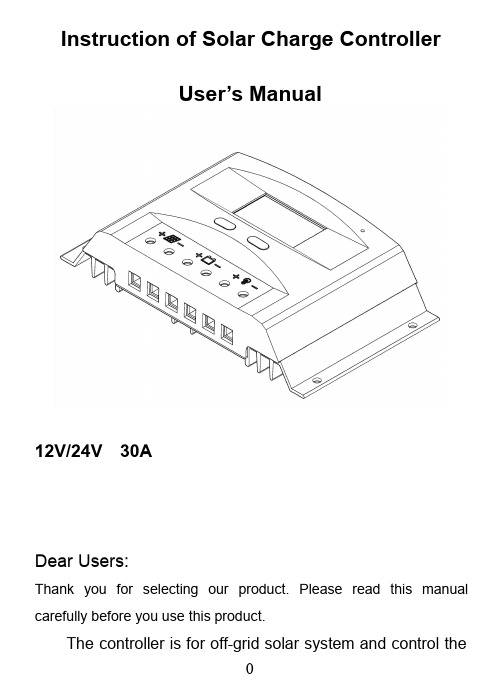
Instruction of Solar Charge ControllerUser’s Manual12V/24V30ADear Users:Thank you for selecting our product.Please read this manual carefully before you use this product.The controller is for off-grid solar system and control thecharging and discharging of the battery.Main function is protecting battery.The intelligent charging process has been optimized for long battery life and improved system performance.Major FunctionsThe features are listed below:⏹Automatic Identification System Voltage,12V/24V autorecognition.⏹Humanized LCD displaying and double button operation ofman-machine interface.⏹Completed technical data for setup and modify.⏹High efficiency intelligent PWM3stage charging⏹The load control mode can be selected,the timer function canbe reset for street light at night.⏹Discharge capacity control⏹RS485communication interface(optional)⏹Discharge Counter of Ampere Hour⏹Working Storage Function:record the total run time of system,record timers of error during running time,record times of full charged battery.⏹Reliable over voltage protection,short circuit protection,overload protection,overcharge protection,over-discharge protection.⏹Accurate temperature compensation,correcting the chargingand discharging voltage automatically,improving the battery lifetime.⏹Roundly reverse connected protection.⏹Solar Panels,Battery,Solar Charge Controller positive polesare all connected together,adopting negative MOSFET in series control circuit.Important Safety Information⏹It is better to install the controller in the room.If installed thecontroller outside,please keep the environment dry,avoid direct sunlight.⏹The controller will be hot in process of working,please keep theenvironment ventilation,away from flammable.⏹The open circuit voltage of solar panel is too high,(especially24V and48Vsystem),please take care.⏹The battery has acidic electrolysis,please put on gogglesduring installation.If you accidentally exposed to the electrolysis,please rinse with water.⏹Please avoid reverse connection or short circuit connectionunder48V system,or the product easy to destroy.⏹The battery has huge power,prohibit any conductor shortcircuit the positive and negative pole of battery.Suggest to adding a fuse between battery and controller.(Slow motiontype,the action current of the fuse should be1.5times rated current of controller.)The suggestion of using⏹The controller could detect the temperature of environment toadjust the voltage of charging,so that the controller should be closed to battery as near as possible.⏹Recommend system current density of cables less than3A/mm2.⏹Try to use multi strand copper wire in order to connecting withthe terminal firmly.Loose power connection and/or corroded wires may result in resistive connections that melt wire insulation,burn surrounding materials or even cause fire.⏹The battery should be full charged each month.Or the batterywill be destroyed.The feature of LCD graphic symbol1.The default night display of controller:When the solar panelinput voltage have been detected by controller less than sensor identification point voltage,this graphic symbol will be light.2.The default daytime display of controller:When the solar panelinput voltage have been detected by controller more than sensor identification point voltage,this graphic symbol will be light.3.The indicator of PV array parameter:When the solar panelsdata was displaying,this graphic symbol will be light.For example the voltage of solar panel.4.The indicator of battery parameter:When the battery parameterwas displaying,this graphic symbol will be light.For example the voltage of battery,temperature of battery.5.The indicator of load parameter:When the load parameter wasdisplaying,this graphic symbol will be light.6.System Voltage:When the LCD shows different system voltage,the controller will adjust the technical data automatically.7.Numerical Display Area8.Timer Setting Function9.Switch Graphic Symbol.10.Unit Symbol Value11.Warning:When there is fault,this graphic symbol will be light.12.The indicator of Load status:Load on,Load off.13.The indicator of Output power:When the load terminal haveoutput,this graphic symbol will be light.14.The indicator of capacity of battery:When the battery was indifferent capacity,the strip-type will show.15.The indicator of charge status:When the controller is charging,the symbol will be light,float charge will be flash,no charging no display.Installation InstructionsController Fixed1)The controller should be installed well-ventilated place,avoiddirect sunlight,high temperature and do not install in location where water can enter the controller.2)Please select correct screw to fix the controller on the wall orother platform.Screw M4or M5,Screw cap diameter less than 10mm.3)Please reserve enough space between the wall and controller,to allow for cooling and cable connection.4)The mounting holes distance is180mm*70mm,diameter of thehole is5mm.Controller Connection1)All terminals are in tight status after factory,in order towell connected,please loose all terminals at first.2)The following order of connection please do not free change,orcause system voltage recognition fault.3)As figure,first connected the battery to controller correct poles.In order to avoid short circuit,please screw the cable of battery to the controller in advance,then connected to battery poles secondly.If your connection is correct,the LCD displaying will show battery voltage and other technical data.If LCD no indicate,please check the fault.The length of cable between battery and controller as shorter as possible.Suggest to30CM -100CM.●If short circuit happened on the terminals ofcontroller,it will be result in fire or explode.Pleasebe careful.(We strongly suggest to connecting afuse at the battery side1.5time of rated current of controller.)●If the battery reverse connection,the output of controller alsosame with battery polarity,please do not connect any load with controller at that time,or the load and controller will be destroyed.4)As figure,connected solar panels with controller correctly,if theconnection is successful and sunshine is full,the LCD will show solar panel and an arrow from solar panel tobattery will be light.The voltage of solar panel is very high under sunshine,high voltage can cause injury or destroy controller.As figure,connected loads with controller correctly.Under48Vsystem,the reverse connection of solar panel will be destroy the solar charge controller.In order to avoiding injury from load voltage,please close to the output of controller with buttonat first,then connected the load on the controller.The controller do not offer reverse connection protection for load,so please take care,reverse connection for load will be destroy bulb.⏹About ground connection of solar systemPlease noted,this solar charge controller designed by all positive connection,all components inside the controller are positive combined together.If your solar system needs ground connection, please let positive ground connection.Warning:For some force to ground connectedsystem,such as solar communication system,portable solar system,they are negative groundconnected,at this time please do not positive connected,or can cause short circuit.Operation and Indication⏹Main interface●The controller will have1s initialization interface after electrified,then go into main interface.●If no operation at main interface inner20s,the main interfacewill be auto exchange during voltage of battery,voltage of solar panel,load current,charge current,temperature of environment eachinterface keep3s.Long press“”more than5s at main interface,it will speed auto exchange.Loose button will stop speed.●Press“”under main interface could open or close the loadoutput。
阳光电源HP系列智能太阳能充电控制器(HP2430 2440 2450 2460 HP4830 48

2. When the system is saving data, the screen may shake slightly. This is normal and the user may ignore it. 6. Safety Advice
1) When connected to a 24 V or 48V system, the solar panel terminal voltage may exceed the limit for human safety. If operation is to be performed, be sure to use insulation tools and keep your hands dry.
4
13
control (4 hours)
Light control + time control (13 hours)
Light control + time
5
14
control (5 hours)
Light control + time control (14 hours)
Light control + time
software or mobile phone APP.
12. Boasting an industrial grade design, the product can function well in various tough conditions. S lighting protection is adopted.
Battery
Quick flashing Slow
flashing 4 dashes
Battery SOC
Photonic Universe 20W 12V 太阳能充电套件说明书

20W 12V solar charging kitInstruction manualDear Customer,Thank you for selecting this Photonic Universe solar charging kit. This manual explains the installation of your solar kit and answers some frequently asked questions. Please read this manual carefully before setting up your system.Remember, all work should be carried out by an appropriately qualified person. Precautions and safety measures should be taken in all cases.Contents of the package:№Item Quantity1 20W 12V polycrystalline solar panel with 3m cable 12 5A solar charge controller 13 2m battery cable with crocodile clips (used between the controller and your battery) 14 5A fuse in a holder (installed on the battery cable) 15 Instruction manual for the solar controller 16 Instruction manual for the kit 1 Installation of the solar kit:1. Before installing the solar kit, please ensure that your 12V battery is not fully discharged. Thebattery should produce at least 8V - this is the minimum voltage required to start the solar charge controller. If your battery is fully discharged, please charge it beforehand by other means for ashort period of time.2. Connect your 12V battery to the solar charge controller using the 2m cable with crocodile clips inthe following order:−On the solar controller end, attach the bare ends of the cable using the screw terminals−On the battery end, use the crocodile clips attached to the cableThe “+” battery terminal should be connected to the “+” battery terminal of the controller, and the “-” battery terminal should be connected to the “-” battery terminal of the controller.Please note: crocodile clips are provided for temporary use only. For permanent connection, we recommend using special battery terminals or your existing battery connectors.3. Connect the solar panel to the solar charge controller: The “+” lead should be connected to the“+” solar terminal of the controller, and the “-” lead should be connected to the “-” solar terminal of the controller. Your solar kit should now start charging the battery. For maximum output, ensure that the solar panel is situated outdoors and is exposed to as much sunlight as possible, without any shading. Even a small shaded area can significantly reduce the output (e.g. leaves, treesetc.). Note: positioning the solar panel indoors behind a window is not recommended as it willreduce the output considerably.4. If required, you can connect any 12V load or appliances to the load terminals of the solarcontroller (“+” to “+”, “-”to “-”), for example 12V light bulbs. Ensure that the total current drawn by the load does not exceed 5A.Your 12V load or appliances can also be connected directly to your battery, however in this case the discharge protection feature of the solar controller will not function (the controller will not beable to automatically cut off the load when the battery is becoming over discharged).5. The solar panel and its connection box on the back are waterproof and can be used outdoors inall weather conditions. The solar controller is not waterproof and should always be used indoors.6. Please refer to the solar controller manual for information regarding operation of the controller. Photonic Universe Ltd - Bringing you the benefits of solar power -LoadPlease note that the maximum current allowed for the solar charge controller is 5A. If you are using the load terminals of the solar controller, please ensure that your load does not draw more than 5A from your battery. If you are planning on using the load terminals of the solar charge controller, it is recommended that you install a fuse into the load circuit.Do not connect an inverter or a similarly powerful appliance to the load terminals of the solar charge controller. Such appliances should be connected to your battery terminals directly.Common positive / negative ground of vehicles and boatsMost vehicles (including motorhomes and caravans) and boats typically have a common ground connection, where the vehicle body (or boat hull) is used as a shared connection point by the engine, generator, battery, lights and other system components. When installing the solar kit on such vehicles / boats, please pay attention to the following recommendations:- To avoid any short circuits or conflicts between your vehicle / boat system and the solar kit system, you should never ground the solar panel (i.e. never connect it to your vehicle body / boat hull). The solar panel cable should be fully electrically isolated from your vehicle body / boat hull and should be connected directly to the solar controller.- Similarly, if you are using the load terminals of the solar controller, your load should be fully isolated from the vehicle body / boat hull and should be connected directly to the solar controller. If required, your battery can remain connected to the vehicle / boat system when the solar charging kit is connected to it (in parallel). It should not cause any interference with the solar controller unless the battery is being charged by the engine. Engine charging may cause the following to occur: - The voltage of the battery circuit will increase due to the alternator charging your battery- The solar controller will treat this as if the battery were fully charged and will cut the solar panel off temporarily to prevent overcharging of your battery.- When engine charging ceases, the solar kit will resume charging automatically.Frequently asked questionsQ. What type of batteries can be used with this kit?A. Any sealed, gel or flooded 12V lead acid battery with a capacity greater than 8Ah.Q. Can this kit charge a 24V battery?A. No, this kit is designed for charging a 12V battery.Q. Can the kit charge two 12V batteries connected in parallel?A. It’s possible but only for batteries always wired together as a single 12V battery bank (batteries should be the same type and capacity).Q. Is there any risk that the solar kit will overcharge my battery?A. The solar charge controller has a built-in overcharge protection – it will ensure that your battery is not overcharged.Q. Can I leave the solar kit connected to the battery overnight? I heard that power might flow back into the solar panel and discharge the battery.A. The solar charge controller will prevent any reverse current flow, so your battery will not get discharged during the night.Q. If I want to disconnect the system, how do I do this?A. Disconnection should follow the reverse order to connection. The solar panel should be disconnected from the charge controller first, and then the charge controller should be disconnected from the battery. Photonic Universe Ltd - Bringing you the benefits of solar power -Q. If I disconnect the solar panel from the charge controller, can I leave the controller connected to the battery?A. Yes, the solar charge controller can remain connected to the battery without the solar panel.Q. I need to shorten / extend the solar panel cable. Is this possible?A. Yes, it’s possible. If you are extending the solar panel cable please make sure you use cable with the same cross section and your connections are secure (soldering is recommended) and well insulated.Q. Can the solar kit be used for positive / negative ground vehicles / boats?A. Yes, the solar kit can be used in both positive and negative ground vehicles and boats. As per the above note, please make sure that the solar panel (and load if you are using the load terminals of the solar controller) are fully electrically isolated from the body of your vehicle / boat hull.Q. What is the difference between polycrystalline and monocrystalline solar panels?A. The difference relates to the process of the solar cell manufacturing rather than product characteristics. Monocrystalline solar panels can use the space slightly more efficiently, but polycrystalline solar panels perform slightly better in hot climates. The difference is not significant.Q. I want to have more solar power and charge my battery faster – can I upgrade the solar kit?A. You can easily upgrade this kit from 20W to 40W by adding a similar 20W solar panel to the same charge controller. The output will double and the charging time will halve. See Appendix for more details. Q. Do I need to clean my solar panel?A. Yes. Regular cleaning increases energy yield. Always remember that any shading will reduce the output of the solar panel.TroubleshootingTypically, a problem occurs when the controller loses connection to your battery (due to a blown fuse, poor connections, a discharged battery etc). In such circumstances, you may notice fast flashing of all the lights on the controller (if the solar panel is still connected) or no lights at all. To rectify the problem, firstly disconnect the solar panel from the controller, then disconnect the battery and repair the connections / re-charge the battery. Secondly, reconnect the battery only and ensure that you see the battery light on the controller. Thirdly, reconnect the solar panel as per the instructions above.Other potential troubleshooting solutions are provided below:•Ensure your battery generates at least 8V. Disconnect any load which may be drawing power from your battery (also disconnect your battery from the system of your vehicle / boat).•Check all connections to ensure they are secure and clean.•Check the polarity of the battery connections and solar panel connections.•Ensure the solar panel is exposed to sufficient light – ideally positioned to face the sun directly.•For more information, refer to the Troubleshooting section of the solar controller manual. WarrantyThis product is covered by a 1 year warranty provided by Photonic Universe Ltd. We will repair or replace any products with defects at our discretion.DisclaimerWorking with electricity and batteries can be dangerous. The information provided inthis manual is for general guidance only. All work should follow the safety standardsand should be carried out by an appropriately qualified person.Photonic Universe Ltd is not responsible for any damage or injury caused byinappropriate installation or use of the product.Photonic Universe Ltd - Bringing you the benefits of solar power -Appendix 1.Information on solar kit upgrades YOU CAN UPGRADE YOUR SOLAR KIT FROM 20W TO 40W AT ANY TIMEDid you know that you can easily double the power of your solar kit from 20W to 40W and charge your battery twice as fast? Just add a similar 20W solar panel to your solar kit:+Connect the second 20W solar panel to the same solar terminals of the controller, in parallel with your existing 20W solar panel (connecting “+” to “+”, “-” to “-”) –it’s that simple. The output of your solar kit will double and the charging time will halve.20W solar panels are available in our online shop: You can also order over the phone on: ***********(int. +44 203 150 1111)If you want to upgrade your kit by more than 20W, or have any other questions, please do not hesitate to email us at ************************* or call us on 020 3150 1111 (international +44 203 150 1111).Photonic Universe Ltd - Bringing you the benefits of solar power -。
solarcell
Solar CellIntroductionA solar cell, also known as a photovoltaic cell, is an electrical device that converts sunlight into electricity by the photovoltaic effect. It is a key component in solar panels and plays a crucial role in harnessing solar energy. Solar cells are widely used to generate clean and renewable energy for various applications including residential, commercial, and industrial sectors.Working PrincipleSolar cells are based on the principle of the photovoltaic effect. This effect occurs when certain materials, known as semiconductors, absorb photons from sunlight, which then excite the electrons within the material. The excited electrons create an electric current when they flow through the material. This current can be harnessed and used as a source of electrical energy.Types of Solar CellsThere are several types of solar cells that vary in their material composition and efficiency. The most common types include:1.Monocrystalline Silicon Solar Cells:–These solar cells are made from a single crystal structure, resulting in high efficiency.–They have a uniform dark color and are easily recognizable by their rounded edges.–Monocrystalline solar cells tend to be more expensive due to the manufacturing process.2.Polycrystalline (Multicrystalline) Silicon Solar Cells:–These solar cells are made from multiple crystal structures, which makes them less efficient compared to monocrystalline cells.–They have a bluish color and a granular appearance.–Polycrystalline solar cells are more cost-effective compared to monocrystalline cells.3.Thin-Film Solar Cells:–These solar cells are made by depositing a thin layer of semiconductor material onto a substrate.–Thin-film solar cells are flexible and lightweight, making them suitable for various applications.–They have a lower efficiency compared to crystalline silicon solar cells but are cheaper toproduce.anic Solar Cells:–Also known as organic photovoltaic cells (OPV), these solar cells use organic materials as thesemiconductor.–Organic solar cells have the advantage of being printable and can be manufactured using low-costprocesses.–However, their efficiency is currently lower compared to other types of solar cells.Manufacturing ProcessThe manufacturing process of solar cells involves several steps, including:1.Silicon Production:–The primary material used in most solar cells is silicon, which is obtained through a complex process.–Pure silicon is extracted from silica (SiO2), which is then refined and purified to reach the desiredlevel of purity.2.Wafer Production:–The purified silicon is transformed into solid blocks called ingots.–The ingots are then sliced into thin wafers using a diamond saw.–These wafers serve as the base for the solar cells.3.Doping:–Doping is a process in which impurities are added to the silicon wafer to create a p-n junction, which is necessary for the photovoltaic effect.–The addition of phosphorous or boron atoms introduces extra electrons or electron holes into the silicon structure, respectively.4.Formation of Layers:–Several layers are formed on the surface of the silicon wafer to enhance the solar cell’s efficiency.–These layers include anti-reflective coatings and metal contacts.5.Assembly into Modules:–The individual solar cells are interconnected and assembled into modules or panels.–The modules are then encapsulated to protect the solar cells from environmental factors.Efficiency and LimitationsThe efficiency of a solar cell refers to the percentage of sunlight converted into electrical energy. The efficiency varies depending on the type of solar cell and its manufacturing process. Currently, the most efficient solar cells on the market can achieve efficiencies of over 20%.Solar cells, however, have certain limitations, including:1.Efficiency Drop with Temperature:–Solar cells become less efficient as their temperature increases.–High temperatures can reduce the voltage and current output, lowering the overall performance.2.Dependency on Sunlight:–Solar cells rely on sunlight and their efficiency decreases in cloudy or shaded conditions.–The placement and orientation of solar panels play a crucial role in maximizing energy output.3.Cost:–The initial cost of solar cell production is relatively high, although it has been decreasing inrecent years.–The cost of solar cells is influenced by factors such as material type, manufacturing process, andmarket demand.ApplicationsSolar cells have a wide range of applications, including:1.Residential Solar Power Systems:–Solar panels installed on rooftops can generate electricity for residential use.–Excess energy can be fed back into the grid or stored in batteries for later use.mercial and Industrial Solar Power Systems:–Large-scale solar power plants generate electricity for commercial and industrial applications.–These systems can supply power to factories, offices, and other commercial buildings.3.Portable Solar Chargers:–Solar cells can be used to power handheld devices such as smartphones, tablets, and laptops.–Portable solar chargers provide a convenient and renewable source of energy for outdoor activities.4.Solar Lighting:–Solar cells are used in outdoor lighting systems, including streetlights, garden lights, and pathwaylights.–These systems eliminate the need fortraditional electrical wiring and reduce energyconsumption.5.Space Applications:–Solar cells are extensively used in spaceapplications such as satellites and spacecraft.–In space, solar cells provide the necessary power for various onboard systems and equipment.ConclusionSolar cells are vital components in the generation of clean and renewable energy. They utilize the photovoltaic effect to convert sunlight into electricity, making them an environmentally friendly alternative to traditional energy sources. With advancements in technology and decreasing costs, solar cells are becoming increasingly popular and are expected to play a significant role in meeting our future energy needs.。
太阳能发电Solar power英文翻译

Solar powerAlong with economical development, society's progress, the people to the energy proposed the more and more high request, seeks the new energy to become the urgent topic which the current humanity faces.The existing energy mainly has 3 kinds, namely thermal power, water and electricity。
Water and electricity to a large number of submerged land, that could lead to ecological destruction and the collapse of large reservoirs once the collapse, the consequences would be disastrous. In addition, a country's water resources is also limited, but also by the impact of the season. Nuclear power under normal circumstances is clean, but unlikely event of a nuclear leak, the consequences are terrible same. The former Soviet Union, the Chernobyl nuclear power plant accident, has nine million people have been varying degrees of damage, and this impact has not been terminatedThese are compelling people to go looking for new energy. New energy to simultaneously satisfy two conditions: First, not depletion of rich; II are safe, clean, not a threat to humans and damage the environment. Currently found in the main, two new energy, solar energy first, and second, the fuel cell. In addition, wind power could also be regarded as supporting the new energy. Among them, the best new energy sources are able to Dayang..Solar power generation are the best new energyRadiation in the Earth's solar energy is very strong, about 40 minutes exposure in the Earth's solar energy, would be sufficient for the global human energy consumption for one year. It can be said that solar energy is truly inexhaustible source of energy. And solar power is absolutely clean, no pollution. So are ideal for solar power as energy。
Blue Sky Energy Solar Boost 3024i 产品说明书
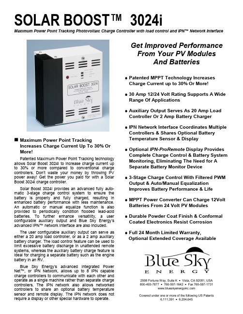
Maximum Power Point TrackingIncreases Charge Current Up To 30% Or More!Patented Maximum Power Point Tracking technology allows Solar Boost 3024i to increase charge current up to 30% or more compared to conventional charge controllers. Don’t waste your money by throwing PV power away! Get the power you paid for with a Solar Boost 3024i charge controller.Solar Boost 3024i provides an advanced fully auto-matic 3-stage charge control system to ensure the battery is properly and fully charged, resulting in enhanced battery performance with less maintenance.An automatic or manual equalize function is also provided to periodically condition flooded lead-acid batteries. To further enhance versatility, a user configurable auxiliary output and Blue Sky Energy’s advanced IPN™ network interface are also included.The user configurable auxiliary output can serve as either a 20 amp load controller, or as a 2 amp auxiliary battery charger. The load control feature can be used to limit excessive battery discharge in unattended remote systems, whereas the auxiliary battery charge feature is ideal for charging a separate battery such as the engine battery in an RV.Blue Sky Energy’s advanced Integrated Power Net™, or IPN Network, allows up to 8 IPN capable charge controllers to communicate with each other and operate as a single machine rather than separate charge controllers. The IPN network also allows networked controllers to share an optional battery temperature sensor and remote display. The IPN network does not require a display or other special hardware to operate.SOLAR BOOST™ 3024iMaximum Power Point Tracking Photovoltaic Charge Controller with load control and IPN™ Network InterfaceGet Improved Performance From Your PV ModulesAnd Batteries•Patented MPPT Technology Increases Charge Current up to 30% Or More!•30 Amp 12/24 Volt Rating Supports A Wide Range Of Applications•Auxiliary Output Serves As 20 Amp Load Controller Or 2 Amp Battery Charger •IPN Network Interface Coordinates Multiple Controllers & Shares Optional Battery Temperature Sensor & Display•Optional IPN-ProRemote Display Provides Complete Charge Control & Battery System Monitoring, Eliminating The Need for A Separate Battery Monitor Device•3-Stage Charge Control With Filtered PWM Output & Auto/Manual Equalization Improves Battery Performance & Life •MPPT Power Converter Can Charge 12Volt Batteries From 24 Volt PV Modules •Durable Powder Coat Finish & Conformal Coated Electronics Resist Corrosion •Full 24 Month Limited Warranty,Optional Extended Coverage Available2598 Fortune Way, Suite K • Vista, CA 92081, USA 800-493-7877 • 760-597-1642 • Fax 760-597-1731 Covered under one or more of the following US Patents6,111,391 • 6,204,645How Do Solar Boost Charge Controllers Increase Charge Current?Solar Boost controllers increase charge current by operating the PV module in a manner that allows the module to produce all the power it is capable of. A con-ventional charge controller simply connects the module to the battery when the battery is discharged. When the 75W module in this example is connected directly to a battery charging at 12 volts its power production is artificially limited to about 53 watts. This wastes a whopping 22 watts or nearly 30% of the available power!Patented MPPT technology used in Solar Boost controllers operates in a very different fashion. The Solar Boost controller continually calculates the module’s maximum power voltage, in this case 17 volts.It then operates the module at its maximum power voltage to extract maximum power. The higher power extracted from the module is then provided to the battery in the form of increased charge current. In conditions where extra PV power is not available, Solar Boost controllers will operate as a conventional controller with very low voltage drop.Typical 75W PV Module Performance25°C Cell • 1000W/m2The actual charge current increase you will see varies primarily with module temperature and battery voltage. In comfortable temperatures, current increase typically varies between 10 to 25%, with 30% or more easily achieved with a discharged battery and cooler temperatures. What you can be sure of is that Solar Boost charge controllers will deliver the highest charge current possible for a given set of operating conditions.SPECIFICATIONS Solar Boost 3024iOutput Current Rating 30 Amp maximum, automatic 30 Amp current limitNominal Battery Voltage12 / 24VDC PV Input Voltage 57VDC maximumPower Consumption 0.35W Typical standby • 1.0W Typical charge onCharge Algorithm 3-stage Bulk/Acceptance/Float (Full charge can be based on net charge current matched to battery amp-hours ➁)Acceptance Voltage14.4VDC (range 14.0 – 14.8VDC ➀, 10.0 – 40.0VDC ➁)Float Voltage 13.4VDC (range 13.2 – 13.8VDC ➀, 10.0 – 40.0VDC ➁)Equalization Voltage 15.4VDC (range 10.0 – 40.0VDC ➁) • automatic or manual operationSingle output field configurable as either: 20 Amp load controller –or– 2 Amp auxiliary battery charger2 Amp typical, same charge voltage as primary batteryAuxiliary Output Function • Aux. Battery charge • Load Control 20 Amp maximum; ON @ ≥12.6VDC / OFF @ ≤11.5VDC (Range 10.0 – 40.0VDC ➁, or net battery amp-hours ➁)Temperature Compensation Optional temperature sensor adjusts charge voltage setpoints based on measured battery temperature,-5.00 mV/°C/cell correction factor (Range -0.00 – -8.00 mV/°C/cell ➁) • sensor range -60 – +80°CPower Conversion Efficiency97% @ 28 Volt 24 Amp OutputCabinet Dimensions 6⅞”H x 6⅝”W x 3⅜”D (17.4cm x 16.8cm x 8.59cm)Analog Input Accuracy / Range Battery & Aux. Battery voltmeters, 40.0VDC ±0.50% FS • PV voltmeter, 60.0VDC ±0.50% FSInput/Output ammeters 35.0A ±0.50% FSCommunicationBlue Sky Energy’s proprietary IPN Network interface. Allows up to 8 IPN capable controllers to set up and operate as a single machine, share a common battery temperature sensor, and share an IPN-Remote or IPN-ProRemote display.Simple twisted pair cable interface with no special communication hardware required. RS-232 interface for remotecomputer control and display available through the IPN-ProRemote with -232 option.Environmental-40 – +40°C, 10 – 90% RH non-condensingAs a part of our continuous improvement process➀ SB3024i alone, voltages double for 24V battery specifications are subject to change without prior notice ➁With IPN-ProRemoteAvailable From: Part Numbers & Shipping WeightSolar Boost 3024i ...............SB3024i.........5 lbs....11kg IPN-ProRemote with shunt..IPNPRO-S...1.8 lbs..3.9kg IPN-ProRemote w/o shunt...IPNPRO.........1 lbs...2.2kg 500A / 50mV current shunt..506-0003-01...1 lbs...2.2kg IPN-Remote........................IPNREM.........1 lbs...2.2kg Battery Temp. sensor, 20’...930-0022-20...1 lbs...2.2kg© Blue Sky Energy, Inc. 20042598 Fortune Way, Suite K • Vista, CA 92081, USA 800-493-7877 • 760-597-1642 • Fax 760-597-1731440-0014 A。