STBB068中文资料
泊声E68产品说明书
附件一 : FM 电台接收信号增强的几种方法
附件二: FM 天线安装示意图
附件三: MP3 使用注意事项
附件四:安装布线说明
1. backaudio 泊声简介
backaudio 泊声是业界领先的家庭背景音乐品牌,采用美国顶级音频工程设计及 DSP 数 字信号处理技术,系统操作灵活方便,HI-FI 级立体声音质,声音均匀柔和;泊声同时开创 性地提出了中央智能主机的概念,集成了功放阵列和先进的控制系统,拥有该领域多项专利; 凭借优异稳定的性能、卓越的人性化设计理念及优质的服务,泊声家庭背景音乐系统深受顾 客的喜爱和消费者的广泛好评。
2.3.1.产品特点.................................................................................................................. 2 2.4. 标准控制面板使用说明 .................................................................................................. 4 3. 系统安装说明.............................................................................................................................. 4 3.1. 喇叭选型及安装 .............................................................................................................. 4
亿佰特WiFi模组选型指南以及WiFi模块应用方案详解
亿佰特WiFi模块选型指南及WiFi模块物联网应用案例成都亿百特电子科技有限公司WiFi类模组分别采用UART 、SDIO、USB三种不同接口,内置IEEE802.11协议栈以及 TCP/IP 协议栈,能够实现用户串口数据到无线网络之间的转换。
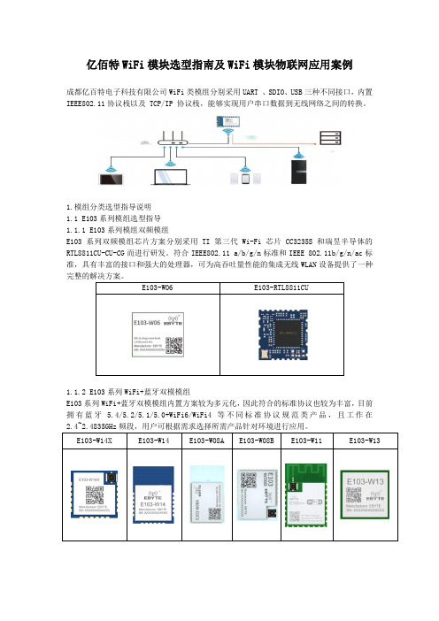
1.模组分类选型指导说明1.1 E103系列模组选型指导1.1.1 E103系列模组双频模组E103系列双频模组芯片方案分别采用TI第三代Wi-Fi芯片CC3235S和瑞昱半导体的RTL8811CU-CU-CG而进行研发。
符合IEEE802.11 a/b/g/n标准和IEEE 802.11b/g/n/ac标准,具有丰富的接口和强大的处理器,可为高吞吐量性能的集成无线WLAN设备提供了一种E103-W06 E103-RTL8811CU1.1.2 E103系列WiFi+蓝牙双模模组E103系列WiFi+蓝牙双模模组内置方案较为多元化,因此符合的标准协议也较为丰富,目前拥有蓝牙 5.4/5.2/5.1/5.0+WiFi6/WiFi4等不同标准协议规范类产品,且工作在1.1.3 E103系列超低功耗WiFi模组E103系列低功耗WiFi模组工作在2.4~2.4835GHz 频段,符合IEEE 802.11b/g/n协议标准。
模块集成了透传功能,即拿即用,支持串口 AT 指令集用户通过串口即可使用网络访问的功能,广泛应用于穿戴设备、家庭自动化、家庭安防、个人保健、智能家电、配饰与遥控器、1.1.4 E103系列WiFi路由模组E103系列WiFi路由模组目前拥有两款产品,分别为E103-W20(7688)和 E103-W20(7628)。
该类模块是基于联发科 MT7688AN及 MT7628AN为核心的低成本低功耗的物联网模块。
模块引出了 MT7688AN /MT7628AN的所有接口,支持 OpenWrt 操作系统及自定义开发,具有丰富的接口和强大的处理器,可以广泛的应用于智能设备或云服务应用等,并可以自由进行1.1.5 E103系列通用型模组E103系列通用型模组不仅具有丰富的外设接口,还拥有强大的神经网络运算能力和信号处理能力,成本低,且适用于AloT 领域的多种应用场景,例如唤醒词检测和语音命令识别、E103-RTL8189 E103-W05 E103-W01-IPX E103-W01 E103-W101.1.6 E103系列WiFi mesh模组在 EBYTE 的方案中,我们公司支持WIFI Mesh支持有路由组网和无路由组网的模块为E103-W07,E103-W07是一套建立在Wi-Fi协议之上的网络协议。
BL702 704 706 无线通信芯片数据手册说明书
BL702/704/706数据手册版本:2.1版权@2021Features•无线–2.4GHz射频收发器–蓝牙规范v5.0–蓝牙低功耗1Mbps和2Mbps–蓝牙®Long Range Coded500Kbps和125Kbps–Zigbee3.0,基本设备行为,Core Stack R21,绿色能源标准–IEEE802.15.4MAC/PHY–支持BLE/zigbee共存–集成balun,PA/LNA•MCU子系统–带FPU(浮点单元)的32位RISC CPU–一级缓存–1个RTC计时器,最长计数周期为1年–2个32位通用定时器–8个DMA通道–CPU频率可配置为1MHz至144MHz–JTAG开发支持–XIP QSPI Flash/pSRAM具备硬件解密功能•内存–132KB RAM–192KB ROM–1Kb eFuse–嵌入式Flash闪存(选配)–嵌入式pSRAM(BL704/BL706,选配)•安全机制–安全启动–安全调试端口–QSPI Flash即时AES解密(OTFAD)-AES-128和CTR+模式–支持AES128/192/256位加密引擎–支持MD5,SHA-1/224/256/384/512–真实随机数发生器(TRNG)–公钥加速器(PKA)•外设–USB2.0FS(全速)设备接口–红外遥控接口–1个SPI主/从机–2个UART支持ISO17987(本地互连网络)–1个I2C主机–1个I2S主/从–5个PWM通道–正交解码器–按键扫描矩阵接口–12位通用ADC–10位通用DAC–被动红外(PIR)检测–以太网RMII接口(BL704/BL706)–摄像头接口(BL706)–15(BL702)/23(BL704)/31(BL706)个GPIO(功能可配置)•电源管理模式–CPU正常运作BL702/704/706数据手册2/43@2021Bouffalo Lab–空闲模式–睡眠模式(可配置不同区域)–休眠模式–电源关闭模式–主动接收–主动发送•时钟架构–外部主时钟XTAL32MHz–外部低功耗和RTC时钟XTAL32/32.768kHz –内部RC32kHz振荡器–内部RC32MHz振荡器–内部系统PLL–内部音频PLLContents1概述 (9)2功能描述 (10)2.1CPU (11)2.2缓存 (11)2.3内存 (11)2.4DMA控制器 (11)2.5总线结构 (11)2.6中断 (13)2.7启动选项 (13)2.8电源管理单元 (13)2.9时钟架构 (13)2.10外设 (14)2.10.1GPIO (15)2.10.2UART (15)2.10.3SPI (15)2.10.4I2C (15)2.10.5I2S (15)2.10.6TIMER (15)2.10.7PWM (16)2.10.8IR(IR-remote) (16)2.10.9USB2.0(Full Speed) (16)2.10.10EMAC (16)2.10.11QDEC (16)2.10.12ADC (16)2.10.13DAC (17)2.10.14调试接口 (17)BL702/704/706数据手册3管脚定义 (18)4电气特性 (26)4.1绝对最大额定值 (26)4.2运行条件 (26)4.2.1电源特性 (27)4.2.2温度特性 (27)4.2.3通用工作条件 (27)4.2.4GPADC特性 (27)5产品使用 (30)5.1湿敏等级(MSL) (30)5.2静电放电(ESD) (31)5.3回流焊接曲线(Reflow Profile) (31)6参考设计 (33)7封装信息QFN32 (34)8封装信息QFN40 (36)9封装信息QFN48 (38)10标志定义 (40)11订购信息 (41)12版本信息 (43)List of Figures1.1功能框图 (9)2.1系统框图 (10)2.2时钟框图 (14)3.1BL702管脚布局 (18)3.2BL704管脚布局 (19)3.3BL706管脚布局 (20)5.1Classification Profile(Not to scale) (31)6.1参考设计 (33)7.1QFN32封装图 (34)8.1QFN40封装图 (36)9.1QFN48封装图 (38)10.1标志定义 (40)11.1型号命名 (41)List of Tables2.1总线连接 (11)2.2地址映像 (12)2.2地址映像 (13)3.1管脚定义 (20)3.1管脚定义 (21)3.1管脚定义 (22)3.2GPIO Muxed Pins (23)3.2GPIO Muxed Pins (24)3.3UART信号映射表(Default) (25)3.4UART信号映射表(Example) (25)4.1电源的绝对最大额定值 (26)4.2建议电源值范围 (27)4.3建议温度值范围 (27)4.4一般操作条件 (27)4.5GPADC特性 (28)4.6ADC electrical characteristic (29)5.1Reference Conditions for Drying Mounted or Unmounted SMD Packages(User Bake:Floor life be-gins counting at time=0after bake) (30)5.2Classification Reflow Profiles (32)7.1尺寸说明(测量单位:毫米) (34)7.1尺寸说明(测量单位:毫米) (35)8.1尺寸说明(测量单位:毫米) (36)8.1尺寸说明(测量单位:毫米) (37)9.1尺寸说明(测量单位:毫米) (38)9.1尺寸说明(测量单位:毫米) (39)11.1订购选项 (42)12.1修改记录 (43)1概述BL702/BL704/BL706是用于物联网应用的高度集成的BLE和zigbee组合芯片组。
石科低制造墙牌系列产品说明书

Stonco_LowProfileWall_SpecSheet 08/21 page 1 of 2Ordering guideExample: PW-50-NW-G1-8-BZLuminairePWWattageLED Color – GenerationNW-G1Voltage8FinishBZPW Low Profile Wall15 15W 30 30W 50 50WNW-G1 Neutral White, 4000K, 80 CRI, Generation 18120-277 VoltsBZ BronzeHousingDie-cast aluminum housing with UV stabilized polycarbonate lens mounted with stainless steel hardware.IP RatingLED light engine is weather proof rated IP65.ElectricalElectrical Driver efficiency (>90% at full load). Available in 120-277V. IP65 compliant driver. RoHS compliant. Surge protector standard. 10KA per ANSI/IEEE C62.41.2.LED Board and Array24, 48, and 80 LEDs. Color temperature4000K, +/- 500K. Minimum CRI of 80. Aluminum metal clad board with midpower LED chips.Optical SystemDirect mid-power LED distribution with white reflective plate. Optical system is designed for zero uplight. Light engine is weather protected with silicone sealed clear glass.MountingMounts to standard 3 ½” to 4” square and octagonal or 4 inch round electrical junction boxes.Energy Saving BenefitsSystem efficacy up to 110lms/W withsignificant energy savings over Pulse Start Metal Halide luminaires.ListingsUL/cUL listed to the UL 1598 standard,suitable for Wet Locations. Suitable for use in ambient from -30° to 40°C (-22°to 104°F). Not all product variations listed on this page are DLC qualified. To ensure that an specific model is qualified, visit /searchFinishEach luminaire receives a fade andabrasion resistant, electrostatically applied, thermally cured, triglycidal isocyanurate (TGIC) textured polyester powdercoat finish. Standard color isbronze (BZ).Limited WarrantyLuminaires are all covered by a 5-yearlimited warranty. See /warranties for details.Specifications Stonco Low profile wall mount features a discreet design that will complement any building exterior. Three sizes are available in 15, 30 and 50W output to accommodate multiple mounting heights. Low Profile Wall delivers up to 110 lumens per watt for excellent energy savings over HID.Dimensions1. Predicted performance derived from LED manufacturer's data and engineering design estimates, based on IESNA LM-80 methodology. Actual experience may vary due to field application conditions.2. L70 is the predicted time when LED performance depreciates to 70% of initial lumen output.3. Calculated per IESNA TM 21-11. Published L 70 hours limited to 6 times actual LED test hoursPredicted Lumen Depreciation Datathreaded side holes with plugs, 1 each sidethreaded side holes with plugs, 1 each sidethreaded side holes with plugs, 1 each sidePW15PW30PW501. Wattage and lumen output may vary by due to LED manufacturer forward volt specification and ambient temperature. Wattage shown is average for 120V through 277V input. Measured wattage may vary due to variation in input voltage.2. Lumen values based on photometric tests performed in compliance with IESNA LM-79. Contact *************************************************************************LED Wattage and Lumen ValuesPredicted performance derived from LED manufacturer’s data and engineering design estimates, based on IESNA LM-80 methodology. Actual experience may vary due to field application conditions.L70 is the predicted time when LED performance depreciates to 70% of initial lumen output. Calculated per IESNA TM21-11. Published L70 hours limited to 6 times actual LED test hours.PW LED Low profile wall15W, 30W, and 50WFILENAME HERE XX/2019page 2 of 2© 2021 Signify Holding. All rights reserved. The information provided herein is subject to change, without notice. Signify does not give any representation or warranty as to the accuracy or completeness of the information included herein and shall not be liable for any action in reliance thereon. The information presented in this document is not intended as any commercial offer and does not form part of any quotation or contract, unless otherwise agreed by Signify.Stonco_LowProfileWall_SpecSheet 08/21 page 2 of 2 Signify North America Corporation200 Franklin Square Drive, Somerset, NJ 08873Telephone 855-486-2216Signify Canada Ltd. 281 Hillmount Road,Markham, ON, Canada L6C 2S3 Telephone 800-668-9008All trademarks are owned by Signify Holding or their respective owners.。
stb工具
stb工具STB工具是一种被广泛应用于电视机顶盒和其他多媒体设备的关键软件工具。
STB,即Set-Top Box,是一种装置,用于接收电视信号并将其转换为可供电视机显示的图像。
STB工具的作用是管理和控制STB设备的各种功能,包括信号接收、媒体播放、应用运行等。
STB工具的功能非常丰富,它可以接收来自有线电视、卫星电视、数字电视等各种信号源的节目,并通过解码和解析将其转换为可供电视机显示的图像。
同时,STB工具还支持多种媒体格式的播放,如视频、音频、图片等,用户可以通过STB工具观看电影、听音乐、查看照片等。
除了基本的信号接收和媒体播放功能,STB工具还具备丰富的应用扩展功能。
用户可以通过STB工具安装和运行各种应用程序,如电子商务应用、游戏应用、社交媒体应用等。
这些应用可以通过网络连接进行更新和下载,从而实现STB设备的功能扩展和增强。
STB工具还具备强大的操作和控制功能,用户可以通过遥控器、键盘、鼠标等外部设备对STB设备进行操作和控制。
例如,用户可以通过遥控器选择和切换频道、调整音量、调节画面质量等。
同时,用户还可以通过外部设备进行搜索、输入文字、浏览网页等操作,以实现更加便捷和智能的使用体验。
在STB工具的开发和应用中,软件平台起着至关重要的作用。
常见的STB工具软件平台包括Android、Linux、Windows等。
不同的软件平台提供了不同的开发环境和工具链,开发人员可以根据需求选择适合的平台进行开发。
同时,软件平台还决定了STB工具的兼容性和性能表现,因此选择合适的软件平台对于STB工具的稳定性和性能都至关重要。
在STB工具的开发过程中,还需要考虑到设备硬件的特性和限制。
STB设备通常具有较小的存储空间和有限的处理能力,因此在开发过程中需要对软件进行优化,以提高性能和节省资源。
同时,还需要考虑到STB设备的兼容性和稳定性,确保软件在不同型号的设备上都能正常运行。
总结而言,STB工具是一种关键的软件工具,用于管理和控制电视机顶盒和其他多媒体设备的功能。
博布里克洗手间设备产品技术数据表说明书

The illustrations and descriptions herein are applicable to production as of the date of this T echnical Data Sheet. Revised 9/07 Printed in U.S.A. The manufacturer reserves the right to, and does from time to time, make changes and improvements in designs and dimensions. © 2007 by Bobrick Washroom Equipment, Inc.The illustrations and descriptions herein are applicable to production as of the date of this T echnical Data Sheet.1040 Revised 9/07 Printed in U.S.A.The manufacturer reserves the right to, and does from time to time, make changes and improvements in designs and dimensions.© 2007 by Bobrick Washroom Equipment, Inc.maTerialS:Stiles — 1'' (25mm) finished thickness: 3-ply, 45-lb (20.4-kg) density, resin-impregnated particle board is bonded to each side of 11-gauge (3.2mm) sheet steel that serves as reinforcing core; surfaces and edges are .050'' (1.3mm) thick, high-pressure plastic laminate with colored face sheets and matte finish. Leveling device: 3/8'' x 7/8'' (10 x 22mm) steel bar is welded to sheet-steel core of stile, forming a single structural unit; furnished with 3/8'' (10mm) diameter threaded rods, hex nuts, lock washers, flat washers, expansion shields, and shoe retainers. Shoe: 18-8 S, type-304, 22-gauge (0.8mm) stainless steel with satin finish; 4'' (102mm) high.Panels and doors — 1'' (25mm) finished thickness: 3-ply, 45-lb (20.4-kg) density, resin-impregnated particle board; surfaces and edges are .050'' (1.3mm) thick, high-pressure plastic laminate with colored face sheets and matte finish.Posts (for 1043 Series screens only) — 1-1/4'' (32mm) square tubing; 18-8 S, type-304, 18-gauge (1.2mm) stainless steel with satin finish. Floor and ceiling connections are constructed of 18-8 S, type-304, heavy-gauge stainless steel. Furnished in 10-ft (305-cm) lengths; to be cut in field to job specifications.Headrail (for 1042 Series only) — Extruded anodized aluminum with satin finish. Enclosed construction with sloping top. Face has raised grip-resistant edge.Designer's Notes: Headrails with integral curtain tracks and hooks are available for compartments without doors. Vinyl curtains are available as an optional ac-cessory. Benches are available as an optional accessory for dressing compartments: 1'' (25mm) thick laminated plastic, 10'' (25cm) deep, 18'' or 24'' (46 or 61cm) wide; furnished with two stainless steel support brackets.Wall Posts — 1" x 1-1/2" (25 x 38mm) tubing. 18-8 S, type-304, 16-gauge (1.6mm) stainless steel with satin finish. 58" (147cm) high, pre-drilled for door hard-ware.Commercial Hardware (standard) — Hinges, door latches, door keepers, clothes hooks, and mounting brackets are constructed of 18-8 S, type-304, heavy-gauge stainless steel with satin finish. Threaded inserts are factory installed for securing hinges on inswing doors and furnished for outswing doors. T-nuts are factory installed for securing door latch. Theft-resistant, stainless steel pin-head, torx screws are furnished for door hardware and all mounting brackets. Black rubber bumper on the door latch serves as door bumper for inswing door. Balanced hinge is adjustable to hold door of unoccupied toilet compartment partially open or fully closed. Toilet compartment door is locked from inside by sliding door latch into keeper. A locked compartment may be opened from outside by lifting door to disengage latch from keeper. Track of door latch prevents inswing door from swinging out beyond stile; on outswing door, the door keeper prevents it from swinging in beyond stile.Continuous Hardware (.65 option) — Hinges, door latches, door keepers, clothes hook, U-channels, door stop plates and angle brackets are constructed of 18-8 S, type-304, heavy-gauge stainless steel with satin finish; one-piece, full-height hinge is 16 gauge (1.6mm); one-piece door keepers shall be is 11 gauge (3.2mm); one-piece full-height U-channels and angle brackets are 18 gauge (1.2mm). U-channels secure panels to stiles, and angle brackets secure panels and stiles to walls. Door latch slides on a shock-resistant nylon track. A locked compartment may be opened from outside by lifting door to disengage latch from keeper. Two doorstops prevent door from being kicked out by vandals. Theft-resistant, stainless steel pin-head, torx screws are furnished for door hardware, U-channels, and angle brackets. Doors are equipped with a self-closing hinge. Threaded inserts are factory installed to secure door hinge, latch, and doorstops. To specify continuous hardware, add suffix .65 to series number. Example: specify 1042.65 for overhead-braced partitions furnished with continuous hardware, including factory-installed threaded inserts for door hardware attachment.inSTallaTion:Bobrick installation instructions are packed with each shipment and are available also in advance on request.notes:1. Where water from showers or hose-down cleaning comes in contact with partitions, Bobrick 1080 Series water-resistant, solid phenolic partitions are recom-mended.2. Ceiling-hung partitions require structural members (not furnished by Bobrick) in ceiling. For suggested types of ceiling support systems, see Bobrick Advisory Bulletin TB-32.3. Wall backing is required to secure the mounting brackets of panels, stiles, and wall posts. For suggested wall backing, see Bobrick Advisory Bulletin TB-46.4. Floor-anchored stiles are furnished with expansion anchors and threaded rods. The expansion anchors require minimum 2" (50mm) penetration into minimum 3" (75mm) thick structural concrete.5. Bobrick stainless steel partition-mounted washroom accessories are available for mounting in panels between two compartments. See current Bobrick Catalog for description of accessories. Cutouts in panels can be pre-cut for Bobrick models at factory if location and size of all cutouts and Bobrick model numbers are furnished at time of order.guaranTee: Bobrick toilet partitions are guaranteed to be free from defects in material and workmanship for a period of one year from date of purchase. Any products returned to Bobrick under this guarantee will be repaired or replaced at no charge. SpeciFicaTion:Laminated plastic ____________________ (insert one: toilet partitions, dressing compartments, urinal screens, entrance screens) shall be _______________ (insert one: floor-anchored, overhead-braced, ceiling-hung, wall-hung, post-to-ceiling). Stiles, panels and doors shall have a finished thickness of 1'' (25mm). Core of panels and doors shall be 3-ply, 45-lb (20.4-kg) density, resin-impregnated particle board. Stiles shall have 3-ply, 45-lb (20.4-kg) density, resin-impregnated particle board bonded to each side of 11-gauge (3.2mm) sheet steel that serves as reinforcing core. Stiles shall have leveling device that is welded to the sheet-steel core and concealed by a one-piece, type-304, satin-finish stainless steel shoe that is 4'' (102mm) high. Surfaces and edges shall be .050'' (1.3mm) thick, high-pressure plastic laminate with colored face sheets and matte finish; bonding shall be done using adhesives especially formulated to prevent delamination from moisture and heat normally existing in public washrooms. Stiles, panels and doors shall be __________ (insert color name and number from current Bobrick Catalog). Headrails for overhead-braced compartments shall be anodized aluminum with satin finish. c All door hardware and mounting brackets shall be type-304 stainless steel with satin finish. No door hardware or mounting brackets shall be exposed on exterior of compartments, except on outswing doors. Threaded inserts shall be factory installed for securing hinges on inswing doors and furnished for outswing doors. T-nuts shall be factory installed for securing door latches. Theft-resistant, stainless steel pin-head, torx screws shall be furnished for door hardware and all mounting brackets. A coat hook shall be furnished for each door. Hinges shall be adjustable to hold doors of unoccupied compartments partially open or fully closed, and shall allow a locked compartment to be opened from outside by lifting door to disengage latch from keeper.c To specify continuous hardware, replace end of specifications paragraph with: .65 option All door hardware, U-channels, and angle brackets shall be type-304 stainless steel with satin finish: one-piece, full-height hinges shall be 16 gauge (1.6mm); one-piece door keepers shall be 11 gauge (3.2mm); one-piece, full- height U-channels and single brackets shall be 18 gauge (1.2mm). U-channels shall be furnished to secure panels to stiles, and angle brackets furnished to secure panels and stiles to walls. Two doorstops shall be furnished for each door to prevent it from being kicked out by vandals. Theft-resistant, stainless steel pin-head, torx screws shall be furnished for door hardware, U-channels, and angle brackets. Hinges shall allow locked compartment to be opened in emergency from outside by lifting door to disengage latch from keeper. Doors shall be equipped with a self-closing hinge. Threaded inserts shall be factory installed to secure all door hinges, latches, and doorstops. Manufacturer's service and parts manual shall be provided to the building owner/manager upon request.______________________ (insert one: toilet Partitions, dressing Compartments, Urinal Screens, entrance Screens) shall be _______________ Series (insert series number) of Bobrick Washroom equipment, inc., Clifton Park, new York; Jackson, tennessee; Los Angeles, California; Bobrick Washroom equipment Company, Scarborough, ontario; Bobrick Washroom equipment Pty. Ltd., Australia; and Bobrick Washroom equipment Limited, United Kingdom.。
8906中文资料

s Data Out Ported in Real Time
s Internal Thermal Shutdown Circuitry
Always order by complete part number, e.g., A8906CLB .
元器件交易网
8906 BIDIRECTIONAL 3-PHASE BRUSHLESS DC MOTOR CONTROLLER/DRIVER
C D2 2
C WD 3
CST 4
24 C D1 23 DATA IN 22 CLOCK 21 CHIP SELECT
SERIAL PORT
OUTA 5 GROUND 6
20 RESET 19 GROUND
GROUND 7
18 GROUND
OUTB 8
MUX
17 DATA OUT
OUTC 99 CENTERTAP 10
DATA IN 23
SERIAL PORT
MUX
TSD
6-7 GROUND
21
22
20
17
13
FILTER
18-19 GROUND
Dwg. FP-034
2.5
RθJT = 6°C/W
2.0
ALLOWABLE PACKAGE POWER DISSIPATION in WATTS CHIP
SELECT CLOCK RESET
Logic Input Current
DATA Output Voltage
CST Current
CST Threshold
Filter Current
Filter Threshold CD Current (CD1 or CD2) CD Current Matching CD Threshold
蓝牙音频开发包Winbond W681360编解码器板用户手册说明书
Bluetooth Audio Development Pack Winbond W681360 Codec BoardUser GuidePart Number ACC-005The information contained in this document is subject to change without notice. EZURiO Ltd makes no warranty of any kind with regard to this material including, but not limited to, the implied warranties of merchant ability and fitness for a particular purpose. EZURiO Ltd shall not be liable for errors contained herein or for incidental or consequential damages in connection with the furnishing, performance, or use of this material.© Copyright 2006 EZURiO Limited. All rights reserved.No part of this document may be photocopied, reproduced, or translated to another language without the prior written consent of EZURiO.Other product or company names used in this publication are for identification purposes only and may be trademarks of their respective owners.Bluetooth® Development KitWinbond Audio Codec BoardPart Number: ACC-0051.General DescriptionThe EZURiO Winbond Codec Evaluation Board plugs into the EZURiO Developers kit and allows you to rapidly test and evaluate Bluetooth audio applications using the EZURiO Bluetooth Intelligent Serial Module to implement the wireless link.The ACC-005 evaluation board is based on the Winbond W681360 codec - a 3V, single channel, 13 bit linear voice-band codec, which is pin compatible to the Motorola MC145483. The codec is used to digitise incoming audio from the microphone into PCM data and convert the PCM digital audio output of the Bluetooth chip into an analogue signal for the headphones. The codec board has a microphone input and headphone output which are compatible with standard PC headsets.The W681630 codec has several features such as power down mode and high pass filter disable (to allow frequencies down to DC to be used). The ACC-005 codec evaluation board provides options to allow these features to be tested.The W681360 incorporates a feature that allows the volume of the codec output to be digitally controlled via 3 bits of the PCM data stream. The BISM II provides an AT command (ATS589) that allows you to control the volume of the codec.This document provides you with information to prototype and evaluate your own audio application. Once you have tried out your application, you will be able to design your own audio solution based around the Winbond codec and the EZURiO Bluetooth Intelligent Serial module.Bluetooth is a trademark owned by Bluetooth SIG, Inc., USA and licensed to EZURIO Ltd.2.OverviewThe codec board is powered by an on-board 3.3V regulator to reduce noise to a minimum. The PCM control signals for the codec go directly to the Bluetooth module on the motherboard via the 10-way connector, as do the 3 push button switches. This allows the switches to be used with an external program that implements the upper portion of headset or Handsfree profile.The microphone input, designed to interface to PC compatible headsets, has a fixed gain of 16 set by external components to the codec (the amplifier itself is part of the codec). Part of the microphone signal is mixed into the headphone output signal via VR2. This feature is known as “sidetone” and allows the user to hear their own voice when speaking. It is commonly used in telephony applications to give the user the necessary audio feedback that their ears expect.The audio output gain is by default fixed at 1. By fitting VR1, the audio gain can be made adjustable.The 120mW stereo output amplifier U3 ensures that the codec board can drive standard 32Ωstereo headphones while keeping total harmonic distortion down to 0.1%.Component PlacementNote that not allcomponents are fitted –non-fitted components areshown without pads. Referto Section 7 for details ofcomponent fitment andspecification.3.Codec Board Quick Start Guide3.1 Getting StartedThe codec board is supplied with a right angle, 10 way connector that can be used to connect it to the main developers kit. If required, this should be soldered to the main board. Alternatively other connectors or ribbon cables can be used.3.2 Equipment Required (not supplied)•Headsets (with microphone) (Standard PC headsets are fine)•EZURiO Wireless Developers Kit•BISM II Bluetooth module (Firmware release V9_20_22 onwards supports audio volume control)Normally two sets of development kit are required to test both ends of an audio link. If an application is being developed with an existing endpoint, such as a mobile phone or headset, only one set may be needed.3.3 Motherboard Jumper SettingsBefore using the codec board, there is a jumper setting on the motherboard that needs to be checked. This is CB1, next to the USB adaptor, which must be removed. If fitted it will short out the PCM output from the codec and prevent it operating. CB1 is only relevant for the WLAN 802.11 data module.3.4 Procedure:1)Plug the BISM II into the socket on the Dev Kit, connect to a PC serial port and power up.See the dev kit manual for different power supply options.2)Check that AT commands are working using EZURiO terminal. (Refer to blu2i Quick StartGuide if needed)3)Run the “ATI3” command to find out the firmware release number. If it is less thanV9_20_22, contact EZURiO to get a firmware upgrade for the BISM II. (Note: older versions of firmware will work, but audio output will be at half the full volume and the ats589=7 command will not be recognised)4)Power down, plug the codec board into the dev kit and power up. Check that ATcommands are working.Configure the Slave unit as follows:AT&F* Restore system defaultsATZ Reset the unit= 4 Makeconnectable and discoverableATS512ATS0=1 Answer after 1 ringATS531=1 Keep AT command mode going after a connection isestablishedATS589=7 Set Max. Volume level (requires firmware V9_20_22)AT&W Save the above settingsATZ Reset the unit.5) Find out the Bluetooth address of the Slave Unit by typing ATI4<return>6) Configure the Master Unit as follows:AT&F* Restore System DefaultsATZ Reset the unitATS531= 1 Keep the AT commands going after a connection isestablishedATS589=7 Set volume to maximumAT&W Save to flashATZ Reset the unit.ATD008098nnnnnn Connect to the slave (substitute your slave’s Bluetoothaddress that you found in step 5 for nnnnnn)AT+BTA1 Establish an audio link – displays AUDIO ON on both sides.(Alternatively AT+BTA7 can be used and the units willnegotiate the best link type.)An Audio link is now established between the two units.AT=BTA0 will turn off the audio link (but still leave the units connected).To change volume use ATS589. ATS589=0 gives minimum, ATS589=7 gives maximum. 4.Bluetooth SCO Links – A Primer4.1 Normal SCOBluetooth uses a Synchronous Connection-Orientated link (SCO) for audio. All this means is that for an audio link, the bandwidth needed to maintain the data rates required by the audio link is pre-allocated between the master and slave. This ensures audio data is always transmitted at the required data rate, and takes priority over the transmission of digital data.The Bluetooth specification for SCO is such that there is no re-transmission if data is corrupted or lost. This explains the crackling and popping that occurs when you get to the limits of radio range.The actual data rate over the air is 64 kbits/sec. There are 1600 timeslots available per second and when a master transmits a SCO packet in one timeslot, the slave replies with its SCO packet in the next. The SCO packet size is fixed at 240 bits (30 bytes). This means when a SCO link is established using the HV3 packet type, two out of every 6 timeslots are used up by the SCO link. This means there is enough bandwidth to have up to three SCO links active between a master and slave at the same time. In this scenario, there are no spare timeslots for other data.There are 3 main types of SCO packets, HV1, HV2 and HV3 (High Quality Voice). As mentioned earlier, the HV3 packet type has a 1 to 1 mapping between incoming audio data and the data transmitted over the air. There is no error correction possible with HV3.With HV1, each bit is transmitted 3 times and a simple voting algorithm is used at the other end to correct for any bit errors. This means that only 10 bytes of actual audio data can be transmitted in a SCO packet. To maintain the 64 kbits/sec data rate, all 6 timeslots have to be used for the SCO link, leaving no bandwidth available for data.With HV2, an FEC algorithm is used to correct for 1 bit errors. This increases the data packet size by 50%. This means that only 20 bytes of actual audio data can be transmitted in a SCO packet. To maintain the 64 kbits/sec data rate, 4 out of every 6 timeslots are used for the SCO link.AT+BTA1 enables HV3AT+BTA2 enables HV2AT+BTA4 enables HV1AT+BTA7 allows the link manager to negotiate which packet type to use, the default is HV14.2 Enhanced SCOEnhanced SCO or eSCO was implemented as part of the 1.2 Bluetooth Core Specification Release. The main driving factor was to improve audio quality. This has been achieved by: 1)including a CRC as part of the audio data packet to allow error detection and a re-transmission request. 2)allowing higher data rates by using packets that span more than 1 timeslot 3) allowing asymmetric links to allow high quality audio to be streamed in one direction.eSCO offers significantly better audio quality, but has to be configured at both ends of the link before a unit is enabled to accept incoming connections or enquiries.To try out eSCO, add the ATS584=1 command to the commands listed in the quick start section immediately after the AT&F* and ATZ commands.Both ends of the link must be configured for eSCO for the audio link to be established. If one end is set to eSCO and the other to SCO, you will get an “AUDIO FAIL” when the AT+BTA1 command is issued.The following are the packet types associated with the AT+BTA commands for eSCO.AT+BTA1 – EV3 packet. Up to 30 bytes + CRC. Uses up 1 timeslotAT+BTA2 – EV4 packet. Up to 120 bytes + CRC + 2/3 FEC. Up to 3 timeslotsAT+BTA4 – EV5 packet. Up to 180 bytes + CRC. Up to 3 timeslots. Currently Unsupported4.3 SCO / eSCO Transport DelaysThe following delays have been measured between incoming audio and audio output at the other end of a Bluetooth link.Normal SCO: AT+BTA1 7.84 ms AT+BTA2 9.24 ms AT+BTA4 10.8 msEnhanced SCO AT+BTA1 12.1 ms AT+BTA2 33.4 ms AT+BTA4 41.2 msAs can be seen, the additional error correction of eSCO comes with a transport delay penalty. This is because a buffer is needed to ensure that there is still data to output while waiting for a corrupted data packet to be re-transmitted.For AT+BTA1 and normal SCO, the data is transmitted once every 6 timeslots so the transport delay is expected to be 6/1600 = 3.75ms. When doing loop-round testing with the codec, i.e. with no transport delay, it was found that from input to output, the codec added ~1ms of delay at 1kHz and 1.5ms at lower frequencies.4.4 PCM TimingThe codec samples at 8 kHz. The default mode of operation of the codec is 16 bit Receive Gain Adjust Mode. In this mode, in every 8 kHz cycle, 16 bits of data is clocked into the codec. The first 13 bits are PCM audio data, the last 3 bits are volume data. Of the last three bits, 000 equates to maximum volume (ATS589=7), 111 equates to minimum volume (Ats589=0).At maximum volume, the output signal matches the amplitude of the input signal at the other end of the Bluetooth link. It is more appropriate to think of this feature as being an attenuation control.The clock rate used for sampling is 250kHz (4µs). 16 clock cycles takes 64µs. 8kHz equates to 125µs.The same timing is used for all packet types in both SCO and eSCO modes.5.Frequency Response5.1 Codec Frequency ResponseThe codec frequency response can be measured by connecting PCM_IN from the codec to PCM_OUT to the codec (PCM_OUT from J1, the 10 way connector has to be disconnected). A 1kΩ pull down resistor is needed on PCM_OUT to ensure maximum volume setting.The following graph shows the measured frequency response. For this test, R32, the side-tone resistor was removed to prevent audio feedback.A 1V peak to peak sine wave was injected into the microphone circuit and its amplitude measured at TP5, A0, the input to the codec. The output from the codec was measured on TP6, PA0+.The chart below shows the codec frequency response with the High Pass Filter Enable (HB – Pin 16) pin set high and set low.As can be seen from the chart, the codec frequency response is flat between 300 and 3,300 Hz. With the high pass filter on, the 3dB points are at 150Hz and 3,600 Hz respectively. With the high pass filter off, the 3dB point goes down to approximately 15Hz.5.2 Bluetooth Link Frequency ResponseThe Codec 13bit linear data is coded within the Bluetooth chip using CVSD (Continuous Variable Slope Decode) encoding for transport over the Bluetooth link. CVSD is essentially a form of Adaptive Differential PCM (ADPCM) and is well suited for voice transmission. It is forgiving of individual bit corruption as each bit only implements an up or a down shift relative to the previous level (corruption of the MSB of a 13 bit sample would create a much larger error term than is possible with ADPCM). A draw back of ADPCM is that it cannot track large delta changes in signal quickly enough. For voice, this does not present a problem.The chart below shows the frequency response of the Bluetooth link at different levels of input sine wave.As can be seen, the frequency response can only be considered to be flat when the input voltage level is less than a 0.3V peak to peak sine wave.6.Circuit DescriptionThis section describes the individual parts of the circuit and give design information aboutthe components, to allow you to adapt the circuitry of the codec board for your own implementation.6.1 Audio AmplifierThe Winbond codec is capable of driving a 32Ω load directly if the gain of the output amplifier is reduced by a factor of 4. This is done by Setting R1 to 39kΩ.Of the stereo headsets tested, it was found that 32Ω was a common impedance for each earpiece. For a stereo headset where two speakers are being driven in parallel this would be equivalent to driving a 16Ω load. This is out of the codec’s specification so a small headphone amplifier, U3, has been used on the evaluation board. This is not required if the impedance of the earpiece is equal or greater than 32Ω.The large 100 μF decoupling capacitors have been used so that the codec could be tested in its “high pass filter mode disabled” configuration. If you do not require a frequency response to go down below 300 Hz, then these capacitors can be reduced to small values. The main design consideration is the impedance should not be significant compared to the impedance of the headphone selected at frequencies of interest.E.g. if using a 32Ω headphone and expecting a 3dB point at 300 Hz, then the decoupling capacitor impedance could be 32Ω at 300Hz i.e. 10 μF. This requires a much smaller footprint than the 100μF used in the reference design.6.2 Driving the Headset Directly from the CodecThis will achieve the most cost effective design but care must be taken to ensure that the 32Ω specification of load is met by selecting an appropriate headset.Remove R10, R13 and R12. Fit R11, R9, R38 as zero ohm links. Fit 39kΩ in place of R1 to reduce the gain by 4.In-house testing showed that with a 32Ω load and with R1 set to 39kΩ, that there was some distortion at zero cross-over but that it was not easily perceptible.Even though the output signal level had been reduced by a factor of 4, on the headsets tested, the volume levels sounded loud enough for most applications. It is important to check this with the target headset for your application.6.3 Microphone CircuitThe microphone circuit is designed for an electret microphone (which is commonly used in PC applications). Typically this would be powered by 5V via a 2.2kΩ series resistor. In the reference design, it is powered by 3.3V to ensure a clean supply regardless of the power supply used to power the Dev kit. This reduces the sensitivity of the microphone - you should test your application with the microphone and voltage you intend to use in order to determine your component values.The gain of the microphone is set by R22 and R24, with gain being equal to R22/R24. The current values are 62K and 3.9K, giving a gain of approximately 16. When changing to a different gain, R27 and R25 should be set to the new values as well. This ensures that the load seen by common mode noise on the microphone is identical and prevents it from being amplified.R31 is a no fit resistor. It’s purpose is to facilitate test modes where a user wants to loop audio output directly back to the audio input to conduct an over the air audio test.6.4 SidetoneWhen we talk, we hear our own voice, which is part of normal speech perception. If our ears are covered by headphones, we do not hear our voice, which is perceived as abnormal. (Try covering your ears while talking to notice the difference).To compensate for the loss in feedback to the ear when it is covered with a headphone, most telephony systems inject some of the microphone signal back into the audio output path so that the person perceives their own speech as normal. This feature is commonly referred to as sidetone.Variable resistor VR2 allows you to control the amount of sidetone that is fed back to the audio output so that the user perceives their speech as normal.If the headset design does not totally cover the ear, then the sideband circuitry can be omitted.6.5 Power DownFor battery powered audio applications, the power down feature of the codec allows you to turn it off and save power when it is not being used. This feature can be tested by fitting R7 with a 0Ωlink and controlling the PUI input of the codec via MPIO_5.For AT commands, MPIO_5 translates to GPIO 7.The put GPIO 7 into output mode, use “ats610=$040”To turn the codec on, use “ats627=1”To turn the codec off, use “ats627=0”6.6 Alternative PCM_CLKSome applications require that the PCM Clock is driven by external circuitry. This requires the PCM Interface provided by the BISM to be put in Slave mode and a clock is supplied by the external circuitry on MPIO_7.Contact Ezurio for further details if this is a requirement.6.7 SwitchesThe switches S1, S2 and S3 have no defined function. They are there to assist you to prototype your audio application. e.g. If your application requires a button to be pressed for the user to answer an incoming connection, you can prototype that function using one of the switches provided.ATS620 allows you to read the status of the GPIO ports.No switches pressed: ATS620? => $0028S1 pressed (GPIO 9) ATS620? => $0128S2 pressed (GPIO 7) ATS620? => $0068S3 pressed (GPIO 8) ATS620? => $00A86.8 High Pass Filter EnableThe W681360 can have its High Pass filter enabled or disabled, depending on the state of the HB pin (Pin 16). This is pulled high or low by R3 or R4 (Default). See section 5.1 for more details.6.9 GPIO to MPIO MappingAT commands use GPIO numbers to represent I/O lines. These GPIO numbers map to physical signals drawn on the schematics as MPIO lines. Some of the GPIO/MPIO lines are used when providing a full RS232 interface.The following tables gives the mapping between GPIO, MPIO and RS232 signals.DCD MPIO_3RI MPIO_2DTR MPIO_9DSR MPIO_8GPIO_1 MPIO_0GPIO_2 MPIO_1GPIO_3 MPIO_9GPIO_4 MPIO_10GPIO_5 MPIO_11GPIO_6 MPIO_4GPIO_7 MPIO_5GPIO_8 MPIO_6GPIO_9 MPIO_7Note: For the BISM PA (Class 1 design), MPIO_0 and MPIO_1 are used to control the RF switch so are not available to the AT Command Set.7. Bill of MaterialsNot all components are fitted, as some provide alternative functionality or implement non-standard options.Refer to the previous sections and the schematic for information on the component function. Components marked in blue are not fitted.Reference Part ToleranceDescription Manufacture r Part No / FootprintC1,C7100nF20%Ceramic Capacitor0805 C2,C3,C6 10uF '+80/-20% Tantalum Capacitor TANA C4,C5,C810nF20%Ceramic Capacitor0805C9,C10 100uF 20% Electrolytic Capacitor Panasonic EEE0JA101SP C11,C12,C17,C18 2.2uF '+80/-20% Ceramic Capacitor 0805 C13 22uF '+80/-20% Ceramic Capacitor 1210 C14 100nF '+80/-20% Ceramic Capacitor 0805 C15,C19 100pF 20% Ceramic Capacitor 0805 C161.0uF'+80/-20%Ceramic Capacitor0805D1,D2,D3,D4,D5,D6,D7,D8 BAT54S Dual Schottky Diode BAT54S Zetex BAT54S J1 10 Way 0.1" R/A PCB Socket Harwin M20-7891046 J2,J3 3.5mm 3way Audio Jack Skt Schurter 4832.232L110uHThin Film Inductor1210 R1,R2,R5,R35,R36,R37 10K 1% Thick Film Resistor 0805 R3,R7,R8,R9,R11,R34,R38 0R Not Fitted 5% Thick Film Resistor 0805 R4,R6,R10,R12,R13,R330R5%Thick Film Resistor0805 R14,R28,R29,R30 1K 5% Thick Film Resistor 0805 R152K2 Not Fitted 5% Thick Film Resistor 0805 R16,R17,R18,R19,R24,R25 3.9K 1% Thick Film Resistor 0805 R26,R20 1.5K 5% Thick Film Resistor 0805 R23,R21 200K 5% Thick Film Resistor 0805 R27,R22 62K1% Thick Film Resistor 0805 R31 62K Not Fitted 1% Thick Film Resistor 0805 R32 75K5% Thick Film Resistor0805 S1,S2,S3OMRON/B3S-1000Push Button Switch SPNO SMD Omron B3S-1000U1 AME8800AEFT 3.3V Low Drop Out Regulator300mA AME AME8800AEFT U2 W681360RG W681360RG CODEC Winbond W681360RG U3 LM4908MM Dual Headphone Amplifier Nat. Semi. LM4909MMVR1 20K Not Fitted 20% 20K Trimmer Vishay TS53YL 20K 20% TR VR250K20%50K TrimmerVishayTS53YL 50K 20% TR8. References1. Winbond W681360 Data Sheet – /PDF/Sheet/W681360.pdf2. ACC-005 Schematic – ERBLU49-002A1-029.DisclaimersEZURIO’S WIRELESS PRODUCTS ARE NOT AUTHORISED FOR USE AS CRITICAL COMPONENTS IN LIFE SUPPORT DEVICES OR SYSTEMS WITHOUT THE EXPRESS WRITTEN APPROVAL OF THE MANAGING DIRECTOR OF EZURIO LTD.The definitions used herein are:a) Life support devices or systems are devices which (1) are intended for surgical implant into the body, or (2) support or sustain life and whose failure to perform when properly used in accordance with the instructions for use provided in the labelling can reasonably be expected to result in a significant injury to the user.b) A critical component is any component of a life support device or system whose failure to perform can be reasonably expected to cause the failure of the life support device or system, or to affect its safety or effectiveness.EZURiO does not assume responsibility for use of any of the circuitry described, no circuit patent licenses are implied and EZURiO reserves the right at any time to change without notice said circuitry and specifications.9.1 Data Sheet StatusThis data sheet contains preliminary data for use with Engineering Samples. Supplementary data will be published at a later date. EZURiO Ltd reserve the right to change the specification without prior notice in order to improve the design and supply the best possible product.Please check with EZURiO Ltd for the most recent data before initiating orcompleting a design. Designers should check the production status of any engineering firmware used during development before it is deployed.。
- 1、下载文档前请自行甄别文档内容的完整性,平台不提供额外的编辑、内容补充、找答案等附加服务。
- 2、"仅部分预览"的文档,不可在线预览部分如存在完整性等问题,可反馈申请退款(可完整预览的文档不适用该条件!)。
- 3、如文档侵犯您的权益,请联系客服反馈,我们会尽快为您处理(人工客服工作时间:9:00-18:30)。
STBB06I - STBB5G4
VBR : 6.8 - 440 Volts PPK : 400 Watts
FEATURES :
* 400W surge capability at 1ms * Excellent clamping capability * Low zener impedance * Fast response time : typically less then 1.0 ps from 0 volt toห้องสมุดไป่ตู้VBR(min.) * Typical IR less then 1µA above 10V * Pb / RoHS Free
Page 1 of 4
Rev. 04 : March 25, 2005
元器件交易网
ELECTRICAL CHARACTERISTICS
Rating at 25 °C ambient temperature unless otherwise specified Breakdown Voltage @ It ( Note 1 ) W orking Peak Reverse Voltage VRWM (V) 5.80 5.80 6.40 6.40 7.02 7.02 7.78 7.78 8.55 8.55 9.40 9.40 10.2 10.2 11.1 11.1 12.8 12.8 13.6 13.6 15.3 15.3 17.1 17.1 18.8 18.8 20.5 20.5 23.1 23.1 25.6 25.6 28.2 28.2 30.8 30.8 33.3 33.3 36.8 36.8 40.2 40.2 43.6 43.6 47.8 47.8 Maximum Reverse Leakage @ V RWM IR (µA) 2000 2000 1000 1000 400 400 100 100 20 20 10 10 5.0 5.0 5.0 5.0 5.0 5.0 5.0 5.0 5.0 5.0 5.0 5.0 5.0 5.0 5.0 5.0 5.0 5.0 5.0 5.0 5.0 5.0 5.0 5.0 5.0 5.0 5.0 5.0 5.0 5.0 5.0 5.0 5.0 5.0 Maximum Reverse Current IRSM (A) 38.0 38.0 35.4 35.4 33.0 33.0 30.0 30.0 27.6 27.6 25.7 25.7 24.0 24.0 22.0 22.0 19.0 19.0 17.8 17.8 16.0 16.0 14.5 14.5 13.0 13.0 12.0 12.0 10.7 10.7 9.6 9.6 8.8 8.8 8.0 8.0 7.4 7.4 6.7 6.7 6.2 6.2 5.7 5.7 5.2 5.2 Maximum Clamping Voltage @ IRSM VRSM (V) 10.5 10.5 11.3 11.3 12.1 12.1 13.4 13.4 14.5 14.5 15.6 15.6 16.7 16.7 18.2 18.2 21.2 21.2 22.5 22.5 25.2 25.2 27.7 27.7 30.6 30.6 33.2 33.2 37.5 37.5 41.5 41.5 45.7 45.7 49.9 49.9 53.9 53.9 59.3 59.3 64.8 64.8 70.1 70.1 77.0 77.0 Maximum Temperature Co-efficient of VBR (% / °C) 0.057 0.057 0.061 0.061 0.065 0.065 0.068 0.068 0.073 0.073 0.075 0.075 0.078 0.078 0.081 0.081 0.084 0.084 0.086 0.086 0.088 0.088 0.090 0.090 0.092 0.092 0.094 0.094 0.096 0.096 0.097 0.097 0.098 0.098 0.099 0.099 0.100 0.100 0.101 0.101 0.101 0.101 0.102 0.102 0.103 0.103
* Case : SMA Molded plastic * Epoxy : UL94V-O rate flame retardant * Lead : Lead Formed for Surface Mount * Polarity : Color band denotes cathode end except Bipolar. * Mounting position : Any * Weight : 0.064 grams Dimensions in millimeter
TYPE
VBR (V) Min. Max. STBB06I STBB56I STBB07F STBB57F STBB08C STBB58C STBB09B STBB59B STBB010 STBB510 STBB011 STBB511 STBB012 STBB512 STBB013 STBB513 STBB015 STBB515 STBB016 STBB516 STBB018 STBB518 STBB020 STBB520 STBB022 STBB522 STBB024 STBB524 STBB027 STBB527 STBB030 STBB530 STBB033 STBB533 STBB036 STBB536 STBB039 STBB539 STBB043 STBB543 STBB047 STBB547 STBB051 STBB551 STBB056 STBB556 6.45 6.45 7.13 7.13 7.79 7.79 8.65 8.65 9.50 9.50 10.5 10.5 11.4 11.4 12.4 12.4 14.3 14.3 15.2 15.2 17.1 17.1 19.0 19.0 20.9 20.9 22.8 22.8 25.7 25.7 28.5 28.5 31.4 31.4 34.2 34.2 37.1 37.1 40.9 40.9 44.7 44.7 48.5 48.5 53.2 53.2 7.48 7.14 8.25 7.88 9.02 8.61 10.0 9.55 11.0 10.5 12.1 11.6 13.2 12.6 14.3 13.7 16.5 15.8 17.6 16.8 19.8 18.9 22.0 21.0 24.2 23.1 26.4 25.2 29.7 28.4 33.0 31.5 36.3 34.7 39.6 37.8 42.9 41.0 47.3 45.2 51.7 49.4 56.1 53.6 61.6 58.8 It (mA) 10 10 10 10 10 10 1.0 1.0 1.0 1.0 1.0 1.0 1.0 1.0 1.0 1.0 1.0 1.0 1.0 1.0 1.0 1.0 1.0 1.0 1.0 1.0 1.0 1.0 1.0 1.0 1.0 1.0 1.0 1.0 1.0 1.0 1.0 1.0 1.0 1.0 1.0 1.0 1.0 1.0 1.0 1.0
SURFACE MOUNT BIDIRECTIONAL TRANSIENT VOLTAGE SUPPRESSOR
SMA (DO-214AC)
5.0 ± 0.15
4.5 ± 0.15
1.1 ± 0.3
1.2 ± 0.2 2.6 ± 0.15 2.1 ± 0.2
0.2 ± 0.07
2.0 ± 0.2
MECHANICAL DATA
DEVICES FOR UNIPOLAR APPLICATIONS
For Uni-directional altered the third letter of type from "B" to be "U". Electrical characteristics apply in both directions
Symbol
PPK PD TJ, TSTG
Value
Minimum 400 1.0 - 55 to + 150
Unit
W W °C
Note :
(1) Non-repetitive Current pulse, per Fig. 2 and derated above Ta = 25 °C per Fig. 1 (2) Mounted on copper Lead area at 5.0 mm2 ( 0.013 mm thick ).
Page 2 of 4
Rev. 04 : March 25, 2005
元器件交易网
ELECTRICAL CHARACTERISTICS
Rating at 25 °C ambient temperature unless otherwise specified Breakdown Voltage @ It ( Note 1 ) W orking Peak Reverse Voltage VRWM (V) 53.0 53.0 58.1 58.1 64.1 64.1 70.1 70.1 77.8 77.8 85.5 85.5 94.0 94.0 102 102 111 111 128 128 136 136 145 145 154 154 171 171 188 188 213 213 239 239 256 256 273 273 299 299 342 342 376 376 Maximum Reverse Leakage @ V RWM IR (µA) 5.0 5.0 5.0 5.0 5.0 5.0 5.0 5.0 5.0 5.0 5.0 5.0 5.0 5.0 5.0 5.0 5.0 5.0 5.0 5.0 5.0 5.0 5.0 5.0 5.0 5.0 5.0 5.0 5.0 5.0 5.0 5.0 5.0 5.0 5.0 5.0 5.0 5.0 5.0 5.0 5.0 5.0 5.0 5.0 Maximum Reverse Current IRSM (A) 4.7 4.7 4.3 4.3 3.9 3.9 3.5 3.5 3.2 3.2 2.9 2.9 2.6 2.6 2.4 2.4 2.2 2.2 2.0 2.0 1.8 1.8 1.7 1.7 1.6 1.6 1.5 1.5 1.4 1.4 1.3 1.3 1.3 1.3 1.2 1.2 1.2 1.2 0.9 0.9 0.9 0.9 0.8 0.8 Maximum Clamping Voltage @ IRSM VRSM (V) 85.0 85.0 92.0 92.0 103 103 113 113 125 125 137 137 152 152 165 165 179 179 207 207 219 219 234 234 246 246 274 274 301 301 344 344 384 384 414 414 438 438 482 482 548 548 603 603 Maximum Temperature Co-efficient of VBR (% / °C) 0.104 0.104 0.104 0.104 0.105 0.105 0.105 0.105 0.106 0.106 0.106 0.106 0.107 0.107 0.107 0.107 0.107 0.107 0.108 0.108 0.108 0.108 0.108 0.108 0.108 0.108 0.108 0.108 0.108 0.108 0.110 0.110 0.110 0.110 0.110 0.110 0.110 0.110 0.110 0.110 0.110 0.110 0.110 0.110