VNX5500安装文档
VNX5500实施文档

VNX5500实施手册一、存储配置信息1、型号:VNX5500配置24块3T NL-SAS硬盘,双控制器,4个万兆模块2、存储管理信息SPA:1.1.1.1SPB:1.1.1.2用户名:sysadmin密码:sysadmin3、存储规划共24块3T NL-SAS硬盘,配置信息如下:每个DAE(硬盘柜)上的硬盘ID是从0开始算起到14,共15块从本次存储购买清单上来看,共两个DAE,第一个DAE带15块硬盘,第二个带9块硬盘。
我们做RAID信息如下:RIADGroup1(RAID6)用第一个DAE的4-13,共10块盘。
容量为21T(表格绿色字体)RAIDGroup2(RAID6)用第二个DAE的0-7,共8块盘。
容量为16T(表格蓝色字体)RAIDGroup3(RAID6)用第一个DAE的0-3,共四块盘,容量为5T(表格紫色字体)配置两块HotSpare(表格红色字体)共四个ISCSI端口(A4、A5、B4、B5、),IP分配如下:A4:192.168.128.103A5:192.168.129.103B4:192.168.128.104B5:192.168.129.104二、存储配置1、登陆存储打开IE,在IE地址栏中输入存储的管理IP1.1.1.1或者1.1.1.2输入用户名和密码,进入如下图界面点击system下的SN(FCN00140800133)进入管理界面2、配置RAID GROUP点击Storage—>Strage Pool—>RaidGroup点击Create按照规划,做Raid6,Raid configuration选择Raid6,disk选择Manual,select手动从左侧选择第一个第一个DAE的4-13硬盘到右侧OK按照以上步骤完成RaidGroup2和3的划分。
3、配置LUN(逻辑卷)点击Storage—>LUNsCreate在Storage Pool Properties下选择RAID GroupRAID Type选择Raid6,Storage Pool for new Lun 选择0,User capacity选择MAXApplyApplyApply查看配置LUN信息4、配置存储ISCSI协议点击setting->NetworkType为ISCSI的端口有四个我们分别设备每个ISCSI端口的IP,配置IP根据前期规划而定。
VNX5500配置文档

VNX5500安装配置文档目录1.通过IE登录储存 (3)2.VNX5500管理界面 (3)3.创建Raid Group (4)4.Raid Group 中储存LUN (7)5.注册服务器 (9)6.创建Storge Group (11)7.服务支持1.通过IE登录储存输入control station IP地址10.20.252.85 进入登录界面输入用户名和密码2.VNX5500管理界面选择你要管理的储存,如果你的储存网络内有多台EMC储存,可以通过此界面进行统一管理。
3.创建Raid Group选择Storage点击Storagepools创建Raid组点击Select4.Raid Group 中储存LUN选择磁盘点击箭头添查看刚才创建的Raid Group右键选择点击Advanced 进入以下界面:Auto为自动分配用户可用根据需要分配Lun 所挂的SP5.注册服务器在做Lun 映射之前,要让储存系统识别到服务器上的HBA卡,步骤如下:点击Hosts选中Connectivit 选中注册的链选择CLARiiONOpen6.创建 Storge Group创建 storge group 将lun 映射到 host 。
点击StorageGroups输入Host IP点击Apply 应用。
随后弹出一个对话框。
点击yes 按钮确定创建这个新的Storage Group 。
系统创建完毕之后,弹出对话框通知用户,Storage Group 创建完毕,并且询问用户是否给这个Storage Group 分配lun 和主机,点击yes ,开始分配lun 和主机,点击no ,结束创建,随后用户可以再给这个Storage Group 分配lun 和主机。
选中需要分配给StoragelunGroup的选择Hosts如下图:点击Apply确认分配7.服务支持EMC报修电话8008190009或4006700009VNX5500 报修序列号:。
EMC vnx操作文档
在所选RAID组上点击右键,选择Properties可以查看RAID的属性。
2、创建Lun:在所选要创建Lun的RAID组上点击右键,选择Create LUN填写User Capacity大小,即所创建Lun的大小,LUN ID会自动生成。
3、在存储上注册主机:如果采用FC SAN的架构,需要每台服务器有HBA卡,并且在链路联通后选择Hosts—>Connectivity Status选择对应的WWWN号,点击Edit注册主机,”Initiator Type” Windows选择CLARRiiON Open,”Failover Mode” 选1。
每台服务器第一次注册时,选择new host,输入主机名(自定义)和IP地址后,点击OK完成。
如果一台服务器有2个HBA卡,则另一个卡注册时选择Existing Host,选择已经存在的服务器即可。
对于Failover Mode模式的选择,Windows、Linux、ESXi 选1,AIX选3,如果有其他操作系统类型,或使用其他第三方多路径软件、集群软件等情况,请查阅相关文档确认选项。
4、创建MetaLun:EMC VNX提供可以使用现有LUN组合成MeatLun的功能,可以使用MetaLun功能组合大LUN,并提高IO速度。
Storage—>LUNS选择需要合并的LUN,点击右键选择Expend出现以下配置向导:点击Next选择Striping,点击Next选择需要合并的LUN,最好选择不同的RAID Group合并,这样可以提高IO速度。
可按住Ctrl键,选择多个LUN。
选择后点击Next确认合并后LUN的大小,点击Next此处需要键入MetaLUN Name,可以自定义名称。
选择Default Owner,可默认,也可自定义选择。
点击Next点击Finish,完成。
完成后,可在Storage—>LUNS下看到新建的MetaLUN情况。
EMC-VNX5500磁盘阵列开关机操作指南

上海小糸车灯有限公司存储项目之欧侯瑞魂创作VNX5500磁盘阵列开关机操纵说明上海软盛信息技术有限公司2012年9月1、设备开机通电1.1开机前的准备1、检查磁盘阵列电源线缆及各部分连接的线缆是否都已经接好。
2、检查供电电源的来源是否是UPS设备输出,其供电电压电流是否稳定3、磁盘阵列在加电前,为确保磁盘柜散热和工作正常,请确认所有磁盘柜的每个槽位都已经插上硬盘和挡风板。
4、开机前需确保至少要有一个正常工作的SP,每个DAE都至少要一块正常工作的LCC。
1.2开机的基本顺序1、打开光纤交换机2、打开磁盘阵列电源3、打开服务器电源1.3磁盘阵列开机的顺序1、打开扩展柜DAE电源2、打开主控制柜DPE、SPS电源3、打开数据移动器(俗称NAS头)DataMover电源备注:对于本次项目,由于配备了EMC机柜及电源,DPE、DAE、DM等设备模块直接打开机柜PDU电源即完成加电。
4、打开ControlStation控制器电源(控制器开机电源见3.3各部分说明)1.4具体操纵本次项目VNX5500 for file 和 VNX5500 for unified 可以配备两个刀片(DataMover)以及一个控制站(Control Station)。
操纵步调:1. 验证每个机柜接线板的主开关/断路器是否处于打开状态。
如果要接通包含其他组件的机柜中的VNX5500的电源,请勿关闭机柜的断路器。
确保SPS开关处于关闭位置。
2. 确保 SP A的电源线拔出到SPS中,而且电源线固定扣也扣入到位。
3. 确保 SP B的电源线拔出到SPS A之外的另一电路上最近的配电装置(PDU)中,而且电源线固定扣也扣入到位。
在具有两个SPS的系统中,请将 SPB拔出到 SPS B中。
4. 验证连接每个 SPS 的电源线是否连接到适当的机柜接线板而且固定扣也扣入到位。
5. 验证全部 DAE的电源线是否已拔出到机柜的接线板中。
6. 打开SPS电源开关。
VNX5500安装实施
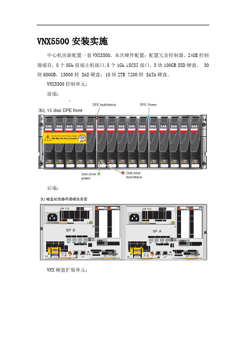
VNX5500安装实施
中心机房新配置一套VNX5500,本次硬件配置:配置冗余控制器,24GB控制器缓存, 8个8Gb前端主机接口,8个1Gb iSCSI接口, 5块100GB SSD硬盘, 30块600GB,15000转 SAS硬盘;10块2TB 7200转 SATA硬盘。
VNX5500控制单元:
前端:
后端:
VNX硬盘扩展单元:
上架安装示意图:
电源连接示意图:
电源监控连接示意图:
扩展柜电源连接示意图:
电缆线连接图:
安装前面板:
创建 RAID Group
打开存储设备,选择“Storage Pools”,打开,然后右键选择“RAID Groups”,根据如下表进行创建。
再点“Create RAID Groups”,
指定Stroage Pool ID,在“Disks”标签框里选择“Manual”单选按钮,点击“Select”,
右边的已经选中的磁盘全部移到左边,然后从“Select From:”下拉列表中选择要添加的磁盘所处的磁盘柜,
创建 Hotspare
创建 LUN。
Series 5500 高级和备用安装说明书

Series 5500Advanced and alternateNote: These installation instructions are a supplement to the approved final shop drawings and are to be used in conjunction with those drawings. TABLE OF CONTENTS S-5500 ADVANCED INSTALLATION INSTUCTIONS SECTIONPAGEI. General Notes and Guidelines………………………………………...……... 3-4 II. Frame Unit Assembly & Frame Sealing Shear Block……………………………………...…………………………………. 5-6 III. Alternate Anchorage Methods Sleeve Anchors………………………………………………………………….. 7-10 Mull Anchors …………………………………………………………………… 11-17 IV . Punched Opening & Ribbon WindowsFrame Unit Assemble & Frame Sealing..………….……………………18-20 Alternate Anchorage Method……………………………………………… 21-23V . Vertical Splice Joints……………………………………………………………. 24-33 VI. Expansion Mullions…………………………………...………………………... 34-37VII. Glazing At Spandrel Areas of Inside Glazed Frames ……………….. 37-40 VIII. Glazing Adaptors Captured Glazing………………………………………………………………….. 41 Silicone Structural Glazed …………………………………………………. 43-46 Note: This document is to be used in conjunction with the standard installation instructions.Minimizing CondensationNote: Please reference EFCO's "Understanding Condensation" brochure which can be obtained through your EFCOrepresentative.Condensation will form on any surface when unfavorable conditions (interior temperature and relative humidity andexterior temperature) are present. When the formation of excessive condensation is a concern, it is highly recommended that adesign professional is utilized to perform an analysis of the shop drawings to recommend the best possible installation methods.Please contact your EFCO representative for information on EFCO's Thermal Analysis Services.Many current installation practices lead to an increase in the possibility of the formation of condensation. Though not allinclusive, the list of examples below illustrates conditions under which condensation is likely to occur:1. Bridging system thermal break with non-thermally broken metal flashing or lintels that are exposed to theexterior2. System exposure to cold air cavities3. Interior relative humidity levels not maintained at recommended levels, see EFCO’s “UnderstandingCondensation” brochure4. Inadequate separation between system and surrounding condition at perimeter5. Product combinations during the shop drawing stage that result in bridging thermal breaks of one or all products involvedSection I: General Notes and GuidelinesI. HANDLING / STORING / PROTECTING ALUMINUM - The following precautions arerecommended to assure early acceptance of your products and workmanship.A. HANDLE CAREFULLY - Store with adequate separation between components sothe material will not rub together. Store the material off the ground. Protect ma-terials against weather elements and other construction trades.B.KEEP MATERIAL AWAY FROM WATER, MUD, AND SPRAY - Prevent cement,plaster, and other materials from contacting with and damaging the finish. Do notallow moisture to be trapped between the finished surface and the wrapping mate-rial.C. PROTECT MATERIALS AFTER ERECTION - Wrap or erect screens of plasticsheeting over material. Cement, plaster, terrazzo, and other alkaline materials arevery harmful to the finish and are to be removed with soap and water before hard-ening. Under no circumstances should these materials be allowed to dry or perma-nent staining will occur.II. GENERAL GUIDELINES - The following practices are recommended for all installations:A. REVIEW APPROVED SHOP DRAWINGS – Become thoroughly familiar with theproject. Shop drawings govern when conflicting information exists in these installa-tion instructions.B. INSTALL ALL FRAMING MATERIAL PLUMB, LEVEL, AND TRUE – Properalignment and relationships to benchmarks and column centerlines, as establishedby the architectural drawings and the general contractor, must be maintained.C. The sequence of erection should be coordinated with the project superintendent toprevent delays and minimize the risk of material damage. Note: If preset an-chors are required, coordinate and supervise anchor placement with thegeneral contractor.D. Verify that all job site conditions and accompanying substrates receiving the instal-lation are in accordance with the contract documents. If deviations occur, notifica-tion must be given IN WRITING to the general contractor and differences re-solved before proceeding further with the installation in the questionable area.E. Prevent all aluminum from coming in direct contact with masonry or dissimilar ma-terials by means of an appropriate primer.SECTION I: GENERAL NOTES and GUIDELINESF. Follow EFCO framing installation and glazing instructions.G. Verify contents of all material shipments received upon their arrival. Verify quantityand correct finishes. NOTIFY EFCO IMMEDIATELY OF ANY DISCREPANCIESOR DAMAGE THAT MAY HAVE OCCURRED.H. Throughout these instructions the term “SEALANT” will appear. For the purposes ofthese instructions, sealant is to be defined as the following:SEALANT - A weather resistant, gunnable liquid filler which when cured provides aresilient, flexible (± 50% movement capability) air and water seal between similarand dissimilar materials.All sealant must meet ASTM C 920, CLASS 50.BUTYL SEALANT- A non-skinning, non-hardening material (NAAMM Refer-ence Standard 5C-1).NOTE: All sealant must be compatible with all surfaces on which adhesion is re-quired, including other sealant surfaces. All frame surfaces should be clean,dry, dust, and frost free. If a primer is required, it must be applied to cleansurfaces. All perimeter substrates shall be clean and properly treated to re-ceive sealant.This system is designed and has been tested to utilize butyl or silicone seal-ants at all internal joineries, i.e., joint plugs, gasket intersections, etc.Regardless of the sealant used, the customer should contact the sealantmanufacturer to determine compatibility and adhesion. Follow sealant manu-facturer's proper application procedures and quality assurance programs forweather sealing.Maintain caulk joints as shown in the approved shop drawings. Unlessspecified otherwise, most sealant manufacturers recommend a 3/8” mini-mum perimeter caulk joint. A 3/4” minimum joint is recommended at thehead condition to accommodate thermal expansion and contraction.Anchoring surfaces of perimeter construction must be level and plumb withinthe adjustable limits of the head, jamb, and sill framing.Note: It is up to the responsible engineer to determine the structural adequacy and type of anchorage method to be used for a given substrate, applied loads, and building movements. The S-5500 has differentanchorage options available to meet these conditions.Section III: Alternate Anchorage Method (Heavy-Duty Anchor Connections)STEP #1 ASSEMBLE OUTSIDE GLAZED FRAME MEMBERSThis method of anchorage is available for conditions where the standard head and sill anchors or alternate head anchors are not adequate for the given design criteria. Please consult with the structural engineer responsible for the shop drawings for your project.A. Assemble verticals and intermediate horizontals following the frame assembly and sealinginstructions in Section II. Shear blocks should be installed after the frames are set andanchored to avoid interference with the anchor bolts.B. Insert ‘F’ anchors into each end of the jamb mullion and ‘M’ anchors into each end of theintermediate vertical.STEP #3 INSTALL FRAME COMPONENTSA. From pages 12, 13, and 14, repeat steps 1 and 2. Set each successive frame into theopening, snapping the verticals and fillers at each frame-until all frames are installed upto the last frame at the opposite jamb.B. Check frequently to ensure the installed framing is in the proper position with regard toestablished benchmarks.NOTE: On long runs, check overall frame dimensions at every fifth opening to avoiddimensional build-up. The commercial cut length tolerance is +/- 1/16”. It is criticalIMPORTANT NOTE:It is critical to allow at least a ¾” space between the perimeter of the jamb mullion andHEADSTEP #1 ASSEMBLE OUTSIDE GLAZED FRAME MEMBERSA. Seal the ends of the vertical mullions at the exterior and snap-in the PVC fillers. (Section II ofthe Standard Installation Instructions).B. The base section of the two-part anchor must be slid into the heads and sills prior toassembling the frames. The remaining part of the anchor can be applied in the field.C. Sealant must be applied to the ends of each horizontal member before assembly. (Seeenlargement Section II of the Standard Installation Instructions.)D. Assemble the frames per the approved shop drawings.STEP #1 SIDE STACK PRE-ASSEMBLED FRAMESFrames can be partially assembled off-site and moved to the jobsite. Then, groups of frames may be snapped together, allowing them to be set into the opening at one time. The size of the group of frames to be installed is limited by the field’s handling capacity due to the weight and size of the assemblies.STEP #2 PREPARE TO SET FRAMESA. Slide the anchor plates into the base anchors that were installed during frame assembly.B. Refer to the approved shop drawings to review anchor placement, type, and conditions.Section V: PUNCHED OPENING & RIBBON WINDOWS(Alternate Anchorage Method)STEP #3 SET GROUPS OF FRAMESA. Set the assembled groups of frames into the opening.B. Using dead load shims under each vertical mullion, level the frame and set it to theappropriate elevation as indicated in the approved shop drawings.C. Use shims between the anchor plate and the condition to set the frame the properdistance to the face of the building. After the frames are plumb and the frames have been properly installed relative to established benchmarks, match drill through the holes in the anchor plates into the surrounding substrate, and apply the appropriate anchor bolts. Anchor bolt size, type, quantity, and location vary. Refer to the approved shop drawings for more information. Anchor bolts should be installed per the recommendations of the bolt manufacturer.Section V: PUNCHED OPENING & RIBBON WINDOWS(Alternate Anchorage Method)Section V: PUNCHED OPENING & RIBBON WINDOWS(Alternate Anchorage Method)Section V: Vertical Splice JointsSTEP #1 LOCATE SPLICE JOINTSA. Splice joints should occur at spandrel areas (if possible). Refer to the approved shopdrawings for actual locations.B. Depending on job requirements, the mullion splice may be shop or field assembled inthe top of the lower mullion. The cover splice is attached to the bottom of the upper mullion. Where head clearance is insufficient to allow the top mullion to be lifted over the splice sleeves, retractable splices should be used. The splices are to be taped into the bottom of the top mullion and dropped down to the stop screw in the mullion below.C. GENERAL NOTE: The following pages depict a splice joint of 1/2”. This will allow plusor minus 1/4” of movement for each splice location. Thermal expansion and live deflection requirements should be considered when determining the location andquantities of splice joints. If the total amount of movement cannot be accommodated locating splices at every other floor or alternatively at each floor, expansionhorizontals or some alternative method should be used. Contact EFCO for further evaluation.D. Refer to this section for pressure cover splice locations, mullion splice locations, andsealing instructions.E. Once a final check of expansion joint placement and mullion position is made, the finalmatch drilling of mullion through anchor holes may be completed.Section V: Vertical Splice JointsSection V: Vertical Splice JointsSection V: Vertical Splice JointsSTEP #3 CRITICAL MULLION SEAL AT SPLICEA. Insert the 1/4” x 1” x 5” long foam caulk joint backer as shown below leaving 1” ofthe backer extending above the top of the mullion.B. Apply sealant between the thermal struts, starting where the notch in the mullionbegins at the exterior cover, sealing the space to the top of the mullion as shown.C. Tool the sealant flush with the face of the notch of the thermal struts.Section V: Vertical Splice JointsSTEP #4 ATTACH MULLION COVER SPLICE SLEEVESA. Apply bond breaker tape to the mullion cover splice sleeve.B. For standard installation, attach the mullion cover splice sleeve to the bottom of theupper mullion with splice sleeve attachment screws. Cap seal the fastener heads.STEP #5 ALIGN AND STACK ASSEMBLED FRAMESA. Align the pre-assembled frames and stack together at the splice joints.B. Ensure the 1/4” x 1” x 5” long foam caulk joint backer is inserted into the gapbetween the thermal struts in the upper mullion as noted below.C. Position the mullions to the appropriate elevation with regard to establishedbenchmarks, and shim or fix the mullions at their respective dead load anchorpoints.D. Snap-in both of the adjacent frames before sealing the mullion splice joints.E. Clean the splice sealant-contact areas per sealant manufacturer’srecommendations.F. Apply backer rod between the mullions, adapters, and splice to back-up the joint,seal the joint and tool as shown on page 30.STEP #6 SEAL MULLION SPLICEA. Install backer rod to back-up the sealant at the mullion joints as shown on page 24.B. Apply sealant into the mullion splice joint and tool the joint. Do not obstruct theglazing reglets.C. Apply sealant into the pressure cover splice joint and tool the joint. Do not obstructthe glazing reglets.D. Apply sealant around the 1/4” x 1” x 5” long foam caulk joint backer. Tool the jointand blend the sealant into the mullion splice joint and over the thermal struts. Aminimum of 1/4” sealant surface contact with bonding surfaces is required.E. Apply sealant into the joint between the notched thermal struts and the back of thenotched pressure cover and tool the joint smooth (see page 31.)STEP #7 INSTALL AND SEAL ADAPTERSA. Seal gasket races continuously and snap-in adapters, if required.B. Snap-in adapters, carefully using a small pry bar, if required.C. Install backer rod to back-up sealant at the glazing adapters.D. Apply sealant and tool into joints. Do not obstruct the glazing reglets.STEP #8 INSTALL INTERIOR GASKETS, GLAZING, AND EXTERIOR GASKETSA. Install the interior gaskets allowing them to span the mullion splice joint.B. Set the glazing into the opening as previously instructed.C. Apply the exterior vertical drive-in wedge gaskets into the vertical mullions asshown in Section VI of the Standard Installation Instructions.D. Apply the horizontal pressure covers and horizontal exterior drive-in wedgegaskets at the top and bottom of the lite as shown in the Standard InstallationInstructions.STEP #1 PREPARE EXPANSION MULLIONSExpansion mullions are required for elevations wider than 20’-0”. The maximum spacing between expansion mullions is 20’-0”. Refer to the approved shop drawings for specific locations and more information.A. Thread the finger gaskets into the reglets of the male half of the expansionmullion for the full length of the mullion. Refer to the approved shop drawings forpart numbers.B. Crimp the reglet at the finger gaskets about ½” from each end with a chisel orsimilar tool to lock the gasket in place.STEP #1 (Continued) PREPARE EXPANSION MULLIONSWhen vertical D.L.O.s exceed 48”, mullion clips may be required at the center of the lite. Contact EFCO or refer to the approved shop drawings for more information.A. Slide the mullion clips into the grooves of the mullion as shown below.B. Crimp the legs at each end of the mullion clip with a punch or similar tool to lock it inplace. Refer to the approved shop drawings for more information.STEP #2 STACK EXPANSION MULLIONSA. Apply a continuous bead of sealant to the male mullion half as noted below.B. After the frames are assembled as instructed in Section II, install the frames using theanchor methods required. Stack the expansion mullions together using ‘C’ clamps to press each half of the mullion together. Use shims as shown below to prevent from closing the expansion mullion. Remove the shims after the anchors are set.C. Tool the sealant joint in the space between the expansion mullions as shown below.This seal will marry with the joint plug seals when the joint plugs are applied.STEP #3 GLAZE EXPANSION MULLIONSA. Glaze the curtain wall as instructed in Sections IV, V, and VI of the StandardInstallation Instructions.IMPORTANT NOTE: The horizontal and horizontal pressure cover must be notched, or cut 1/8” short on the male mullion side of the glazing pocket, as shown below to allow for horizontal expansion and contraction of the curtain wall.Note: S-5500 curtain wall must be outside glazed at the floor lines, some column locations, shearwalls and parapet areas, or any other area that would not allow the glazing infill to be inside set.Refer to the approved shop drawings for locations and exact configuration of the spandrel areas. The following is a guide for a typical floor line spandrel installation.GLAZING SPANDREL AREAS AT FLOOR LINESA. Vision lites will consist of inside glazed horizontals at the head of the lite as shown in“FIGURE A” below.B. The top of the spandrel lite and any intermediate horizontals within the spandrel areas willconsist of an outside glazed horizontal with a roll-on pressure cover as shown in “FIGURE B”below.C. The bottom of the spandrel lite above the vision area will consist of an inside/outside-glazedhorizontal with a roll-on pressure cover and removable interior bead as shown in “FIGUREC” below. This will allow the spandrel lite to be outside set and the vision lite to be insideSTEP #2 INSTALL SETTING BLOCKS AND PRESET GASKETS INTO MULLIONSA. Apply the setting blocks at the bottom of the spandrel lites per the approved shopdrawings.B. Install the preset glazing gaskets per “Glazing Preparation” in Section IV of theStandard Installation Instructions, except the gaskets will be set on the interior sideof the glazing pocket as shown below.Section VIII: Captured Glazing Adaptor InstallationSTEP #1 INSTALL GLAZING ADAPTERSA. Prior to installing the glazing adapters, seal the full length of the gasket racewaywith sealant.B. Snap the glazing adapters in place into the sealant starting with the verticals.Allow at least 1/8” clearance from the bottom of the glazing adapters to the top ofthe joint plugs to allow for weepage.C. Apply sealant to the ends of the horizontal adapters prior to setting them intoposition. Snap the horizontal adapters in place between the vertical adapters. Sealthe face of the adaptor intersections with sealant. Tool all sealant joints andremove all excess sealant.STEP #1 INSTALL GLAZING ADAPTERS (CONTINUED)STEP #1 INSTALL GLAZING ADAPTERS (CONTINUED)STEP #1 INSTALL GLAZING ADAPTERS (CONTINUED)STEP #1 INSTALL GLAZING ADAPTERS (CONTINUED)。
VNX安装文档
图标下方如果出现T字样,表示需要等候一会即可正常。常出现在进行了RAID创建的LUN上和电池充电中。
红色×
表示管理的PC终端此时网络不能联结存储,检查网络即可。
U字样
表示不可管理,比如将存储设备上的网线拔掉会导致主控卡SPA或SPB出现不可管理。
主机出现U字样,表示TCP/IP网络与存储联结有问题,如果此主机能够PING通存储的IP地址,那么就是AGENT软件与存储通讯有问题。但是,主机出现U字样,与存储的数据访问没有关系,绝对不会影响存储的访问。
2、还有一种是收集存储的实时日志文件,选择Unisphere移至Dashbored展开后选择SP Event Logs。
随后选择Show SP A Event Log就可以查看并保存控制器的实时日志,
END
1.关闭机柜最底部的两个电池开关并等待约3分钟直到存储写缓存中的数据完全写入到硬盘上后,可看到电池的信号灯完全熄灭,且应看到因电池停止供电,SPE或DPE机箱及DAE-OS磁盘机箱的电源灯熄灭。
2.由下至上,关闭所有DAE磁盘机箱的开关(机柜内部的PDU)
3.关闭机柜后面两侧机柜总开关
4.关机完成.
如果一定要测试,建议由我们的工程师用命令行来执行磁盘离线测试
PC终端安装了JAVA后台后就可以直接使用上述地址进行管理。
红色F字样
如果出现红色F字样,表示出现硬件故障,但如果重启存储,会导致SPS电池进行充放电操作来确认电池工作正常,同时电池后部的指示灯会呈持续闪动的绿色。在BUS 0 ENCLOSURE里的电池(SPS)也会出现红色F字样,过半小时后电压升高至标准后F变成蓝色T字样后,过一会会消失,这是正常现象。
2.从机柜顶部开始,由上至下打开所有DAE磁盘机箱的电源。
EMC-VNX5500磁盘阵列开关机操作指南

上海小糸车灯有限公司存储项目之阿布丰王创作VNX5500磁盘阵列开关机操纵说明上海软盛信息技术有限公司2012年9月1、设备开机通电1.1开机前的准备1、检查磁盘阵列电源线缆及各部分连接的线缆是否都已经接好。
2、检查供电电源的来源是否是UPS设备输出,其供电电压电流是否稳定3、磁盘阵列在加电前,为确保磁盘柜散热和工作正常,请确认所有磁盘柜的每个槽位都已经插上硬盘和挡风板。
4、开机前需确保至少要有一个正常工作的SP,每个DAE都至少要一块正常工作的LCC。
1.2开机的基本顺序1、打开光纤交换机2、打开磁盘阵列电源3、打开服务器电源1.3磁盘阵列开机的顺序1、打开扩展柜DAE电源2、打开主控制柜DPE、SPS电源3、打开数据移动器(俗称NAS头)DataMover电源备注:对于本次项目,由于配备了EMC机柜及电源,DPE、DAE、DM等设备模块直接打开机柜PDU电源即完成加电。
4、打开ControlStation控制器电源(控制器开机电源见3.3各部分说明)1.4具体操纵本次项目VNX5500 for file 和 VNX5500 for unified 可以配备两个刀片(DataMover)以及一个控制站(Control Station)。
操纵步调:1. 验证每个机柜接线板的主开关/断路器是否处于打开状态。
如果要接通包含其他组件的机柜中的VNX5500的电源,请勿关闭机柜的断路器。
确保SPS开关处于关闭位置。
2. 确保 SP A的电源线拔出到SPS中,而且电源线固定扣也扣入到位。
3. 确保 SP B的电源线拔出到SPS A之外的另一电路上最近的配电装置(PDU)中,而且电源线固定扣也扣入到位。
在具有两个SPS的系统中,请将 SPB拔出到 SPS B中。
4. 验证连接每个 SPS 的电源线是否连接到适当的机柜接线板而且固定扣也扣入到位。
5. 验证全部 DAE的电源线是否已拔出到机柜的接线板中。
6. 打开SPS电源开关。
- 1、下载文档前请自行甄别文档内容的完整性,平台不提供额外的编辑、内容补充、找答案等附加服务。
- 2、"仅部分预览"的文档,不可在线预览部分如存在完整性等问题,可反馈申请退款(可完整预览的文档不适用该条件!)。
- 3、如文档侵犯您的权益,请联系客服反馈,我们会尽快为您处理(人工客服工作时间:9:00-18:30)。
EMC 确信本出版物自发布之日起内容准确无误。
如有更改,恕不另行通知。
本出版物的内容按“原样”提供。
EMC CORPORATION 对本出版物的内容不提供任何形式的陈述或担保,明确拒绝对有特定目的的适销性或适用性进行默示担保。
使用、复制或发行本出版物所描述的任何 EMC 软件都要有相应的软件许可证。
有关产品系列的最新法规文档,请访问 EMC 在线支持站点上的“技术文档和咨询”部分。
有关 EMC 产品名称的最新清单,请参见 上的 EMC Corporation 商标。
此处使用的所有其他商标均为其各自所有者的资产。
客户意见和建议
您的意见和建议可以帮助我们继续提高用户出版物的准确性、组织结构和整体质量。
请将对本文档的评价发送到:
techpubcomments@
版权所有 © 2011, EMC Corporation。
保留所有权利。
2011 年 3 月出版。