BS-120装机指南(第三版)
VISTA120安装手册简易(新)

VISTA-120防盗控制/通讯主机128防区 8个子系统 时间管理功能 32个继电器输出 150个使用者密码 224起事件记录安装编程手册ADEMCO 安定宝目录第一章安装说明 (2)一.VISTA-120主机系统结构。
(2)二.VISTA-120主机性能说明。
(6)三、安装操作说明: (7)1、事件登记 (7)第二章编程说明 (16)一.防区类型 (16)二.布防方式与防区类型之关系: (17)三.编程概述: (17)四.编程模式编程说明: (19)五.操作编程: (33)第三章系统操作与测试 (36)一。
键盘操作 (36)第四章安装编程实例 (39)一.基础安装编程例子: (39)二.扩充功能安装编程例子: (41)第五章排错指南 (42)第一章安装说明一.VISTA-120主机系统结构。
VISTA-120是一种大型自动化防盗控制/通讯主机,它包含的功能很多,上图中除去虚线框部分即为基本安装单元,虚线框部分是选择的扩充功能部分,分别是:A.防区扩充部分:有总线与无线扩充两种。
B.继电器输出部分。
C.多个子系统操作部分。
1。
固定:VISTA-120主机附带一个安装箱,主机板、电源、后备电池等均可安装在内。
安装电源连接线、警号线、电话线等应注意隐蔽以防破坏。
安装主机板时应注意应用附配的塑料垫子架在主机箱的固定孔上,以免短路。
主机箱固定于隐蔽处,如吊天花后的天花板上或柜子里;键盘则安装在较容易操作的地方,如门后;警号则安装于指向保护区的地方;各种扩充器则安装在靠近控制设备的附近,如4208总线扩充器安装在探头附近,4204继电器模组安装在控制的电器附近,4281/5881无线接收机安装在无线探头附近,尽量缩短距离以达到较好的接收效果。
主机板上端子30是接地端,为防止雷击、电击破坏主机或伤人,必须把该端子接地,可以接于水管上。
常闭输出探头2。
防区与探头VISTA-120主机可以容纳多达128个不同的防区,即表示系统可以接入128个可一一区分出来的探头,同时,每个防区按照接入不同类型的探头,并通过编程设定为某类型的防区,以使操作方便与报警更加可靠。
FactoryTalk View Site Edition 安装指南说明书

注意:标识可能导致人员伤亡、财物损害或经济损失的做法或环境的相关信息。注意事可帮助您识别危险,避开 危险,以及意识到后果。
重要 标识对成功应用和了解产品至关重要的信息。 还会在设备上或内部使用标签来提供具体预防措施。
章节 2 系统要求
我可以在一台服务器上安装和运行什么? ................................................................................................15 查看硬件要求 ..................................................................................................................................................15 查看操作系统要求 .......................................................................................................................................... 16
章节 3 预安装配置
禁用 Windows 自动更新..............................................................................................................................19 配置 NIC 和交换机端口...............................................................................................................................19 禁用或卸载第三方防火墙 ............................................................................................................................20 移除增强的安全配置 ....................................................................................................................................20
BS EN 120 中文
BS EN 120:1992穿孔萃取法测定人造板甲醛释放量1.测试目的与适用范围:本标准用于测试非层压板及非涂层人造板甲醛释放量。
2. 测试原理:将溶剂甲苯与试件共热,通过液-固萃取使甲醛从板材中溶解出来,然后将溶有甲醛的甲苯通过穿孔器与水进行液-液萃取,把甲醛溶于水中。
用乙酰丙酮分光光度法测定试样溶液的吸光度,由预先绘制的标准曲线求得甲醛释放量。
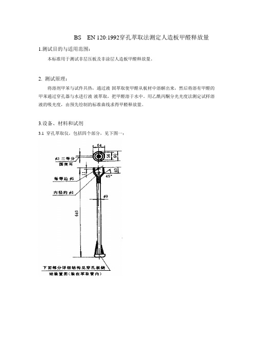
3.设备、材料和试剂3.1 穿孔萃取仪,包括四个部分,见下图一:萃取管穿孔器中穿孔板烧结装置穿孔萃取装置图一测定甲醛释放量的穿孔萃取仪部件图3.1.1 标准磨口圆底烧瓶,1000 mL,用以加热试件与溶剂进行液一固萃取;3.1.2 萃取管,具有边管(包以石棉绳)与小虹吸管,中间放置穿孔器进行液一液穿孔萃取;3.1.3 冷凝管,通过一个大小接头与萃取管联结,可促成甲醛一甲苯气体冷却液化与回流;3.1.4 液封装置,防止甲醛气体逸出的虹吸装置,包括90°弯头,小直管防虹吸球与三角烧瓶3.2 恒温加热套,宜于加热1000 mL 圆底烧瓶,功率300 W,可调温度范围50~20 0℃。
3.3 分析天平3.4 鼓风干燥箱,能保持(103 ± 2)℃3.5 恒温水浴锅3.6 可见分光光度计。
3.7 玻璃器皿滴定管:50 mL;碘量瓶:500 mL;烧杯:100 mL,250 mL,500 mL,1000 mL;容量瓶:1000 mL,100 mL,2000 mL;棕色容量瓶:1000 mL;移液管:2.0 mL,5 mL,25 mL,50 mL,100 mL;50 mL 具塞比色管;玻璃研钵,直径10 ~12 cm。
3.8 小口塑料瓶,500 mL 与1000 mL。
3.9 试剂甲苯(C7H8),分析纯碘化钾( KI ),分析纯;重铬酸钾(K2Cr2O7),优级纯;硫代硫酸钠(Na2S2O3·5H2O),分析纯;碘化汞(Hgl2),分析纯;无水碳酸钠(Na2CO3),分析纯;硫酸(H2SO4),ρ=1.84g/mL,分析纯;盐酸(HCl),ρ=1.19g/mL,分析纯;氢氧化钠(NaOH),分析纯;碘(I2),分析纯;可溶性淀粉,分析纯;乙酰丙酮(CH3COCH3COCH3) ,优级纯;乙酸铵(CH3COONH4),优级纯;甲醛溶液(CH20),浓度35%-40%。
BS120操作

BS-220生化分析仪简易操作指南一﹑开机前检查1.检查去离子水是否充足,废液及废料桶是否满,如果已满,进行清理。
2.检查采样针,搅拌棒的位置是否置于清洗池内剧中,且无变形。
3.将试剂盘放入试剂仓内,注意位置要到位;检查试剂39号位有足够CD80,40号位有足够的蒸馏水。
4.检查电源线及串口电缆线连接良好,电压稳定在AC 220V±10%。
二﹑开机打开生化分析仪主电源开关→分析部电源开关→显示器→电脑电源→打印机电源。
三﹑启动控制软件双击BS-220图标→输入用户名(Admin),密码(Admin)→仪器自检完毕后,按照对话框提示,将第一反应杯取出,点确定→仪器执行完光源本底测试后,按照对话框提示,点确定键执行更换反应杯操作,将反应杯放入第一杯联位,点击换杯→换杯完毕后点反应杯扫描→扫描完毕点结束→按照对话框提示,点击确定(强化清洗)或下一步(水清洗)执行清洗,开机完成。
四﹑样本申请1.点击样本申请,选择样本盘,样本位,是否急诊,点击需申请的项目,点确定后完成申请。
2.将离心好的血清标本放入指定的试管位,点开始测试。
3.编辑病人信息,可在结果查看内点击病人信息输入。
4.测试完成后,点结果查看,选择需打印的病人,点打印。
五﹑定标设置及定标1.点定标,进入定标液设置,点添加定标液,输入定标液名称(如H2O水),批号,有效期,位置(如3-1不可重复)等信息,输入浓度,(注意:水在定标中是必不可少的,水对于所有项目的浓度应设为‘0’)。
添加水后,再用同样的方法添加各项目的定标液,对应项目定标液的浓度在试剂说明书上,或使用复合定标液(1支能定多个项目,有特定的浓度表)。
2.选择参数,点击定标规则,选中项目名称,在定标规则中选择两点线性,定标次数选择3次,将H2O(水)和对应项目定标液打上√。
3.选择定标→定标申请→选择项目→确定→开始测试。
请选择配套试剂﹑定标液﹑质控液。
3HAC035960-zh-cn
产品规格 IRB 120
Trace back information: Workspace R13-2 version a3 Checked in 2013-10-15 Skribenta version 4.0.378
产品规格 IRB 120-3/0.6 IRB 120T-3/0.6
用户
它面向: • 产品经理和产品相关人员 • 销售和市场营销人员 • 订购和客服人员
参考信息
参考文档
文档编号
Product specification - Controller software IRC5
3HAC022349-001
Product specification - Controller IRC5 with FlexPendant 3HAC041344-001
1.4 载荷图 ............................................................................................................. 19 1.4.1 载荷图简介 ............................................................................................. 19 1.4.2 载荷图 ................................................................................................... 20 1.4.3 轴 5(中心线向下)全程或受限运动的最大载荷和转动惯量 ................................ 22
H-300B-20-47612 HYPERVISOR VI 维修手册(中文)-15.0

版本信息
本维修手册的版本号随时可能因软件或技术规格的变更而升级,恕不另行通知。本维 修手册的版本信息如下: 版本号: 发行时间: 15.0 2015 年 04 月
© 2007-2015 深圳迈瑞生物医疗电子股份有限公司,版权所有。保留所有权利。
I
ห้องสมุดไป่ตู้ 声
明
迈瑞公司保留不事先通知而修改本维修手册内容的权利。 迈瑞公司保留不事先通知而变更技术的权利。 迈瑞公司保留不事先通知而对产品规格进行修改的权利。 迈瑞公司对于本资料不作任何形式的担保,包括(但不限于)为某种特定目的对其提 出的暗含的适销性和适合性的保证责任。 迈瑞公司仅仅在下列情况下才认为应对产品的安全性、可靠性和性能负责,即: 装配操作、扩充、重调、改进和修理均由迈瑞公司认可的人员进行; 有关的电气设备符合国家标准; 产品按照《使用说明书》进行使用。
HYPERVISOR VI 中心监护系统 Central Monitoring System
维修手册 Service Manual
知识产权
本产品及其维修手册的知识产权属于深圳迈瑞生物医疗电子股份有限公司(以下简称 迈瑞公司) ,包括但不限于专利权、商标权、著作权等。 迈瑞公司有权将本维修手册作为保密资料处理。未经迈瑞公司书面许可,任何个人或 组织不得以任何手段披露此维修手册的全部或部分信息,也不得允许他人或组织以任何手 段获取本维修手册的全部或部分信息。未经迈瑞公司书面许可,任何个人或组织不得对本 维修手册的全部或部分内容有(但不限于)发表、修改、复制、发行、出租、改编以及翻 译成其它语言之行为。
售后服务单位
名称: 地址: 邮编: 电话: 传真: 深圳迈瑞生物医疗电子股份有限公司用户服务部 深圳市南山区高新技术产业园区科技南十二路迈瑞大厦 518057 +86 755 81888998 +86 755 26582680
ADEMCO VISTA VISTA-120 120 分子系统报警控制通信主机 安装配置指南

第三章:
第四章:
第五章:
第六章:
第七章:
ii
总线回路的局限性 ...........................................................................................20 总线回路监测 ..................................................................................................21 维持信号支持 ..................................................................................................22 总线回路检查步骤 ...........................................................................................22 兼容的总线设备...............................................................................................23 第八章: 无线防区扩充 ...................................................................................................24 无线系统操作/监测 ..........................................................................................24 无线系统安装指南 ...
指南引擎Ultra3000驱动系统目录号2098-DSD-005、2098-DSD-010等说明书

Design GuideUltra3000 Drive SystemsCatalog Numbers2098-DSD-005, 2098-DSD-010, 2098-DSD-020, 2098-DSD-005X, 2098-DSD-010X, 2098-DSD-020X,2098-DSD-005-SE, 2098-DSD-010-SE, 2098-DSD-020-SE, 2098-DSD-005-DN, 2098-DSD-010-DN, 2098-DSD-020-DN,2098-DSD-005X-DN, 2098-DSD-010X-DN, 2098-DSD-020X-DN,2098-DSD-030, 2098-DSD-075, 2098-DSD-150, 2098-DSD-030X, 2098-DSD-075X, 2098-DSD-150X,2098-DSD-030-SE, 2098-DSD-075-SE, 2098-DSD-150-SE, 2098-DSD-030-DN, 2098-DSD-075-DN, 2098-DSD-150-DN,2098-DSD-030X-DN, 2098-DSD-075X-DN, 2098-DSD-150X-DN,2098-DSD-HV030, 2098-DSD-HV050, 2098-DSD-HV100, 2098-DSD-HV150, 2098-DSD-HV220, 2098-DSD-HV030X, 2098-DSD-HV050X, 2098-DSD-HV100X, 2098-DSD-HV150X, 2098-DSD-HV220X,2098-DSD-HV030-SE, 2098-DSD-HV050-SE, 2098-DSD-HV100-SE, 2098-DSD-HV150-SE, 2098-DSD-HV220-SE,2098-DSD-HV030-DN, 2098-DSD-HV050-DN, 2098-DSD-HV100-DN, 2098-DSD-HV150-DN, 2098-DSD-HV220-DN,2098-DSD-HV030X-DN, 2098-DSD-HV050X-DN, 2098-DSD-HV100X-DN, 2098-DSD-HV150X-DN, 2098-DSD-HV220X-DNTopic Page Topic (continued)Page Introduction2Linear Motion System Combinations Determine What You Need 3MP-Series Integrated Linear Stages 46Ultra3000 System Examples4MP-Series Electric Cylinders 532090-Series Motor/Actuator Cables Overview 7MP-Series Heavy Duty Electric Cylinders 56Rotary Motion System Combinations LDC-Series Linear Motors 62MP-Series Low Inertia Motors 9LDL-Series Linear Motors 72MP-Series Medium Inertia Motors 23Additional Resources76MP-Series Food Grade Motors 34MP-Series Stainless Steel Motors 39TL-Series (Bulletin TLY) Motors42Ultra3000 Drive SystemsIntroductionThis publication assumes that the drive family for your application is Ultra™ 3000 and that you have already determined your motor catalog number. T o revisit those decisions, refer to the Kinetix® Motion Control Selection Guide, publication GMC-SG001, or Motion Analyzer software.The purpose of this publication is to assist you in identifying the drive system components and accessory items you’ll need for your Ultra3000 drive and motor/actuator combination. Diagrams in this publication illustrate how many of the common drive accessory items are used in a typical system, but refer to the Kinetix Motion Accessories T echnical Data, publication GMC-TD004, for detailed accessory descriptions and specifications.Also provided are drive/motor or drive/actuator system combinations that include the following:•Motor/cable combinations table•Drive and motor/actuator performance specification table•T orque/speed curves with each motor matched to the drive with optimum performancePerformance specification data and curves reflect nominal system performance of a typical system with motor/drive at rated ambient temperature and line voltage. For additional information on ambients, line conditions, and valid combinations not shown in this publication, refer to Motion Analyzer software.IMPORTANT These system combinations do not include all possible motor/drive combinations. Please refer to Motion Analyzer software to verify compatibility. Download is available at /motion/software/analyzer.html.2Rockwell Automation Publication GMC-RM008A-EN-P - September 2011Rockwell Automation Publication GMC-RM008A-EN-P - September 20113Ultra3000 Drive SystemsDetermine What You NeedFor each Ultra3000 drive system, you need to know the drive and motor/actuator catalog numbers to determine the motor power and feedback cable catalog numbers. Interface cables and connector kits are also required. Optional equipment includes Bulletin 2090 AC line filter, shunt resistor, and others. Example diagrams of the required equipment listed on this page are shown on page 4.Ultra3000 Drive ModulesUltra3000 Servo Drive Communication InterfaceRefer to the Kinetix Servo Drives Specifications T echnical Data, publication GMC-TD003, for detailed descriptions and additional specifications for the Ultra3000 drive family.Ultra3000 Drives Cat. No.Input VoltageOutput Power (continuous)Output Current (continuous)Features2098-DSD-005x-xx 200V Class 0.5 kW 1.8 A, rms •Requires an external 12…24V power supply for proper operation of the digital I/O.•Requires an external +5V power supply to maintain logic power when the AC line voltage is removed. (1)(1)Use external 24V I/O power supply to feed drive-mounted breakout boards (catalog numbers 2090-U3CBB-DM12 and 2090-U3CBB-DM44) with 24…5V DC converter.2098-DSD-010x-xx 1.0 kW 3.5 A, rms 2098-DSD-020x-xx 2.0 kW 7.1 A, rms 2098-DSD-030x-xx 3.0 kW 10.6 A, rms Requires an external 12…24V power supply for proper operation of the digital I/O.2098-DSD-075x-xx 7.5 kW 24.7 A, rms 2098-DSD-150x-xx 15 kW 45.9 A, rms 2098-DSD-HV030x-xx 400V Class 3.0 kW 5.0 A, rms 2098-DSD-HV050x-xx 5.0 kW 7.8 A, rms 2098-DSD-HV100x-xx 10 kW 16.3 A, rms 2098-DSD-HV150x-xx 15 kW 24.0 A, rms 2098-DSD-HV220x-xx22 kW33.2 A, rmsDrive Type Drive Cat. mand Interface SERCOS interface drive 2098-DSD-xxx -SE and 2098-DSD-HV xxx -SE Fiber-optic SERCOS module Analog drive2098-DSD-xxx and 2098-DSD-HV xxx Analog command interface Digital drive with DeviceNet interface 2098-DSD-xxx -DN and 2098-DSD-HV xxx -DN DeviceNet communication interfaceIndexing drive2098-DSD-xxx X and 2098-DSD-HV xxx X Standalone controlIndexing DeviceNet interface drives2098-DSD-xxx X-DN and 2098-DSD-HV xxx X-DN4Rockwell Automation Publication GMC-RM008A-EN-P - September 2011Ultra3000 Drive SystemsRequired Drive AccessoriesRefer to the Kinetix Motion Accessories T echnical Data, publication GMC-TD004, for detailed descriptions and specifications of these servo drive accessories.Ultra3000 System ExamplesThese system examples illustrate how the required drive modules and accessories are used in a typical system.Ultra3000 System Example (SERCOS interface)Drive Accessory DescriptionCat. No.24V power supply12…24V DC for control power and motor brakes.1606-XL xxx Drive-mounted breakout boards (required for flying-lead cables)Motor feedback (CN2) connections.2090-UXBB-DM15Serial interface (CN3) connections.2090-UXBB-DM09I/O (CN1) connections. These kits apply to all Ultra3000 drives and (catalog numbers 2098-DSD-005,2098-DSD-010, and 2098-DSD-020) in applications where 5V DC control power (if required) is user-supplied.2090-U3BB-DM12 (1)(1)The 12-pin board is intended for use with SERCOS drives, but may be used in non-SERCOS applications with minimal I/O requirements.2090-U3BB2-DM44 I/O (CN1) connections. These kits apply to only 2098-DSD-005, 2098-DSD-010, and 2098-DSD-020 drives in applications where a 24…5V DC converter for control power is required.2090-U3CBB-DM12 (1)2090-U3CBB-DM44SERCOS fiber-optic cables (required as needed for SERCOS applications)Plastic, in-cabinet duty.2090-SCEP x -x Plastic, on-machine duty.2090-SCNP x -x Plastic, outdoor and conduit duty.2090-SCVP x -x Glass, outdoor and conduit duty.2090-SCVG x -x Serial interface cable(required for non-SERCOS applications)Ultra3000 serial interface to personal computer.2090-UXPC-D09xxMotor power and feedback cablesRefer to the specific drive/motor combination for the motor cables required for your system.Ultra3000 Drive Systems Ultra3000 System Example (analog or indexing)Ultra3000 System Example (DeviceNet interface)Rockwell Automation Publication GMC-RM008A-EN-P - September 201156Rockwell Automation Publication GMC-RM008A-EN-P - September 2011Ultra3000 Drive SystemsOptional Drive AccessoriesUltra3000 Input Power ExampleMotor-end cable connector kits, for use when building your own cables, are also available. Refer to the Kinetix Motion Accessories T echnical Data, publication GMC-TD004, for detailed descriptions and specifications of optional servo drive accessories.Drive AccessoryDescriptionCat. No.Drive to 1756-M02AE module interface cableSingle-axis (CN1) flying-lead drive to Logix module cable.2090-U3CC-D44xx Two-axis (CN1) pre-wired drive to Logix module cable.2090-U3AE-D44xx Drive-mounted breakout board for serial interface(applies to flying-lead cables as an alternative to serial interface cable)9-pin (CN3) breakout board for serial interface.2090-UXBB-DM09Panel-mounted breakout boards(applies to flying-lead cables as an alternative to drive-mounted breakout boards)DIN rail mounted terminal block and cable for 15-pin (CN2) motor feedback connections.2090-UXBK-D15xx DIN rail mounted terminal block and cable for 44-pin (CN1) I/O connections.2090-U3BK-D44xx 2090 AC line filtersAC line conditioning for EMC. Applies to 200V-class drives. 2090-UXLF-xxx AC line conditioning for EMC. Applies to 400V-class drives.2090-UXLF-HV xxx 2090 shunt modulesApplies to 2098-DSD-HV030, 2098-DSD-HV050, and 2098-DSD-HV100 drives. (1)(1)Refer to Rockwell Automation Encompass™ partners for 2098-DSD-HV150 and 2098-DSD-HV220 passive shunt solutions.2090-SR xxx-xx Applies to 2098-DSD-075 and 2098-DSD-150 drives.2090-UCSR-P900Applies to 2098-DSD-030 drives.9101-1183Applies to 2098-DSD-005, 2098-DSD-010, and 2098-DSD-020 drives.2090-UCSR-A300Resistive brake module (RBM)Physically and electrically separate the drive power output from its corresponding motor.2090-XB xxx-xx RBM interface cables Motor power, RBM to drive.2090-UXNRB-10F1P32090-UXNRB-8F1P42090-UXNRB-6F1P5External auxiliary encoderAllen-Bradley® sine/cosine and incremental external encoders.Bulletin 842A, 844D, 845H, and 845TLine Disconnect Device Magnetic ContactorInput Fusing xxUltra3000 Drive Systems2090-Series Motor/Actuator Cables OverviewFeedback Cable Descriptions (standard, non-flex)(1)Threaded DIN connector (motor end) and bayonet connector for 2090-XXNFMP-S xx cable.Feedback Cable Descriptions (continuous-flex)(1)SpeedTec DIN connector (motor end) and male connector for extending SpeedTec or threaded DIN cable.IMPORTANT Feedback cables with the CE designation, for example 2090-CFBM7DF-CEAA xx, are intended for high-resolution encoder or resolver applications and have fewer conductors than feedback cables with the CD designation, for example2090-CFBM7DF-CDAF xx, which are intended for high-resolution or incremental encoder applications.Rockwell Automation Publication GMC-RM008A-EN-P - September 20117Ultra3000 Drive SystemsPower/Brake Cable Descriptions (standard, non-flex)(1)Threaded DIN connector (motor end) and bayonet connector for 2090-XXNFMP-S xx cable.Power/Brake Cable Descriptions (continuous-flex)8Rockwell Automation Publication GMC-RM008A-EN-P - September 2011Rockwell Automation Publication GMC-RM008A-EN-P - September 20119Ultra3000 Drive SystemsUltra3000 (200V class) Drives with MP-Series Low Inertia MotorsThis section provides system combination information for the Ultra3000 (200V class) drives when matched withMP-Series™ low-inertia motors. Included are motor power/brake and feedback cable catalog numbers, system performance specifications, and the optimum torque/speed curves.Bulletin MPL Motor Cable CombinationsFor cable configuration illustrations and feature descriptions, by catalog number, refer to 2090-Series Motor/Actuator Cables Overview beginning on page 7.Motor-end connector kits, and panel-mounted breakout components (drive end), are available for motor power/brake and feedback cables. Refer to Optional Drive Accessories on page 6.Cable length xx is in meters. Refer to the Kinetix Motion Accessories Technical Data, publication GMC-TD004, for standard cable lengths.IMPORTANTThe MP-Series low-inertia motors on this page are equipped with DIN connectors (specified by 7 in the catalog number) and are not compatible with cables designed for motors equipped with bayonet connectors (specified by 2 in the catalog number). The motors with bayonet connectors (for example, MPL-A310P-xx 2x AA) are being discontinued and require 2090-XXN x MP (bayonet) cables. For help with migration or to select bayonet cables, contact your Rockwell Automation® sales representative.Motor Cat. No. (200V class)Motor Power/Brake CableMotor Feedback Cable (1)(1)Use drive-mounted breakout board (catalog number 2090-UXBB-DM15) with flying-lead cables on the drive end. Refer to Required Drive Accessories on page 4.MPL-A1510V -xx 7x AA, MPL-A1520U -xx 7x AA, MPL-A1530U -xx 7x AA 2090-CP x M7DF-16AA xx (standard, non-flex)2090-CP x M7DF-16AF xx (continuous-flex)2090-CFBM7DF-CEAA xx (2) (3) or2090-CFBM7DD-CEAA xx (standard, non-flex)2090-CFBM7DF-CEAF xx or2090-CFBM7DD-CEAF xx (continuous-flex)Absolute High-resolution Feedback 2090-XXNFMF-S xx (standard, non-flex) (4)2090-CFBM7DF-CDAF xx (continuous-flex)Incremental Feedback(2)Applies to Ultra3000 drives and MPL-A3xxx -M/S…MPL-A5xxx -M/S motors with absolute high-resolution feedback.(3)Applies to Ultra3000/5000 drives and MPL-A15xxx -V/E…MPL-A2xxx -V/E motors with absolute high-resolution feedback.(4)Applies to Ultra3000 drives and MPL-A15xxx -H…MPL-A45xxx -H motors with incremental feedback.MPL-A210V -xx 7x AA, MPL-A220T -xx 7x AA, MPL-A230P -xx 7x AA MPL-A310F -xx 7x AA, MPL-A310P -xx 7x AA, MPL-A320H -xx 7x AA, MPL-A320P -xx 7x AA, MPL-A330P -xx 7x AAMPL-A420P -xx 7x AA, MPL-A430H -xx 7x AA MPL-A4530F -xx 7x AA, MPL-A4540C -xx 7x AA MPL-A430P -xx 7x AA2090-CP x M7DF-14AA xx (standard, non-flex)2090-CP x M7DF-14AF xx (continuous-flex)MPL-A4530K -xx 7x AA, MPL-A4540F -xx 7x AA, MPL-A4560F-xx 7x AA MPL-A520K -xx 7x AA2090-CP x M7DF-10AA xx (standard, non-flex)2090-CP x M7DF-10AF xx (continuous-flex)MPL-A540K -xx 7x AA, MPL-A560F -xx 7x AA2090-CP x M7DF-08AA xx (standard, non-flex)2090-CP x M7DF-08AF xx (continuous-flex)10Rockwell Automation Publication GMC-RM008A-EN-P - September 2011Ultra3000 Drive SystemsBulletin MPL Motor Performance Specifications with Ultra3000 (200V class) DrivesPerformance specification data and curves reflect nominal system performance of a typical system with motor at 40 °C (104 °F) and drive at 50 °C (122 °F) ambient and rated line voltage. For additional information on ambient and line conditions, refer to Motion Analyzer software, version 4.7 or later.Rotary Motor Speed, max rpm System C ontinuous Stall CurrentA 0-pk System C ontinuous Stall Torque N•m (lb•in)System PeakStall Current A 0-pk System PeakStall Torque N•m (lb•in)Motor Rated Output kW Ultra3000200V-class Drives MPL-A1510V 8000 1.050.26 (2.3) 3.400.77 (6.8)0.162098-DSD-005MPL-A1520U 7000 1.800.49 (4.3) 6.10 1.58 (13.9)0.272098-DSD-005MPL-A1530U 7000 2.820.90 (8.0)10.1 2.82 (24.9)0.392098-DSD-010MPL-A210V 8000 3.090.55 (4.8)10.2 1.52 (13.5)0.372098-DSD-010MPL-A220T 6000 4.54 1.61 (14.2)15.5 4.74 (41.9)0.622098-DSD-020MPL-A230P 5000 5.40 2.10 (18)23.08.2 (72.5)0.862098-DSD-020MPL-A310F 3000 2.50 1.24 (11)7.5 2.94 (26)0.462098-DSD-0053.20 1.58 (14)9.3 3.61 (32)2098-DSD-010MPL-A310P 5000 2.500.79 (6.9)7.5 1.92 (17)0.732098-DSD-0054.85 1.58 (14)14 3.61 (32)2098-DSD-010MPL-A320H 3500 5.0 2.48 (22)15 6.44 (57) 1.02098-DSD-0106.1 3.05 (27)19.37.91 (70)2098-DSD-020MPL-A320P 5000 5.0 1.69 (15)15 3.95 (35) 1.32098-DSD-0109.0 3.05 (27)29.57.91 (70)2098-DSD-020MPL-A330P 500012.0 4.18 (37)309.60 (85) 1.82098-DSD-0303811.1 (98)2098-DSD-075MPL-A420P 500012.7 4.74 (42)3010.2 (90) 2.02098-DSD-0304613.5 (120)2098-DSD-075MPL-A430H 350012.2 6.21 (55)3014.7 (130) 1.82098-DSD-0304519.8 (175)2098-DSD-075MPL-A430P 500015.0 5.42 (48)3010.2 (90) 2.22098-DSD-03016.8 5.99 (53)6719.8 (175)2098-DSD-075MPL-A4530F 280013.48.36 (74)3017.5 (155) 1.92098-DSD-0304220.3 (180)2098-DSD-075MPL-A4530K 400015.0 6.21 (55)3011.3 (100) 2.52098-DSD-03019.58.13 (72)6220.3 (180)2098-DSD-075MPL-A4540C 15009.410.2 (90)2927.1 (240) 1.52098-DSD-020MPL-A4540F 300015.08.25 (73)3015.8 (140) 2.62098-DSD-03018.410.2 (90)5827.1 (240)2098-DSD-075MPL-A4560F 300022.014.1 (125)6634.4 (305) 3.02098-DSD-075MPL-A520K 400023.310.7 (95.0)6524.3 (215) 3.52098-DSD-075MPL-A540K 400041.519.4 (172)12048.6 (430) 5.52098-DSD-150MPL-A560F300042.026.8 (237)61.0 (540)5.32098-DSD-150Ultra3000 (200V class) Drives/MP-Series Low Inertia Motor CurvesUltra3000 (400V class) Drives with MP-Series Low Inertia MotorsThis section provides system combination information for the Ultra3000 (400V class) drives when matched withMP-Series low-inertia motors. Included are motor power/brake and feedback cable catalog numbers, system performance specifications, and the optimum torque/speed curves.Bulletin MPL Motor Cable CombinationsFor cable configuration illustrations and feature descriptions, by catalog number, refer to 2090-Series Motor/Actuator Cables Overview beginning on page 7.Motor-end connector kits, and panel-mounted breakout components (drive end), are available for motor power/brake and feedback cables. Refer to Optional Drive Accessories on page 6.Cable length xx is in meters. Refer to the Kinetix Motion Accessories Technical Data, publication GMC-TD004, for standard cable lengths.IMPORTANTThe MP-Series low-inertia motors on this page are equipped with DIN connectors (specified by 7 in the catalog number) and are not compatible with cables designed for motors equipped with bayonet connectors (specified by 2 in the catalog number). The motors with bayonet connectors (for example, MPL-A310P-xx 2x AA) are being discontinued and require 2090-XXN x MP (bayonet) cables. For help with migration or to select bayonet cables, contact your Rockwell Automation sales representative.Motor Cat. No. (400V class)Motor Power/Brake CableMotor Feedback Cable (1)(1)Use drive-mounted breakout board (catalog number 2090-UXBB-DM15) with flying-lead cables on the drive end. Refer to Required Drive Accessories on page 4.MPL-B1510V -xx 7x AA, MPL-B1520U -xx 7x AA, MPL-B1530U -xx 7x AA 2090-CP x M7DF-16AA xx (standard, non-flex)2090-CP x M7DF-16AF xx (continuous-flex)2090-CFBM7DF-CEAA xx or (2) (3)2090-CFBM7DD-CEAA xx (standard, non-flex)2090-CFBM7DF-CEAF xx or2090-CFBM7DD-CEAF xx (continuous-flex)Absolute High-resolution Feedback 2090-XXNFMF-S xx (standard, non-flex) (4)2090-CFBM7DF-CDAF xx (continuous-flex)Incremental Feedback(2)Applies to Ultra3000 drives and MPL-B3xxx -M/S…MPL-B9xxx -M/S motors with absolute high-resolution feedback.(3)Applies to Ultra3000/5000 drives and MPL-B15xxx -V/E…MPL-B2xxx -V/E motors with absolute high-resolution feedback.(4)Applies to Ultra3000 drives and MPL-B15xxx -H…MPL-B45xxx -H motors with incremental feedback.MPL-B210V -xx 7x AA, MPL-B220T -xx 7x AA, MPL-B230P -xx 7x AA MPL-B310P -xx 7x AA, MPL-B320P -xx 7x AA, MPL-B330P -xx 7x AA MPL-B420P -xx 7x AA, MPL-B430P -xx 7x AA MPL-B4530F -xx 7x AA, MPL-B4530K -xx 7x AA, MPL-B4540F -xx 7x AA, MPL-B4560F -xx 7x AA MPL-B520K -xx 7x AAMPL-B540D -xx 7x AA, MPL-B540K -xx 7x AA, MPL-B560F -xx 7x AA 2090-CP x M7DF-14AA xx (standard, non-flex)2090-CP x M7DF-14AF xx (continuous-flex)MPL-B580F -xx 7x AA, MPL-B580J -xx 7x AA, MPL-B640F -xx 7x AA2090-CP x M7DF-10AA xx (standard, non-flex)2090-CP x M7DF-10AF xx (continuous-flex)MPL-B660F -xx 7x AA, MPL-B680D -xx 7x AA, MPL-B960B -xx 7x AA, MPL-B980B -xx 7x AA 2090-CP x M7DF-08AA xx (standard, non-flex)2090-CP x M7DF-08AF xx (continuous-flex)MPL-B680F -xx 7x AA,MPL-B860D -xx 7x AA, MPL-B880C -xx 7x AA, 2090-CPBM7DF-06AA xx (standard, non-flex)MPL-B880D -xx 7x AA,MPL-B960C -xx 7x AA, MPL-B980C -xx 7x AA,2090-CPBM7DF-04AA xx (standard, non-flex)Bulletin MPL Motor Performance Specifications with Ultra3000 (400V class) DrivesRotary Motor Speed, max rpm System C ontinuous Stall CurrentA (0-pk)System C ontinuous Stall Torque N•m (lb•in)System PeakStall Current A (0-pk)System PeakStall Torque N•m (lb•in)Motor Rated Output kW Ultra3000400V-class Drives MPL-B1510V 80000.950.26 (2.3) 3.100.77 (6.80)0.162098-DSD-HV030MPL-B1520U 7000 1.800.49 (4.3) 6.10 1.58 (13.9)0.272098-DSD-HV030MPL-B1530U70002.00.90 (8.0)7.202.82 (24.9)0.392098-DSD-HV030MPL-B210V 8000 1.750.55 (4.8) 5.80 1.52 (13.5)0.372098-DSD-HV030MPL-B220T 6000 3.30 1.61 (14.2)11.3 4.74 (41.9)0.622098-DSD-HV030MPL-B230P 5000 2.60 2.10 (18.6)11.38.20 (73.0)0.862098-DSD-HV030MPL-B310P 5000 2.4 1.58 (14)7.1 3.61 (32)0.772098-DSD-HV030MPL-B320P 5000 4.5 2.94 (26)13.07.91 (70) 1.52098-DSD-HV030MPL-B330P50006.14.18 (37)14.08.59 (76) 1.82098-DSD-HV03017.011.1 (98)2098-DSD-HV050MPL-B420P50006.44.74 (42)14.08.59 (76) 1.92098-DSD-HV03022.012.9 (114)2098-DSD-HV05023.013.5 (120)2098-DSD-HV100MPL-B430P 50009.2 6.55 (58)22.012.9 (114) 2.22098-DSD-HV05031.019.8 (175)2098-DSD-HV100MPL-B4530F 30007.08.25 (73)14.013.5 (120) 2.12098-DSD-HV0307.18.36 (74)21.020.3 (180)2098-DSD-HV050MPL-B4530K 400011.08.36 (74)22.014.5 (128) 2.62098-DSD-HV05031.020.3 (180)2098-DSD-HV100MPL-B4540F 30009.110.2 (90)22.022.0 (195) 2.62098-DSD-HV05026.027.1 (240)2098-DSD-HV100MPL-B4560F 300011.013.1 (116)22.021.0 (186) 3.22098-DSD-HV05011.814.1 (125)36.034.4 (305)2098-DSD-HV100MPL-B520K 400011.010.3 (91)22.015.8 (140) 3.52098-DSD-HV05011.510.7 (95)33.023.2 (205)2098-DSD-HV100MPL-B540D 200010.519.4 (172)22.039.2 (346) 3.42098-DSD-HV05023.041.0 (362)2098-DSD-HV100MPL-B540K 400020.519.4 (172)46.033.9 (300) 5.42098-DSD-HV10060.045.2 (400)2098-DSD-HV150MPL-B560F 300020.626.8 (237)46.050.4 (446) 5.52098-DSD-HV10068.067.8 (600)2098-DSD-HV150MPL-B580F 300026.034.0 (301)68.070.5 (623)7.12098-DSD-HV15094.087.0 (769)2098-DSD-HV220MPL-B580J 380032.034.0 (301)68.062.4 (552)7.92098-DSD-HV15094.081.0 (717)2098-DSD-HV220MPL-B640F 300032.136.7 (325)65.072.3 (640) 6.12098-DSD-HV220MPL-B660F 300034.040.7 (360)68.073.4 (650) 6.12098-DSD-HV15038.548.0 (425)94.096.0 (850)2098-DSD-HV220MPL-B680D 200034.062.8 (556)94.0154.2 (1365)9.32098-DSD-HV220MPL-B680F 300048.058.2 (515)94.0101.7 (900)7.52098-DSD-HV220MPL-B860D 200047.583.1 (735)94.0151 (1335)12.52098-DSD-HV220MPL-B880C150047.5109.9 (973)94.0197 (1742)12.62098-DSD-HV220Rotary Motor Speed, max rpm System C ontinuous Stall Current A (0-pk)System C ontinuous Stall Torque N•m (lb•in)System Peak Stall CurrentA (0-pk)System PeakStall Torque N•m (lb•in)Motor Rated Output kW Ultra3000400V-class DrivesPerformance specification data and curves reflect nominal system performance of a typical system with motor at 40 °C (104 °F) and drive at 50 °C (122 °F) ambient and rated line voltage. For additional information on ambient and line conditions, refer to Motion Analyzer software, version 4.7 or later.Ultra3000 (400V class) Drives/MP-Series Low Inertia Motor CurvesMPL-B880D 200047.077.4 (685)94.0144 (1275)12.62098-DSD-HV220MPL-B960B 120042.5130 (1150)94.0231 (2050)12.72098-DSD-HV220MPL-B960C 150041.5112 (990)94.0181 (1600)14.82098-DSD-HV220MPL-B980B 100040.0163 (1440)94.0278 (2460)15.22098-DSD-HV220MPL-B980C150047.5118.6 (1050)94.0213 (1890)16.82098-DSD-HV220Rotary Motor Speed, max rpm System C ontinuous Stall Current A (0-pk)System C ontinuous Stall Torque N•m (lb•in)System Peak Stall CurrentA (0-pk)System PeakStall Torque N•m (lb•in)Motor Rated Output kW Ultra3000400V-class Drives= Continuous operating region= Drive operation with 400V AC (rms) input voltage= Continuous operating region= Drive operation with 400V AC (rms) input voltage= Continuous operating region= Drive operation with 400V AC (rms) input voltageUltra3000 (200V class) Drives with MP-Series Medium Inertia MotorsThis section provides system combination information for the Ultra3000 (200V class) drives when matched with MP-Series medium-inertia motors. Included are motor power/brake and feedback cable catalog numbers, system performance specifications, and the optimum torque/speed curves.Bulletin MPM Motor Cable CombinationsFor cable configuration illustrations and feature descriptions, by catalog number, refer to 2090-Series Motor/Actuator Cables Overview beginning on page 7.Motor-end connector kits, and panel-mounted breakout components (drive end), are available for motor power/brake and feedback cables. Refer to Optional Drive Accessories on page 6.Cable length xx is in meters. Refer to the Kinetix Motion Accessories Technical Data, publication GMC-TD004, for standard cable lengths.Bulletin MPM Motor Performance Specifications with Ultra3000 (200V class) DrivesPerformance specification data and curves reflect nominal system performance of a typical system with motor at 40 °C (104 °F) and drive at 50 °C (122 °F) ambient and rated line voltage. For additional information on ambient and line conditions, refer to Motion Analyzer software, version 4.7 or later.Motor Cat. No. (200V class)Motor Power/Brake CableMotor Feedback Cable (1)(1)Use drive-mounted breakout board (catalog number 2090-UXBB-DM15) with flying-lead cables on the drive end. Refer to Required Drive Accessories on page 4.MPM-A1151M, MPM-A1152F, MPM-A1153F 2090-CP x M7DF-16AA xx (standard, non-flex)2090-CP x M7DF-16AF xx (continuous-flex)2090-CFBM7DF-CEAA xx or2090-CFBM7DD-CEAA xx (standard, non-flex)2090-CFBM7DF-CEAF xx or2090-CFBM7DD-CEAF xx (continuous-flex)Absolute High-resolution Feedback MPM-A1302F 2090-CP x M7DF-14AA xx (standard, non-flex)2090-CP x M7DF-14AF xx (continuous-flex)MPM-A1304F 2090-CP x M7DF-12AA xx (standard, non-flex)MPM-A1651F2090-CP x M7DF-10AA xx (standard, non-flex)2090-CP x M7DF-10AF xx (continuous-flex)MPM-A1652F, MPM-A1653F2090-CP x M7DF-08AA xx (standard, non-flex)2090-CP x M7DF-08AF xx (continuous-flex)MPM-A2152F, MPM-A2153F, MPM-A2154C, MPM-A2154E2090-CPBM7DF-06AA xx (standard, non-flex)Rotary Motor Speed, baserpm Speed, max rpm System Continuous Stall Current A 0-pk System Continuous Stall Torque N•m (lb•in)System PeakStall Current A 0-pk System PeakStall Torque N•m (lb•in)Motor Rated Output kW Ultra3000200V-class Drives MPM-A1151M 4500600010.3 2.3 (20.3)30.5 6.6 (58.4)0.902098-DSD-030MPM-A1152F 3000500014.9 4.7 (41.6)44.813.5 (119) 1.402098-DSD-075MPM-A1153F 3000500018.6 6.5 (57.5)64.519.8 (175) 1.452098-DSD-075MPM-A1302F 3000450019.8 6.6 (58.4)50.213.5 (119) 1.652098-DSD-075MPM-A1304F 3000400022.59.2 (81.4)48.319.3 (171) 2.202098-DSD-075MPM-A1651F 3000500030.9610.7 (94.7)75.020.4 (180) 2.502098-DSD-075MPM-A1652F 3000400033.5413.4 (119)103.236.0 (318) 4.032098-DSD-150MPM-A1653F 3000400042.418.6 (165)119.141.9 (371) 5.102098-DSD-150MPM-A2152F 3000400059.0426.9 (238)125.856.0 (495) 5.202098-DSD-150MPM-A2153F 3000360059.6535.2 (311)120.458.0 (513) 5.802098-DSD-150MPM-A2154C 1500200058.6855.5 (491)127.3106 (938) 6.502098-DSD-150MPM-A2154E2250300059.6744.0 (389)128.283.9 (742)7.002098-DSD-150Ultra3000 (200V class) Drives/MP-Series Medium Inertia Motor CurvesUltra3000 (200V class) Drives/MP-Series Medium Inertia Motor Curves (continued)Ultra3000 (400V class) Drives with MP-Series Medium Inertia MotorsThis section provides system combination information for the Ultra3000 (400V class) drives when matched with MP-Series medium-inertia motors. Included are motor power/brake and feedback cable catalog numbers, system performance specifications, and the optimum torque/speed curves.Bulletin MPM Motor Cable CombinationsFor cable configuration illustrations and feature descriptions, by catalog number, refer to 2090-Series Motor/Actuator Cables Overview beginning on page 7.Motor-end connector kits, and panel-mounted breakout components (drive end), are available for motor power/brake and feedback cables. Refer to Optional Drive Accessories on page 6.Cable length xx is in meters. Refer to the Kinetix Motion Accessories Technical Data, publication GMC-TD004, for standard cable lengths.Motor Cat. No. (400V class)Motor Power/Brake CableMotor Feedback Cable (1)(1)Use drive-mounted breakout board (catalog number 2090-UXBB-DM15) with flying-lead cables on the drive end. Refer to Required Drive Accessories on page 4.MPM-B1151x , MPM-B1152x, MPM-B1153E, MPM-B1153F 2090-CP x M7DF-16AA xx (standard, non-flex)2090-CP x M7DF-16AF xx (continuous-flex)2090-CFBM7DF-CEAA xx or2090-CFBM7DD-CEAA xx (standard, non-flex)2090-CFBM7DF-CEAF xx or2090-CFBM7DD-CEAF xx (continuous-flex)Absolute High-resolution FeedbackMPM-B1302F, MPM-B1302M, MPM-B1304C, MPM-B1304E MPM-B1651C, MPM-B1652C MPM-B1153T2090-CP x M7DF-14AA xx (standard, non-flex)2090-CP x M7DF-14AF xx (continuous-flex)MPM-B1302T, MPM-B1304M MPM-B1651F, MPM-B1653CMPM-B1651M, MPM-B1652E, MPM-B1652F, MPM-B1653E 2090-CP x M7DF-10AA xx (standard, non-flex)2090-CP x M7DF-10AF xx (continuous-flex)MPM-B2152C, MPM-B2153B MPM-B1653F2090-CP x M7DF-08AA xx (standard, non-flex)2090-CP x M7DF-08AF xx (continuous-flex)MPM-B2152F, MPM-B2152M, MPM-B2153E, MPM-B2153F, MPM-B2154B, MPM-B2154E, MPM-B2154F。
- 1、下载文档前请自行甄别文档内容的完整性,平台不提供额外的编辑、内容补充、找答案等附加服务。
- 2、"仅部分预览"的文档,不可在线预览部分如存在完整性等问题,可反馈申请退款(可完整预览的文档不适用该条件!)。
- 3、如文档侵犯您的权益,请联系客服反馈,我们会尽快为您处理(人工客服工作时间:9:00-18:30)。
BS-120装机指南
装机前准备
1、工具:活动扳手、一字批、老虎钳;
2、软件:最新版的工程维护软件、操作软件及下位机软件;安装环境要求
1、台面应平整(倾斜度小于1/200)
2、台面至少能承受75Kg 的重量;
3、安装台面高度在500mm~800mm 范围内;
4、工作地点的海拔高度小于2000 米;
5、工作环境温度为15℃~30℃,工作时温度波动度<±2℃/H;安装空间要求
安装流程
1、拆箱前请核对装箱清单,除电脑和打印机外,还有三个包装箱,分别为生化仪主机,
附件包,去离子水桶、废液桶和废料桶的包装箱;
2、生化仪主机毛重约95Kg,从货车上卸下,如果单纯使用人力,需要2~4 人;如果
条件允许,建议使用叉车;
3、包装箱如下图所示,用一字批及钳子拆开包装木箱;
4、取下包装塑料袋,用活动扳手卸下固定地脚的四块压板;
拆下前后地脚的包装压板
5、固定生化仪:将生化仪搬运就位后,调整生化仪前面两个地脚螺钉(后面两个地脚
螺钉为固定的,不能调整),使四个地脚高度基本一致即可;
6、取出固定各运动组件的泡沫,安装采样针及搅拌杆;
请特别注意搅拌杆的安装,一定要安装到位,安装牢固。
最好在安装好后用手拉一拉搅拌
杆感觉一下松紧程度。
7、按下图连接液路管路;
开机测试
1、打开BS-120主机上的主电源开关和分析部电源开关,等待约20分钟后再启动控制电脑;
2、弹出登录界面后使用工程师密码(用户名:bs120,密码:Bs120@Mindray!)登录;注意:软件第一次联机若不成功,多联几次即可。
3、进入到维修-日常维护界面下,点击右下角“安装新灯按钮”,如下图:
4、弹出如下对话框:
5、再弹出以下对话框,点击继续后仪器再次测量光源本底,最终完成安装新灯;
6、设置项目参数、定标规则等,操作基本和BS-200相同,只需注意一点:反应时间的单位
为18s,即半周期。
7、装机完成后请认真填写工作报告,将装机时遇到的问题尽量描述的详尽。
附件
安装过程中曾出现的问题
1、光源本底及滤光片偏移问题;
装在福州分公司的机器在第一次用维护软件联机时,做滤光片偏移出现异常,如下图:
波形类似脉冲图,此现象在开发样机上测试并没有出现过。
而正常的波形应该如下图:
之后在用操作软件第一次联机时又出现光源本底的AD值等于暗电流,重新启动机器后解决,这种情况可能在小范围内还会出现,不过一般属于系列号靠前的机器。
出现此问题后一定要确定光源灯是否已经打开。
现在需要装机工程师在使用维护软件时点击选取“保存指令”,见上图红圈处,点选之后,在维护软件的安装目录下会生成一个以日期命名的文本文档,如果出现异常请将此文档返回到总部生化组。
重要补充:用BS-120工程调试软件在做过滤光片偏移后一定要重新开机,否则滤光片不会复位,导致开操作软件时滤光片轮不转,造成光源本底等于暗电流。
2、反应盘温度波动问题;
改问题于BS-200类似,在执行换杯后大概1分钟后,反应盘温度有持续到1s的时间达到了37.3度(采样周期为1s,只有一个点到达37.3度),报警提示反应盘温度过高,但随后反应盘温度下降至正常范围内,且并没有影响测试。
3、开机采样针检测不到外壁清洗液问题
曾出现装机时开机报警采样针检测不到外币清洗液,观察清洗池也无清洗水涌出。
最后确定是外壁清洗泵问题,80#以前外壁清洗泵用的是与BS-200一样的NF10泵,ECH017工程更改后把该泵更改为KNF泵,解决了该问题。