迪堡Opteva 328装机指南
大连东福彩色液晶显示器 EDM12832A 模块使用手册说明书

EDM12832A 模块使用手册1.使用范围-------------------------------------------------22.质量保证-------------------------------------------------23.性能特点-------------------------------------------------24.外形图----------------------------------------------------65.I/O接口特性--------------------------------------------66.质量等级-------------------------------------------------157.可靠性-------------------------------------------------178.生产注意事项-------------------------------------------189.使用注意事项-------------------------------------------19LCD 模块使用手册1.使用范围该检验标准适用于大连东福彩色液晶显示器有限公司设计提供的标准液晶显示模块。
如果在使用中出现了异常问题或没有列明的项目,建议同最近的供应商或本公司联系。
2.质量保证如在此手册列明的正常条件下使用、储存该产品,公司将提供12个月的质量保证。
3.性能特点3-1.性能:显示方式 : 反射、正显黄绿色 STN LCD显示颜色 : 显示点: 深蓝色背景: 黄绿色显示形式: 128(w)×32(h) 全点阵输入数据 : 来自MPU的8位并行数据接口Duty驱动路数: 1/32视角: 6 点控制器:KS0108B(Built-in)3-2.机械性能:项目规格单位外形尺寸 110.0(W)×65.0(H) ×10.0 Max.(T) mm显示点阵数 128(W) ×32(H) Dots —视域 76.0(W)×25.0(H) mm显示图形域73.0885(W)×18.2245(H) mm 点间距0.5715(W)×0.5715(H) mm点尺寸0.508(W)×0.508(H) mm78 g重量 Approx.LCD 模块使用手册3-3. 极限参数:项 目 符 号 最小值最大值单位 注 释逻辑 Vdd -0.3 7.0 V电源电压LCD 驱动 Vdd – Vee -0.3 7.0 V输入电压 Vi 0 Vdd V 操作温度 Top 0 50 ℃ 储存温度 Tstg -20 70 ℃ 湿度 — — 90 %RH3-4. 电气特性:3-4-1. 电气参数项 目 符 号 条 件 最小值典型值 最大值 单 位 逻辑 Vdd 4.7 5.0 5.3电源电压LCD 驱动 Vdd–Vee 4.7 — 5.3高电平 Vih Vdd=5V ±5% 0.7Vdd — Vdd输入电压低电平 Vil 0 — 0.3Vdd V高电平 Vih I OH =200UA2.4——输出电压低电平 Vil I 0L=1.6mA —— 0.4 频 率 Fflm Vdd=5V 65 70 75 Hz逻辑 Idd — 10.5 18.0功 耗 LCD 驱动 Iee Vdd=5V Vdd–Vee=5.0VFflm=70HzmA Ta= 0℃φ=0°,θ=0°— 5.2 5.4Ta= 25℃φ=0°,θ=0°4.755.0 5.25 LCD 驱动电压 (推荐电压) Vdd–Vee Ta= 50℃φ=0°,θ=0° 4.6 4.8 —VNote: <1> 驱动路数=1/32 <2> 所有点在静态条件下LCD 模块使用手册3 -5. 电光特性项 目 符号温度 条件 最小值典型值最大值 单位 注释 0℃ — 5.2 5.425℃ 4.75 5.0 5.25LCD 驱动电压(推荐电压)V op 50℃ φ=0°,θ=0° 4.6 4.8 — V 1,2,5 0℃ — 900 1200 上升时间 tr 25℃ — 150 2000℃ — 1200 2500响应 时间衰退时间 td 25℃ φ=0°,θ=0°— 200 250mS 1,3,5垂直 -35 — 35视 角 Δφ 25℃ 水平 -30 — 30deg. 1,4,5对比度 K 25℃ φ=0°,θ=0° 2.0 5.0 — — 1,5,6注意:<1> φ和θ的定义<2> 在此电压范围内能获得对比度大于2(k ≥2)LCD 模块使用手册注意:<4>视角定义注意:<5> 光学测量系统温度控制室(ΔΦ) ΔΦ=|Φ1-Φ2|选择点的亮度(B1)外形图 非选择点的亮度(B2)4.5. I/O 接口特性5-1. I/O 接口表:管脚号 符号 功 能 1 Vee LCD 驱动电压(可调) 2 Vdd 电源电压(+5V) 3 Vss 地(GND)4 E使能信号:当R/W=“L ”,E 下降沿锁存数据线上的数据;当R/W=“H ”,E=“H ”,读DDRAM 的数据到数据线上。
迪堡opteva诊断程序的简单应用
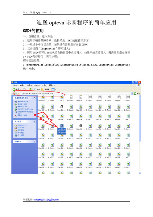
迪堡opteva诊断程序的简单应用OSD+的使用一、使用范围,进入方法1、适用于硬件故障诊断、数据采集、AMI的配置等方面;2、一般设备中均已安装,如果没有需要重新安装OSD+;3、双击桌面“Diagnostics”即可进入;4、调用OSD+都可以直接从后台操作员中直接调入,如果不能直接调入,则需要从指定路径1)OSD+程序即可,调用步骤:程序的路径是:C:\ProgramFiles\Diebold\AMI\Diagnostics\Bin\Diebold.AMI.Diagnostics.Diagnostics 选中双击:2)选择:“yes”即可进入进入后看到的画面:正常的话都是蓝色的。
PS:因为没有模块所以基本都是红色的。
二、 Terminal Pages▪Terminal Status 列出设备上所有模块的状态,用户可以选择任何一个模块进入诊断。
也可以直接点击机器上面的“对号”和“错号”。
▪Modules –显示了终端上所有的模块及其可以使用的测试项目。
▪Self Tests –自检,可在任意模块或所有模块上运行。
▪Version Info –显示了终端上所有软件和硬件的版本信息。
▪Configuration and Capabilities 配置及性能,可更改AMI参数▪Metrics –显示终端上所有模块的统计信息,根据需要可打印在凭条上带回。
▪Status Log –显示终端上模块的历史状态信息。
1、Terminal Status 绿色√:模块完全正常;红色X:模块全部或其部分不能正常操作;黄色!:模块报警,例如缺纸或缺钞。
2、Module and Module State List-模块和模块状态列表模块用四种颜色字体显示,分别表示为绿:模块正常;红:模块不可用,需要注意;黄:模块报警,需要人为干预;黑:模块尚未安装3、Module States-模块状态(一)Hardware Clear Required –模块需要清洁或需要维护;可能的原因例如模块卡钞、卡纸,或需要重新加钞。
Moxa EDS-P308 Series与SPL-24快速安装指南说明书

P/N: 1802003080015*1802003080015*EDS-P308 Series & SPL-24 Quick Installation GuideMoxa EtherDevice TM Switch & PoE SplitterEdition 6.0, February 2017Technical Support Contact Information/support Moxa Americas:Toll-free: 1-888-669-2872Tel: 1-714-528-6777Fax: 1-714-528-6778 Moxa China (Shanghai office): Toll-free: 800-820-5036 Tel: +86-21-5258-9955 Fax: +86-21-5258-5505 Moxa Europe:Tel: +49-89-3 70 03 99-0Fax: +49-89-3 70 03 99-99 Moxa Asia-Pacific: Tel: +886-2-8919-1230 Fax: +886-2-8919-1231 Moxa India:Tel: +91-80-4172-9088Fax: +91-80-4132-10452017 Moxa Inc. All rights reserved.OverviewWe describe two products in this manual:The Moxa EtherDevice™ EDS-P308 Series is an 8-port smart Ethernet switch that provides an economical solution for your Ethernet connections. The switch supports PoE (Power-over-Ethernet) on ports 1 to 4, which means that the EDS-P308 Series can double as a piece of power source equipment (PSE). When used in this way, the EDS-P308 Series can supply up to 15.4 watts of power per port, and can power IEEE 802.3af compliant powered devices (PD), eliminating the need for additional wiring. The EDS-P308 Series switch is highly versatile, and its FX fiber port can transmit data up to 40 km from the device to the control center with high EMI immunity. As an added bonus, the built-in smart alarm function helps system maintainers monitor the health of your Ethernet network.The SPL-24 plays the role of PD, and splits the data signal and power signal that are transmitted from the PSE. The SPL-24 plays a dual role of providing power to industrial devices, and enabling Ethernet connections. The EDS-P308 and SPL-24 have a wide operating temperature range of -40 to 75°C, and are designed to withstand a high degree of vibration and shock. The rugged hardware design makes the EDS-P308 Series and SPL-24 perfect for ensuring that your Ethernet equipment can operate in critical industrial environments, such as in hazardous locations, and complies with FCC and CE standards.The installation of the EDS-P308 Series is presented on pages 3 to 11. The installation of the SPL-24 is presented on pages 11 to 15.NOTE Throughout this Hardware Installation Guide, we use EDS as an abbreviation for Moxa EtherDevice Switch, and we use SPL as anabbreviation for Moxa PoE Splitter:EDS = Moxa EtherDevice SwitchSPL = Moxa PoE SplitterWiring RequirementsYou should also pay attention to the following items:•Use separate paths to route wiring for power and devices. If power wiring and device wiring paths must cross, make sure the wires are perpendicular at the intersection point.NOTE: Do not run signal or communications wiring and power wiring in the same wire conduit. To avoid interference, wires with different signal characteristics should be routed separately.•You can use the type of signal transmitted through a wire to determine which wires should be kept separate. The rule of thumb is that wiring that shares similar electrical characteristics can bebundled together.•Keep the input wiring and the output wiring separated.•It is strongly advised that you label the wiring to all devices in the system when necessary.Package Checklist for EDS-P308 SeriesThe Moxa EDS-P308 Series is shipped with the following items. If any of these items is missing or damaged, please contact your customer service representative for assistance.•Moxa EtherDevice™ Switch EDS-P308•Protective caps for unused ports•Quick installation guide (printed)•Warranty cardFeatures of EDS-P308 SeriesHigh Performance Network Switching Technology•10/100BaseT(X) (RJ45)•100BaseFX (SC type, Multi/Single mode)•IEEE802.3/802.3u/802.3x 100BaseFX (SC type, multi-mode, and single-mode)•Store and Forward switching process type, with 1024 address entries •10/100M, Full/Half-Duplex, MDI/MDIX auto-sensing•Provides up to 15.4 watts per PoE port•Active circuit protection•Auto disconnection for over voltage or under voltage•Power consumption detection and classificationIndustrial Grade Reliability•Power failure, port break alarm by relay output•Redundant dual DC power inputsRugged Design•Operating temperature range from 0 to 60°C, or extended operating temperature from -40 to 75°C for “-T” models•IP30, rugged high-strength case•DIN-Rail or panel mounting abilitySpecifications of EDS-P308 SeriesEDS-P308 Series Panel Layout1.Grounding screw Array2.Terminal block for power inputsPWR1, PWR2, and relay output3.Heat dissipation orifices4.DIP switches5.Power input PWR1 LED6.Power input PWR2 LED7.Fault LED8.10/100BaseT(X) Port9.TP port’s 100 Mbps LED10.TP port’s 10 Mbps LED11.Model Name12.Screw holes for wall mounting kit13.DIN-Rail Kit14.PoE port LEDs (ports 1 to 4)EDS-P308 (SC-type) Panel LayoutNOTE:MSC: Multi-Mode SC Connector SSC: Single-Mode SC Connector Product models not shown here: EDS-P308-S-SC is identical toEDS-P308-M-SC.EDS-P308-SS-SC is identical toEDS-P308-MM-SC.1.Grounding screw2.Terminal block for power inputsPWR1, PWR2 and relay output3.Heat dissipation orifices4.DIP switches5.Power input PWR1 LED6.Power input PWR2 LED7.Fault LED8.10/100BaseT(X) Port9.100BaseFX Port (SC type,Multi/Single mode)10.TP port’s 100 Mbps LED11.TP port’s 10 Mbps LED12.FX port's 100 Mbps LED13.Model Name14.Screw holes for wall mounting kit15.DIN-Rail Kit16.PoE port LEDs (ports 1 to 4)Mounting DimensionsUnit = mm (inch)DIN-Rail MountingThe aluminum DIN-Rail attachment plate should already be fixed to the back panel of the EDS-P308 Series when you take it out of the box. If you need to reattach the DIN-Rail attachment plate, make sure the stiff metal spring is situated towards the top, as shown in the figures below. STEP 1: Insert the top of the DIN-Rail into the slot just below the stiff metal spring.STEP 2:The DIN-Rail attachment unit will snap into place as shown below.To remove the Moxa EtherDevice Switch from the DIN-Rail, simply reverse Steps 1 and 2 above.Wall Mounting (optional)For some applications, you will find it convenient to mount EDS-P308 Series on the wall, as illustrated below.STEP 1:Remove the aluminumDIN-Rail attachment platefrom the EDS-P308’s rearpanel, and then attach thewall mount plates, as shownin the diagram below.STEP 2: Mounting the EDS-P308 on the wall requires 4screws. Use the switch, with wall mount platesattached, as a guide to mark the correct locations of the4 screws. The heads of the screws should be less than6.0 mm in diameter, and the shafts should be less than3.5 mm in diameter, as shown in the figure at the right.NOTE Before tightening the screws into the wall, make sure the screw head and shank size are suitable by inserting the screw into oneof the keyhole-shaped apertures of the wall mounting plates.Do not screw the screws in all the way—leave about 2 mm to allow room for sliding the wall mount panel between the wall and the screws.STEP 3:Once the screws are fixed in the wall,insert the four screw heads through thelarge parts of the keyhole-shapedapertures, and then slide the EDS-P308downwards, as indicated. Tighten the fourscrews for added stability.Grounding the EDS-P308 SeriesGrounding and wire routing help limit the effects of noise due toelectromagnetic interference (EMI). Run the ground connection from the ground screw to the grounding surface prior to connecting devices.EDS-P308 Series’ Redundant Power InputsBoth power inputs can be connected simultaneously to live DC power sources. If one power source fails, the other live source acts as a backup, and automatically supplies all of EDS-P308 Series’s power needs. Wiring the Redundant Power InputsThe top two contacts and the bottom two contacts of the 6-contactterminal block connector on EDS’s top panel are used for EDS’s two DC inputs. Top and front views of one of the terminal block connectors are shown here.STEP 1:Insert the negative/positive DC wires intothe V-/V+ terminals.STEP 2:To keep the DC wires from pulling loose,use a small flat-blade screwdriver totighten the wire-clamp screws on the frontof the terminal block connector.STEP 3:Insert the plastic terminal block connectorprongs into the terminal block receptor,which is located on EDS’s top panel.EDS-P308 Series’ Alarm ContactThe EDS-P308 Series has one alarm contact located on its top panel. For detailed instructions on how to connect the alarm contact power wires to the two middle contacts of the 6-contact terminal block connector, see the Wiring the Alarm Contact section on page 10. A typical scenario would be to connect the Fault circuit to a warning light located in the control room. The light can be set up to switch on when a fault is detected. The alarm contact has two terminals that form a Fault circuit for connecting to an alarm system. The two wires attached to the Fault contacts form an open circuit when (1) EDS has lost power from one of the DC power inputs, or (2) one of the ports for which the corresponding PORT ALARM DIP Switch is set to ON is not properly connected.If neither of these two conditions occurs, the Fault circuit will be closed. EDS-P308 Series’ DIP Switch SettingsON: Enables the corresponding PORT Alarm. Ifthe port’s link fails, the relay will form anopen circuit and the fault LED will light up.Off: Disables the corresponding PORT Alarm. The relay will form a closed circuit and theFault LED will never light up.Wiring the Alarm ContactThe alarm contact consists of the two middle contacts of the terminal block on EDS’s top panel. Refer to below for detailed instructions on how to connect the wires to the terminal block connector, and how to attach the terminal block connector to the terminal block receptor. In thissection, we explain the meaning of the two contacts used to connect the alarm contact.FAULT: The two middle contacts of the6-contact terminal block connector are used todetect both power faults and port faults. Thetwo wires attached to the Fault contacts forman open circuit when:1. EDS has lost power from one of the DCpower inputs.OR2. One of the ports for which thecorresponding PORT ALARM DIP Switch isset to ON is not properly connected.If neither of these two conditions is satisfied,the Fault circuit will be closed.LED IndicatorsThe front panel of the EDS-P308 Series contains several LED indicators. The function of each LED is described in the table below.Package Checklist for SPL-24The Moxa SPL-24 is shipped with the following items. If any of these items is missing or damaged, please contact your customer service representative for assistance.•Moxa PoE Splitter, SPL-24•Quick installation guide (printed)•Warranty cardFeatures of SPL-24High Performance Network Switching Technology•IEEE802.3af compliance•Power/data split from PoE lines using either spare-pairs or data pairs •Support for up to 12.95 W at 24 VDC•Support for up to 15.4 watts per PoE port•Short circuit protection•Auto disconnection for over voltage or under voltage•Power consumption detection and classificationRugged Design•Operating temperature range from 0 to 60°C, or extended operating temperature from -40 to 75°C for “-T” models•IP30, plastic case•DIN-Rail or panel mounting abilitySpecifications of SPL-24SPL-24 Panel Layout1.Heat dissipation orifices2.Terminal block for power input and grounding3.Moxa Logo4.PoE power LED5.DATA-OUT port6.PoE IN port7.DIN-RailMounting DimensionsUnit = mm (inch)DIN-Rail Mounting for SPL-24The plastic DIN-Rail attachment plate should already be fixed to the back panel of SPL-24 when you take it out of the box. If you need to reattach the DIN-Rail attachment plate, make sure the stiff metal spring is situated towards the top, as shown in the figures below.STEP 1: Insert the top of the DIN-Rail into the slot. STEP 2:The DIN-Rail attachment unit will snap into place as shown below.To remove the SPL-24 from theDIN-Rail, insert a flat-blade screwdriver horizontally into the DIN-Railkit under the SPL-24, and then pull itupwards and release SPL-24towards you away from theDIN-Rail.Grounding the SPL-24Grounding and wire routing help limit theeffects of noise due to electromagneticinterference (EMI). Run the right most contactof the 3-contact terminal block to the groundingsurface prior to connecting devices.Wiring the SPL-24’s Power OutputsThe two left-most contacts of the 3-contact terminal block connector on the SPL-24’s top panel are used for 24 VDC output. Top and front views of one of the terminal block connectors are shown here.STEP 1: Array Insert the negative/positive DC wires into the V-/V+terminals.STEP 2:To keep the DC wires from pulling loose, use a smallflat-blade screwdriver to tighten the wire-clampscrews on the front of the terminal block connector.STEP 3:Insert the plastic terminal block connector prongsinto the terminal block receptor, which is located onSPL-24's top panel.Patent /doc/operations/Moxa_Patent_Marking.pdf。
DishPro 21 多卫星切换设备安装指南说明书

Figure1.Point Dish/SignalCheck Switch procedure will run.When it finishes, Installation Summary screen similar to Figure This screen should identify the installed switch should see every satellite location that your system Satellite line,and the word“All”on the Transp and2.Figure2.Installation Summarywith Identified Devicesuse a DishPro compliant splitter,one side of the communications between the receiver and the LNBF,satellite TV signals to pass.You will see an Installationscreen similar to the one shown in Figure3,whichDP Single LNBF as a“Feed.”This is OK because signal from the DP Single LNBF is still being received transponders.See the next section regarding operating withsplitter.Figure3.Installation Summarywithout Identified DevicesInstallation Summary does not show that Check completed successfully as shown in step4,check your cables at the receivers,switches,and LNBFs,andSwitch again.still do not see the Satellite reception verifiedreceiver off and reconnect your it directly to theupgrade your receiver’s software(see your receiver’s for more information).After receiving the upgrade,DP21and run check switch.Figure4.DISH500with DishPro Twin LNBF,DISH300with a Single LNBF,Two DP21Switches,and DishPro Compliant Splitter.Supports two receivers three satellite locations.Figure5.Two DISH300s with Single DishPro LNBFs, DP21Switches,and Two DishPro Compliant Splitters. Supports two receivers from two satellite locations.Figure6.One Dish500with a Twin LNBF,One Dish300 with a Single LNBF,and One DP21Switch.Supports one receiver from three satellite locations and one receiver from two satellite locations.13。
Dell PowerVault 122T SDLT 320 自动装带器用户指南说明书
配置自动装带器更新固件运行自动装带器系统测试检索有关自动装带器的信息故障排除取出卡住的磁带自动装带器错误代码2.从自动装带器后面板上的接头处拔掉电源线和 SCSI 电缆。
3.如果可能,请将自动装带器从座架插槽中卸下并放在桌子或其它干净、平整的工作台面上。
4.在机架安装结构中,使用螺丝刀将自动装带器两侧用来固定安装支架的前盖螺丝卸下。
在桌面结构中卸下前盖螺丝 — 此结构中没有安装支架。
卸下装配托架(图中左侧所示)5.如果自动装带器带有安装支架(机架安装结构),请卸下自动装带器后面的五颗螺丝以及两侧各一颗附加螺丝,以便松脱自动装带器盖板。
在桌面结构中,卸下前盖螺丝以及结构两侧各三颗附加螺丝。
只卸下图示的后盖螺丝6.将顶盖朝后面滑动,然后再尝试提起顶盖。
7.顶盖挂钩从前面板显示盖边缘松脱后,提起顶盖以将其卸下。
8.直接从自动装带器中将装有您想卸下的每盘磁带的磁带传输器抬起。
9.在每个传输器上,小心地将磁带锁定杆从传输器中拉开,将磁带滑出传输器。
拉开磁带释放杆10.从所需传输器上取出磁带后,将每一传输器再重新装到自动装带器传送带上(参见“安装传输器”)。
11.确保传输器底部的滚轮对准传输器轨道。
12.确保已将每个传输器下的传送带杆插入正确的自动装带器传送带环中。
安装传输器警告:为防止受伤,请在卸下自动装带器盖之前先断开电源和 SCSI 电缆,手指不要靠近风扇。
注释:要取出导入/导出插槽正前方的传输器,请按逆时针方向轻轻转动传送带,移动传送带或传输器,直到该传输器不再位于导入/导出插槽前方。
注释:传送带上有未使用的环。
正确的传送带环在环外有一个多余的突起(参见“安装传输器”)。
将磁带传输器底部的插销插入传送带的插槽中,然后将磁带传输器轻轻转动到位以使其锁定在传送带中。
轻轻按住传输器顶部并来回滑动,确保将传输器正确安装在传送带上。
传输器若已正确连接到传动带上,就不会移动。
如果再移动,则需要重新安装传输器。
ADL USB-DIO-32设备说明书

Embedded SolutionsMODEL USB-DIO-32USER MANUALFILE: USB-DIO-32.A1d ADL Embedded Solutions Inc., 4411 Morena Blvd., Suite 101, San Diego, CA 92117-4345P. +1 858 490-0597 F. +1 858 490-0599e-mail: *****************; web: NoticeThe information in this document is provided for reference only. ADL Embedded Solutions Inc. does not assume any liability arising out of the application or use of the information or products described herein. This document may contain or reference information and products protected by copyrights or patents and does not convey any license under the patent rights of ADL Embedded Solutions Inc., nor the rights of others.IBM PC, PC/XT, and PC/AT are registered trademarks of the International Business Machines Corporation. Printed in USA. Copyright 2001, 2006 by ADL Embedded Solutions Inc., 4411 Morena Blvd. Suite 101, San Diego, CA 92117. All rights reserved.WARNING!!ALWAYS CONNECT AND DISCONNECT YOUR FIELD CABLING WITH THE COMPUTER POWER OFF. ALWAYS TURN COMPUTER POWER OFF BEFORE INSTALLING A CARD. CONNECTING AND DISCONNECTING CABLES, OR INSTALLING CARDS INTO A SYSTEM WITH THE COMPUTER OR FIELD POWER ON MAY CAUSE DAMAGE TO THE I/O CARD AND WILL VOID ALL WARRANTIES, IMPLIED OR EXPRESSED.Table of ContentsChapter 1: Introduction (4)Specifications (6)Figure 1-1: Block Diagram (8)Chapter 2: Installation (9)Chapter 3: Hardware Details (10)Figure 3-1: Option Selection Map (10)Chapter 4: USB Address Information (12)Chapter 5: Programming (13)Chapter 6: 8254 Counter/Timer (14)Chapter 7: Connector Pin Assignments (16)Table 7-1: 50-Pin Connector Pin Assignments (16)Chapter 1: IntroductionFeatures•32 lines of digital I/O•High-speed USB 2.0 device, USB 1.1 backwards compatible•Four 8-bit ports independently selectable for inputs or outputs•All 32 I/O lines buffered with 32 mA source, 64mA sink current capabilities•Three 82C54 counters capable of event counting, frequency measurement, pulse width measurement, or frequency generation•Terminal block adapter card for easy wiring•I/O Buffers can be enabled or tri-stated under program control•Jumper selectable I/O pulled up to 5V for contact monitoring or pulled down to ground •Jumper selectable power provided via USB cable or external power supply for higher current capabilities•Resettable fused +5VDC output•Standard 50pin IDC type connector with key•PC/104 size (3.550 by 3.775 in.)•Rugged industrial enclosure•Compatible with Industry-Standard I/O Racks such as Gordos, OPTO22, Potter & Brumfield, etc.with optional cableApplications•Automatic Test SystemsAutomation•Laboratory•Robotics•MachineControl•Security Systems, Energy Management•Relay Monitoring and Control•Parallel Data Transfer to PC•Sensing Switch Closures or TTL, DTL, CMOS Logic•Driving Indicator Lights or RecordersFUNCTIONAL DESCRIPTIONThis USB board is an ideal solution for adding portable, easy-to-install digital I/O and countercapabilities to any computer with a USB port. The board is a USB 2.0 high speed device, offering thefastest speed available with the USB bus. It is fully compatible with both USB 1.1 and USB 2.0 ports.The card is plug-and-play allowing quick connect/disconnect whenever you need additional I/O on your USB port.The board features 32 bits of TTL-compatible digital I/O with high-current capabilities and three 82C54 counters. Each digital port can be programmed to accept inputs or to drive outputs on four 8-bit ports, designated as port A, B, C, and D. Power is supplied to the card via the USB cable or for higher current capabilities, external power may be used. The I/O wiring connections are via an industry standard 50-pin connector or via a terminal block adapter card. For external circuits, fused +5VDC power is available at the connector. The resettable fuse is rated at 0.5A.All I/O lines are buffered by a type 74ABT245 tristate buffer transceiver capable of sourcing 32 mA orsinking 64 mA. The buffers are configured under program control for input or output. Jumper selectable pull-ups (to +5 VDC) or pull-downs (to ground) on the card allow for contact monitoring and assure that there are no erroneous outputs at power-up until the card is initialized by system software. This jumper can be removed to provide a floating state for the I/O when it is neither pulled up nor down.Unlike most USB digital I/O products which primarily use a human interface device (HID) driver, we provide an easy to use, Windows-based, custom function driver optimized for maximum data throughput. This approach exposes the full functionality of the hardware along with maximizing the advantage of using the high-speed USB 2.0 bus.The board is designed to be used in rugged industrial environments but is small enough to fit nicely onto any desk or testing station. The board is PC/104 size (3.550 by 3.775 inches) and ships inside a steel powder-coated enclosure with an anti-skid bottom.COUNTER/TIMERSAvailable on the board are three 82C54 counters that each include three 16-bit counter/timers factory configured in an optimal module for use as event counters, frequency output, pulse width, and frequency measurement (see the Block Diagram at the end of this chapter).SpecificationsDigital Inputs (TTL Compatible)• Logic High: 2.0 VDC min, 5.5 VDC max• Logic Low: 0.8 VDC max, -0.5 VDC minDigital Outputs• Logic High: 2.0 VDC min., source 32 mA• Logic Low: 0.55 VDC max., sink 64 mACounter/Timers• Type: 82C54-10 programmable interval counters• Output Drive: 2.0 VDC min., source 32 mA0.55 VDC max., sink 64 mA• Maximum Input Frequency: 10MHz• Input Gate: TTL/CMOS compatible• Clock: On-board, 3 MHz crystal-controlled clock• Active Count Edge: Negative edge• Minimum Clock Pulse Width: 30 ns high, 40 ns low• Timer Range: 16 bitsBus Type• USB2.0 high-speed (480 Mb/s)Power• Basic unit: 80 mA typical (no load)• +5 VDC from the USB bus or external power supply depending on user configuration. The USB bus is specified to provide 500 mA to most desktop environments. This gives you 420 mAavailable (500mA -80mA = 420mA). If using more than a total of 500mA, use optional 9 VDC(on board voltage regulator outputs +5 VDC to card) external power supply and remove VUSB jumper and place jumper on VEXT. Then plug in external power before plugging into USB port .This option will give you a total of 1000mA available.• +5V resettable fuse at 0.5A located on connector.Environmental• Operating Temperature Range: 0 °C. to 70 °C.• Storage Temperature Range: -40 °C. to +85 °C.• Humidity: 0 to 90% RH, non-condensing.• Board Dimension: 3.550 x 3.775 inches.• Box Dimension: 4.00 x 4.00" x 1.25 inches.Figure 1-1: Block DiagramChapter 2: InstallationSoftware CD InstallationThese paragraphs are intended to detail the software installation steps as well as describe what is being installed.The software provided with this board is contained on one CD and must be installed onto your hard disk prior to use. To do this, perform the following steps as appropriate for your software format and operating system. Substitute the appropriate drive letter for your CD-ROM or disk drive where you seeG in the examples below.WIN95/98/Me/NT/2000/XP/2003a. Place the CD into your CD-ROM drive.b. The CD should automatically run the install program. If the install program does not clickSTART | RUN and type G LQVWDOO, click OK or press ..c. Follow the on-screen prompts to install the software for this board.Hardware InstallationThe board can be installed in any USB 2.0 or USB 1.1 port. Please refer to the USB I/O Quick Start Guide which can be found on the CD, for specific, quick steps to complete the hardware and software installation.Chapter 3: Hardware DetailsOption SelectionsRefer to the setup programs on the CD provided with the board. Also, refer to the Block Diagram and the Option Selection Map when reading this section of the manual.Figure 3-1: Option Selection MapUSB CONNECTORThe USB connector is a Type B connector and mates with the cable provided. The USB port provides communication signals along with +5 VDC power. The board can be powered from the USB port or, if needed for higher current applications, an external power supply can be used.LEDThe LED on the front of the enclosure is used to indicate power and data transmissions. When the LED is in an illuminated steady green state, this signifies that the board is successfully connected to the computer and has been detected and configured by the operating system. When the LED flashes continuously, this signifies that there is data being transmitted over the USB bus.DC POWER JACK (OPTIONAL)This is an option for high current applications when more current is needed than what your computer can provide on the USB port (typically 500 mA). The DC jack has a 2.00mm post on board and is designed to be used with the 9 VDC AC/DC external power supply that ships with this option. The voltage regulator on board regulates the 9 VDC and provides 5 VDC to the onboard circuitry. When using external power, switch the jumper located near the USB connector to VEXT, otherwise when the jumper is in the VUSB position current is drawn from the USB port (please consult the option selection map for a visual reference).50 PIN BOX HEADERThe 50 pin box header has standard .100" spacing between pins and is keyed to prevent improper connections. It can be used with standard IDC type ribbon cables or the screw terminal board that plugs directly into the box header.Chapter 4: USB Address InformationUse the provided driver to access the USB board. This driver will allow you to determine how many supported USB devices are currently installed, and each device’s type. This information is returned as a Vendor ID (VID), Product ID (PID) and Device Index.The board’s VID is “0x1605", and its PID is “0x8001".The Device Index is determined by how many of the device you have in your system, and provides a unique identifier allowing you to access a specific board at will.Chapter 5: ProgrammingThe driver software provided with the board uses a 32-bit .dll front end compatible with any Windows programming language. Samples provided in Borland C++Builder, Borland Delphi, Microsoft Visual Basic, and Microsoft Visual C++ demonstrate the use of the driver.The following functions are provided by the driver in Windows.These functions will allow you to read or write individual bits, bytes, or the entire board worth of data. In addition, counter-timer functionality and board-level functions complete the driver package.For detailed information on each function refer to the .html Driver Manual located in the Win32 directory for this board.unsigned long GetDevices(void )unsigned long QueryDeviceInfo(DeviceIndex, pPID, pName, pDIOBytes, pCounters)unsigned long DIO_Configure(DeviceIndex, bTristate, pOutMask, pData)unsigned long DIO_Write1(DeviceIndex, BitIndex, bData)unsigned long DIO_Write8(DeviceIndex, ByteIndex, Data)unsigned long DIO_WriteAll(DeviceIndex,pData)unsigned long DIO_Read8(DeviceIndex, ByteIndex,pBuffer)unsigned long DIO_ReadAll(DeviceIndex,Buffer)unsigned long CTR_8254Mode(DeviceIndex, BlockIndex, CounterIndex, Mode)unsigned long CTR_8254ModeLoad(DeviceIndex, BlockIndex, CounterIndex,Mode, LoadValue)unsigned long CTR_8254ReadModeLoad(DeviceIndex, BlockIndex, CounterIndex, Mode, LoadValue , pReadValue)unsigned long CTR_8254Read(DeviceIndex, BlockIndex, CounterIndex, pReadValue)unsigned long CTR_StartOutputFreq(DeviceIndex, CounterIndex, pHz)Chapter 6: 8254 Counter/TimerThese boards have the option of one, two, or three 82C54 counter(s) that each include three 16-bit counter/timers factory configured in an optimal module for use as event counters, frequency output, pulse width, and frequency measurement (See Block Diagram). Each counter can be programmed to any count as low as 1 or 2, and up to 65,536, depending on the mode chosen. For those interested in more detailed information, a full description can be found in the Intel (or equivalent manufacturer's) data sheet, provided in the /chipdocs directory on the Software Master CD.Refer to Chapter 5: Programming, and the .html Driver Manual document installed by the Software Master CD for information on using the installed software driver for this board. The following data is provided only for reference, as it is unlikely to be needed when using the provided driver. Please note the block diagram description of how the 9 pins associated with 8254 counters are configured into an optimum counter-timer module on this board.Operational ModesThe 8254 modes of operation are described in the following paragraphs to familiarize you with the versatility and power of this device. For those interested in more detailed information, a full description of the 8254 programmable interval timer can be found in the Intel (or equivalent manufacturers') data sheets. The following conventions apply for use in describing operation of the 8254 :Clock: A positive pulse into the counter's clock inputTrigger: A rising edge input to the counter's gate inputCounter Loading: Programming a binary count into the counterMode 0: Pulse on Terminal CountAfter the counter is loaded, the output is set low and will remain low until the counter decrements to zero. The output then goes high and remains high until a new count is loaded into the counter. A trigger enables the counter to start decrementing.Mode 1: Retriggerable One-ShotThe output goes low on the clock pulse following a trigger to begin the one-shot pulse and goes high when the counter reaches zero. Additional triggers result in reloading the count and starting the cycle over. If a trigger occurs before the counter decrements to zero, a new count is loaded. This forms a retriggerable one-shot. In mode 1, a low output pulse is provided with a period equal to the counter count-down time.Mode 2: Rate GeneratorThis mode provides a divide-by-N capability where N is the count loaded into the counter. When triggered, the counter output goes low for one clock period after N counts, reloads the initial count, and the cycle starts over. This mode is periodic, the same sequence is repeated indefinitely until the gate input is brought low. This mode also works well as an alternative to mode 0 for event counting.Mode 3: Square Wave GeneratorThis mode operates like mode 2. The output is high for half of the count and low for the other half. If the count is even, then the output is a symmetrical square wave. If the count is odd, then the output is high for (N+1)/2 counts and low for (N-1)/2 counts. Periodic triggering or frequency synthesis are two possible applications for this mode. Note that in this mode, to achieve the square wave, the counterdecrements by two for the total loaded count, then reloads and decrements by two for the second part of the wave form.Mode 4: Software Triggered StrobeThis mode sets the output high and, when the count is loaded, the counter begins to count down. When the counter reaches zero, the output will go low for one input period. The counter must be reloaded to repeat the cycle. A low gate input will inhibit the counter.Mode 5: Hardware Triggered StrobeIn this mode, the counter will start counting after the rising edge of the trigger input and will go low for one clock period when the terminal count is reached. The counter is retriggerable. The output will not go low until the full count after the rising edge of the trigger.Chapter 7: Connector Pin AssignmentsA 50-pin connector provided on the back plate of these boards for I/O connections. Connector pinassignments are listed below.Table 7-1: 50-Pin Connector Pin AssignmentsPin Function Pin Function1C7 2 COUNTER A0 INA13 C64 GATEA25 C56 OUT7 C48 COUNTER B0 INB19 C310 GATEB211 C212 OUT13 C114 COUNTER C0 INC115 C016 GATEC217 B718 OUT19 B6 20 D721 B522 D623 B424 GROUND25 B326 D527 B228 GROUND29 B130 D431 B032 GROUND33 A734 D335 A636 D237 A538 D239 A440 GROUND41 A342 D143 A244 GROUND45 A146 D047 A048 GROUND49 +5V VDC50GROUNDCustomer CommentsIf you experience any problems with this manual or just want to give us some feedback, please email us at: *****************. Please detail any errors you find and include your mailing address so that we can send you any manual updates.Embedded SolutionsADL Embedded Solutions Inc., 4411 Morena Blvd., Suite 101, San Diego, CA 92117-4345P. +1 858 490-0597 F. +1 858 490-0599e-mail: *****************; web: 。
Opteva 368TTW安装尺寸

一、Opteva 368现场安装参考图 1 46厘米(装修后应留的净尺寸) 5 1.5厘米 2 96厘米(装修后应留的净尺寸) 7 68厘米(适合室内外地面水平) 4 30厘米(含装饰部分的尺寸) 8 墙洞 说明: 1.推荐尺寸充分考虑了取款人操作舒适性,但必须在ATM安装地面砌一个水泥墩,水泥墩尺寸为650mm(宽)*150mm(高)*1400mm(墙洞外边沿到后面) 。
2.以上①②⑦三个尺寸误差正负1CM; 3.要求墙洞内壁距后面保留220厘米,左右各50厘米的空间,以便日常操作和维护; 4.OPTEVA 368一体机重约700kg,要求安装地面足够结实。
注: 保险柜底部有调平脚(四颗可升降的六角头螺丝)。
根据需要使用调平脚或升高ATM安装地面的地板高度。
调平脚升出高度不能超过10厘米(包括调平脚六角头)。
二、环境、供电等要求 1.外部电源配置要求 n使用220V市电,电压为220 VAC (± 10%),频率为50 (± 0.5) Hz,左零右相,零线与火线不能接反。
n用户必须单独打地线,采用以中线代替地线的接法(即零线与地线直接短接)是不能接受的。
n必须从配电室配置专用电源,不能与其他大容量感性用电器如空调、马达等共用同一电源。
另外,要求安装快速断电安全装置,如断电保护器,断电电流为10A。
n必须安装容量为2KVA以上的UPS。
n与OPTEVA 328相连的调制解调器、路由器等设备,其电源和地线应符合相同的标准。
n 2.气候标准 n迪堡OPTEVA 368只可用于自助银行内穿墙,也可用于室外穿墙。
n环境要求 (设备工作的室内) 温度:10°C-38°C 相对湿度(非凝聚态): 32°C时:20%-80% 38°C时:20%-55% 3.现场安装场地的要求 n用户在现场装机施工时,按照迪堡提供的安装尺寸图和说明书进行安装,安装时要留有足够的维护空间,以备日常操作和维护之用; n安装时需考虑温、湿度和通风问题,如安装排风扇、布置通风对流口等,不要将机器安装在密封房间内或通风口。
ThinkSystem DS系列和DS EXP D3284硬件安装与维护指南说明书

ThinkSystem DS系列和 DS EXP/D3284硬件安装与维护指南机器类型:4619/4617/4599/4588/6413固件版本:G265第一版(2018 年 2 月)© Copyright Lenovo 2018有限权利声明:如果数据或软件依照美国总务署(GSA)合同提供,则其使用、复制或披露将受到 GS-35F-05925 号合同的约束。
Lenovo、Lenovo 徽标、BladeCenter、DS 系列、Flex System、NeXtScale System、System x 和 ThinkSystem 是 Lenovo 在美国和/或其他国家或地区的商标。
其他公司、产品或服务名称可能是其他公司的商标或服务标记。
本信息中可能包含技术方面不够准确的地方或印刷错误。
此处的信息将定期更改;这些更改将编入本资料的新版本中。
Lenovo 可以随时对本出版物中描述的产品和/或程序进行改进和/或更改,而不另行通知。
目录关于本指南. . . . . . . . . . . . . . . . . . . . . . . . . . . . . . . . . . . . . . . . . . . . . . . . . . . . . . . . . . . . . . . . . . . . . 12简介. . . . . . . . . . . . . . . . . . . . . . . . . . . . . . . . . . . . . . . . . . . . . . . . . . . . . . . . . . . . . . . . . . . . . . . . . . . . . . . . . . . . . . . . . . . . . . . . . . . . . . . . . . 12 DS6200/DS4200/DS2200 机柜用户界面 . . . . . . . . . . . . . . . . . . . . . . . . . . . . . . . . . . . . . . . . . . . . . . . . . . . . . . . . . . . . . . . . . . 12用于主机连接的 CNC 端口. . . . . . . . . . . . . . . . . . . . . . . . . . . . . . . . . . . . . . . . . . . . . . . . . . . . . . . . . . . . . . . . . . . . . . . . . . . . . . . 13用于主机连接的 HD Mini SAS 端口. . . . . . . . . . . . . . . . . . . . . . . . . . . . . . . . . . . . . . . . . . . . . . . . . . . . . . . . . . . . . . . . . . . . . . . 13目标读者. . . . . . . . . . . . . . . . . . . . . . . . . . . . . . . . . . . . . . . . . . . . . . . . . . . . . . . . . . . . . . . . . . . . . . . . . . . . . . . . . . . . . . . . . . . . . . . . . . . . . 13先决条件. . . . . . . . . . . . . . . . . . . . . . . . . . . . . . . . . . . . . . . . . . . . . . . . . . . . . . . . . . . . . . . . . . . . . . . . . . . . . . . . . . . . . . . . . . . . . . . . . . . . . 14相关文档. . . . . . . . . . . . . . . . . . . . . . . . . . . . . . . . . . . . . . . . . . . . . . . . . . . . . . . . . . . . . . . . . . . . . . . . . . . . . . . . . . . . . . . . . . . . . . . . . . . . . 14文档约定与符号. . . . . . . . . . . . . . . . . . . . . . . . . . . . . . . . . . . . . . . . . . . . . . . . . . . . . . . . . . . . . . . . . . . . . . . . . . . . . . . . . . . . . . . . . . . . . 15 1安全准则 . . . . . . . . . . . . . . . . . . . . . . . . . . . . . . . . . . . . . . . . . . . . . . . . . . . . . . . . . . . . . . . . . . . . . . . 16安全搬运. . . . . . . . . . . . . . . . . . . . . . . . . . . . . . . . . . . . . . . . . . . . . . . . . . . . . . . . . . . . . . . . . . . . . . . . . . . . . . . . . . . . . . . . . . . . . . . . . . . . . 16操作. . . . . . . . . . . . . . . . . . . . . . . . . . . . . . . . . . . . . . . . . . . . . . . . . . . . . . . . . . . . . . . . . . . . . . . . . . . . . . . . . . . . . . . . . . . . . . . . . . . . . . . . . . 16电气安全. . . . . . . . . . . . . . . . . . . . . . . . . . . . . . . . . . . . . . . . . . . . . . . . . . . . . . . . . . . . . . . . . . . . . . . . . . . . . . . . . . . . . . . . . . . . . . . . . . . . . 17机架系统安全注意事项 . . . . . . . . . . . . . . . . . . . . . . . . . . . . . . . . . . . . . . . . . . . . . . . . . . . . . . . . . . . . . . . . . . . . . . . . . . . . . . . . . . . . . 18 2系统概述 . . . . . . . . . . . . . . . . . . . . . . . . . . . . . . . . . . . . . . . . . . . . . . . . . . . . . . . . . . . . . . . . . . . . . . . 19机柜配置. . . . . . . . . . . . . . . . . . . . . . . . . . . . . . . . . . . . . . . . . . . . . . . . . . . . . . . . . . . . . . . . . . . . . . . . . . . . . . . . . . . . . . . . . . . . . . . . . . . . . 19高速缓存. . . . . . . . . . . . . . . . . . . . . . . . . . . . . . . . . . . . . . . . . . . . . . . . . . . . . . . . . . . . . . . . . . . . . . . . . . . . . . . . . . . . . . . . . . . . . . . . . . . . . 19 CompactFlash. . . . . . . . . . . . . . . . . . . . . . . . . . . . . . . . . . . . . . . . . . . . . . . . . . . . . . . . . . . . . . . . . . . . . . . . . . . . . . . . . . . . . . . . . . . . . . . . . 19超级电容器组 . . . . . . . . . . . . . . . . . . . . . . . . . . . . . . . . . . . . . . . . . . . . . . . . . . . . . . . . . . . . . . . . . . . . . . . . . . . . . . . . . . . . . . . . . . . . . . . 19机柜变体. . . . . . . . . . . . . . . . . . . . . . . . . . . . . . . . . . . . . . . . . . . . . . . . . . . . . . . . . . . . . . . . . . . . . . . . . . . . . . . . . . . . . . . . . . . . . . . . . . . . 23 2U12. . . . . . . . . . . . . . . . . . . . . . . . . . . . . . . . . . . . . . . . . . . . . . . . . . . . . . . . . . . . . . . . . . . . . . . . . . . . . . . . . . . . . . . . . . . . . . . . . . . . . . 23 2U24 . . . . . . . . . . . . . . . . . . . . . . . . . . . . . . . . . . . . . . . . . . . . . . . . . . . . . . . . . . . . . . . . . . . . . . . . . . . . . . . . . . . . . . . . . . . . . . . . . . . . . 23 D3284. . . . . . . . . . . . . . . . . . . . . . . . . . . . . . . . . . . . . . . . . . . . . . . . . . . . . . . . . . . . . . . . . . . . . . . . . . . . . . . . . . . . . . . . . . . . . . . . . . . . 23 2U 机柜核心产品 . . . . . . . . . . . . . . . . . . . . . . . . . . . . . . . . . . . . . . . . . . . . . . . . . . . . . . . . . . . . . . . . . . . . . . . . . . . . . . . . . . . . . . . . . . . 24 2U 机柜前面板 . . . . . . . . . . . . . . . . . . . . . . . . . . . . . . . . . . . . . . . . . . . . . . . . . . . . . . . . . . . . . . . . . . . . . . . . . . . . . . . . . . . . . . . . . . 24 2U 机柜后面板 . . . . . . . . . . . . . . . . . . . . . . . . . . . . . . . . . . . . . . . . . . . . . . . . . . . . . . . . . . . . . . . . . . . . . . . . . . . . . . . . . . . . . . . . . . 25 2U 机柜机箱 . . . . . . . . . . . . . . . . . . . . . . . . . . . . . . . . . . . . . . . . . . . . . . . . . . . . . . . . . . . . . . . . . . . . . . . . . . . . . . . . . . . . . . . . . . . . . . . . 28 5U 机柜核心产品 . . . . . . . . . . . . . . . . . . . . . . . . . . . . . . . . . . . . . . . . . . . . . . . . . . . . . . . . . . . . . . . . . . . . . . . . . . . . . . . . . . . . . . . . . . . 30 5U 机柜前面板 . . . . . . . . . . . . . . . . . . . . . . . . . . . . . . . . . . . . . . . . . . . . . . . . . . . . . . . . . . . . . . . . . . . . . . . . . . . . . . . . . . . . . . . . . . . 31 5U 机柜后面板 . . . . . . . . . . . . . . . . . . . . . . . . . . . . . . . . . . . . . . . . . . . . . . . . . . . . . . . . . . . . . . . . . . . . . . . . . . . . . . . . . . . . . . . . . . 32 5U 机柜机箱 . . . . . . . . . . . . . . . . . . . . . . . . . . . . . . . . . . . . . . . . . . . . . . . . . . . . . . . . . . . . . . . . . . . . . . . . . . . . . . . . . . . . . . . . . . . . . . . . . 33 5U 机柜抽屉. . . . . . . . . . . . . . . . . . . . . . . . . . . . . . . . . . . . . . . . . . . . . . . . . . . . . . . . . . . . . . . . . . . . . . . . . . . . . . . . . . . . . . . . . . . . . . 33操作面板. . . . . . . . . . . . . . . . . . . . . . . . . . . . . . . . . . . . . . . . . . . . . . . . . . . . . . . . . . . . . . . . . . . . . . . . . . . . . . . . . . . . . . . . . . . . . . . . . . . . 34 2U 机柜操作面板. . . . . . . . . . . . . . . . . . . . . . . . . . . . . . . . . . . . . . . . . . . . . . . . . . . . . . . . . . . . . . . . . . . . . . . . . . . . . . . . . . . . . . . . 34 5U 机柜操作面板. . . . . . . . . . . . . . . . . . . . . . . . . . . . . . . . . . . . . . . . . . . . . . . . . . . . . . . . . . . . . . . . . . . . . . . . . . . . . . . . . . . . . . . . 36电源散热模块 — 2U 机柜. . . . . . . . . . . . . . . . . . . . . . . . . . . . . . . . . . . . . . . . . . . . . . . . . . . . . . . . . . . . . . . . . . . . . . . . . . . . . . . . . . . 37 580W PCM . . . . . . . . . . . . . . . . . . . . . . . . . . . . . . . . . . . . . . . . . . . . . . . . . . . . . . . . . . . . . . . . . . . . . . . . . . . . . . . . . . . . . . . . . . . . . . . 37多个 PCM. . . . . . . . . . . . . . . . . . . . . . . . . . . . . . . . . . . . . . . . . . . . . . . . . . . . . . . . . . . . . . . . . . . . . . . . . . . . . . . . . . . . . . . . . . . . . . . . 37系统气流 . . . . . . . . . . . . . . . . . . . . . . . . . . . . . . . . . . . . . . . . . . . . . . . . . . . . . . . . . . . . . . . . . . . . . . . . . . . . . . . . . . . . . . . . . . . . . . . . 38电源模块单元 — 5U 机柜. . . . . . . . . . . . . . . . . . . . . . . . . . . . . . . . . . . . . . . . . . . . . . . . . . . . . . . . . . . . . . . . . . . . . . . . . . . . . . . . . . . 38风扇散热模块 — 5U 机柜. . . . . . . . . . . . . . . . . . . . . . . . . . . . . . . . . . . . . . . . . . . . . . . . . . . . . . . . . . . . . . . . . . . . . . . . . . . . . . . . . . . 39控制器模块和扩展模块 . . . . . . . . . . . . . . . . . . . . . . . . . . . . . . . . . . . . . . . . . . . . . . . . . . . . . . . . . . . . . . . . . . . . . . . . . . . . . . . . . . . . 4012 Gb/s 控制器模块 LED . . . . . . . . . . . . . . . . . . . . . . . . . . . . . . . . . . . . . . . . . . . . . . . . . . . . . . . . . . . . . . . . . . . . . . . . . . . . . . . . . 40单控制器正常工作时的控制器故障. . . . . . . . . . . . . . . . . . . . . . . . . . . . . . . . . . . . . . . . . . . . . . . . . . . . . . . . . . . . . . . . . . . . 4712 Gb/s 扩展模块 LED. . . . . . . . . . . . . . . . . . . . . . . . . . . . . . . . . . . . . . . . . . . . . . . . . . . . . . . . . . . . . . . . . . . . . . . . . . . . . . . . . . . . 48硬盘模块. . . . . . . . . . . . . . . . . . . . . . . . . . . . . . . . . . . . . . . . . . . . . . . . . . . . . . . . . . . . . . . . . . . . . . . . . . . . . . . . . . . . . . . . . . . . . . . . . . . . 49目录35U 机箱中的 DDIC. . . . . . . . . . . . . . . . . . . . . . . . . . . . . . . . . . . . . . . . . . . . . . . . . . . . . . . . . . . . . . . . . . . . . . . . . . . . . . . . . . . . . . . . 52机柜管理. . . . . . . . . . . . . . . . . . . . . . . . . . . . . . . . . . . . . . . . . . . . . . . . . . . . . . . . . . . . . . . . . . . . . . . . . . . . . . . . . . . . . . . . . . . . . . . . . . . . 54管理界面 . . . . . . . . . . . . . . . . . . . . . . . . . . . . . . . . . . . . . . . . . . . . . . . . . . . . . . . . . . . . . . . . . . . . . . . . . . . . . . . . . . . . . . . . . . . . . . . . 54 3安装 . . . . . . . . . . . . . . . . . . . . . . . . . . . . . . . . . . . . . . . . . . . . . . . . . . . . . . . . . . . . . . . . . . . . . . . . . . . 55安装核对表 . . . . . . . . . . . . . . . . . . . . . . . . . . . . . . . . . . . . . . . . . . . . . . . . . . . . . . . . . . . . . . . . . . . . . . . . . . . . . . . . . . . . . . . . . . . . . . . . . 55规划安装. . . . . . . . . . . . . . . . . . . . . . . . . . . . . . . . . . . . . . . . . . . . . . . . . . . . . . . . . . . . . . . . . . . . . . . . . . . . . . . . . . . . . . . . . . . . . . . . . . . . 56为安装做准备. . . . . . . . . . . . . . . . . . . . . . . . . . . . . . . . . . . . . . . . . . . . . . . . . . . . . . . . . . . . . . . . . . . . . . . . . . . . . . . . . . . . . . . . . . . . . . . 56准备站点和主机服务器 . . . . . . . . . . . . . . . . . . . . . . . . . . . . . . . . . . . . . . . . . . . . . . . . . . . . . . . . . . . . . . . . . . . . . . . . . . . . . . . . . 57打开机柜包装 . . . . . . . . . . . . . . . . . . . . . . . . . . . . . . . . . . . . . . . . . . . . . . . . . . . . . . . . . . . . . . . . . . . . . . . . . . . . . . . . . . . . . . . . . . . 57必备工具 . . . . . . . . . . . . . . . . . . . . . . . . . . . . . . . . . . . . . . . . . . . . . . . . . . . . . . . . . . . . . . . . . . . . . . . . . . . . . . . . . . . . . . . . . . . . . . . . 58机架式安装要求. . . . . . . . . . . . . . . . . . . . . . . . . . . . . . . . . . . . . . . . . . . . . . . . . . . . . . . . . . . . . . . . . . . . . . . . . . . . . . . . . . . . . . . . . 58机架式导轨套件 . . . . . . . . . . . . . . . . . . . . . . . . . . . . . . . . . . . . . . . . . . . . . . . . . . . . . . . . . . . . . . . . . . . . . . . . . . . . . . . . . . . . . . . . . . . . 59安装 2U 机柜 . . . . . . . . . . . . . . . . . . . . . . . . . . . . . . . . . . . . . . . . . . . . . . . . . . . . . . . . . . . . . . . . . . . . . . . . . . . . . . . . . . . . . . . . . . . . . . . . 59安装 5U 机柜 . . . . . . . . . . . . . . . . . . . . . . . . . . . . . . . . . . . . . . . . . . . . . . . . . . . . . . . . . . . . . . . . . . . . . . . . . . . . . . . . . . . . . . . . . . . . . . . . 60 FDE 注意事项 . . . . . . . . . . . . . . . . . . . . . . . . . . . . . . . . . . . . . . . . . . . . . . . . . . . . . . . . . . . . . . . . . . . . . . . . . . . . . . . . . . . . . . . . . . . . . . . 61连接控制器机柜和可选扩展机柜 . . . . . . . . . . . . . . . . . . . . . . . . . . . . . . . . . . . . . . . . . . . . . . . . . . . . . . . . . . . . . . . . . . . . . . . . . . 61扩展机柜的线缆要求. . . . . . . . . . . . . . . . . . . . . . . . . . . . . . . . . . . . . . . . . . . . . . . . . . . . . . . . . . . . . . . . . . . . . . . . . . . . . . . . . . . . 62电源线连接 . . . . . . . . . . . . . . . . . . . . . . . . . . . . . . . . . . . . . . . . . . . . . . . . . . . . . . . . . . . . . . . . . . . . . . . . . . . . . . . . . . . . . . . . . . . . . . . . . 65测试机柜连接 . . . . . . . . . . . . . . . . . . . . . . . . . . . . . . . . . . . . . . . . . . . . . . . . . . . . . . . . . . . . . . . . . . . . . . . . . . . . . . . . . . . . . . . . . . . 65接地检查. . . . . . . . . . . . . . . . . . . . . . . . . . . . . . . . . . . . . . . . . . . . . . . . . . . . . . . . . . . . . . . . . . . . . . . . . . . . . . . . . . . . . . . . . . . . . . . . . . . . 66主机系统要求. . . . . . . . . . . . . . . . . . . . . . . . . . . . . . . . . . . . . . . . . . . . . . . . . . . . . . . . . . . . . . . . . . . . . . . . . . . . . . . . . . . . . . . . . . . . . . . 66线缆连接注意事项. . . . . . . . . . . . . . . . . . . . . . . . . . . . . . . . . . . . . . . . . . . . . . . . . . . . . . . . . . . . . . . . . . . . . . . . . . . . . . . . . . . . . . . . . . 66将机柜连接到主机. . . . . . . . . . . . . . . . . . . . . . . . . . . . . . . . . . . . . . . . . . . . . . . . . . . . . . . . . . . . . . . . . . . . . . . . . . . . . . . . . . . . . . . . . . 66 CNC 技术. . . . . . . . . . . . . . . . . . . . . . . . . . . . . . . . . . . . . . . . . . . . . . . . . . . . . . . . . . . . . . . . . . . . . . . . . . . . . . . . . . . . . . . . . . . . . . . . . 67 HD Mini SAS . . . . . . . . . . . . . . . . . . . . . . . . . . . . . . . . . . . . . . . . . . . . . . . . . . . . . . . . . . . . . . . . . . . . . . . . . . . . . . . . . . . . . . . . . . . . . . 68主机连接. . . . . . . . . . . . . . . . . . . . . . . . . . . . . . . . . . . . . . . . . . . . . . . . . . . . . . . . . . . . . . . . . . . . . . . . . . . . . . . . . . . . . . . . . . . . . . . . . . . . 69 Fibre Channel 主机连接 . . . . . . . . . . . . . . . . . . . . . . . . . . . . . . . . . . . . . . . . . . . . . . . . . . . . . . . . . . . . . . . . . . . . . . . . . . . . . . . . . . 69 10GbE iSCSI 主机连接 . . . . . . . . . . . . . . . . . . . . . . . . . . . . . . . . . . . . . . . . . . . . . . . . . . . . . . . . . . . . . . . . . . . . . . . . . . . . . . . . . . . . 691 Gb iSCSI 主机连接 . . . . . . . . . . . . . . . . . . . . . . . . . . . . . . . . . . . . . . . . . . . . . . . . . . . . . . . . . . . . . . . . . . . . . . . . . . . . . . . . . . . . . . 69HD Mini SAS 主机连接 . . . . . . . . . . . . . . . . . . . . . . . . . . . . . . . . . . . . . . . . . . . . . . . . . . . . . . . . . . . . . . . . . . . . . . . . . . . . . . . . . . . 69连接网络上的管理主机. . . . . . . . . . . . . . . . . . . . . . . . . . . . . . . . . . . . . . . . . . . . . . . . . . . . . . . . . . . . . . . . . . . . . . . . . . . . . . . . . . . . . 72更新固件. . . . . . . . . . . . . . . . . . . . . . . . . . . . . . . . . . . . . . . . . . . . . . . . . . . . . . . . . . . . . . . . . . . . . . . . . . . . . . . . . . . . . . . . . . . . . . . . . . . . 72获取 IP 值 . . . . . . . . . . . . . . . . . . . . . . . . . . . . . . . . . . . . . . . . . . . . . . . . . . . . . . . . . . . . . . . . . . . . . . . . . . . . . . . . . . . . . . . . . . . . . . . . . . . 73使用 DHCP 来设置网络端口 IP 地址 . . . . . . . . . . . . . . . . . . . . . . . . . . . . . . . . . . . . . . . . . . . . . . . . . . . . . . . . . . . . . . . . . . . . 73使用 CLI 端口和线缆来设置网络端口 IP 地址 . . . . . . . . . . . . . . . . . . . . . . . . . . . . . . . . . . . . . . . . . . . . . . . . . . . . . . . . . . 73更改 CNC 端口模式. . . . . . . . . . . . . . . . . . . . . . . . . . . . . . . . . . . . . . . . . . . . . . . . . . . . . . . . . . . . . . . . . . . . . . . . . . . . . . . . . . . . . . 76连接两个存储系统以复制卷 . . . . . . . . . . . . . . . . . . . . . . . . . . . . . . . . . . . . . . . . . . . . . . . . . . . . . . . . . . . . . . . . . . . . . . . . . . . . . . . 76用于复制的线缆连接. . . . . . . . . . . . . . . . . . . . . . . . . . . . . . . . . . . . . . . . . . . . . . . . . . . . . . . . . . . . . . . . . . . . . . . . . . . . . . . . . . . . 77 4操作 . . . . . . . . . . . . . . . . . . . . . . . . . . . . . . . . . . . . . . . . . . . . . . . . . . . . . . . . . . . . . . . . . . . . . . . . . . . 80开始前 . . . . . . . . . . . . . . . . . . . . . . . . . . . . . . . . . . . . . . . . . . . . . . . . . . . . . . . . . . . . . . . . . . . . . . . . . . . . . . . . . . . . . . . . . . . . . . . . . . . . . . 80打开/关闭电源. . . . . . . . . . . . . . . . . . . . . . . . . . . . . . . . . . . . . . . . . . . . . . . . . . . . . . . . . . . . . . . . . . . . . . . . . . . . . . . . . . . . . . . . . . . . . 80操作员(操作)面板 LED. . . . . . . . . . . . . . . . . . . . . . . . . . . . . . . . . . . . . . . . . . . . . . . . . . . . . . . . . . . . . . . . . . . . . . . . . . . . . . . . . . 81装置标识号 . . . . . . . . . . . . . . . . . . . . . . . . . . . . . . . . . . . . . . . . . . . . . . . . . . . . . . . . . . . . . . . . . . . . . . . . . . . . . . . . . . . . . . . . . . . . . . . . . 81软件/SES . . . . . . . . . . . . . . . . . . . . . . . . . . . . . . . . . . . . . . . . . . . . . . . . . . . . . . . . . . . . . . . . . . . . . . . . . . . . . . . . . . . . . . . . . . . . . . . . 81硬盘 LED . . . . . . . . . . . . . . . . . . . . . . . . . . . . . . . . . . . . . . . . . . . . . . . . . . . . . . . . . . . . . . . . . . . . . . . . . . . . . . . . . . . . . . . . . . . . . . . . . . . . 81 2U 机箱中使用的磁盘模块. . . . . . . . . . . . . . . . . . . . . . . . . . . . . . . . . . . . . . . . . . . . . . . . . . . . . . . . . . . . . . . . . . . . . . . . . . . . . . 81 4目录5故障诊断和问题解决 . . . . . . . . . . . . . . . . . . . . . . . . . . . . . . . . . . . . . . . . . . . . . . . . . . . . . . . . . . .83概述. . . . . . . . . . . . . . . . . . . . . . . . . . . . . . . . . . . . . . . . . . . . . . . . . . . . . . . . . . . . . . . . . . . . . . . . . . . . . . . . . . . . . . . . . . . . . . . . . . . . . . . . . 83初始启动问题 . . . . . . . . . . . . . . . . . . . . . . . . . . . . . . . . . . . . . . . . . . . . . . . . . . . . . . . . . . . . . . . . . . . . . . . . . . . . . . . . . . . . . . . . . . . . . . 83故障电源线. . . . . . . . . . . . . . . . . . . . . . . . . . . . . . . . . . . . . . . . . . . . . . . . . . . . . . . . . . . . . . . . . . . . . . . . . . . . . . . . . . . . . . . . . . . . . . 83计算机无法识别机柜系统 . . . . . . . . . . . . . . . . . . . . . . . . . . . . . . . . . . . . . . . . . . . . . . . . . . . . . . . . . . . . . . . . . . . . . . . . . . . . . . 83 LED. . . . . . . . . . . . . . . . . . . . . . . . . . . . . . . . . . . . . . . . . . . . . . . . . . . . . . . . . . . . . . . . . . . . . . . . . . . . . . . . . . . . . . . . . . . . . . . . . . . . . . . . . . 83 2U 机柜 LED. . . . . . . . . . . . . . . . . . . . . . . . . . . . . . . . . . . . . . . . . . . . . . . . . . . . . . . . . . . . . . . . . . . . . . . . . . . . . . . . . . . . . . . . . . . . . . . . . 84 580W PCM LED. . . . . . . . . . . . . . . . . . . . . . . . . . . . . . . . . . . . . . . . . . . . . . . . . . . . . . . . . . . . . . . . . . . . . . . . . . . . . . . . . . . . . . . . . . . 84操作面板 LED . . . . . . . . . . . . . . . . . . . . . . . . . . . . . . . . . . . . . . . . . . . . . . . . . . . . . . . . . . . . . . . . . . . . . . . . . . . . . . . . . . . . . . . . . . . 84硬盘支架模块 LED . . . . . . . . . . . . . . . . . . . . . . . . . . . . . . . . . . . . . . . . . . . . . . . . . . . . . . . . . . . . . . . . . . . . . . . . . . . . . . . . . . . . . . 85 IOM LED. . . . . . . . . . . . . . . . . . . . . . . . . . . . . . . . . . . . . . . . . . . . . . . . . . . . . . . . . . . . . . . . . . . . . . . . . . . . . . . . . . . . . . . . . . . . . . . . . . 86 5U 机柜 LED. . . . . . . . . . . . . . . . . . . . . . . . . . . . . . . . . . . . . . . . . . . . . . . . . . . . . . . . . . . . . . . . . . . . . . . . . . . . . . . . . . . . . . . . . . . . . . . . . 87 PSU LED . . . . . . . . . . . . . . . . . . . . . . . . . . . . . . . . . . . . . . . . . . . . . . . . . . . . . . . . . . . . . . . . . . . . . . . . . . . . . . . . . . . . . . . . . . . . . . . . . 88风扇散热模块 LED . . . . . . . . . . . . . . . . . . . . . . . . . . . . . . . . . . . . . . . . . . . . . . . . . . . . . . . . . . . . . . . . . . . . . . . . . . . . . . . . . . . . . . 88操作面板 LED . . . . . . . . . . . . . . . . . . . . . . . . . . . . . . . . . . . . . . . . . . . . . . . . . . . . . . . . . . . . . . . . . . . . . . . . . . . . . . . . . . . . . . . . . . . 88抽屉 LED. . . . . . . . . . . . . . . . . . . . . . . . . . . . . . . . . . . . . . . . . . . . . . . . . . . . . . . . . . . . . . . . . . . . . . . . . . . . . . . . . . . . . . . . . . . . . . . . . 89 DDIC LED. . . . . . . . . . . . . . . . . . . . . . . . . . . . . . . . . . . . . . . . . . . . . . . . . . . . . . . . . . . . . . . . . . . . . . . . . . . . . . . . . . . . . . . . . . . . . . . . . 89 IOM LED. . . . . . . . . . . . . . . . . . . . . . . . . . . . . . . . . . . . . . . . . . . . . . . . . . . . . . . . . . . . . . . . . . . . . . . . . . . . . . . . . . . . . . . . . . . . . . . . . . 89温度传感器. . . . . . . . . . . . . . . . . . . . . . . . . . . . . . . . . . . . . . . . . . . . . . . . . . . . . . . . . . . . . . . . . . . . . . . . . . . . . . . . . . . . . . . . . . . . . . . . . 89 2U 机柜故障诊断 . . . . . . . . . . . . . . . . . . . . . . . . . . . . . . . . . . . . . . . . . . . . . . . . . . . . . . . . . . . . . . . . . . . . . . . . . . . . . . . . . . . . . . . . . . . 90 PCM 故障. . . . . . . . . . . . . . . . . . . . . . . . . . . . . . . . . . . . . . . . . . . . . . . . . . . . . . . . . . . . . . . . . . . . . . . . . . . . . . . . . . . . . . . . . . . . . . . . 90温度监控和控制 . . . . . . . . . . . . . . . . . . . . . . . . . . . . . . . . . . . . . . . . . . . . . . . . . . . . . . . . . . . . . . . . . . . . . . . . . . . . . . . . . . . . . . . . . 91热警报. . . . . . . . . . . . . . . . . . . . . . . . . . . . . . . . . . . . . . . . . . . . . . . . . . . . . . . . . . . . . . . . . . . . . . . . . . . . . . . . . . . . . . . . . . . . . . . . . . . . 91 5U 机柜故障诊断 . . . . . . . . . . . . . . . . . . . . . . . . . . . . . . . . . . . . . . . . . . . . . . . . . . . . . . . . . . . . . . . . . . . . . . . . . . . . . . . . . . . . . . . . . . . . 91温度注意事项. . . . . . . . . . . . . . . . . . . . . . . . . . . . . . . . . . . . . . . . . . . . . . . . . . . . . . . . . . . . . . . . . . . . . . . . . . . . . . . . . . . . . . . . . . . 92 USB CLI 端口连接 . . . . . . . . . . . . . . . . . . . . . . . . . . . . . . . . . . . . . . . . . . . . . . . . . . . . . . . . . . . . . . . . . . . . . . . . . . . . . . . . . . . . . . . . . . . 92故障定位方法 . . . . . . . . . . . . . . . . . . . . . . . . . . . . . . . . . . . . . . . . . . . . . . . . . . . . . . . . . . . . . . . . . . . . . . . . . . . . . . . . . . . . . . . . . . . . . . 92基本步骤 . . . . . . . . . . . . . . . . . . . . . . . . . . . . . . . . . . . . . . . . . . . . . . . . . . . . . . . . . . . . . . . . . . . . . . . . . . . . . . . . . . . . . . . . . . . . . . . . 93执行基本步骤时可用的选项. . . . . . . . . . . . . . . . . . . . . . . . . . . . . . . . . . . . . . . . . . . . . . . . . . . . . . . . . . . . . . . . . . . . . . . . . . . . 93执行基本步骤. . . . . . . . . . . . . . . . . . . . . . . . . . . . . . . . . . . . . . . . . . . . . . . . . . . . . . . . . . . . . . . . . . . . . . . . . . . . . . . . . . . . . . . . . . . 93如果机柜未初始化. . . . . . . . . . . . . . . . . . . . . . . . . . . . . . . . . . . . . . . . . . . . . . . . . . . . . . . . . . . . . . . . . . . . . . . . . . . . . . . . . . . . . . 94更正机柜标识. . . . . . . . . . . . . . . . . . . . . . . . . . . . . . . . . . . . . . . . . . . . . . . . . . . . . . . . . . . . . . . . . . . . . . . . . . . . . . . . . . . . . . . . . . . 95主机 I/O . . . . . . . . . . . . . . . . . . . . . . . . . . . . . . . . . . . . . . . . . . . . . . . . . . . . . . . . . . . . . . . . . . . . . . . . . . . . . . . . . . . . . . . . . . . . . . . . . . . . . 95处理硬件故障 . . . . . . . . . . . . . . . . . . . . . . . . . . . . . . . . . . . . . . . . . . . . . . . . . . . . . . . . . . . . . . . . . . . . . . . . . . . . . . . . . . . . . . . . . . . . . . 95定位主机侧连接故障 . . . . . . . . . . . . . . . . . . . . . . . . . . . . . . . . . . . . . . . . . . . . . . . . . . . . . . . . . . . . . . . . . . . . . . . . . . . . . . . . . . . 95定位控制器模块扩展端口连接故障. . . . . . . . . . . . . . . . . . . . . . . . . . . . . . . . . . . . . . . . . . . . . . . . . . . . . . . . . . . . . . . . . . . . 95定位复制故障. . . . . . . . . . . . . . . . . . . . . . . . . . . . . . . . . . . . . . . . . . . . . . . . . . . . . . . . . . . . . . . . . . . . . . . . . . . . . . . . . . . . . . . . . . . 96更换期间的持续操作. . . . . . . . . . . . . . . . . . . . . . . . . . . . . . . . . . . . . . . . . . . . . . . . . . . . . . . . . . . . . . . . . . . . . . . . . . . . . . . . . . . . . . . 96固件更新. . . . . . . . . . . . . . . . . . . . . . . . . . . . . . . . . . . . . . . . . . . . . . . . . . . . . . . . . . . . . . . . . . . . . . . . . . . . . . . . . . . . . . . . . . . . . . . . . . . . 96客户可更换单元. . . . . . . . . . . . . . . . . . . . . . . . . . . . . . . . . . . . . . . . . . . . . . . . . . . . . . . . . . . . . . . . . . . . . . . . . . . . . . . . . . . . . . . . . . . . 97 CRU 寻址 2U 12 驱动器机箱 . . . . . . . . . . . . . . . . . . . . . . . . . . . . . . . . . . . . . . . . . . . . . . . . . . . . . . . . . . . . . . . . . . . . . . . . . . . . . 98 CRU 寻址 2U 24 驱动器机箱. . . . . . . . . . . . . . . . . . . . . . . . . . . . . . . . . . . . . . . . . . . . . . . . . . . . . . . . . . . . . . . . . . . . . . . . . . . . . 99 CRU 寻址高密度 5U 84 驱动器机箱. . . . . . . . . . . . . . . . . . . . . . . . . . . . . . . . . . . . . . . . . . . . . . . . . . . . . . . . . . . . . . . . . . . . 100 6模块卸下和更换. . . . . . . . . . . . . . . . . . . . . . . . . . . . . . . . . . . . . . . . . . . . . . . . . . . . . . . . . . . . . . .102概述. . . . . . . . . . . . . . . . . . . . . . . . . . . . . . . . . . . . . . . . . . . . . . . . . . . . . . . . . . . . . . . . . . . . . . . . . . . . . . . . . . . . . . . . . . . . . . . . . . . . . . . . 102 ESD 注意事项. . . . . . . . . . . . . . . . . . . . . . . . . . . . . . . . . . . . . . . . . . . . . . . . . . . . . . . . . . . . . . . . . . . . . . . . . . . . . . . . . . . . . . . . . . . . . . 102目录5防止静电释放的接地方法. . . . . . . . . . . . . . . . . . . . . . . . . . . . . . . . . . . . . . . . . . . . . . . . . . . . . . . . . . . . . . . . . . . . . . . . . . . . . . 102更换 2U 机箱的 CRU. . . . . . . . . . . . . . . . . . . . . . . . . . . . . . . . . . . . . . . . . . . . . . . . . . . . . . . . . . . . . . . . . . . . . . . . . . . . . . . . . . . . . . . . 103更换电源散热模块. . . . . . . . . . . . . . . . . . . . . . . . . . . . . . . . . . . . . . . . . . . . . . . . . . . . . . . . . . . . . . . . . . . . . . . . . . . . . . . . . . . . . . . . . 103卸下 PCM . . . . . . . . . . . . . . . . . . . . . . . . . . . . . . . . . . . . . . . . . . . . . . . . . . . . . . . . . . . . . . . . . . . . . . . . . . . . . . . . . . . . . . . . . . . . . . . 103安装 PCM . . . . . . . . . . . . . . . . . . . . . . . . . . . . . . . . . . . . . . . . . . . . . . . . . . . . . . . . . . . . . . . . . . . . . . . . . . . . . . . . . . . . . . . . . . . . . . . 105更换驱动器支架模块 . . . . . . . . . . . . . . . . . . . . . . . . . . . . . . . . . . . . . . . . . . . . . . . . . . . . . . . . . . . . . . . . . . . . . . . . . . . . . . . . . . . . . . 105卸下 LFF 驱动器支架模块. . . . . . . . . . . . . . . . . . . . . . . . . . . . . . . . . . . . . . . . . . . . . . . . . . . . . . . . . . . . . . . . . . . . . . . . . . . . . . 106安装 LFF 驱动器支架模块. . . . . . . . . . . . . . . . . . . . . . . . . . . . . . . . . . . . . . . . . . . . . . . . . . . . . . . . . . . . . . . . . . . . . . . . . . . . . . 107卸下 SFF 驱动器支架模块. . . . . . . . . . . . . . . . . . . . . . . . . . . . . . . . . . . . . . . . . . . . . . . . . . . . . . . . . . . . . . . . . . . . . . . . . . . . . . 108安装 SFF 驱动器支架模块. . . . . . . . . . . . . . . . . . . . . . . . . . . . . . . . . . . . . . . . . . . . . . . . . . . . . . . . . . . . . . . . . . . . . . . . . . . . . . 109更换驱动器支架填充器 . . . . . . . . . . . . . . . . . . . . . . . . . . . . . . . . . . . . . . . . . . . . . . . . . . . . . . . . . . . . . . . . . . . . . . . . . . . . . . . . . 111更换 IOM . . . . . . . . . . . . . . . . . . . . . . . . . . . . . . . . . . . . . . . . . . . . . . . . . . . . . . . . . . . . . . . . . . . . . . . . . . . . . . . . . . . . . . . . . . . . . . . . . . . . 111开始前. . . . . . . . . . . . . . . . . . . . . . . . . . . . . . . . . . . . . . . . . . . . . . . . . . . . . . . . . . . . . . . . . . . . . . . . . . . . . . . . . . . . . . . . . . . . . . . . . . . 112配置伙伴固件更新 . . . . . . . . . . . . . . . . . . . . . . . . . . . . . . . . . . . . . . . . . . . . . . . . . . . . . . . . . . . . . . . . . . . . . . . . . . . . . . . . . . . . . . 112验证组件故障 . . . . . . . . . . . . . . . . . . . . . . . . . . . . . . . . . . . . . . . . . . . . . . . . . . . . . . . . . . . . . . . . . . . . . . . . . . . . . . . . . . . . . . . . . . . 112停止 I/O. . . . . . . . . . . . . . . . . . . . . . . . . . . . . . . . . . . . . . . . . . . . . . . . . . . . . . . . . . . . . . . . . . . . . . . . . . . . . . . . . . . . . . . . . . . . . . . . . . 113关闭控制器模块. . . . . . . . . . . . . . . . . . . . . . . . . . . . . . . . . . . . . . . . . . . . . . . . . . . . . . . . . . . . . . . . . . . . . . . . . . . . . . . . . . . . . . . . . 113卸下 IOM. . . . . . . . . . . . . . . . . . . . . . . . . . . . . . . . . . . . . . . . . . . . . . . . . . . . . . . . . . . . . . . . . . . . . . . . . . . . . . . . . . . . . . . . . . . . . . . . 114安装 IOM. . . . . . . . . . . . . . . . . . . . . . . . . . . . . . . . . . . . . . . . . . . . . . . . . . . . . . . . . . . . . . . . . . . . . . . . . . . . . . . . . . . . . . . . . . . . . . . . 116验证组件正常运行 . . . . . . . . . . . . . . . . . . . . . . . . . . . . . . . . . . . . . . . . . . . . . . . . . . . . . . . . . . . . . . . . . . . . . . . . . . . . . . . . . . . . . 116更换 5U 机箱的 CRU. . . . . . . . . . . . . . . . . . . . . . . . . . . . . . . . . . . . . . . . . . . . . . . . . . . . . . . . . . . . . . . . . . . . . . . . . . . . . . . . . . . . . . . . . 117操作抽屉. . . . . . . . . . . . . . . . . . . . . . . . . . . . . . . . . . . . . . . . . . . . . . . . . . . . . . . . . . . . . . . . . . . . . . . . . . . . . . . . . . . . . . . . . . . . . . . . . . . . 117打开抽屉 . . . . . . . . . . . . . . . . . . . . . . . . . . . . . . . . . . . . . . . . . . . . . . . . . . . . . . . . . . . . . . . . . . . . . . . . . . . . . . . . . . . . . . . . . . . . . . . . 117关闭抽屉 . . . . . . . . . . . . . . . . . . . . . . . . . . . . . . . . . . . . . . . . . . . . . . . . . . . . . . . . . . . . . . . . . . . . . . . . . . . . . . . . . . . . . . . . . . . . . . . 118更换 DDIC . . . . . . . . . . . . . . . . . . . . . . . . . . . . . . . . . . . . . . . . . . . . . . . . . . . . . . . . . . . . . . . . . . . . . . . . . . . . . . . . . . . . . . . . . . . . . . . . . . 118卸下 DDIC. . . . . . . . . . . . . . . . . . . . . . . . . . . . . . . . . . . . . . . . . . . . . . . . . . . . . . . . . . . . . . . . . . . . . . . . . . . . . . . . . . . . . . . . . . . . . . . 118安装 DDIC. . . . . . . . . . . . . . . . . . . . . . . . . . . . . . . . . . . . . . . . . . . . . . . . . . . . . . . . . . . . . . . . . . . . . . . . . . . . . . . . . . . . . . . . . . . . . . . 120填充抽屉. . . . . . . . . . . . . . . . . . . . . . . . . . . . . . . . . . . . . . . . . . . . . . . . . . . . . . . . . . . . . . . . . . . . . . . . . . . . . . . . . . . . . . . . . . . . . . . . . . . 120准备. . . . . . . . . . . . . . . . . . . . . . . . . . . . . . . . . . . . . . . . . . . . . . . . . . . . . . . . . . . . . . . . . . . . . . . . . . . . . . . . . . . . . . . . . . . . . . . . . . . . . 120安装准则 . . . . . . . . . . . . . . . . . . . . . . . . . . . . . . . . . . . . . . . . . . . . . . . . . . . . . . . . . . . . . . . . . . . . . . . . . . . . . . . . . . . . . . . . . . . . . . . . 121更换 PSU . . . . . . . . . . . . . . . . . . . . . . . . . . . . . . . . . . . . . . . . . . . . . . . . . . . . . . . . . . . . . . . . . . . . . . . . . . . . . . . . . . . . . . . . . . . . . . . . . . . . 121卸下 PSU. . . . . . . . . . . . . . . . . . . . . . . . . . . . . . . . . . . . . . . . . . . . . . . . . . . . . . . . . . . . . . . . . . . . . . . . . . . . . . . . . . . . . . . . . . . . . . . . . 121安装 PSU. . . . . . . . . . . . . . . . . . . . . . . . . . . . . . . . . . . . . . . . . . . . . . . . . . . . . . . . . . . . . . . . . . . . . . . . . . . . . . . . . . . . . . . . . . . . . . . . 123更换 FCM. . . . . . . . . . . . . . . . . . . . . . . . . . . . . . . . . . . . . . . . . . . . . . . . . . . . . . . . . . . . . . . . . . . . . . . . . . . . . . . . . . . . . . . . . . . . . . . . . . . 123卸下 FCM. . . . . . . . . . . . . . . . . . . . . . . . . . . . . . . . . . . . . . . . . . . . . . . . . . . . . . . . . . . . . . . . . . . . . . . . . . . . . . . . . . . . . . . . . . . . . . . . 123安装 FCM. . . . . . . . . . . . . . . . . . . . . . . . . . . . . . . . . . . . . . . . . . . . . . . . . . . . . . . . . . . . . . . . . . . . . . . . . . . . . . . . . . . . . . . . . . . . . . . . 125更换 IOM . . . . . . . . . . . . . . . . . . . . . . . . . . . . . . . . . . . . . . . . . . . . . . . . . . . . . . . . . . . . . . . . . . . . . . . . . . . . . . . . . . . . . . . . . . . . . . . . . . . 125卸下 IOM. . . . . . . . . . . . . . . . . . . . . . . . . . . . . . . . . . . . . . . . . . . . . . . . . . . . . . . . . . . . . . . . . . . . . . . . . . . . . . . . . . . . . . . . . . . . . . . . 125安装 IOM. . . . . . . . . . . . . . . . . . . . . . . . . . . . . . . . . . . . . . . . . . . . . . . . . . . . . . . . . . . . . . . . . . . . . . . . . . . . . . . . . . . . . . . . . . . . . . . . 127 A技术规格. . . . . . . . . . . . . . . . . . . . . . . . . . . . . . . . . . . . . . . . . . . . . . . . . . . . . . . . . . . . . . . . . . . . . . .128机柜尺寸. . . . . . . . . . . . . . . . . . . . . . . . . . . . . . . . . . . . . . . . . . . . . . . . . . . . . . . . . . . . . . . . . . . . . . . . . . . . . . . . . . . . . . . . . . . . . . . . . . . 128机柜重量. . . . . . . . . . . . . . . . . . . . . . . . . . . . . . . . . . . . . . . . . . . . . . . . . . . . . . . . . . . . . . . . . . . . . . . . . . . . . . . . . . . . . . . . . . . . . . . . . . . 128环境要求. . . . . . . . . . . . . . . . . . . . . . . . . . . . . . . . . . . . . . . . . . . . . . . . . . . . . . . . . . . . . . . . . . . . . . . . . . . . . . . . . . . . . . . . . . . . . . . . . . . 129电源散热模块. . . . . . . . . . . . . . . . . . . . . . . . . . . . . . . . . . . . . . . . . . . . . . . . . . . . . . . . . . . . . . . . . . . . . . . . . . . . . . . . . . . . . . . . . . . . . . 129电源模块单元. . . . . . . . . . . . . . . . . . . . . . . . . . . . . . . . . . . . . . . . . . . . . . . . . . . . . . . . . . . . . . . . . . . . . . . . . . . . . . . . . . . . . . . . . . . . . . 130 B标准和法规 . . . . . . . . . . . . . . . . . . . . . . . . . . . . . . . . . . . . . . . . . . . . . . . . . . . . . . . . . . . . . . . . . . . .131国际标准. . . . . . . . . . . . . . . . . . . . . . . . . . . . . . . . . . . . . . . . . . . . . . . . . . . . . . . . . . . . . . . . . . . . . . . . . . . . . . . . . . . . . . . . . . . . . . . . . . . . 131可能的无线电频率干扰. . . . . . . . . . . . . . . . . . . . . . . . . . . . . . . . . . . . . . . . . . . . . . . . . . . . . . . . . . . . . . . . . . . . . . . . . . . . . . . . . . . . . 131 6目录。
- 1、下载文档前请自行甄别文档内容的完整性,平台不提供额外的编辑、内容补充、找答案等附加服务。
- 2、"仅部分预览"的文档,不可在线预览部分如存在完整性等问题,可反馈申请退款(可完整预览的文档不适用该条件!)。
- 3、如文档侵犯您的权益,请联系客服反馈,我们会尽快为您处理(人工客服工作时间:9:00-18:30)。
Opteva328 TTW现场安装指南
墙洞尺寸
维护空间尺寸
机器安装间距
ATM使用的外部电源配置要求
1.1 供电电压应在交流220±10%、频率介于50(±0.5)Hz至60(±0.6)Hz范围内,且要求由配电室配置专用电源,不能与其他感性用电器如空调、马达等共用同一电源。
若电压波动幅度过大或过频,则必须加装UPS或稳压器,每台ATM需要1KVA 容量(严寒地区如加装加热器,则需1.5-2KVA)。
1.2 用户必须安装快速断电安全装置,如断电保护器来保护ATM。
对于Opteva系列的ATM应采用20A规格的熔断装置。
1.3 用户必须单独打地线,采用以中线代替地线的接法(即零线与地线直接短接)是不能接受的。
1.4 使用的插座要接地良好,且三条线分配正确:左零线、右火线、上地线,零线与火线不能反接。
用万用电表测量应该是:
火线-零线电压=220±10%VAC
火线-地线电压=220±10%VAC
零线-地线电压≤1VAC,最多不超过3VAC
零线-地线的电阻:0<R≤4Ω。