
人文社科软件用户手册_userguide2016
全国普通高等学校人文社会科学研究管理系统(校级网络版V2016版)简要操作说明所有:中国高校人文社会科学信息网2016年11月第一章系统简介1.系统概述全国普通高等学校人文社会科学研究管理信息系统(RPMS),采用先进的Java软件技术开发,以支持多用户协同工作的B/S(浏览器/服务器)架构运行。
功能上,面向教育部人文社会科学年度统计要求,可便捷、完整的录入相关基础数据,并严格按照统计规自动生成统计报表,从而保障人文社会科学统计工作的顺利进行。
同时系统还可以有效支持学校的日常科研管理工作,成为高校科研管理工作的辅助平台。
2.版本情况全国普通高等学校人文社会科学研究管理信息系统(RPMS)分为省级版与校级版两个版本。
其中校级版,供各高校用户使用,进行校级的数据录入,报表生成,以及数据上报;省级版,供各省、自治区、直辖市教育厅及教委用户使用,用于汇总各高校上报的数据文件,生成省级报表及省级上报文件。
省级版与校级版系统,每年年末均会根据当年的统计报表制度要求及功能改进设计,发布一个当年的新版本。
但每个新版系统,都会保证校级版数据的兼容与延续性,上一版本中的数据,一定可以完整的移植到新版系统中。
为此,各高校可随时进行基础数据的录入与调整工作,无须待到统计工作开始了,新版系统发布后,再进行突击性录入。
第二章 2016及2016SP1版新特点1.功能改进1.1网页样式将网页页面加宽,改为面向1024X768像素屏幕分辨率进行设计,并调整了色调。
1.2新增办学性质字段1.3调整了研究机构的机构类型与组成方式机构类型可多选,并支持自定义。
组成方式精简为:校独立设置、校跨部门设置与校外合办。
1.4经费部分●针对民办高校,在“非政府资金投入”之中也加入了“科研人员工资”一项;●去除了“当年结余经费”之中的“其他结余”●根据新颁发的《高等学校哲学社会科学繁荣计划专项资金管理办法》要求,增加了“间接费”一栏1.5 调整了工作量复制功能本着项目完成周期为3年的原则,立项时间超出3年的项目,工作量将不被复制,比如,复制某年度项目到2016年度时,2013年1月1日之前立项的在研项目的工作量将不被复制。
另外,研究生的工作量也不会被复制。
1.6 成果获奖调整了奖励等级,分别为:一等、二等、三等、成果普及奖和其他。
2.报表部分●所有报表打印调整为横向打印,相应报表打印格式调整。
●社科3表:在“非政府资金投入”增加指标“科技活动人员工资”;去掉“当年经费结余”下的“其他结余”指标;人均工资校验改为1-6万元。
●社科4表:机构类型显示改为机构类型名称,如果有多个同时显示。
●社科6表:增加“皮书/发展报告”和“科普读物”两类成果的统计数据。
●社科7表:同一成果多次获奖改为多次统计。
●社科8表:国学术交流下的“赴境外”人数不可修改。
第三章安装配置1.系统配置与使用要求电脑最低配置要求:双核处理器 1.5GHz以上,2Gb存,Windows XP及以上操作系统,32或64位的Windows7、8、10均可。
强烈建议使用Microsoft Internet Explorer 10.0以上的浏览器访问,特别是报表预览及打印部分的功能,只支持IE浏览器2.安装流程安装程序请从社科网“管理软件”栏目下载(网址:/guanli/glrj)。
如果是初次安装,请下载安装“完全升级版”;若系统以前安装过旧版本的系统,请先通过“系统维护子系统”进行数据备份,再下载安装“升级安装版”程序即可,万一系统数据意外受损,再进行数据恢复。
安装成功后,会在Windows所有程序菜单中看到名为“科研管理系统(校级网络版)”的程序组,如上图。
如因异常原因,未能新建出这些菜单项。
可手工在桌面上自行创建启动快捷方式。
操作方法:在Windows桌面空白处,单击鼠标右键,选新建->快捷方式,先新建“启动数据库”,将目标程序指向到“C:\rpms\mysql\bin\winmysqladmin.exe”,再新建“启动rpms服务器”快捷方式,将目标程序指向到“C:\rpms\tomcat\env.bat”。
最后新建“系统维护子系统”,将目标程序指向到“C:\rpms\mysql\bin\jet.exe”即可。
3.系统启动及数据初始化系统安装成功后,如果在当前计算机上属于初次安装,须先重启计算机。
之后,先启动数据库服务器,再启动RPMS服务器,次序不得有误。
具体情况如下:3.1启动数据库服务器数据库服务器启动后会在任务栏右下角显示一个交通红绿指示灯样的图标。
如果图标中绿灯亮,则说明mysql数据库启动正常(如图3.1)一次试用时需要启动数据库服务器,以后服务器重新启动时mysql数据库会自动启动。
注意:在系统使用过程中,不要将mysql数据库关闭。
图3.1如果数据库服务器启动后,红绿灯状态为红灯,说明mysql服务没有能够正常启动。
此时,可在红绿灯处单击鼠标右键,从弹出菜单中点击Win NT-> Start the Server Standalone,如图,之后绿灯应该就能亮起,MySQL数据库服务器即可正常启动。
3.2启动rpms服务器在“启动rpms服务器”后,Windows界面中会弹出一个标题为”Tomcat”的窗口,并且可以看到窗口中不断有调试信息显示出来。
经过大约10到30秒的时间,当窗口中不再有调试信息出来,且最后一行显示为“Apahce Tomcat/4.0.3”时,说明rpms服务器(Tomcat)已经正常启动。
系统运行过程中,不得关闭该窗口,也不得随意用鼠标点击该窗口中的容。
如图3.2图3.23.3登录系统当MySQL数据库和Tomcat服务器启动正常,就可以开始使用本系统了。
如果在本地运行,请打开因特网浏览器,如Windows系统自带的Microsoft Internet Explorer,访问localhost:8080/school。
因为本系统采用Browser/Server架构,只要将系统安装在一台计算机上(这台电脑就相当于是服务器了),其他可以通过网络访问到这台服务器的计算机就可以通过因特网浏览器访问并使用本系统。
前提是需要知道先搞清该服务器的网络IP地址,假如我们把系统安装在IP地址为192.168.1.103服务器上,那么从其他可以访问该服务器的计算机上访问地址就为:192.168.1.103:8080/school。
如何查看计算机的IP地址呢?最简便的方式是,我们可以按下Windows+R键盘组合,调出“运行”对话框,在“打开”中键入“cmd”后,按确定。
在命令行窗口中再键入>“ipconfig”,并按回车键。
其中IPv4地址一行后面示出的192.168……..,就是这台电脑的IP地址。
那么,如果我们想从网络中其他计算机访问这套系统,在浏览器地址栏中,就应该键入:192.168.8.10:8080/school。
3.4历史数据的恢复如果手里有往年的校级系统历史数据备份文件,有如下两种方式可以将其恢复到系统中,无论采用哪种恢复方式,数据恢复的效果是一样的。
需要注意的是,必须要在安装有校级系统的计算机上直接进行数据恢复操作,不能通过从客户端访问服务器的方式进行。
恢复方式一:使用系统自带的“系统维护子系统”程序恢复.rpms格式数据库备份文件在启动mysql数据库的情况下,从Windows->开始菜单中,找到并启动“系统维护子系统”程序,点击数据库恢复中的“文件选择”按钮,选中.rpms格式的数据库历史备份文件,再点“恢复”按钮,等待数分钟,见到“成功提示”后,这套备份数据就已数据覆盖的方式恢复到了系统中,即系统中的原有数据会被覆盖掉。
恢复方式二:使用“数据初始化”流程导入.zip格式数据上报包如果安装的是完全安装版的校级系统,且没有恢复过数据,第一次访问系统时,会自动进入“数据初始化”流程。
在使用过程中,也随时可以通过“系统维护->数据库初始化”,进入这一流程。
如图:图3.4.1数据初始化的第二步是设置管理员和密码,如图3.4.2,输入信息后进入第三步。
图3.4.2之后,将导入.zip格式的数据库上报文件,其实也属于数据库备份文件,如图3.4.3。
如果是之前没有使用过系统,没有zip格式数据库上报文件的新学校用户,跳过该步骤,凭刚刚自行设定的用户名及密码,登录系统,开始工作即可。
如果不是新学校用户,“是否合并数据”处选“否”,点击“浏览”,选定要导入的zip格式文件,进行数据导入。
导入结束后,会显示当前这套数据中系统管理员的用户名和密码,凭此即可登入系统,如图3.4.4。
注:在系统使用过程中,如不知道或忘记了系统管理员用户名和密码,可在已启动MySQL数据库的前提下,双击运行c:\rpms\tomcat\findpassword.bat 进行查看。
其中login_id一栏下的字符即为用户名,password一栏下的字符为密码。
3.5基础数据录入建议流程对于新的学校用户,在初次开始使用本系统进行学校科研信息录入时,建议按照先录入学校基本信息、机构信息、人员信息,再录入项目信息、成果信息、学术会议和交流论文库的顺序进行。
第四章学校管理学校管理包括学校基本信息、学校经费情况、特殊人才统计、学科建设统计、学术期刊统计和科研管理部门信息等,须逐一完整、如实的填报。
其中最重要,且每年都需根据当年情况进行更新的是学校经费情况信息,如图。
此表中须填报,在统计年份,政府与非政府、以非项目经费形式投入学校的R&D经费、及其支出与结余情况。
这份数据与项目经费情况合并,最终汇总为年报3表。
其中的“上年结转经费”一栏,取自上一年度学校经费情况中的“当年结余经费”。
为保证数据延续性,原则上不应修改上年结转一栏的数额。
第五章机构管理1.机构概述“院系所”指学校下属有正式人员编制的机构,包括:院、系、研究所、研究中心、重点研究基地等。
“研究机构”栏目专门用于实体和非实体研究机构的科研管理。
实体研究机构应该在“院系所”和“研究机构”中分别录入。
例如:中国人民大学清史研究所的部分老师编制在清史研究所,部分老师编制不在清史研究所,在数据录入时要在“院系所”和“研究机构”中分别增加清史研究所这条信息,操作如下:点击机构管理中的“院系所”二级目录,就可以进入院系所的列表页面,院系信息也包括下属教研室的信息。
点击“新增”按钮,进入新增页面。
输入院系信息,院系信息包括院系名称、学科门类、负责人等院系基本信息,为保证数据的完整性和有效性,方便查询和修改,建议尽量输入比较完整的信息,其中用*标识的为必须填写的数据项录入过程需特别注意的是,录入系统中所有的日期字段,比如机构中的“成立时间”与人员中的“出生日期”时,应点击日期按钮,并从日期选择框中去选择具体的日期,而不要到日期文本框中直接去敲。
zenoss中文管理手册05.用户管理
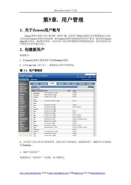
第5章.用户管理1. 关于Zenoss用户帐号Zenoss系统中的每个用户都有唯一的用户ID,这些用户ID通过权限以及告警规则进行分组,并以此成为zenoss系统安全的基础。
要在zenoss系统中创建或者管理用户帐号,就必须以Zenoss Admin帐号登录。
通过帐号管理,可以对用户进行事件视图和告警规则的定制,这些内容将在本手册的其它章节进行讨论。
2. 创建新用户新建帐号:1. 从Zenoss仪表板左侧的菜单中选择Settings(设置)。
2. 点击Users Tab(用户页),系统将显示用户管理界面。
图 5.1. 用户管理页3. 点击用户文件文件夹中的表菜单,将显示用户管理选项,包括添加用户、删除用户以及添加至Zenpacks。
.4. 选择“添加用户”系统将显示“添加用户”对话框,如下图所示:图 5.2. 添加用户对话框5. 输入用户名.6. 输入该用户帐号的一个电子邮件地址。
该电子邮件帐号将是未来接收系统告警的邮件帐号。
7. 点击OK按钮,新建的用户帐号将出现在用户列表中。
至此,一个新的用户帐号创建完毕。
管理员还可以继续编辑用户帐号以设置用户帐号口令以及其它更详细的信息,具体操作详见本用户手册的编辑用户帐号部分。
3. 编辑用户帐户1. 从Zenoss仪表板左侧的菜单中选择Settings(设置)。
2. 点击Users Tab(用户页),系统将显示用户管理界面。
3.点击需要编辑的帐号的用户名,系统将显示单一用户管理界面,如下图所示。
图 5.3. 单一用户管理页面4. 修改用户详细信息,点击Save(保存)按钮后保存退出。
.3.1. 设定用户密码从单一用户管理界面中,可以为用户指定口令。
在第一个文本框中输入用户口令,在第二个文本框中再次输入口令进行确认。
3.2. 编辑用户联系信息在单一用户管理界面中,管理员可以重新输入或者编辑用户的电子邮件地址或者寻呼机号码。
3.3. 向用户分派角色和权限在单一用户管理界面中,管理员可以为用户指定具体的角色。
ThinkServer TS140 用户手册 V1.2
IT用户帐号管理系统指导手册(中英文版)
IT用户帐号管理系统指导手册(中英文版)Ref: 3.1.DIT System GuidelineIT用户邮管理系统指导手册(IT User Account Management System Guideline) Rev Revision Details Author Effective Date 1.0 Initial release Ada Wong Dec 8, 2010 1.1 Updated Ada Wong Feb 16, 2011Main Contents1. 建立用户帐号(Create User Account)2. 编辑用户帐号信息(Modify User Account Information3. 删除用户帐号(Delete User Account)4. 邮件组(Email Grouping)5. 其它邮件授权(Other Email Authority)IT System GuidelineContents1. 建立用户帐号(Create UserAccount) (1)1.1 邮件(Email)................................................................. (1)1.1.1 邮件地址本显示名规则(Email Address Book Display Name Convention) .. 11.1.2 职员信息(StaffInformation) ........................................................... .. (2)1.1.3 邮件组(EmailGrouping) .............................................................. .. (2)1.1.4 Out of OfficeCalendar .................................................. 错误~未定义书签。
社科项目管理系统使用手册

社科项目管理系统使用手册(普通用户版)2020年3月目录一、用户登录 (3)1、用户登录 (3)2、用户注册 (4)二、普通用户操作说明 (7)1、首页 (7)2、项目申报 (7)(1)发起申报 (7)(2)选择申报项目类型 (9)(3)填写申报表 (9)(4)提交申报表 (11)(5)查看已申报项目状态 (12)3、待办任务 (14)(1)进度汇报 (15)(2)中期评估申请 (16)(3)结题申请 (16)(4)提交课题成果 (17)4、已办任务 (18)一、用户登录1、用户登录注意:(1)如果已经在社科联门户网站、“社科学术数据服务平台”的社科评奖系统、创新团队管理系统、社科项目管理系统、社科组织管理系统等系统注册过账号,使用已注册账号、密码登录即可;(2)如果没有注册过,需要先进行注册,具体操作参见“用户注册”章节。
社科项目管理系统的入口,在云南省社科联门户网站首页的“社科学术数据服务平台”中,点击“社科项目管理系统”:出现登录页面后,输入正确的账号、密码,点击登录即可:2、用户注册注意:以下情况不需要再进行注册:如果已经在社科联门户网站、“社科学术数据服务平台”的社科评奖系统、创新团队管理系统、社科项目管理系统、社科组织管理系统等系统注册过账号,使用已注册账号、密码登录即可。
如果之前没有注册过账号,需要先进行注册。
点击云南省社科联门户网站首页右上角的“用户登录”:出现如下登录界面:如果没有注册过,点击“申请注册”,在下面的界面中填写信息:填写说明:姓名、手机、身份证号、Email请务必填写正确。
填写完所有信息后,请点击“获取验证码”,获取到手机短信验证码,并填写在“验证码:”之后,再点击“注册”。
二、普通用户操作说明1、首页普通用户登录成功后,进入普通用户首页,可以进行信息查看,包括待办任务、通知公告、申报指南:对于已经申报的项目,如果有需要您处理的任务(如进度汇报、提交课题成果等),会出现在待办任务中,您可以点击待办任务中的项目名称进行处理。
Veritas 用户手册说明书

Veritas User Guide Quick Reference GuideTHANK YOU FOR VOTING TEXECOM THANK YOU FOR VOTING TEXECOMUSER GUIDESecurity Control PanelsIssue 21 INS167Overview Premier Series User Guide 2 INS221 IntroductionUsers of the alarm system will be assigned a unique 4, 5 or 6 digit User code. User codes are used to arm and disarm the system. Some User codes can also access additional options such as, system tests and omitting zones.Keypads will be installed throughout the premises, usually one at each entry/exit door. The keypads are used to perform all of the system operations i.e. Arming, Disarming etc. Most User codes can be used at any keypad on the system. However, Local Users will only be able to use certain keypads on the system.The Emergency KeysIn case of emergency, the alarm system can provide three immediate emergency alarms by pressing and holding two specific keys for two seconds. !"The emergency keys can be enabled/disabled for each keypad on the system.The Panic alarm can be programmed for either audible or silent operation.The Panic alarm can be programmed for either instant or delayed operation. Emergency AlarmPress KeysPanic Alarm (PA)! & " Fire# & $ Medical% & &The Quick Arm Keys The ‘Quick Arm’ keys allow the system to be armed without having to enter a User code first. !"The ‘Quick Arm’ keys will only work if the keypad has been programmed to allowarming in this way.To FULL arm the system, press '.To PART arm the system, press !, ( or " followed by ).Keypad LockThe keys on the keypad can be locked to prevent unwanted access to the system. !"The Emergency keys will NOT operate with the keys locked.To Lock the keys, press * and + together.To Unlock the keys, press * and + together again.Premier Serie s User Guide Overview INS221 3LED IndicatorsFive LED indicators have been provided to indicate the status of the system. LEDStatus Meaning PowerOn AC mains is present on the control panelFlashing AC Mains is not present, the control panel is running on the standby battery ServiceOn The system requires attention, contact your installerOff The system does NOT require attention ReadyOn All zones are secure and the system is ready to be armedOff One or more zones are activeFlashing The system has zones (with the ‘Force Omit’ attribute) that are active Info.On The system is armed (can also be programmed for other indications)Off The system is unarmed (can also be programmed for other indications) OmitOn One or more zones are omitted Off No zones are omittedZone Faults During ArmingBefore attempting to arm the system, ensure that the premises are secure (all doors and windows closed etc.) and the Ready light is on.If an attempt is made to arm the system with any zones active (e.g. door ajar, open window, etc.) the internal sounders will bleep repeatedly (fault tone) and the display will show the zones that are active.The fault tone will stop and the exit tone will resume when all zones are secure. If it is necessary to leave a zone open then it must be omitted (see page 8 for details). !"If an active zone cannot be secured then it may be ‘in fault’, in this case contact the alarm company immediately. Arm Fail - Failing to Arm If the exit procedure is started and zones are still ‘Active’ at the end of the exit procedure, an Internal alarm will occur (internal sounders only) and the strobe light on the external sounder will flash. !"If this occurs the arm fail must be cleared and the zone in fault identified before the system can be armed (see page 6 for details on clearing an Arm Fail). The Ready LED To help prevent faults during arming a Ready light has been provided, see table above for details on how the Ready LED operates.Operating the Alarm System Premier Series User Guide 4 INS221 To FULL Arm the SystemThe system is FULL Armed when ALL zones are ON (not omitted). !"Your Installer may have programmed the system so that it can be set by just pressing', if this is the case then there is no need to enter the User code below.1. Ensure that the premises are secure (all doors and windows closed etc.) and the Ready light is on2. Enter a valid User code ,,,,3. Press * to armThe exit tone will sound4. Leave the premisesWhen the system has armed the exit tone will stopTo PART Arm the SystemThe system is PART Armed , when ONE OR MORE zones have been left OFF (omitted) i.e. the landing or a bedroom. !"The system is only Part Armed when zones are omitted using the ‘Part Arm’ procedure(omitting zones manually (see page 8 for details) is not classed as Part Arming).The bottom line of the display is programmable for each Part Arm.Your Installer may have programmed the system so that it can be Part Armed by just pressing !, ( or " followed by ), if this is the case then there is no need to enter the User code below.1. Ensure that the premises are secure (all windows and doors not being omitted are closed) and the Ready light is on2. Enter a valid User code ,,,,3. Press )4. Use keys ! - " to select the required Part Arm5. Press * to arm normally or press - to arm silentlyThe exit tone will sound (if silent arm has not been selected)6. Leave the protected areaWhen the system has armed, the exit tone (if sounding) will stopPremier Serie s User Guide Operating the Alarm System INS221 5 To ARM Individual AreasIf the system has been split up into separate areas of protection i.e. Area 1 = House, Area 2 = Garage, Area 3 = Shed etc. These areas can be individually selected for FULL or PART arming as required. !"Areas are selected by using keys ! - . (the / key can also be used toselect an area followed by ' or +).Only areas that exist on the system can be selected. (A ‘Star’ means the area can be selected and a ‘Dot’ means the area cannot be selected).Pressing 0 will select/deselect all areas, pressing ' will toggle between the first 8 areas and the second 8 areas (where applicable).1. Ensure that the premises are secure (all windows and doors not being omitted are closed) and the Ready light is on2. Enter a valid User code ,,,,3. Press '4. Use keys ! - . to select the required areas5. Press * or - to FULL arm the areasOr5. Press )!, ( or " followed by * or - to PART arm the areas The exit tone will sound (if silent arm has not been selected)6. Leave the premisesWhen the system has armed, the exit tone (if sounding) will stop To DISARM the SystemThe entry time is divided into two sections, the Entry time and the 2nd Entry time. If the Entry time expires, an Internal alarm will occur and the 2nd Entry time will start. If the 2nd Entry time expires, an Intruder alarm will occur (all internal and external sounders). !"It is perfectly normal for the 2nd Entry time to be programmed as zero, in whichcase, an Intruder alarm will occur as soon as the Entry time expires.1. Enter the premises via the designated entry pointThe entry tone will start2. Enter a valid User code ,,,,The entry tone will stopOperating the Alarm System Premier Series User Guide 6 INS221 To DISARM the System When Not in Entry1. Enter a valid User code ,,,,2. Press * To CANCEL the Exit ModeOnce the exit mode has been started you should leave the premises immediately, however, if for some reason you decide not to leave, the exit mode must be cancelled.1. Enter a valid User code ,,,,2. Press *The exit tone will stop. To CLEAR an Arm FailWhen the system tries to arm with zones active (open), the internal sounders will sound and the external strobe will be flashing to indicate a problem. For details on preventing an Arm Fail condition, please refer to page 3. !"If you were not present when the Arm Fail occurred or you do not clear the ArmFail, the internal sounders will continue to sound and the external strobe will continue to flash.1. Enter a valid User code ,,,,The internal and external sounders will stop, the external strobe will continue to flash and the number of the zone that caused the Arm Fail will be displayed.2. Enter a valid User code ,,,, and press 12 To SILENCE an AlarmWhen an alarm occurs on the system, the internal and external sounders will normally sound for a pre-programmed time (normally 15 minutes). !"If you were not present when the alarm activated, the internal and externalsounders may have already stopped but the external strobe will still be flashing. When alarm information is being displayed, pressing the SCROLL key will slow down the display and also allow manual scrolling through the events.1. Enter a valid User code ,,,,The internal and external sounders will stop and the number of the zone that caused the alarm will be displayed.The alarm now needs to be reset.Premier Serie s User Guide Operating the Alarm System INS221 7 To RESET After an AlarmUSER ResetOnce the alarm has been silenced (see page 6 for details), the system will need to be reset. !"If the system has been programmed, to be reset by an Engineer, pressing 1 willnot return the display to normal, if this is the case see ENGINEER Reset for details. The system may have been programmed to be reset by Anti-code, if this is the case, see ANTI-CODE Reset for details.1. Enter a valid User code ,,,,2. Press 1The external strobe will stop, the system will chime and the display will return to normal. ENGINEER ResetIf the system has been programmed to be reset by an Engineer following an alarm activation, you will still be able to silence the alarm by entering a valid User code (see page 6 for details). !"The system cannot be armed again until the alarm has been reset.1. Contact the telephone number on the display (if programmed) or the telephone number on the last page of this User GuideANTI-CODE ResetIf the system has been programmed to be reset using an Anti-Code following an alarm activation, you will still be able to silence the alarm by entering a valid User code (see page 6 for details).!"The system cannot be armed again until the alarm has been reset.1. Enter a valid User code ,,,,2. Press 1The display will show a random code number i.e. 4281.3. Contact the telephone number on the display (if programmed) or the telephone number on the last page of this User Guide and quote the random code number You will be given a 4-digit Anti-Code i.e. 5624.4. Enter the Anti-code that has been given to you ,,,,5. Press *If the Anti-code is correct, the keypad will bleep to indicate that the system has been reset and the display will return to normal.Operating the Alarm System Premier Series User Guide 8 INS221 To OMIT ZonesIt is possible to exclude (omit) individual zones when arming i.e. if a zone is ‘in fault’. Users with access to this function can only omit zones that have been programmed as ‘Omittable’. !"If the zone can be omitted, there will be a ‘Star’ to the right of the zone number.Only zones that have the ‘Omit’ attribute assigned to them can be omitted.A ‘Star’ will appear to the left of the zone number to indicate that the zone has been selected for omitting.All omitted zones will be automatically reinstated the next time the system is disarmed, unless programmed otherwise.To re-instate zones manually, simply follow the instructions again. However, when the 3 key is pressed on this occasion, the zones will be re-instated.1. Enter a valid User code ,,,, and press 32. Enter the zone number ,,,3. Press 3 to omit the selected zoneRepeat for other zones if required.4. Press 4 when finishedContinue to arm the system as normal. The Turn CHIME On and OffThe system can be set up so that activating (opening) certain zones will cause the internal sounders to chime. This would normally be used on a front door, exit button etc. !"Zones will only cause the internal sounders to chime if they are selected for chime (see page Master User Guide for details on selecting which zones chime). Once a zone has been selected for chime, the Chime facility can be manually turned on and off as required.!"The system can also be programmed to automatically turn chime on and off under certain conditions i.e. certain times of the day, door left open etc.If no zones have been programmed for Chime, then turning Chime on and off will have no effect.To turn CHIME OnTo turn CHIME Off 1. Press -1. Press - The Chime tone will sound.The Error tone will sound.Premier Serie s User Guide Operating the Alarm System INS221 9 To CHANGE Your User CodeUsers with access to this option can change their own User codes. User codes are unique to each user and can be 4, 5 or 6 digits long.!"Only the User code that is entered to access the change code menu will be changed. Before changing your code, it is vital that you memorise or write down the new code you are about to program. Failure to remember your code will require an engineer visit to re-program a new code for you. This may incur a call-out charge.1. Enter the User code that requires changing ,,,,2. Press 43. Press *4. Press (5. Press *6. Enter a new 4, 5 or 6-digit User code ,,,,7. Press * to accept the new code8. Press 1 to exit the menuThe display will return to normal.Quick Reference Guide Premier Series User Guide10 INS221 OperationDescription Action To Full Arm the SystemEnter a valid User code ,,,, Press Yes (or press Chime to arm silently) * or - To Part Arm the System Enter a valid User code ,,,, Press Part ) Select Required Part Arm !, ( or " Press Yes (or press Chime to arm silently) * or - To Arm Individual Areas Enter a valid User code ,,,, Press Area ' Select Required Area using keys 1 - 8 ! - . Press Yes (or press Chime to arm silently) * or - To Disarm the System Enter a valid User code ,,,, Press Yes (if the entry mode was not started) *To Cancel the Exit Mode Enter a valid User code ,,,, Press Yes * To Clear an Arm Fail Enter a valid User code ,,,, Press Reset 1 To Silence an Alarm Enter a valid User code ,,,, To Reset After an Alarm Enter a valid User code ,,,, Press Reset 1 To Engineer Reset Contact Your Installation Company_____________ To Anti-code Reset Enter a valid User code ,,,, Press Reset 1 Contact Your Alarm Receiving Centre_____________ Quote 4-digit code shown on display !"#$%&'((((' Enter 4-digit code given by Receiving Centre ,,,, Press Yes *To Omit Zones Enter a valid User code ,,,, Press Omit 3 Enter Zone Number(s) ,,,… Press Menu when finished 3 Press Yes to Arm * Turn Chime On/Off Press Chime Once to Turn ON - Press Chime Again to Turn OFF - To Change User Code Enter a valid User code ,,,, Press Menu followed by Yes 4* Press 2 followed by Yes (* Enter a new 4, 5 or 6 digit User code ,,,, Press Yes to accept * Press Reset to return to the normal display 1Premier Series User Guide Installation DetailsINS221 11AreasNo. DescriptionExit TimeEntry Time 1Entry Time 2Bell DelayBell DurationAbort TimeSec. Sec. Sec. Min. Min. Sec. Sec. Sec. Sec. Min. Min. Sec. Sec. Sec. Sec. Min. Min. Sec.Sec.Sec.Sec.Min.Min.Sec.KeypadsEmergency Keys No. LocationArea Quick Arm PA Fire MedUser CodesUser Name Type Default New Code Area Time Lock 01 Master 5678N/AN/AN/AN/AN/AZonesPart ArmsNo. DescriptionType Area Omit 12 3Installation Company DetailsInstallation Engineer:Installation Company:Address:Telephone Number:Installation Date:Service RecordDate Serviced Comments EngineerEmergency Telephone NumbersFor 24 Hour Call Out For Anti-Code ResetControl PanelDetailsModel Premier 24 ❏Premier 48 ❏Premier 88 ❏Premier 168 ❏ Premier 640 ❏Location© TEXECOM LTD. 2000 - 2005INS221-2。
软件使用手册范文(3篇)

第1篇第一章:概述1.1 软件简介XX办公自动化系统是一款集成了文档管理、邮件处理、日程安排、会议管理、项目管理等功能于一体的综合性办公软件。
它旨在提高工作效率,简化办公流程,为用户提供便捷、高效的办公体验。
1.2 系统功能1. 文档管理:支持文档的上传、下载、编辑、分享等功能。
2. 邮件处理:提供邮件收发、邮件分类、邮件搜索等功能。
3. 日程安排:支持日程的添加、修改、删除、提醒等功能。
4. 会议管理:支持会议的创建、修改、删除、参会人员管理等功能。
5. 项目管理:支持项目的创建、分配、进度跟踪、任务管理等功能。
1.3 系统环境1. 操作系统:Windows 7/8/10、Mac OS X 10.10及以上版本2. 处理器:Intel Core i3及以上3. 内存:4GB及以上4. 硬盘:100GB及以上5. 网络环境:宽带网络第二章:安装与启动2.1 安装步骤1. 下载软件安装包:请访问官方网站或授权渠道下载最新版本的XX办公自动化系统安装包。
2. 双击安装包,进入安装向导。
3. 阅读许可协议,勾选“我同意”后点击“下一步”。
4. 选择安装路径,点击“下一步”。
5. 等待安装完成,点击“完成”。
2.2 启动软件1. 在桌面找到XX办公自动化系统的快捷方式,双击打开。
2. 输入用户名和密码,点击“登录”。
第三章:功能模块使用指南3.1 文档管理1. 上传文档:点击“文档”菜单,选择“上传文档”,选择需要上传的文件,点击“上传”。
2. 下载文档:点击文档列表中的文件名,点击“下载”。
3. 编辑文档:双击文档列表中的文件名,打开文档进行编辑。
4. 分享文档:选中文档,点击“分享”,输入分享对象和权限,点击“分享”。
3.2 邮件处理1. 收发邮件:点击“邮件”菜单,进入邮件收发界面。
2. 邮件分类:点击“邮件”菜单,选择“邮件分类”,创建或编辑分类。
3. 邮件搜索:在邮件收发界面,输入搜索关键词,点击“搜索”。
CSSCNeoShineOffice3.0UserGuide-Chinese
3.3 文件操作及格式 ......................................................................................................... 38 3.3.1 新建文件..................................................................................................................... 38 3.3.2 打开文件..................................................................................................................... 40 3.3.3 保存文件..................................................................................................................... 42 3.3.4 发送文件..................................................................................................................... 45 3.3.5 关闭文件..................................................................................................................... 46 3.3.6 查看文件的属性 ......................................................................................................... 46 3.3.7 文件兼容性 ................................................................................................................. 47
软件用户操作手册编写模板
软件用户操作手册1.引言1.1编写目的【阐明编写手册的目的,指明读者对象。
】1.2项目背景【说明项目来源、委托单位、开发单位及主管部门。
】1.3定义【列出手册中使用的专门术语的定义和缩写词的原意。
】1.4参考资料【列出有关资料的作者、标题、编号、发表日期、出版单位或资料来源,可包括:a.项目的计划任务书、合同或批文.b.项目开发计划.c.需求规格说明书;d.概要设计说明书;e.详细设计说明书;f.测试计划;g.手册中引用的其他资料、采用的软件工程标准或软件工程规范。
】2.软件概述2.1目标2.2功能2.3性能a.数据精确度【包括输入、输出及处理数据的精度。
】b.时间特性【如响应时间、处理时间、数据传输时间等。
】c.灵活性【在操作方式、运行环境需做某些变更时软件的适应能力。
】3.运行环境3.1硬件【列出软件系统运行时所需的硬件最小配置,如a.计算机型号、主存容量.b.外存储器、媒体、记录格式、设备型号及数量.c.输入、输出设备;d.数据传输设备及数据转换设备的型号及数量。
】3.2支持软件【如:a.操作系统名称及版本号.b.语言编译系统或汇编系统的名称及版本号;c.数据库管理系统的名称及版本号;d.其他必要的支持软件。
】4.使用说明4.1安装和初始化【给出程序的存储形式、操作命令、反馈信息及其含意、表明安装完成的测试实例以及安装所需的软件工具等。
】4.2输入【给出输入数据或参数的要求。
】4.2.1数据背景【说明数据来源、存储媒体、出现频度、限制和质量管理等。
】4.2.2数据格式【如.a.长度.b.格式基准;c.标号;d.顺序;e.分隔符;f.词汇表;g.省略和重复;h.控制。
】4.2.3输入举例4.3输出【给出每项输出数据的说明。
】4.3.1数据背景【说明输出数据的去向、使用频度、存放媒体及质量管理等。
】4.3.2数据格式【详细阐明每一输出数据的格式,如:首部、主体和尾部的具体形式。
】4.3.3举例4.4出错和恢复【给出:a.出错信息及其含意.b.用户应采取的措施,如修改、恢复、再启动。
用户手册(英文)模板 (user manual template)
U SER’SM ANUALProject or System NameU.S. Department of Housing and Urban Development Month, YearRevision Sheet Revision SheetI have carefully assessed the User’s Manual for the (System Name). This document has been completed in accordance with the requirements of the HUD System Development Methodology. MANAGEMENT CERTIFICATION - Please check the appropriate statement.______ The document is accepted.______ The document is accepted pending the changes noted.______ The document is not accepted.We fully accept the changes as needed improvements and authorize initiation of work to proceed. Based on our authority and judgment, the continued operation of this system is authorized._______________________________ _____________________ NAME DATEProject Leader_______________________________ _____________________ NAME DATEOperations Division Director_______________________________ _____________________ NAME DATEProgram Area/Sponsor Representative_______________________________ _____________________ NAME DATEProgram Area/Sponsor DirectorUSER'S MANUALTABLE OF CONTENTSPage #1.0 GENERAL INFORMATION .......................................................................................................... 1-11.1 System Overview ................................................................................................................... 1-11.2 Project References .................................................................................................................. 1-21.3 Authorized Use Permission .................................................................................................... 1-21.4 Points of Contact .................................................................................................................... 1-21.4.1 Information .............................................................................................................................1-21.4.2 Coordination ...........................................................................................................................1-21.4.3 Help Desk ...............................................................................................................................1-21.5 Organization of the Manual ................................................................................................... 1-21.6 Acronyms and Abbreviations ................................................................................................. 1-22.0 SYSTEM SUMMARY .................................................................................................................... 2-12.1 System Configuration ............................................................................................................. 2-12.2 Data Flows.............................................................................................................................. 2-12.3 User Access Levels ................................................................................................................ 2-12.4 Contingencies and Alternate Modes of Operation ................................................................. 2-13.0 GETTING STARTED ..................................................................................................................... 3-13.1 Logging On ............................................................................................................................. 3-13.2 System Menu .......................................................................................................................... 3-13.2.x [System Function Name] .........................................................................................................3-13.3 Changing User ID and Password ............................................................................................ 3-13.4 Exit System ............................................................................................................................ 3-14.0 USING THE SYSTEM (ONLINE) .................................................................................................. 4-14.x [System Function Name] ........................................................................................................ 4-14.x.y [System Sub-Function Name] .................................................................................................4-14.2 Special Instructions for Error Correction ............................................................................... 4-14.3 Caveats and Exceptions .......................................................................................................... 4-15.0 USING THE SYSTEM (BATCH) ................................................................................................... 5-15.x [System Function Name] ........................................................................................................ 5-15.x.y [System Sub-Function Name] .................................................................................................5-15.2 Special Instructions for Error Correction ............................................................................... 5-15.3 Caveats and Exceptions .......................................................................................................... 5-15.4 Input Procedures and Expected Output .................................................................................. 5-16.0 QUERYING ..................................................................................................................................... 6-16.1 Query Capabilities .................................................................................................................. 6-16.2 Query Procedures ................................................................................................................... 6-17.0 REPORTING ................................................................................................................................... 7-17.1 Report Capabilities ................................................................................................................. 7-17.2 Report Procedures .................................................................................................................. 7-11.0 GENERAL INFORMATIONNOTE TO AUTHOR:highlighted, italicized text throughout this template is provided solely as background information to assist you in creating this document. Please delete all such text, as well as the instructions in each section, prior to submitting this document. ONLY YOUR PROJECT-SPECIFIC INFORMATION SHOULD APPEAR IN THE FINAL VERSION OF THIS DOCUMENT.The User’s Manual provides the information necessary for the user to effectively use the automated information system.1.0 GENERAL INFORMATION1.1 System OverviewExplain in general terms the system and the purpose for which it is intended. The description shall include:•Major functions performed by the system•Describe the architecture of the system in non-technical terms, (e.g., client/server, Web-based, etc.)•User access mode, (e.g., graphical user interface)•Responsible organization•System name or title•System code•System category:-Major application:performs clearly defined functions for which there is a readily identifiable security consideration and need-General support system:provides general ADP or network support for a variety of users and applications•Operational status:-Operational-Under development-Undergoing a major modification•General description•System environment or special conditions1.2 Project ReferencesProvide a list of the references that were used in preparation of this document in order of importance to the end user.1.3 Authorized Use PermissionProvide a warning regarding unauthorized usage of the system and making unauthorized copies of data, software, reports, and documents, if applicable. If waiver use or copy permissions need to be obtained, describe the process.1.4 Points of Contact1.4.1 InformationProvide a list of the points of organizational contact (POCs) that may be needed by the document user for informational and troubleshooting purposes. Include type of contact, contact name, department, telephone number, and e-mail address (if applicable). Points of contact may include, but are not limited to, help desk POC, development/maintenance POC, and operations POC.1.4.2 CoordinationProvide a list of organizations that require coordination between the project and its specific support function (e.g., installation coordination, security, etc.). Include a schedule for coordination activities. 1.4.3 Help DeskProvide help desk information including responsible personnel phone numbers for emergency assistance.1.5 Organization of the ManualProvide a list of the major sections of the User’s Manual (1.0, 2.0, 3.0, etc.) and a brief description of what is contained in each section.1.6 Acronyms and AbbreviationsProvide a list of the acronyms and abbreviations used in this document and the meaning of each.2.0 SYSTEM SUMMARY2.0 SYSTEM SUMMARYThis section provides a general overview of the system written in non-technical terminology. The summary should outline the uses of the system in supporting the activities of the user and staff.2.1 System ConfigurationBriefly describe and depict graphically the equipment, communications, and networks used by the system. Include the type of computer input and output devices.2.2 Data FlowsBriefly describe or depict graphically, the overall flow of data in the system. Include a user-oriented description of the method used to store and maintain data.2.3 User Access LevelsDescribe the different users and/or user groups and the restrictions placed on system accessibility or use for each.2.4 Contingencies and Alternate Modes of OperationOn a high level, explain the continuity of operations in the event of emergency, disaster, or accident. Explain what the effect of degraded performance will have on the user.3.0 GETTING STARTED3.0 GETTING STARTEDThis section provides a general walkthrough of the system from initiation through exit. The logical arrangement of the information shall enable the functional personnel to understand the sequence and flow of the system. Use screen prints to depict examples of text under each heading.3.1 Logging OnDescribe the procedures necessary to access the system, including how to get a user ID and log on. If applicable, identify job request forms or control statements and the input, frequency, reason, origin, and medium for each type of output.3.2 System MenuThis section describes in general terms the system menu first encountered by the user, as well as the navigation paths to functions noted on the screen. Each system function should be under a separate section header, 3.2.1 - 3.2.x.3.2.x [System Function Name]Provide a system function name and identifier here for reference in the remainder of the subsection. Describe the function and pathway of the menu item. Provide an average response time to use the function.3.3 Changing User ID and PasswordDescribe how the user changes a user ID. Describe the actions a user must take to change a password.3.4 Exit SystemDescribe the actions necessary to properly exit the system.4.0 USING THE SYSTEM (ONLINE)This section provides a detailed description of the online system from initiation through exit, explaining in detail the characteristics of the required input and system-produced output. THIS SECTION IS ONLY TO BE USED FOR ONLINE SYSTEMS. IF YOU ARE DEVELOPING A BATCH SYSTEM, USE SECTION 5.0 AND OMIT THIS SECTION ENTIRELY.4.0 USING THE SYSTEM (ONLINE)This section provides a detailed description of system functions. Each function should be under a separate section header, 4.1 - 4.x, and should correspond sequentially to the system functions (menu items) listed in subsections 3.2.1 - 3.2.x.4.x [System Function Name]Provide a system function name and identifier here for reference in the remainder of the subsection. Describe the function in detail and depict graphically. Include screen captures and descriptive narrative.4.x.y [System Sub-Function Name]This subsection provides a detailed description of system sub-functions. Each sub-function should be under a separate section header, 4.1.1. - 4.x.y . Where applicable, for each sub-function referenced within a section in 4.x, describe in detail and depict graphically the sub-function name(s) referenced. Include screen captures and descriptive narrative.The numbering of the following two sections will depend on how many system functions there are from 4.1 through 4.x. They are numbered here as 4.2 and 4.3 only for the sake of convenience. For example, if system functions run from sections 4.1 through 4.17, then the following two sections would be numbered 4.18 and 4.19.4.2 Special Instructions for Error CorrectionDescribe all recovery and error correction procedures, including error conditions that may be generated and corrective actions that may need to be taken.4.3 Caveats and ExceptionsIf there are special actions the user must take to insure that data is properly saved or that some other function executes properly, describe those actions here. Include screen captures and descriptive narratives, if applicable.5.0 USING THE SYSTEM (BATCH)This section provides a detailed description of the batch system from initiation through exit, explaining in detail the characteristics of the required input and system-produced output. THIS SECTION IS ONLY TO BE USED FOR BATCH SYSTEMS. IF YOU ARE DEVELOPING AN ONLINE SYSTEM, USE SECTION 4.0 AND OMIT THIS SECTION ENTIRELY.5.0 USING THE SYSTEM (BATCH)This section provides a detailed description of system functions. Each function should be under a separate section header, 5.1 - 5.x, and should correspond sequentially to the system functions (menu items) listed in subsections 3.2.1 - 3.2.x.5.x [System Function Name]Provide a system function name and identifier here for reference in the remainder of the subsection. Describe the function in detail and depict graphically. Include screen captures and descriptive narrative.5.x.y [System Sub-Function Name]This subsection provides a detailed description of system sub-functions. Each sub-function should be under a separate section header, 5.1.1 - 5.x.y. Where applicable, for each sub-function referenced within a section in 5.x, describe in detail and depict graphically the sub-function name(s) referenced. Include screen captures and descriptive narrative.The numbering of the following three sections will depend on how many system functions there are from 5.1 through 5.x. They are numbered here as 5.2, 5.3, and 5.4 only for the sake of convenience. For example, if system functions run from sections 5.1 through 5.17, then the following three sections would be numbered 5.18, 5.19 and 5.20.5.2 Special Instructions for Error CorrectionDescribe all recovery and error correction procedures, including error conditions that may be generated and corrective actions that may need to be taken.5.3 Caveats and ExceptionsIf there are special actions the user must take to insure that data is properly saved or that some other function executes properly, describe those actions here. Include screen captures and descriptive narratives, if applicable.5.4 Input Procedures and Expected OutputPrepare a detailed series of instructions (in non technical terms) describing the procedures the user will need to follow to use the system. The following information should be included in these instructions: •Detailed procedures to initiate system operation, including identification of job request forms or control statements and the input’s frequency, reason, origin, and medium for each type of output•Illustrations of input formats•Descriptions of input preparation rules•Descriptions of output procedures identifying output formats and specifying the output’s purpose, frequency, options, media, and location•Identification of all codes and abbreviations used in the system’s output6.0 QUERYING6.0 QUERYINGThis section describes the query and retrieval capabilities of the system. The instructions necessary for recognition, preparation, and processing of a query applicable to a database shall be explained in detail. Use screen prints to depict examples of text under each heading.6.1 Query CapabilitiesDescribe or illustrate the pre-programmed and ad hoc query capabilities provided by the system. Include query name or code the user would invoke to execute the query. Include query parameters if applicable.6.2 Query ProceduresDevelop detailed descriptions of the procedures necessary for file query including the parameters of the query and the sequenced control instructions to extract query requests from the database.7.0 REPORTING7.0 Reporting 7.0 REPORTINGThis section describes and depicts all standard reports that can be generated by the system or internal to the user. Use screen prints as needed to depict examples of text under each heading.7.1 Report CapabilitiesDescribe all reports available to the end user. Include report format and the meaning of each field shown on the report. If user is creating ad hoc reports with special formats, please describe here. A separate subsection may be used for each report.7.2 Report ProceduresProvide instructions for executing and printing the different reports available. Include descriptions of output procedures identifying output formats and specifying the output’s purpose, frequency, options, media, and location.User’s Manual Page 7-1。
H3C WX5510E无线控制器 安装指导-AW100-整本手册
环境保护
本产品符合关于环境保护方面的设计要求,产品的存放、使用和弃置应遵照相关国家法律、法规要 求进行。
前言
H3C WX5510E 无线控制器安装指导介绍了 WX5510E 安装前的准备、安装、初次上电启动、故障 处理、接口模块选配参考和软件维护等内容。 前言部分包含如下内容: • 读者对象 • 本书约定 • 资料获取方式 • 技术支持 • 资料意见反馈
• 在断开光纤连接器之前,在命令行接口视图下使用 shutdown 命令以确保关闭光源。 • 断开光纤后使用光纤帽保护光纤连接器,避免因灰尘过多而产生静电,导致激光器损坏或影响
其性能指标。
1.2 安装场所要求
设备必须在室内使用,为保证设备正常工作并延长使用寿命,安装场所应该满足下列要求。
1.2.1 温度/湿度要求
称,由各自权利人拥有。
由于产品版本升级或其他原因,本手册内容有可能变更。H3C 保留在没有任何通知或者提示的情况 下对本手册的内容进行修改的权利。本手册仅作为使用指导,H3C 尽全力在本手册中提供准确的信 息,但是 H3C 并不确保手册内容完全没有错误,本手册中的所有陈述、信息和建议也不构成任何
明示或暗示的担保。
H3C WX5510E 无线控制器 安装指导
杭州华三通信技术有限公司 资料版本:AW100-20140102
Copyright © 2014 杭州华三通信技术有限公司及其许可者 版权所有,保留一切权利。 未经本公司书面许可,任何单位和个人不得擅自摘抄、复制本书内容的部分或全部,并不得以任何 形式传播。
表1-2 粒/m3
单位
含量 ≤3×10⁴(3天内桌面无可见灰尘)
注:灰尘粒子直径≥5μm
1-2
除灰尘外,设备机房对空气中所含的盐、酸、硫化物也有严格的要求。这些有害气体会加速金属的 腐蚀和某些部件的老化过程。机房内应防止有害气体如 SO2、H2S、NH3、Cl2 等的侵入,其具体限 制值参见下表。