工程有限元分析英文课件:A Comment on Convergence for 3D
工程有限元分析英文课件:Formulation of Isoparametric

0 0
1 j (1 i )
0 0
e
y ati j
v
(3.57)
x
v
1 4
Jij
1
0 0
1 j 1 i
0 0
(1 j ) 1 i
0 0
(1 j ) (1 i )
0 0
1 j (1 i
)
e
y ati j
with
T e
u1
v1
u2
v2
u3
v3
u4
v4
- the vector listing the element nodal point displacements8
1
B 2
B i
B
n
(3.42)
N
i
x
[B]i 0
Ni y
0
Ni y
Ni x
x
J
1
y
x y
J
x y
3
Formulation of Isoparametric Finite Element Matrices
Inverse of Jacobian Operator at a Specific Point
Formulation of Isoparametric Finite Element Matrices 3.4 Formulation of Isoparametric Finite Element Matrices
for Plane Elasticity (平面弹性问题)
The interpolation of the element coordinates and element displacements using the same interpolation functions, which are defined in a natural coordinate system, is the basis of the isoparametric finite element formulation.
有限元分析及应用课件

设置材料属性、单元类型等参数。
求解过程
刚度矩阵组装
根据每个小单元的刚度,组装成全局的刚度矩阵。
载荷向量构建
根据每个节点的外载荷,构建全局的载荷向量。
求解线性方程组
使用求解器(如雅可比法、高斯消元法等)求解线性方程组,得到节点的位移。
后处理
01
结果输出
将计算结果以图形、表格等形式输 出,便于观察和分析。
有限元分析广泛应用于工程领域,如结构力学、流体动力学、电磁场等领域,用于预测和优化结构的 性能。
有限元分析的基本原理
离散化
将连续的求解域离散化为有限 个小的单元,每个单元具有特
定的形状和属性。
数学建模
根据物理问题的性质,建立每 个单元的数学模型,包括节点 力和位移的关系、能量平衡等。
求解方程
通过建立和求解线性或非线性 方程组,得到每个节点的位移 和应力分布。
PART 05
有限元分析的工程应用实 例
桥梁结构分析
总结词
桥梁结构分析是有限元分析的重要应用之一,通过模拟桥梁在不同载荷下的响应,评估 其安全性和稳定性。
详细描述
桥梁结构分析主要关注桥梁在不同载荷(如车辆、风、地震等)下的应力、应变和位移 分布。通过有限元模型,工程师可以预测桥梁在不同工况下的行为,从而优化设计或进
刚性问题
刚性问题是有限元分析中的一种 特殊问题,主要表现在模型中某 些部分刚度过大,导致分析结果 失真
刚性问题通常出现在大变形或冲 击等动态分析中,由于模型中某 些部分刚度过高,导致变形量被 忽略或被放大。这可能导致分析 结果与实际情况严重不符。
解决方案:为避免刚性问题,可 以采用多种方法进行优化,如采 用更合适的材料模型、调整模型 中的参数设置、采用更精细的网 格等。同时,可以采用多种方法 对分析结果进行验证和校核,以 确保其准确性。
有限元分析中英文对照资料知识讲解

有限元分析中英文对照资料The finite element analysisFinite element method, the solving area is regarded as made up of many small in the node connected unit (a domain), the model gives the fundamental equation of sharding (sub-domain) approximation solution, due to the unit (a domain) can be divided into various shapes and sizes of different size, so it can well adapt to the complex geometry, complex material properties and complicated boundary conditions Finite element model: is it real system idealized mathematical abstractions. Is composed of some simple shapes of unit, unit connection through the node, and under a certain load.Finite element analysis: is the use of mathematical approximation method for real physical systems (geometry and loading conditions were simulated. And by using simple and interacting elements, namely unit, can use a limited number of unknown variables to approaching infinite unknown quantity of the real system.Linear elastic finite element method is a ideal elastic body as the research object, considering the deformation based on small deformation assumption of. In this kindof problem, the stress and strain of the material is linear relationship, meet the generalized hooke's law; Stress and strain is linear, linear elastic problem boils down to solving linear equations, so only need less computation time. If the efficient method of solving algebraic equations can also help reduce the duration of finite element analysis.Linear elastic finite element generally includes linear elastic statics analysis and linear elastic dynamics analysis from two aspects. The difference between the nonlinear problem and linear elastic problems:1) nonlinear equation is nonlinear, and iteratively solving of general;2) the nonlinear problem can't use superposition principle;3) nonlinear problem is not there is always solution, sometimes even no solution. Finite element to solve the nonlinear problem can be divided into the following three categories:1) material nonlinear problems of stress and strain is nonlinear, but the stress and strain is very small, a linear relationship between strain and displacement at this time, this kind of problem belongs to the material nonlinear problems. Due to theoretically also cannot provide the constitutive relation can be accepted, so, general nonlinear relations between stress and strain of the material based on the test data, sometimes, to simulate the nonlinear material properties available mathematical model though these models always have their limitations. More important material nonlinear problems in engineering practice are: nonlinear elastic (including piecewise linear elastic, elastic-plastic and viscoplastic, creep, etc.2) geometric nonlinear geometric nonlinear problems are caused due to the nonlinear relationship between displacement. When the object the displacement is larger, the strain and displacement relationship is nonlinear relationship. Research on this kind of problemIs assumes that the material of stress and strain is linear relationship. It consists of a large displacement problem of large strain and large displacement little strain. Such as the structure of the elastic buckling problem belongs to the large displacement little strain, rubber parts forming process for large strain.3) nonlinear boundary problem in the processing, problems such as sealing, the impact of the role of contact and friction can not be ignored, belongs to the highly nonlinear contact boundary. At ordinary times some contact problems, such as gear, stamping forming, rolling, rubber shock absorber, interference fit assembly, etc., when a structure and another structure or external boundary contact usually want to consider nonlinear boundary conditions. The actual nonlinear may appear at the same time these two or three kinds of nonlinear problems.Finite element theoretical basisFinite element method is based on variational principle and the weighted residual method, and the basic solving thought is the computational domain is divided into a finite number of non-overlapping unit, within each cell, select some appropriate nodes as solving the interpolation function, the differential equation of the variables in the rewritten by the variable or its derivative selected interpolation node value and the function of linear expression, with the aid of variational principle or weighted residual method, the discrete solution of differential equation. Using different forms of weight function and interpolation function, constitute different finite element methods. 1. The weighted residual method and the weighted residual method of weighted residual method of weighted residual method: refers to the weighted function is zero using make allowance for approximate solution of the differential equation method is called the weighted residual method. Is a kind of directly from the solution of differential equation and boundary conditions, to seek the approximate solution of boundary value problems of mathematical methods. Weighted residual method is to solve the differential equation of the approximate solution of a kind of effective method. Hybrid method for the trial function selected is the most convenient, but under the condition of the same precision, the workload is the largest. For internal method and the boundary method basis function must be made in advance to meet certain conditions, the analysis of complex structures tend to have certain difficulty, but the trial function is established, the workload is small. No matter what method is used, when set up trial function should be paid attention to are the following:(1) trial function should be composed of a subset of the complete function set. Have been using the trial function has the power series and trigonometric series, spline functions, beisaier, chebyshev, Legendre polynomial, and so on.(2) the trial function should have until than to eliminate surplus weighted integral expression of the highest derivative low first order derivative continuity.(3) the trial function should be special solution with analytical solution of the problem or problems associated with it. If computing problems with symmetry, should make full use of it. Obviously, any independent complete set of functions can be used as weight function. According to the weight function of the different options fordifferent weighted allowance calculation method, mainly include: collocation method, subdomain method, least square method, moment method and galerkin method. The galerkin method has the highest accuracy.Principle of virtual work: balance equations and geometric equations of the equivalent integral form of "weak" virtual work principles include principle of virtual displacement and virtual stress principle, is the floorboard of the principle of virtual displacement and virtual stress theory. They can be considered with some control equation of equivalent integral "weak" form. Principle of virtual work: get form any balanced force system in any state of deformation coordinate condition on the virtual work is equal to zero, namely the system of virtual work force and internal force of the sum of virtual work is equal to zero. The virtual displacement principle is the equilibrium equation and force boundary conditions of the equivalent integral form of "weak"; Virtual stress principle is geometric equation and displacement boundary condition of the equivalent integral form of "weak". Mechanical meaning of the virtual displacement principle: if the force system is balanced, they on the virtual displacement and virtual strain by the sum of the work is zero. On the other hand, if the force system in the virtual displacement (strain) and virtual and is equal to zero for the work, they must balance equation. Virtual displacement principle formulated the system of force balance, therefore, necessary and sufficient conditions. In general, the virtual displacement principle can not only suitable for linear elastic problems, and can be used in the nonlinear elastic and elastic-plastic nonlinear problem.Virtual mechanical meaning of stress principle: if the displacement is coordinated, the virtual stress and virtual boundary constraint counterforce in which they are the sumof the work is zero. On the other hand, if the virtual force system in which they are and is zero for the work, they must be meet the coordination. Virtual stress in principle, therefore, necessary and sufficient condition for the expression of displacement coordination. Virtual stress principle can be applied to different linear elastic and nonlinear elastic mechanics problem. But it must be pointed out that both principle of virtual displacement and virtual stress principle, rely on their geometric equation and equilibrium equation is based on the theory of small deformation, they cannot be directly applied to mechanical problems based on large deformation theory. 3,,,,, the minimum total potential energy method of minimum total potential energy method, the minimum strain energy method of minimum total potential energy method, the potential energy function in the object on the external load will cause deformation, the deformation force during the work done in the form of elastic energy stored in the object, is the strain energy.The convergence of the finite element method, the convergence of the finite element method refers to when the grid gradually encryption, the finite element solution sequence converges to the exact solution; Or when the cell size is fixed, the more freedom degree each unit, the finite element solutions tend to be more precise solution. Convergence condition of the convergence condition of the finite element finite element convergence condition of the convergence condition of the finite element finite element includes the following four aspects: 1) within the unit, the displacement function must be continuous. Polynomial is single-valued continuous function, sochoose polynomial as displacement function, to ensure continuity within the unit. 2) within the unit, the displacement function must include often strain. Total can be broken down into each unit of the state of strain does not depend on different locations within the cell strain and strain is decided by the point location of variables. When the size of the units is enough hours, unit of each point in the strain tend to be equal, unit deformation is uniform, so often strain becomes the main part of the strain. To reflect the state of strain unit, the unit must include the displacement functions often strain. 3) within the unit, the displacement function must include the rigid body displacement. Under normal circumstances, the cell for a bit of deformation displacement and displacement of rigid body displacement including two parts. Deformation displacement is associated with the changes in the object shape and volume, thus producing strain; The rigid body displacement changing the object position, don't change the shape and volume of the object, namely the rigid body displacement is not deformation displacement. Spatial displacement of an object includes three translational and three rotational displacement, a total of six rigid body displacements. Due to a unit involved in the other unit, other units do rigid body displacement deformation occurs will drive unit, thus, to simulate real displacement of a unit, assume that the element displacement function must include the rigid body displacement. 4) the displacement function must be coordinated in public boundary of the adjacent cell. For general unit of coordination is refers to the adjacent cell in public node have the same displacement, but also have the same displacement along the edge of the unit, that is to say, to ensure that the unit does not occur from cracking and invade the overlap each other. To do this requires the function on the common boundary can be determined by the public node function value only. For general unit and coordination to ensure the continuity of the displacement of adjacent cell boundaries. However, between the plate and shell of the adjacent cell, also requires a displacement of the first derivative continuous, only in this way, to guarantee the strain energy of the structure is bounded. On the whole, coordination refers to the public on the border between neighboring units satisfy the continuity conditions. The first three, also called completeness conditions, meet the conditions of complete unit is complete unit; Article 4 is coordination requirements, meet the coordination unit coordination unit; Otherwise known as the coordinating units. Completeness requirement is necessary for convergence, all four meet, constitutes a necessary and sufficient condition for convergence. In practical application, to make the selected displacement functions all meet the requirements of completeness and harmony, it is difficult in some cases can relax the requirement for coordination. It should be pointed out that, sometimes the coordination unit than its corresponding coordination unit, its reason lies in the nature of the approximate solution. Assumed displacement function is equivalent to put the unit under constraint conditions, the unit deformation subject to the constraints, this just some alternative structure compared to the real structure. But the approximate structure due to allow cell separation, overlap, become soft, the stiffness of the unit or formed (such as round degree between continuous plate unit in the unit, and corner is discontinuous, just to pin point) for the coordination unit, the error of these two effects have the possibility of cancellation, so sometimes use thecoordination unit will get very good results. In engineering practice, the coordination of yuan must pass to use "small pieces after test". Average units or nodes average processing method of stress stress average units or nodes average processing method of stress average units or nodes average processing method of stress of the unit average or node average treatment method is the simplest method is to take stress results adjacent cell or surrounding nodes, the average value of stress.1. Take an average of 2 adjacent unit stress. Take around nodes, the average value of stressThe basic steps of finite element method to solve the problemThe structural discretization structure discretization structure discretization structure discretization to discretization of the whole structure, will be divided into several units, through the node connected to each other between the units; 2. The stiffness matrix of each unit and each element stiffness matrix and the element stiffness matrix and the stiffness matrix of each unit (3) integrated global stiffness matrix integrated total stiffness matrix integrated overall stiffness matrix integrated total stiffness matrix and write out the general balance equations and write out the general balance equations and write out the general balance equations and write a general equation 4. Introduction of supporting conditions, the displacement of each node 5. Calculate the stress and strain in the unit to get the stress and strain of each cell and the cell of the stress and strain and the stress and strain of each cell.For the finite element method, the basic ideas and steps can be summarized as: (1) to establish integral equation, according to the principle of variational allowance and the weight function or equation principle of orthogonalization, establishment and integral expression of differential equations is equivalent to the initial-boundary value problem, this is the starting point of the finite element method. Unit (2) the area subdivision, according to the solution of the shape of the area and the physical characteristics of practical problems, cut area is divided into a number of mutual connection, overlap of unit. Regional unit is divided into finite element method of the preparation, this part of the workload is bigger, in addition to the cell and node number and determine the relationship between each other, also said the node coordinates, at the same time also need to list the natural boundary and essential boundary node number and the corresponding boundary value. (3) determine the unit basis function, according to the unit and the approximate solution of node number in precision requirement, choose meet certain interpolation condition basis function interpolation function as a unit. Basis function in the finite element method is selected in the unit, due to the geometry of each unit has a rule in the selection of basis function can follow certain rules. (4) the unit will be analysis: to solve the function of each unit with unit basis functions to approximate the linear combination of expression; Then approximate function generation into the integral equation, and the unit area integral, can be obtained with undetermined coefficient (i.e., cell parameter value) of each node in the algebraic equations, known as the finite element equation.(5) the overall synthesis: after the finite element equation, the area of all elements inthe finite element equation according to certain principles of accumulation, the formation of general finite element equations. (6) boundary condition processing: general boundary conditions there are three kinds of form, divided into the essential boundary conditions (dirichlet boundary condition) and natural boundary conditions (Riemann boundary conditions) and mixed boundary conditions (cauchy boundary conditions). Often in the integral expression for natural boundary conditions, can be automatically satisfied. For essential boundary conditions and mixed boundary conditions, should be in a certain method to modify general finite element equations satisfies. Solving finite element equations (7) : based on the general finite element equations of boundary conditions are fixed, are all closed equations of the unknown quantity, and adopt appropriate numerical calculation method, the function value of each node can be obtained.有限元分析有限元法求解区域是由许多小的节点连接单元(域),该模型给出了切分的基本方程(子域名)的近似解,由于单位(域)可以分为不同的形状和大小不同的尺寸,所以它能很好的适应复杂的几何形状、材料特性和边界条件复杂,复杂有限元模型:它是真实系统的理想化的数学抽象。
应用力学系_工程有限元分析(共81张PPT)

2. 1954年第十届国际计量大会决定采用米(m)、千克(kg)、秒(s)、安培(A)、开尔文(K)和坎德拉(cd)作为基本单位。
From: O’ Brien et al.
Accura3te.soluti1on960年第十一届国际计量大会决定将以这六个单位为基本单位的实用计量单位制命名为“国际单位制”,并
迈和码
1. 英“迈”是英制英里mile的音译,1 mile=1.6 km,100迈就是160 km,在速度表上就是160 km/h,比如 某人说他在路上开到过180“迈”,换算为公里应该是180*1.6=288KM, 这个速度是在开一级方程 式赛车吗?
2. 有的人喜欢说开多少多少"码",这就更不对了,"码"的英文是YARD, 一码=3英尺,1英里=1760码.码 与公制的换算关系是: 1 码=0.9144米,就是说每小时开100"码"就是每小时开不到100米,那比蜗牛 还跑的慢.更是荒唐之极.
Moaveni, S., Finite Element Analysis – Theory and Application with ANSYS, 2nd Ed., Pearson Education, 2003. Pepper, D.W. and Heinrich, J.C., The Finite Element Method: Basic Concepts and Applications, Hemisphere, 1992. Pao, Y.C., A First Course in Finite Element Analysis, Allyn and Bacon, 1986. Rao, S.S., Finite Element Method in Engineering, 3rd Ed., Butterworth-Heinemann, 1998.
有限元分析 ppt课件
课程目标
1) 了解什么是有限单元法、有限单元法的基本 思想。
2) 学习有限单元法的原理,主要结合弹性力学 问题来介绍有限单元法的基本方法,包括单 元分析、整体分析、载荷与约束处理、等参 单元等概念。
3) 初步学会使用商用有限元软件分析简单工程 问题。
4. O.C. Zienkiewicz, R.L. Taylor. The finite element method( 5th ed). Oxford ; Boston : Butterworth-Heinemann, 2000
5. 郭和德编. 有限单元法概论,清华大学, 1998
1 有限单元法简介
自重作用下等截面直杆的材料力学解答
N(x)q(Lx)
d(L x)N(x)d xq(Lx)dx EA EA
u(x)xN(x)d xq(L xx2)
0 EA EA 2
x
du q (Lx) dx EA
x
Ex
q(Lx) A
自重作用下等截面直杆的有限单元法 解答
1)离散化 如图所示,将直杆划分 成n个有限段,有限段之 间通过一个铰接点连接。 称两段之间的连接点为 结点,称每个有限段为 单元。 第 i 个 单 元 的 长 度 为 Li , 包含第i,i+1个结点。
1.3.1网格划分
对弹性体进行必要的简化,再将弹性体 划分为有限个单元组成的离散体。 单元之间通过单元节点相连接。 由单元、结点、结点连线构成的集合称 为网格。
1.3.1网格划分
通常把三维实体划分成四面体(Tetrahedron) 或六面体(Hexahedron)单元的网格
四面体4结点单元
六面体8结点单元
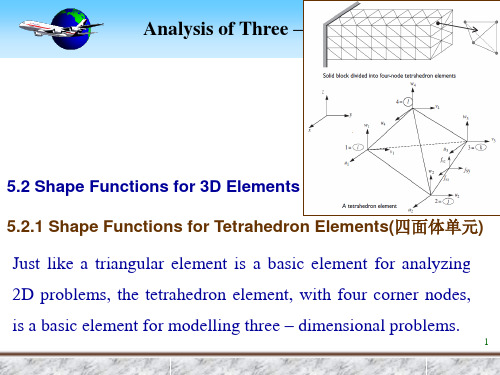
工程有限元分析英文课件:Shape Functions for 3D Elements
Ni
f1(i) (L1, L2 , L3, L4 ) f1(i) (L1i , L2i , L3i , L4i )
(5.8)
in which, f1(i) (L1, L2, L3, L4 ) denotes the left side of the equation for
one plane that pass through the remote nodes of node i, i.e.,
在右手坐标中,要使得右手螺旋在按照1-2-3的转向转动时是向4的方向前进。3
Volume CAonoardlyisnisatoefsT(Nhraeteu–r体aDl积iCm坐oe标onrs(d自ioin然naa坐lteP标sro))blems
To develop the shape functions for a tetrahedron element, we make
Analysis of Three – Dimensional Problems
Corresponding to node 1
f (1)
1
(
L1
,
L2 ,
L3, L4 )
L1
0
L1=0
Considering that L11 1, L21 L31 L41 0 , thus
Similarly
N1
8
AVnoalluysmiseoCf Tohorredein–aDteims ensional Problems
To get a2,b2, c2 and d2 we permute the indices(下标序列 改变) but must determine the proper sign(正确的符号) by
有限元分析经典课件
有限元分析经典课件1. 简介有限元分析(Finite Element Analysis, FEA)是一种以数值模拟方法为基础,通过离散化处理求解结构力学问题的工程方法。
本课件将介绍有限元分析的基本原理和常用的应用领域。
2. 有限元分析的基本原理2.1 有限元方法概述有限元方法(Finite Element Method, FEM)是有限元分析的基础理论和计算方法。
本部分将介绍有限元方法的基本概念、基本步骤、离散化处理等内容。
2.2 有限元网格划分有限元网格划分是有限元分析的关键步骤,它将结构离散化为有限个小单元。
本部分将介绍有限元网格划分的方法、常用网格类型以及网格质量评价的方法。
2.3 有限元方程与加载有限元方程是描述结构力学问题的关键方程。
本部分将介绍有限元方程的推导过程,以及加载条件的处理方法。
2.4 有限元解与后处理有限元解是通过有限元分析得到的结构响应结果。
本部分将介绍有限元解的计算方法以及后处理方法,包括位移、应力、应变等结果的计算和可视化展示。
3. 有限元分析的应用案例3.1 结构力学分析结构力学分析是有限元分析的主要应用之一。
本部分将通过实例演示有限元分析在结构力学分析中的具体应用,包括静力学分析、动力学分析等。
3.2 热力学分析热力学分析是有限元分析的另一个重要应用领域。
本部分将通过实例演示有限元分析在热力学分析中的具体应用,包括热传导、热稳定性等问题的分析。
3.3 流体力学分析流体力学分析是有限元分析的扩展应用领域之一。
本部分将通过实例演示有限元分析在流体力学分析中的具体应用,包括流体流动、压力分布等问题的分析。
4. 有限元分析软件的介绍有限元分析软件是进行有限元分析的工具,市场上有多种成熟的有限元分析软件可供选择。
本部分将介绍一些常用的有限元分析软件,包括Ansys、Abacus等。
5. 总结有限元分析作为一种重要的数值模拟方法,已广泛应用于不同领域的工程问题。
本课件从理论原理到实际应用都进行了全面的介绍,相信对有限元分析的学习和应用都有很大帮助。
工程有限元分析英文课件:Shape Functions for 3D Elements
L1 L2 L3 L4 1
(5.2)
The relation between volume coordinates and Cartesian
coordinates can be given as follows:
1 Li 6V (ai bi x ci y di z) i 1, 2, 3, 4
在右手坐标中,要使得右手螺旋在按照1-2-3的转向转动时是向4的方向前进。3
Volume CAonoardlyisnisatoefsT(Nhraeteu–r体aDl积iCm坐oe标onrs(d自ioin然naa坐lteP标sro))blems
To develop the shape functions for a tetrahedron element, we make
L3
V3 V
VolP412 , Vol1234
L2
V2 V
VolP341 Vol1234
L4
V4 V
VolP123 Vol1234
(5.1)
where Vi - the volume of the tetrahedron formed by the point P
and the nodes other than the node i (i = 1,2,3,4)
8
AVnoalluysmiseoCf Tohorredein–aDteims ensional Problems
4
DefinAitnioanlyosifsVoofluTmhereCeo–oDrdiimnaetnessional Problems
Four internal tetrahedrons having a common apex P (公共锥顶)
- 1、下载文档前请自行甄别文档内容的完整性,平台不提供额外的编辑、内容补充、找答案等附加服务。
- 2、"仅部分预览"的文档,不可在线预览部分如存在完整性等问题,可反馈申请退款(可完整预览的文档不适用该条件!)。
- 3、如文档侵犯您的权益,请联系客服反馈,我们会尽快为您处理(人工客服工作时间:9:00-18:30)。
n
1 2 x 3 y 4 z u(x, y, z) Ni 1 2 xi 3 yi 4 zi
i 1
2
Analysis of Three – Dimensional Problems
n
1 2 x 3 y 4 z u(x, y, z) Ni 1 2xi 3 yi 4zi i 1
elements.
0
Analysis of Three – Dimensional Problems
Consider a three - dimensional element having n nodal points.
For the rigid - body movement in x - direction we require the
(5.27)
4
Analysis of Three – Dimensional Problems
5.3.2 Strain – Displacement Relations
For a three – dimensional analysis we require all the six
strain components, that is x , y , z , yz , zx and xy .
displacement relations are given by
x
u x
n i 1
Ni x
ui
y
v y
n i 1
Ni y
vi
z
w z
n i 1
Ni z
wi
yz
v z
w y
n i 1
Ni z
vi
n i 1
Ni y
wi
zx
w x
u z
n i 1
Ni x
wi
n i 1
Ni z
following:
u(x, y, z) 1 2x 3 y 4z
(5.23)
where all the alphas are constants. But for the 3D n - node
element we can say the x component of displacement at any point
n
Ni 1
i 1
n
Ni xi x
i 1
n
Ni yi y
i 1
n
Ni zi z
i 1
(5.26)
3
Analysis of Three – Dimensional Problems
n
Ni xi x
i 1
n
Ni yi y
i 1
n
Ni zi z
i 1
Above three conditions are the mapping formulations(映
象公式) for isoparametric elements and hence are satisfied
when we use isoparametric elements. We only need to
ensure that for the shape functions
n
Ni 1
i 1
This becomes
1
2
x
3
y
4z
n
N
i
1
n
Ni
xi
2
n
Ni
yi
3
n
Ni zi 4
i1
i1
i1
i1
Equating coefficients(使系数相等), we come up with necessary
conditions for rigid – body movement and constant strain, that is
smaller; ②The displacement field for an element must reflect rigid –
body motion when the nodal displacements are compatible
with rigid – body motion.
If these convergence requirements are satisfied in the parent elements, they will prevail(奏效) in the curved geometry of the
The element strains are obtained in terms of derivatives of element displacements with respect to the Cartesian coordinates.
5
For a n – nodeAntharelyesi-s odfimTehnrsieoena–l Deilmemeennst,iotnhael Pstrraoibn le–ms
ui
xy
u y
v x
n i 1
Ni y
ui
n i 1
Ni x
vi
(5.34)
u
v
n
ui
Ni ( ,,
) vi
w i1
wi
6
Analysis of Three – Dimensional Problems
Strain – Displacement Transformation
u(xi , yi , zi ) ui 1 2 xi 3 yi 4 zi
(5.25)
n
Now replacing the ui in u(x, y, z) Niui , we have i 1
n
u(x, y, z) Ni 1 2 xi 3 yi 4 zi i 1
Considering u 1 2 x 3 y 4 z ,thus
n
u(x, y, z) Niui i 1
where ui denotes the nodal value of u(x, y, z) .
(5.24)
1
Analysis of Three – Dimensional Problems
At any node i, we then require that
Analysis of Three – Dimensional Problems
A Comment on Convergence for 3D Curved Elements
As we know, the interpolation functions must be such that ① Constant strain is maintained as the elements are made