球阀使用说明书英文版(ball valve)
Series 3ABV自动球阀说明说明书
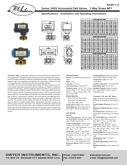
®The Series 3ABV incorporates a standard port valve for great flow rates with mini-mal pressure drop. Features include a blowout proof stem for added safety and rein-forced TFEseats and seals for longer life and leak-free operation. The four seat design allows for high cyclic capabilities and tight shut-off in any position. Perfect for mixing or diverting services in the food and chemical processing industries.The 3ABV is an economical automated valve package with either an electric or pneu-matic actuator. Electrically actuated models are weatherproof, NEMA 4, powered by standard 115 VAC supply, and are available in either two-position or proportional con-trol. Two-position actuators use the 115 VAC input to drive each of the valve ports open or closed, while the modulating actuator accepts a 4-20 mA input for infinite valve positioning. Actuator features include thermal overload protection to withstand stall conditions, visual position indication, and a permanently lubricated gear train.The pneumatic double acting actuator uses an air supply to drive each of the actua-tor ports. The actuator has two supply ports with one driving the valve stem clock-wise, the other for counterclockwise rotation. Spring return pneumatic actuators use the air supply to drive the valve stem in one direction, and internally loaded springs return the valve to its original position. Also available is the SV3 solenoid valve to electrically switch the supply pressure between the air supply ports. Actuators are constructed of anodized aluminum and are epoxy coated for years of corrosion free service.SPECIFICATIONSService:Compatible liquids, gases or steam.Body:3-way.Line Size:1/4˝ to 2˝.End Connections:Female NPT.Pressure Limits:1/4˝ to 1-1/4˝: 435 psi (30 bar) WOG, 1-1/2˝: 232 psi (16 bar)WOG, 2˝: 145 psi (10 bar) WOG. 100psi (6.9 bar) SWP .Wetted Materials:Body, End Cap, Stem: Brass.Ball: Brass, Chrome Plated.Seat, Stem Seal: TFE.Temperature Limits:320°F (160°C).Other Materials:Body Seal, Body O-ring, Stem O-ring: Fluoroelastomer.ACTUATORS ElectricPower Requirements: 120 VAC, 50/60Hz, single phase. Optional 220 VAC, 24VAC, 12 VDC, and 24 VDC.Power Consumption:(Locked RotorCurrent): Two Position: 1/4˝ to 3/4˝:.55A, 1˝ to 2˝: .75A. Modulating: 1/4˝ to 3/4˝: .55A, 1˝ to 2˝: .75A.Cycle Time:(per 90°): Two Position:1/4˝ to 3/4˝: 2.5 sec., 1˝ to 2˝: 5 sec.Modulating: 1/4˝ to 3/4˝: 2.5 sec., 1˝ to2˝: 5 sec.Duty Cycle:Two Position: 1/4˝ to 3/4˝:75%, 1˝ to 2˝: 25%. Modulating: 75%.Enclosure Rating:NEMA 4. Optional NEMA 7.Housing Material: Aluminum with ther-mal bonding polyester powder finish.Temperature Limit:0 to 150°F (-18 to 65°C).Conduit Connection:1/2˝ female NPT.Modulating Input:4 to 20 mA.Standard Features:Manual override and visual position indicator except modulating units.Pneumatic “DA” and “SR” Series Type: DA series is double acting and SR series is spring return (rack and pin-ion).Normal Supply Pressure:80 psi (5.5bar).Maximum Supply Pressure:120 psig (8 bar).Air Connections:DA/SR1 to 5: 1/8˝female NPT, all other sizes: 1/4˝ femaleNPT.Air Consumption:(per stroke) DA1:2.32 cu. in.; DA2, SR2: 9.34 cu. in.;DA3, SR3: 17.21 cu. in.; DA4, SR4:20.5 cu. in.; SR5: 39.54 cu. in. Cycle Time: (per 90°) DA1: .03 sec.;DA2: .04 sec.; DA3: .08 sec.; DA4: .12sec.; SR2: .09 sec.; SR3: .14 sec.; SR4:.22 sec.; SR5: .33 sec.Housing Material:Anodized aluminumbody and epoxy coated aluminum endcaps.Temperature Limit:-4 to 180°F(-20 to 82°C).Accessory Mounting: NAMUR stan-dard.Standard Features:Visual position indi-cator.Page 2I. BASIC INSTALLATION1. Operate valve manually and place in the open position. (NOTE: ALL ELECTRIC ACTUATORS ARE SHIPPED IN THE OPEN POSITION.)2. Remove any mechanical stops the valve might have. (DO NOT REMOVE ANY PARTS NECESSARY FOR THE PROPER OPERATIONOF THE VALVE, SUCH AS THE PACKING GLAND, PACKING NUT, ETC.)3. Ensure that the actuator output shaft and valve stem are aligned properly. If they are not, operate the valve manually until they are correct.4. Mount actuator to valve. Do not tighten nuts and bolts at this time.5. Remove actuator cover.6. Bring power to the actuator. CAUTION: Make sure power is OFF at the main box.7. Wire the actuator per the diagram attached to the inside of the cover. Special actuators (those with positioner boards, etc.) will have diagrams enclosed inside the cover.8. Securely tighten bolts used to mount the actuator to a mounting bracket or directly to the valve mounting pad if it is ISO5211 compliant.9. Cycle the unit several times and check the open and closed positions of the valve. Cams are pre-adjusted at the factory; due to the variety of valve designs and types, however, slight adjustments might be required. (SEE II and III).10. Replace cover and tighten screws.II. TO SET THE OPEN POSITION1. Cycle the valve to the open position by applying power to terminals #1 and #2.The top cam and switch control this position. In the open position, the set screw in the top cam will be accessible.2. If the valve is not open completely:A. Slightly loosen the 8-32 x 1/4” set screw on the top cam.B. Rotate the cam clockwise (CW) by hand until the switchmakes contact. Contact is made when a slight click can be heard. By making incremental CW movements of the topcam, the valve can be positioned precisely in the desired position.C. When the top cam is set, tighten the set screw securely.3. If the valve opens too far:A. Apply power to terminals #1 and #3. This will begin to rotate valve CW. When valve is full open and in the exact position desired, remove power from actuator.B. Loosen the set screw in the top cam.C. Rotate the top cam counterclockwise (CCW) until the switch arm drops off the round portion of the cam onto the flat section. A slight click can be heard as the switch changes state.D. Continue applying power to terminals #1 and #3 until valve is in the desired position.III. TO SET THE CLOSED POSITION1. Apply power to terminals #1 and #3 to move the valve toward the closed posi-tion. The bottom cam and switch control the closed position. In the closed position,the set screw in the bottom cam will be accessible.2. If the valve is not closed completely:A. Slightly loosen the 8-32 x 1/4” set screw on the bottom cam.B. Rotate the cam counter-clockwise (CCW) by hand until the switch makes contact. Contact is made when a slight click can be heard. By making incremental CCW move-ments of the bottom cam, the valve can be positioned pre-cisely in the desired position.C. When the top cam is set, tighten the set screw securely.3. If the valve closes too far:A. Apply power to terminals #1 and #2. This will begin torotate valve CCW. When valve is fully closed and in the exact position desired, remove power from actuator.B. Loosen the set screw in the top cam.C. Rotate the top cam clockwise (CW) until the switch arm drops off the round portion of the cam onto the flat section.A slight click can be heard as the switch is no longer mak-ing contact with the round part of the cam.D. Continue applying power to terminals #1 and #3 until valve is in the desired position.IV. MAINTENANCEOnce the actuator has been properly installed, it requires no maintenance. The gear train has been permanently lubricated and in most cases will never be dis-turbed. In the event it becomes necessary to open the gear box for any reason,however, Darina ®#2 grease is recommended for re-lubricating.V. DUTY CYCLEMost standard electric actuators are rated for 25% duty cycle at 100% ambient temperature at the rated torque.VI. THERMAL OVERLOADAll actuators are equipped with thermal overload protection to guard the motor against damage due to overheating.VII. MECHANICAL OVERLOADAll actuators are deigned to withstand stall conditions. It is not recommended to subject the unit to repeated stall conditions.VIII. SPARE PARTSWhen ordering parts, please specify:A. Model #B. Serial #C. Part Description Recommended spare parts include:A. Standard actuator: set of cams and switches.B. Actuators w/positioner: set of cams and switches; 1K potentiometer; valve posi-tioner board.IX. NEMA 7 ELECTRIC ACTUATORSIn general, operation and maintenance of a NEMA 7 electric actuator is no differ-ent that of a NEMA 4 actuator. However, some precautions must be followed:1. DO NOT under any circumstances remove the cover of the actuator while in a hazardous location. Removal of the cover while in a hazardous location could cause ignition of hazardous atmospheres.ELECTRIC ACTUATORSERIES 3ABV AUTOMATED BALL VALVES - 3-WAY BRASSL-Port 3.263.504.207.0012.8318.6729.7543.76T-Port 3.504.085.027.7014.2419.7230.6944.58Model*3ABV1DA1003ABV1DA1013ABV1DA1023ABV1DA1033ABV1DA2043ABV1DA2053ABV1DA3063ABV1DA407Model*3ABV1SR2003ABV1SR2013ABV1SR2023ABV1SR2033ABV1SR3043ABV1SR3053ABV1SR4063ABV1SR507Model*3ABV1U11003ABV1U11013ABV1U11023ABV1U11033ABV1U12043ABV1U12053ABV1U12063ABV1U1307Model*3ABV1V11003ABV1V11013ABV1V11023ABV1V11033ABV1V12043ABV1V12053ABV1V12063ABV1V1307Cv Double Acting Pneumatic Spring Return PneumaticTwo Position ElectricModulating Electric* Complete model includes Port Configuration - see chart below .Size(in.)1/4˝3/8˝1/2˝3/4˝1˝1-1/4˝1-1/2˝2˝Page 3PNEUMATIC ACTUATORNOTE:For optimal operation, 3ABV actuators should be run with a supply of clean,lubricated air.SPRING RETURN ACTUATORSAir to PORT 2 (the right hand port) causes the actuator to turn CCW. Loss of air to PORT 2 causes air to exhaust and the actuator turns CW. This is the FAIL CLOSE operation.DOUBLE ACTING ACTUATORSAir to PORT 2 (the right hand port) causes the actuator to turn CCW. Air to PORT 1 (the left hand port) causes the actuator to turn CW.DISASSEMBLING STANDARD ACTUATORSIMPORTANT:Before beginning disassembly, ensure that the air supply to the actu-ator has been disconnected, all accessories have been removed and that the actu-ator has been dismounted from the valve.1. Loosen the end cap fasteners (22) with a wrench (size varies depending on actu-ator model). On the spring return actuator, alternate 3 to 5 turns on each fastener until the springs are completely decompressed. Use caution in removing the cap since the springs are under load until the fasteners are fully extended.2. Remove the pinion snap ring (10) with a lock ring tool. The indicator (7) may now be removed.3. Turn the pinion shaft (2) CCW until the pistons are at the full end of travel.Disengage the pistons (11) from the pinion. (NOTE: Low pressure air--3 to 5 P .S.I.MAXIMUM--might be required to force the pistons completely from the body.) Note the position of the pistons before removing them from the actuator body. The part numbers of the pistons are located on the side and should be right-side up on an actuator with a standard orientation.4. Remove the pinion through the bottom of the actuator. The actuator is now com-pletely disassembled. All replacement parts may now be put in. W.E. Anderson rec-ommends that all wear parts (3, 4, 5, 6, 12, 13, 14) be replaced before reassem-bly.REASSEMBLING STANDARD ACTUATORSIMPORTANT: Be sure that the actuator surfaces are free of grit and scratch-es before reassembling.1. Apply a light film of grease to all o-rings and the pinion before replacing.2. Put the pinion (2) back through the actuator with the flats of the pinion shaft run-ning parallel with the body.3. When reassembling the actuator, make sure that the piston racks are square to the actuator body and returned to their original orientation. (NOTE: The normal operation of all BV pneumatic actuators is FAIL CLOSED. To change the orienta-tion to FAIL OPEN, rotate the racks 180º to create a reverse operation.)4. When replacing springs in a spring return actuator, ensure that the springs are replaced in their identical position in the end cap from which they were removed.(NOTE: In some circumstances, you might want to change the standard 80 pound spring set to fit your application and available air pressure. Changing the spring sets on BV pneumatic actuators requires no special tools. Please refer to the spring combination torque chart in our catalog for the inner and outer spring com-binations that will allow you to operate with the spring set that you desire.)4. Seal the end caps with a petroleum lubricant and bolt to actuator body.5. Check the seal of the actuator by covering seal areas (pinion, end caps) with soapy water and using low pressure air to the actuator to ensure that no bubbles are produced.PNEUMATIC ACTUATORXI. TROUBLESHOOTING2. DO NOT under any circumstances use a NEMA 7 electric actuator in a haz-ardous location that does not meet the specifications for which the actuator was designed.3. Always mount and cycle test the actuator on the valve in a non-hazardous loca-tion.4. When removing the cover, care must be taken not to scratch, scar of deform the flame path of the cover and base of the actuator, since this will negate the NEMA rating of the enclosure.5. When replacing the cover on actuators rated for both NEMA 4 & 7, take care that the gasket is in place to assure proper clearance after the cover is secured. After the cover screws are tightened, the clearance between the cover and the base should be checked. A .002” thick by 1/2” wide feeler gauge is used for this; it must not enter between the two mating faces more than .125".6. All electrical connections must be in accordance with the specifications for which the unit is being used.7. Should the unit ever require maintenance, remove from the hazardous location before attempting to work on the unit.If the actuator is in a critical application, it is advisable to have a standby unit in stock.©Copyright 2014 Dwyer Instruments, Inc.Printed in U.S.A. 4/14FR# RV-443400-50 Rev.2Page 4PNEUMATIC ACTUATOR PARTS LIST1. Extruded aluminum housing2. Nickel plated steel anti-blowout pinion3. NBR 70 lower pinion O-ring ◊4. PTFE pinion spacer ring ◊5. NBR 70 top pinion O-ring ◊6. PTFE cam spacer ring ◊7. SS indicator cam8. Nylon position indicator 9. SS pinion washer 10. Pinion snap ring11. Die cast aluminum piston 12. Piston O-ring bushing ◊13. PTFE antifriction ring ◊14. PTFE piston thrust block ◊15. SS stop bolt retaining nut 16. SS stop bolt 17. External spring*18. Internal spring*19. Die cast aluminum end cap (left)20. Die cast aluminum end cap (right)21. NBR end cap seats 22. SS end cap bolt*spring return actuators only ◊parts subject to wear. Please contact the factory or your W.E. Anderson distribu-tor for replacement kits.MAINTENANCEThe Series 3ABV Automated Balll Valves are not field serviceable and should be returned if repair is needed (field repair should not be attempted and may void war-ranty). Be sure to include a brief description of the problem plus any relevant appli-cation notes. Contact customer service to receive a return goods authorization number before shipping.Darina ®is a registered trademark of Shell Oil Company.。
True Union 2000 球阀和联接系统用户指南说明书
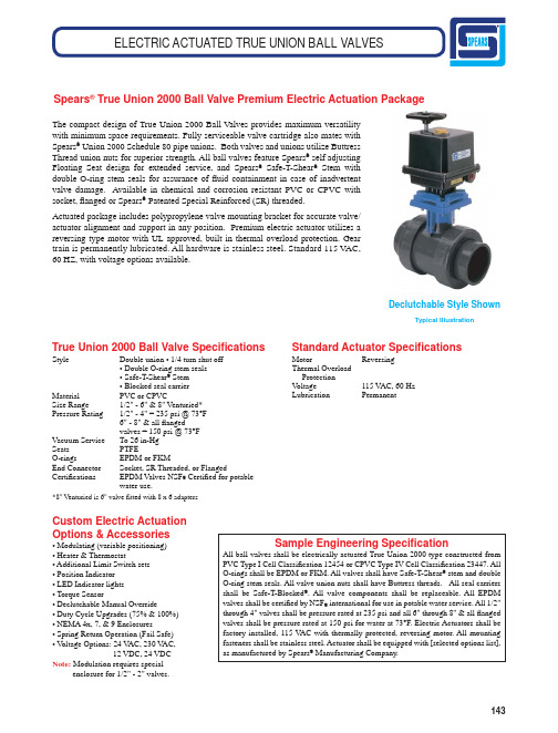
143The compact design of True Union 2000 Ball Valves provides maximum versatility with minimum space requirements. Fully serviceable valve cartridge also mates with Spears ® Union 2000 Schedule 80 pipe unions. Both valves and unions utilize Buttress Thread union nuts for superior strength. All ball valves feature Spears ® self adjusting Floating Seat design for extended service, and Spears ® Safe-T-Shear ® Stem with double O-ring stem seals for assurance of fl uid containment in case of inadvertent valve damage. Available in chemical and corrosion resistant PVC or CPVC with socket, fl anged or Spears ® Patented Special Reinforced (SR) threaded.Actuated package includes polypropylene valve mounting bracket for accurate valve/actuator alignment and support in any position. Premium electric actuator utilizes a reversing type motor with UL approved, built in thermal overload protection. Gear train is permanently lubricated. All hardware is stainless steel. Standard 115 VAC,60 HZ, with voltage options available.Spears ® True Union 2000 Ball Valve Premium Electric Actuation Package True Union 2000 Ball Valve Speci fi cationsStyle Double union • 1/4 turn shut off• Double O-ring stem seals• Safe-T-Shear ® Stem• Blocked seal carrierMaterial PVC or CPVCSize Range 1/2" - 6" & 8" Venturied*Pressure Rating 1/2" - 4" = 235 psi @ 73°F6" - 8" & all fl angedvalves = 150 psi @ 73°FVacuum Service To 26 in-HgSeats PTFEO-rings EPDM or FKMEnd Connector Socket, SR Threaded, or FlangedCerti fi cations E PDM Valves NSF ® Certi fi ed for potablewater use.*8" Venturied is 6" valve fitted with 8 x 6 adapters Standard Actuator Speci fi cations Motor Reversing Thermal Overload Protection V oltage 115 V AC, 60 Hz Lubrication PermanentCustom Electric ActuationOptions & Accessories• Modulating (variable positioning)• Heater & Thermostat• Additional Limit Switch sets• Position Indicator• LED Indicator lights• Torque Sensor• Declutchable Manual Override• Duty Cycle Upgrades (75% & 100%)• NEMA 4x, 7, & 9 Enclosures• Spring Return Operation (Fail Safe)• V oltage Options: 24 V AC, 230 V AC,12 VDC, 24 VDCNote: Modulation requires specialenclosure for 1/2" - 2" valves.Sample Engineering Speci fi cation All ball valves shall be electrically actuated True Union 2000 type constructed from PVC Type I Cell Classi fi cation 12454 or CPVC Type IV Cell Classi fi cation 23447. All O-rings shall be EPDM or FKM. All valves shall have Safe-T-Shear ® stem and double O-ring stem seals. All valve union nuts shall have Buttress threads. All seal carriers shall be Safe-T-Blocked ®. All valve components shall be replaceable. All EPDM valves shall be certi fi ed by NSF ® international for use in potable water service. All 1/2" through 4" valves shall be pressure rated at 235 psi and all 6" through 8" & all fl anged valves shall be pressure rated at 150 psi for water at 73°F. Electric Actuators shall be factory installed, 115 V AC with thermally protected, reversing motor. All mounting fasteners shall be stainless steel. Actuator shall be equipped with [selected options list], as manufactured by Spears ® Manufacturing Company.Declutchable Style ShownELECTRIC ACTUATED TRUE UNION BALL VALVESTypical Illustration。
Valves Ball 小型金属阀门说明说明书
Valves, Ball, Man
VALVES
SERIES MV
MINI BRASS BALL VALVES
Economical, Compact Design
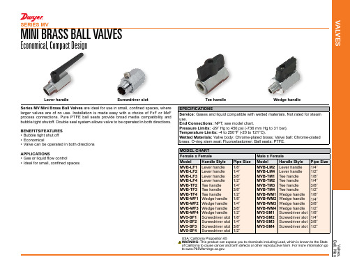
Lever handle
Screwdriver slot
Series MV Mini Brass Ball Valves are ideal for use in small, confined spaces, where larger valves are of no use. Installation is made easy with a choice of FxF or MxF process connections. Pure PTFE ball seats provide broad media compatibility and bubble tight shutoff. Double seal system allows valve to be operated in both directions.
USA: California Proposition 65 WARNING: This product can expose you to chemicals including Lead, which is known to the State of California to cause cancer and birth defects or other reproductive harm. For more information go to .
MV5-SF1 MV5-SF2 MV5-SF3 MV5-SF4
Screwdriver slot 1/8˝ Screwdriver slot 1/4˝ Screwdriver slot 3/8˝ Screwdriver slot 1/2˝
手动球阀使用说明

球阀使用说明书 Q41F 浮动式球阀球 阀 (Ball Valve)球阀是由旋塞演变而来的,它的启闭件为一个球体,利用球体绕阀杆的轴线旋转90度实现开启和关闭的目的。
球阀在管道上主要用于切断、分配和改变介质流动方向,设计成V 形开口的球阀还具有良好的流量调节功能。
球阀不仅结构简单,密封性好,而且在一定的公称通径范围内体积较、重量轻、材料耗阀门品种之一。
特别是在美、日、德、法、意、西、英等工业发达国家,球阀的使用非常广泛,使用品种和数量仍在继续扩大,并向高温、高压、大口径、高密封性、长寿命、优良的调节性能以及一阀多功能方向发展,其可靠性及其他性能指标均达到较高水平,并已部分取代闸阀、截止阀、节流阀。
随着球阀的技术进步,在可以预见的短时间内,特别是在石油天然气管线上、炼油裂解装置上以及核工业上将有更广泛的应用。
此外,在其他工业中的大中型口径、中低压力领域,球阀也将会成为主导的阀门类型之一。
球阀结构爆炸图序号名称数量1 阀盖 12 密封垫 13 四氟密封圈 24 螺帽 45 螺栓 46 球 17 阀体 18 内六角螺丝 29 四氟填料 410 压盖 111 阀杆 112 四氟圈(阀杆密封) 1另有定位片、手柄、蜗轮、电动头(视工况而定)球阀的优点是:(1) 具有最低的流阻(实际上为零)。
(2) 因在工作时不会卡住(在无润滑剂时),故能可靠地应用于腐蚀性介质和低沸点液体中。
(3) 在较大的压力和温度范围内,能实现完全密封。
(4) 可实现快速启闭,某些结构的启闭时间仅为0.05~0.1s,以保证能用于试验台的自动化系统中。
快速启闭阀门时,操作无冲击。
(5) 球形关闭件能在边界位置上自动定位。
(6) 工作介质在双面上密封可靠。
(7) 在全开和全闭时,球体和阀座的密封面与介质隔离,因此高速通过阀门的介质不会引起密封面的侵蚀。
(8) 结构紧凑、重量轻,可以认为它是用于低温介质系统的最合理的阀门结构。
(9) 阀体对称,尤其是焊接阀体结构,能很好地承受来自管道的应力。
A-T Controls 22 SERIES 直接挂载球阀值用说明和维护手册说明书

1.USE: 1.1Life of valve can be maximized if the valve is used within the rated range, in accordance with pressure, temperature, and corrosion data. 2.MANUAL OPERATION: 2.1To open or close the valve, turn the handle ¼ turn (90 degrees). A.Valve in Open Position – the handle is in parallel (in-line) with the valve or pipeline. B.Valve in Closed Position – the handle is perpendicular (crossed) with the valve or pipeline.3.DISASSEMBLING & CLEANING THE VALVE: 3.1Ball valves can trap fluids in ball cavity when it is in closed position. 3.2If the valve has been used in hazardous media, it must be decontaminated before disassembly. A.Relieve the line pressure. B.Place valve in half-open position and flush the line to remove any hazardous material from valve. C.All persons involved in the removal and disassembly of the valve should wear the proper protective clothing, such as face shield, glove, apron, etc.4.REPLACING THE THRUST WASHER, PACKING, AND SEATS 4.1Before replacing the stem seal and the packing, the pipeline must be de-pressurized. 4.2Take-off the valve from the pipeline. 4.3Place valve in its’ fully open position. 4.4Take-off end cap. 4.5Close the valve and remove the seat, body seals and ball. 4.6Remove the valve stem nut, handle, gland nut and remove the valve stem through the body cavity. 4.7Remove the stem trust washer from the stem cavity. 4.8Examine all metallic sealing surfaces such as ball, stem and end cap for damage, if the ball or stem is excessively damaged, ball and stem need to be replaced.5.RE-ASSEMBLINGHaving assured that all critical surfaces and components have been inspected, cleaned and or replaced, re-assemble can begin. 5.1Place new stem seal on stem and install the stem. 5.2Install new gland packing, bushing,gland bush, belleville washer and stem nut 5.3Tighten stem nut to torque specification in Table 1.5.4 Lightly lubricate seats and body seals using a lubricant. 5.5 Re-install end cap.A-T Controls product, when properly selected, is designed to perform its intended function safely during its useful life. However, the purchaser or user of A-T Controls products should be aware that A-T Controls products might be used in numerous applications under a wide variety of industrial service conditions. Although A-T Controls can provide general guidelines, it cannot provide specific data and warnings for all possible applications. The purchaser / user must therefore assume the ultimate responsibility for the proper sizing and selection, installation, operation, and maintenance of A-T Controls products. The user should read and understand the installation operation maintenance (IOM) instructions included with the product, and train its employees and contractors in the safe use of A-T Controls products in connection with the specific application.While the information and specifications contained in this literature are believed to be accurate, they are supplied for informative purposes only. Because A-T Controls is continually improving and upgrading its product design, the specifications, dimensions and information contained in this literature are subject to change without notice. Should any question arise concerning these specifications, the purchaser/user should contact A-T Controls.For product specifications go to /A-T Controls, Inc. • 9955 International Boulevard, Cincinnati, OH 45246 • Phone: (513) 530-5175 • Fax: (513) 247-5462 • 。
Series WE06 3-Piece NPT钢球阀值说明书

Series WE06 3-Piece NPT Stainless Steel V-Ball ValveSpecifications - Installation and Operating InstructionsBulletin V-WE06The Series WE06 3-Piece NPT Stainless Steel V-Ball Valve incorporates a V-port ball valve for impressive flow rates with minimal pressure drop. Quarter turn control ball valves are compact, lighter weight and much less expensive than comparable sized globe valves and segmented control valves. They also offer bubble tight shut off with zero leakage and can withstand high pressure drops. The 60° and 90° balls offer an equal percentage flow characteristic. W. E. Anderson’s V-port ball valves have been designed to offer maximum flow characteristics that are substantially higher than comparably sized globe valves. The natural flow pattern of ball valves increases flow rates and in many applications valves smaller than pipeline size can be used. Actuators are directly mounted creating a compact assembly for tight spaces. Limit switches can be mounted directly to the valves allowing for remote position indication. The Series WE06 can be configured with an electric or pneumatic actuator. Electric actuators are available in weatherproof or explosion-proof, a variety of supply voltages and two-position modulating control.Two-position actuators use the supply voltage to drive the valve open or close, while the modulating actuator accepts a 4-20 mA input for valve positioning. Actuators feature thermal overload protection and a permanently lubricated gear train.The pneumatic double acting actuator uses an air supply to drive the valve open and closed. The actuator has two supply ports with one driving the valve open and the other driving the valve closed. Spring return pneumatic actuators use the air supply to open the valve and internally loaded springs return the valve to the closed position. Also available is the SV3 solenoid valve to electrically switch the air supply pressure between the air supply ports for opening and closing the valve. Actuators are constructed of anodized and epoxy coated aluminum for years of corrosion freeservice.WE06-DHD00-TWE06-DDA01-TWE06-DTD01-T-AWE06-DDA01-T-AA01WE06-CTI01-T-AVALVE BILL OF MATERIALSVALVE DIMENSIONAL DRAWINGCv Valve Charts90° V-PORT – Cv60° V-PORT – Cv Pressure/Temperature Rating ChartAUTOMATED VALVE DRAWINGSWITH PNEUMATIC ACTUATORWITH ELECTRIC ACTUATORWITH EXPLOSION-PROOF ELECTRIC ACTUATORPNEUMATIC ACTUATORNote: For optimal operation, pneumatic actuators should be run with a supply of clean, lubricated air.Spring Return Actuator OperationAir to PORT 2 (the left hand port) causes the actuator to turn counterclockwise (CCW). Loss of air to PORT 2 causes air to exhaust and the actuator turns clockwise (CW). This is the FAIL CLOSE operation.Double Acting Actuators OperationAir to PORT 2 (the left hand port) causes the actuator to turn counterclockwise (CCW). Air to PORT 1 (the right hand port) causes the actuator to turn clockwise (CW).Pneumatic Actuator MaintenanceRoutine maintenance of pneumatic actuator:• Keep the air supply dry and clean• Keep the actuator surface clean and free from dust• Periodic checks should be done to make sure all fittings are tight • P neumatic actuators are supplied with lubrication to last the entire life span ofthe actuator under normal operating conditions. The outer surface of the pneumatic actuator should be clean to avoid friction or corrosion. All fittings and connections should be tight to prevent leaks during operation. Check the bolts mounting the valve to the actuator to make sure they have not come loose during shipping or installation. Make sure the valve and actuator are not rubbing or jamming against other components during operation. The actuator should be inspected annually to make sure all fittings and bolts are tight and nothing has come loose during operation.Disassembling Pneumatic ActuatorsBefore beginning disassembly, ensure that the air supply to the actuator has been disconnected, all accessories have beenremoved, and that the actuator has been disassembled from the valve.1. L oosen the end cap fasteners (23) with a wrench (size varies depending onactuator model). On the spring return actuator, alternate 3 to 5 turns on each fastener until the springs are completely decompressed. Use caution when removing the cap since the springs are under load until the fasteners are fully extended.2. R emove the pinion snap ring (13) with a lock ring tool. The indicator (12) maynow be removed.3. T urn the pinion shaft (2) counter clockwise until the pistons are at the full end oftravel. Disengage the pistons (15) from the pinion. (Note: Low pressure air--3 to 5 psi MAXIMUM--might be required to force the pistons completely from the body.) Note the position of the pistons before removing them from the actuator body. 4. R emove the pinion through the bottom of the actuator. The actuator is nowcompletely disassembled.Be sure the actuator surfaces are free of debris and scratches before reassembling.1. Apply a light film of grease to all O-rings and the pinion before replacing.2. P ut the pinion (2) back through the actuator with the flats of the pinion shaftrunning parallel with the body.3. W hen reassembling the actuator, make sure that the piston racks are square tothe actuator body and returned to their original orientation. (Note: The normal operation of all spring return pneumatic actuators is FAIL CLOSED. To change the orientation to FAIL OPEN, rotate the racks 180º to create a reverse operation.4. W hen replacing springs in a spring return actuator, ensure that the springs arereplaced in their identical position in the end cap from which they were removed. (Note: In some circumstances, you might want to change the standard 80 pound spring set to fit your application and available air pressure.5. Seal the end caps with a petroleum lubricant and bolt to actuator body.6. C heck the seal of the actuator by covering seal areas (pinion, end caps) withsoapy water and using low pressure air to the actuator to ensure that no bubbles are produced.Reassembling Pneumatic ActuatorsWhen working on the Actuator/Valve assembly, disconnect the air or power supply to the actuator. Spring return actuators/valves may change position if power fails or is removed. Never insert any object or body part into the valve body. Severe injury may occur.Pneumatic Actuators Bill of MaterialsELECTRIC ACTUATORSElectric Installation1. Operate valve manually and place in the open position.2. R emove any mechanical stops the valve might have. (DO NOT REMOVE ANYPARTS NECESSARY FOR THE PROPER OPERATION OF THE VALVE, SUCH AS THE PACKING GLAND, PACKING NUT, ETC.)3. E nsure that the actuator output shaft and valve stem are aligned properly. If theyare not, operate the valve manually until they are correct.4. Remove actuator cover.5. B ring power to the actuator. CAUTION: Make sure power is OFF at the mainbox.6. W ire the actuator per the diagram attached to the inside of the cover. Specialactuators (those with positioner boards, etc.) will have diagrams enclosed inside the cover.7. S ecurely tighten bolts used to mount the actuator to a mounting bracket ordirectly to the valve mounting pad if it is ISO5211 compliant.8. C ycle the unit several times and check the open and closed positions of thevalve. Cams are pre-adjusted at the factory; due to the variety of valve designs and types however, slight adjustments might be required.9. Replace cover and tighten screws.To Set The Open Position1. C ycle the valve to the open position by applying power to terminals. The top camand switch control this position. In the open position, the set screw in the top cam will be accessible.2. I f the valve is not open completely:A. Slightly loosen the set screw on the top cam.B. R otate the cam clockwise (CW) by hand until the switch makes contact.Contact is made when a slight click can be heard. By making incremental CW movements of the top cam, the valve can be positioned precisely in the desired position.C. When the top cam is set, tighten the set screw securely.3. If the valve opens too far:A. A pply power to terminals. This will begin to rotate valve CW. When valve isfully open and in the exact position desired, remove power from actuator.B. Loosen the set screw in the top cam.C. R otate the top cam counterclockwise (CCW) until the switch arm drops offthe round portion of the cam onto the flat section. A slight click can be heard as the switch changes state.D. Continue applying power to terminals until valve is in the desired position.To Set The Closed Position1. A pply power to terminals to move the valve toward the closed position. Thebottom cam and switch control the closed position. In the closed position, the set screw in the bottom cam will be accessible.2. If the valve is not closed completely:A. Slightly loosen the set screw on the bottom cam.B. R otate the cam counterclockwise (CCW) by hand until the switch makescontact. Contact is made when a slight click can be heard. By making incremental CCW movements of the bottom cam, the valve can be positioned precisely in the desired position.C. W hen the top cam is set, tighten the set screw securely.3. If the valve closes too far:A. A pply power to terminals. This will begin to rotate valve CCW. When valve isfully closed and in the exact position desired, remove power from actuator.B. Loosen the set screw in the top cam.C. R otate the top cam clockwise (CW) until the switch arm drops off the roundportion of the cam onto the flat section. A slight click can be heard as the switch is no longer making contact with the round part of the cam.D. Continue applying power to terminals until valve is in the desired position.Electric Actuators Wiring Diagram: ACT-TI & ACT-MIWiring Diagrams forTI01-A to TI05-A: 110 VAC, TI01-B to TI05-B: 220 VAC, TI01-C to TI05-C: 24 VACHOTALVE ALVEWiring Diagrams for TI01-D to TI05-D: 24 VDCOPERATION:POWER TO 1 & 2 FOR CCW ROTATION POWER TO 3 & 4 FOR CW ROTATION TERMINALS 5 & 6 FOR FIELD LIGHT INDICATION CONNECTIONSW.#1 SW.#2SWITCH #1 OPEN SWITCH SWITCH #2 CLOSE SWITCHWiring Diagrams forMI01-A to MI05-A: 110 VAC, MI01-B to MI05-B: 220 VAC, MI01-C to MI05-C: 24 VACSW. 1, CLOSESW. 2, OPEN .SW. 3, CLOSE SW. 4, OPEN Wiring Diagrams forMI01-D to MI05-D: 24 VDCSW. 1, CLOSESW. 2, OPEN .SW. 3, CLOSE SW. 4, OPENElectric Actuators Wiring Diagram: ACT-TD & ACT-MDWiring Diagrams forTD01-A to TD03-A: 110 VAC, TD01-B to TD03-B: 220 VAC,TD01-C to TD03-C: 24 VACWiring Diagrams forTD01-D to TD03-D: 24 VDCWiring Diagrams forMD01-A to MD03-A: 110 VAC, MD01-B to MD03-B: 220 VAC,MD01-C to MD03-C: 24 VACNote: To speed up installation of the control wires to the ACT-MDXX modulating actuator, it is recommended to remove the control module from the actuator. The control module can be removed by removing the two mounting screws on the left and right of the control module. Install the control wires to the correct terminal points and then reinstall the control module.Electric Actuator MaintenanceOnce the actuator has been properly installed, it requires no maintenance. The gear train has been lubricated and in most cases will never be opened. Duty Cycle Definition“Duty Cycle” means the starting frequency.Formula: Running Time ÷ (Running Time + Rest Time) x 100% = duty cycle –> Rest Time = Running Time x (1 - duty cycle) ÷ duty cycleFor example: The running time is 15 seconds30% duty cycle 15 x [(1 - 30%) / 30%] = 35 –> The rest time will be 35 seconds 75% duty cycle 15 x [(1 - 75%) / 75%] = 5 –> The rest time will be 5 seconds If the duty cycle is higher, the rest time will be shortened, which means the starting frequency will be higher.Thermal OverloadAll actuators are equipped with thermal overload protection to guard the motor against damage due to overheating.Mechanical OverloadAll actuators are designed to withstand stall conditions. It is not recommended to subject the unit to repeated stall conditions.Explosion-Proof Electric Actuators1. DO NOT under any circumstances remove the cover of the actuator while in a hazardous location. Removal of the coverwhile in a hazardous location could cause ignition of hazardous atmospheres.2. D O NOT under any circumstances use an explosion-proof electric actuator in ahazardous location that does not meet the specifications for which the actuator was designed.3. A lways verify that all electrical circuits are de-energized before opening theactuator.4. A lways mount and cycle test the actuator on the valve in a non-hazardouslocation.5. W hen removing the cover, care must be taken not to scratch, scar of deform theflame path of the cover and base of the actuator, since this will negate the NEMA rating of the enclosure.6. W hen replacing the cover, take care that the gasket is in place to assure properclearance after the cover is secured. 7. A ll electrical connections must be in accordance with the specifications for whichthe unit is being used.8. S hould the unit ever require maintenance, remove from the hazardous locationbefore attempting to work on the unit. If the actuator is in a critical application, it is advisable to have a standby unit in stock.11Electric Actuators Performance Rating MAINTENANCE/REPAIRUpon final installation of the Series WE, only routine maintenance is required. The Series WE is not field serviceable and should be returned if repair is needed. Field repair should not be attempted and may void warranty.WARRANTY/RETURNRefer to “Terms and Conditions of Sale” in our catalog and on our website. Contact customer service to receive a Return Goods Authorization number before shipping the product back for repair. Be sure to include a brief description of the problem plus any additional application notes©Copyright 2022 Dwyer Instruments, Inc.Printed in U.S.A. 7/22FR# 444258-00 Rev. 412NOTES____________________________________________________________________________________________________________________________________________________________________________________________________________________________________________________________________________________________________________________________________________________________________________________________________________________________________________________________________________________________________________________________________________________________________________________________________________________________________________________________________________________________________________________________________________________________________________________________________________________________________________________________________________________________________________________________________________________________________________________________________________________________________________________________________________________________________________________________________________________________________________________________________________________________________________________________________________________________________________________________________________________________________________________________________________________________________________________________________________________________________________________________________________________________________________________________________________________________________________________________________________________________________________________________________________________________________________________________________________________________________________________________________________________________________________________________________________________________________________________________________________________________________________________________________________________________________________________________________________________________________________________________________________________________________________________________________________________________________________________________________________________________________________________________________________________________________________________________________________________________________________________________________________________________________________________________________________________________________________________________________________________________________________________________________________________________________________________________________________________________________________________________________________________________________________________________________________________________________________________________________________________________________________________________________________________________________________________________________________________________________________________________________________________________________________________________________________________________________________________________________________________________________________________________________________________________________________________________________________________________________________________________________________________________________________________________________________________________________________________________________________________________________________________________________。
浮动球阀使用说明书
SUNGO V ALVES GROUP CO.,LTD管线阀门PIPELINE V ALVE浮动球阀使用说明书FLOATING BALL VALVE OPERATING INSTRUCTIONS管线浮动球阀使用说明书 Pipeline Floating Ball Valve OperatingInstruction1、用途和性能规范:Purpose and Specification本产品是我公司按API 6D/API 608设计、制造的钢制管线浮动球阀,适用于液体、气体等介质,在管路上作启闭装置,具有密封结构可靠、先进,流阻小,启闭迅速、灵活,使用寿命长,安全可靠,维修方便等优点,可广泛的用于石油、化工、炼制、钢铁、造纸、医药等行业。
This products is our company according to the API 6D/API 608 designs and manufactures of steel pipeline floating ball valve, It is used for liquid,gas etc tubing line open or main advantages include: Reliable sealing structure、Thechnology advanced、Small liquid resistance、Flexible open and close、Long service life、Safe reliabe、Convienient maintance etc. This kind of ball valve is widely utilized in Petroleum、Chemical industry、refinement、Steel and iron、papermaking, medicine etc.产品性能规范表Performance Specification2、采用的主要标准:The main adoption standard设计制造与结构长度按API 6D/API 608的规定;Design conform to API 6D/API 608法兰型式及尺寸按ASME 的规定;Flange conform to ASME结构长度按ASME 的规定;Face to face conform to ASME阀门的温度-压力额定值按ASME 的规定;Temperature-class conform to ASME检验和试验按API 6D的规定;Test conform to API 6D防火标准按API 607/6FA的规定。
球阀(JSB)中英文操作手册
A S P E C I A L I S T I N D E S I G N&M A N U F A C T U R E O F V A L V E S目录目录 (1)Preface 前言 (2)Product Features产品特点 (3)Applicable Standards 设计规范 (4)Installation,Operation and Maintenance Instructions for V-Port Segment Control Valve – JSB Series 安装,操作和维护说明 (6)Storage 保存 (6)Preparation and preservation for storage保存的准备及维护 (6)Handling requirements处理要求 (6)Storage and preservation before installation组装前的保存及维护 (8)Installation 安装 (10)Preparation before installation安装之前的准备工作 (10)Installation Instructions安装操作 (11)Maintaince 维护 (14)Disassembly & Assembly拆卸和组装 (15)Valve disassembly阀的拆御 (16)Valve re-assembly重新组装阀 (17)A S P E C I A L I S T I N D E S I G N&M A N U F A C T U R E O F V A L V E SPreface 前言1. Please read this manual before installation or servicing.请在安装和维修阀门前阅读此操作手册2. Before installing or servicing, please ensure the line pressure has been relieved and anyhazardous fluid has been drained or purged from the system.请在安装和维修前,确保管道压力已经泄放,同时危险的流体已经排放掉。
A-T Controls 55 SERIES 全端口球阀安装与维护指南说明书
Contents1.SCOPE (2)2.INSTALLATION (2)3.VALVE OPERATION (3)4.DISASSEMBLY (3)5.ASSEMBLY (4)6.REPAIR KITS (4)1.SCOPE1.1.CAUTION1.1.1.For your safety, read this manual before installation or service.1.1.2.Before installing or servicing, please ensure the line pressure has been relieved and any hazardous fluids have beendrained or purged from the system.1.1.3.Ensure that all Lockout and Tagout procedures for the system have been properly implemented.E1.2.1.Maximum results and long life of valves can be maintained under normal working conditions and according withpressure/ temperature ratings and corrosion data chart.2.INSTALLATION2.1.GENERAL INFORMATION FOR INSTALLATION2.1.1.The valve can be installed in any position on the pipeline.2.1.2.Before installation of the valve, the pipe must be flushed clean of dirt, burrs, and welding residue, or the seats and ballsurface will be damaged. The pipe must be free from tension and in proper alignment. Check to ensure that allconnections are free from defects.2.2.INSTALLATION OF THREADED VALVESe conventional sealant, such as hemp core, Teflon, etc. on threads. Apply wrench only on the hexagon of the valveends. Tightening by using the valve body or lever can seriously damage the valve. In some applications, screwedvalves are back welded on site. These valves must be treated as per instructions for the weld end valves before backwelding.2.3.INSTALLATION OF WELDED ENDS2.3.1.Tack weld the valves on the pipe in four points on both end caps.2.3.2.With the valve in the open position, (lever to be parallel to the axis of the pipe), remove all the body bolts except one.Loosen the nut on the remaining bolt. Swing the body outside the pipe. Finish welding both end caps on the pipe.2.3.3.When cooled down, clean both end caps and body surface.2.3.4.Swing the body back in position and replace the body bolts. Tighten all nuts slightly. This operation is very importantto keep the body and end caps perfectly parallel, thus preventing distortion of end caps. Tighten body bolts evenly (seesection 5.5). Make sure that maximum tightening torque is observed. Check proper operation of the valve.3.VALVE OPERATION3.1. MANUAL3.1.1.HANDLE3.1.1.1.To OPEN the valve, turn the handle counterclockwise until the handle is parallel with the pipeline and the handlehas contacted the handle stop.3.1.1.2.To CLOSE the valve, turn the handle clockwise until the handle is perpendicular with the pipeline and the handlehas contacted the handle stop.3.1.1.3.A handle lock is incorporated into the handle. To use, slide the lock into the mounting pad, in the full open orfull closed position. Insert an appropriate size lock or hasp into the handle. If it can be performed safely, try toturn the handle to ensure that the valve has been locked properly.3.1.2.GEAR3.1.2.1.To OPEN the valve, turn the handle wheel counterclockwise. The indicator will be pointing to the open positionand stop rotating when fully opened. The flow can be adjusted by stopping the indicator anywhere between openand close.3.1.2.2.To CLOSE the valve, turn the handle wheel clockwise. The indicator will be pointing to the close position andthe hand wheel will stop rotating when fully closed. The flow can be adjusted by stopping the indicatoranywhere between open and close.3.2.AUTOMATED3.2.1.A-T Controls 55 Series Ball Valves can be mounted with quarter turn actuators. Valves with actuators shall be checkedfor proper valve stem alignment. Angular or linear misalignment may result in high operational torque and unnecessarywear on the valve stem. See the actuator IOM for information on operating the actuator.4.DISASSEMBLYWARNINGCAUTION, FLUIDS CAN BE TRAPPED IN THE BODY OF THE VALVE, POSSIBLY UNDER HIGH PRESSURE. FOR YOUR SAFETY, IT IS IMPORTANT THAT PRECAUTIONS ARE TAKEN BEFORE REMOVAL OF THE VALVE FROM THE LINE OR ANY DISASSEMBLY.4.1.Remove actuator or gear if equipped.4.2.Care should be taken to not damage the surface finish of the valve components,4.3.Remove the ends (2) from the body (1) by removing the body bolts (14), body nuts (17), and lock washers (18).4.4.Remove the seats (8) and body gaskets (13) from both sides of the body (1). Once removed, with the valve in the fullyclosed position, the ball (3) should slide freely out of the body (1).4.5.If equipped, remove the handle nut (21), handle (7), and the handle stop assembly (15).4.6.While holding the stem (4) stationary, remove the packing nut (5). Once removed, the locking saddle (12), Bellevillewashers (6), and the packing bushing (9) should be free to remove.4.7.While holding the bottom of the stem (4), push the stem (4) through the inside of the valve body (1).4.8. Remove the packing set (10) and the thrust washer (11).4.9.Inspect all components for damage and, if necessary, clean or replace.5.ASSEMBLY5.1.Care should be taken to not damage the surface finish of the valve components.5.2.Place thrust washer (11) on the stem (4) and install it by going through the body (1). Insert V-style packing set (10) overstem (4) with the V pointing away from the valve (see Bill of Materials for correct orientation).5.3.Install the packing gland (10), Belleville washers (6), the locking saddle (12), and the packing nut (5). While holding thestem (4), tighten the packing nut (5) to the torque listed in the Fastener Torque Chart. Tighten further if needed in order to be able to place the locking saddle (12) over the packing nut (5).5.4.Ensure the stem (4) is in the closed position with the body tang parallel with the flow of the valve. Insert a seat (8) and bodygasket (13) in one side of the body (1). Carefully slide the ball (3) into the body (1) and insert the other seat (8) and body gasket (13).5.5.Assemble ends (2) onto body (1). Insert all body bolts (14), body nuts (17) and lock washers (18) into valve and tighten tofinger tight, making sure that the ends (2) are flat against the body (1). Tighten all body bolts (on both sides for 2-1/2” thru 4”) from the nut (17) to 50% of the max bolt torque in a star pattern. Check each body bolt (14) torque and tighten a final time to the max torque of the body bolts. It is acceptable for the torque to relax slightly over time due to relaxation of the polymer components, but the valve will still seal properly. If leakage is detected, repeat the steps for tightening the body bolts (14).5.6.If required, assemble the locking device (20), handle stop (15), handle (7), and the handle nut (21).6.REPAIR KITSRepair kits are available to replace all soft goods. See Bill of Materials for components that are included in the repair kits.7.BILL OF MATERIALSA-T Controls product, when properly selected, is designed to perform its intended function safely during its useful life. However, the purchaser or user of A-T Controls products should be aware that A-T Controls products might be used in numerous applications under a wide variety of industrial service conditions. Although A-T Controls can provide general guidelines, it cannot provide specific data and warnings for all possible applications.The purchaser / user must therefore assume the ultimate responsibility for the proper sizing and selection, installation, operation, and maintenance of A-T Controls products. The user should read and understand the installation operation maintenance (IOM) instructions included with the product and train its employees and contractors in the safe use of A-T Controls products in connection with the specific application.While the information and specifications contained in this literature are believed to be accurate, they are supplied for informative purposes only.Because A-T Controls is continually improving and upgrading its product design, the specifications, dimensions and information contained in this literature are subject to change without notice. Should any question arise concerning these specifications, the purchaser/user should contact A-T Controls.For product specifications go to https:///Downloads/。
PERAR全焊接球阀安装操作维护手册中英文版
TM
Checked
M.P
Approved G.P. MM-IE-02-002
2.0 INSTALLATION AND OPERATION
Sheet 2 of 11
2.1 Installation
2.1.1 2.1.2 2.1.3
Be sure that the valve is in the "OPEN" position. Remove the flange covers. Install the valve on the pipework. Strictly avoiding any operation of the valve until cleaning of pipework is complete.
6.1 Rotate the ball (Pos.04) in closed position. 6.2 Unscrew the stem key cap screw (Pos.69) and remove the stem key (Pos.70).
Then unscrew the adapter plate nuts (Pos.17a) and remove the adapter plate (Pos.99). 6.3 Unscrew the gland plate nuts (Pos.17a) and remove the gland plate and
“WB Std.” TYPE
ܼ⛞䯔ԧᅮ⧗ᓣ⧗䯔“WB Std”ൟ ᅝ㺙ǃ᪡㓈ᡸݠ
INSTALLATION, OPERATION AND MAINTENANCE MANUAL FOR TRUNNION BALL VALVE “WB Std” TYPE
- 1、下载文档前请自行甄别文档内容的完整性,平台不提供额外的编辑、内容补充、找答案等附加服务。
- 2、"仅部分预览"的文档,不可在线预览部分如存在完整性等问题,可反馈申请退款(可完整预览的文档不适用该条件!)。
- 3、如文档侵犯您的权益,请联系客服反馈,我们会尽快为您处理(人工客服工作时间:9:00-18:30)。
Product Manual
- Operation and Maintenance Manual Product Name:API 6D Ball Valve
January 2012
1Scope
This manual covers manually/motor/pneumatic operated seat supported /trunnion supported ball valve having tow/three pieces body with nominal sizes DN 15mm-1200mm (1/2”-48”) and class ranges PN1.6MPa-10MPa(ANS1 class 150-2500).
Valve ends may be threaded, flanged, butt-welded or socket
2 Applications
2.1 Ball valves are used to open/close the flow in pipeline.
2.2 The nature of applicable fluid depends on valve material:
2.2.1 Carbon steel valve applies to non-corrosive fluid, such as water, vapor or oil etc. 2.3 Temperature range depend on sent material:
PTFE ≤130℃
RPTFE ≤160℃
PPL ≤300℃
NYLON ≤121℃
3. standard:
Basic design API 6D-2008
Inspe crlon tesring BS EN 12266.1-2003
End flange ASME B16.5-2009
TEMP. & PRESSURE ASME B16.34-2009
Face toface ASME B16.10-2009
Main parts and materials ASME materials, see Table 1
Figure 1:Trunnion Ball Valve
4 Structure
4.1 Ball Valve structure is shown in Fig. 1.
4.2 List the major components and materials shown in Table 1:
Table 1: Major Parts and Materials
-29℃~38℃working pressure(bar)
50℃working pressure(bar)
100℃working pressure(bar)
121℃working pressure(bar)
6 Operation
The valve can be manually operated by using the handle for manually operated valves or motor-operated by the electric actuator for motor operated valves or pneumatic operated by pneumatic actuator for pneumatic operated valves. The valve open or closes by turning the ball. Clockwise turning to 90ºresults in valve open.
6.1 The manually operated valve is opened when the handle and the position mark on stem end are parallel to pipeline. When that is perpendicular to the pipeline, the valve is closed.
6.2 For motor/pneumatic operated valves, valve open/close is indicated by the positioner on the electric/pneumatic actuator.
7 Storage, maintenance, installation and service
7.1 The valve should be stored in dry room with good ventilation. Valve ends should be covered.
7.2 For valve stored for a long period of time, regular checkup is required to ensure that the valves are in good conditions. Foreign particles should be removed and special care should be taken to keep the valve seat sealing surface clean and prevent any damage of sealing surface.
7.3 Check the conformance of valve identification to the service requirements prior to installation.
7.4 Check the cleanness of the valve cavity and sealing surface and sealing surface and wipe off any dirt with white cloth prior to installation.
7.5 Before installation, the tightness of packing should be checked to ensure that sealing is secured without affecting the turning of stem.
7.6 The valve shall be in full open position when conducting system or pip line pressure test after the valve installation.
7.7 Ball valve shall be in full open or full close position while in service. partial opening for controlling the flow is not allowed.
7.8 Manually operated valve should be operated by using the handle. Use of lowers or other tools is not allowed.
7.9 Valve in service should be examined at prescribed intervals to see whether the wear of sealing surface or stem occurs and the gasket or packing fails. Repair or replacement shall be carried out timely if necessary.
7.10 “Electric valve actuator instruction manual” and “Pneumatic valve actuator instruction manual” should be referred with regard to the storage, maintenance, installation and service for motor-operated valve and pneumatic-operated valve respectively.
8 Possible troubles, causes and solutions see table
9 Guarantee
Guarantee period is one year after service date no later than 18 months after delivery date. Valve failure due to material defectives, manufacturing problems, design unreasonable or any damage under normal operating conditions will be repaired or parts replaced free of charge by manufacturer within the guarantee period.。